Embed Size (px)
Citation preview

Steam humidifier Condair RS
2580
645-
A E
N 1
610
INSTALLATION MANUAL
Humidification and Evaporative Cooling

Thank you for choosing Condair
Installation date (MM/DD/YYYY):
Commissioning date (MM/DD/YYYY):
Site:
Model:
Serial number:
ManufacturerCondair Operations GmbHSchnackenburgallee 43-45DE - 22525 HamburgPhone +49 40 52 47 266 16, Fax +49 40 52 47 266 [email protected], www.condair.com
Proprietary NoticeThis document and the information disclosed herein are proprietary data of Condair Group AG. Neither this document, nor the information contained herein shall be reproduced, used, or disclosed to others without the written authori-sation of Condair Group AG, except to the extent required for installation or maintenance of recipient's equipment.
Liability NoticeCondair Group AG does not accept any liability due to incorrect installation or operation of the equipment or due to the use of parts/components/equipment that are not authorised by Condair Group AG.
Copyright Notice© Condair Group AG, All rights reserved.
Technical modifications reserved
3Contents
Contents
1 Introduction 51.1 To the very beginning 51.2 Notes on the installation manual 5
2 For your safety 7
3 Product Overview 93.1 Models overview 93.1.1 Single units Small ("S") , RS 5...10 and Medium ("M"), RS 16...40 93.1.2 Single units Large ("L"), RS 50...80 103.1.3 Double units (2 x "M"), RS 40...80 113.1.4 Linkup systems (3 x "M"), RS 100...120 123.1.5 Linkup systems (4 x "M"), RS 140...160 133.2 Product designation 143.3 Options 163.4 Accessories 183.4.1 Accessories overview 183.4.2 Accessory details 193.4.2.1 DV81-... steam distribution pipe 193.4.2.2 OptiSorp steam distribution system 203.4.2.3 Blower pack 21
4 Receiving and storage 224.1 Inspection 224.2 Storage and Transportation 23
5 Mounting and installation work 245.1 Safety notes on mounting and installation work 245.2 Installation overviews 255.3 Mounting the unit 275.3.1 Notes on locating the unit 275.3.2 Mounting the humidifier 295.3.2.1 Standard mounting 295.3.2.2 Rail mounting (option) 325.3.3 Inspecting the installed unit 345.4 Steam installation 355.4.1 Overview steam installation for duct humidification 355.4.2 Positioning of the steam distributor 375.4.3 Installing the steam distributors 425.4.4 Positioning and mounting of the blower packs (accessory BP) 435.4.5 Installing the steam and condensate lines 445.4.6 Common steam and condensate line errors 485.4.7 Inspecting the steam installation 49

4 Contents
5.5 Water installation 505.5.1 Overview water installation 505.5.2 Notes on water installation 525.5.3 Inspecting the water installation 535.6 Notes on humidity control systems/humidity control 545.6.1 System 1 – Room humidity control 545.6.2 System 2 – Room humidity control with continuous limitation of the supply air humidity 545.6.3 System 3 – Supply air humidity control with continuous output limit ation 555.6.4 Which humidity control system for which application 555.6.5 Admissible control signals 565.7 Electrical installation 575.7.1 Notes on electrical installation 575.7.2 Wiring diagram Condair RS 5...40 - Single units "S" and "M" 585.7.3 Wiring diagram Condair RS 50...80 - Single units "L" 595.7.4 Wiring diagram Condair RS 40...80 - Double units 2 x "M" 605.7.5 Wiring diagram RS 100...160 - Linkup systems 3 x "M" or 4 x "M" 615.7.6 Installation work external connections 635.7.7 Performance data / Fuses "F3" Heating voltage supply 715.7.8 Inspecting the electrical installation 72
6 Appendix 736.1 Unit dimensions 736.1.1 Unit dimensions unit "S" (RS 5...10) 736.1.2 Unit dimensions unit "M" (RS 16...160) 746.1.3 Unit dimensions unit "L" (RS 50...80) 756.2 EC Declaration of conformity 76

5Introduction
1 Introduction
1.1 To the very beginning
We thank you for having purchased the Condair RS steam humidifier.
The Condair RS steam humidifier incorporates the latest technical ad van ces and meets all recognized safety standards. Nevertheless, improper use of the Condair RS steam humidifier may result in danger to the user or third parties and/or damage to property.
To ensure a safe, proper, and economical operation of the Condair RS steam humidifier, please observe and comply with all information and safety instructions contained in the present documentation as well as in the separate documentations of the components installed in the humidification system.
If you have questions after reading this documentation, please contact your Condair representative. They will be glad to assist you.
1.2 Notes on the installation manual
LimitationThe subject of this installation manual is the Condair RS steam humidifier in its different versions. The various options and accessories are only described insofar as is necessary for proper operation of the equipment. Further information on options and accessories can be obtained in their respective instructions.
This installation manual is restricted to the installation of the Condair RS steam humidifier and is meant for well trained personnel being sufficiently qualified for their respective work.
This installation manual is supplemented by various separate items of documentation (operation manual, spare parts list, etc.), which are included in the delivery as well. Where necessary, appropriate cross-references are made to these publications in the installation manual.

6 Introduction
Symbols used in this manual
CAUTION!
The catchword "CAUTION" used in conjunction with the caution symbol in the circle designates notes in this installation manual that, if neglected, may cause damage and/or malfunction of the unit or damage to property.
WARNING!
The catchword "WARNING" used in conjunction with the general caution symbol designates safety and danger notes in this installation manual that, if neglected, may cause injury to persons.
DANGER!
The catchword "DANGER" used in conjunction with the general caution symbol designates safety and danger notes in this installation manual that, if neglected, may lead to severe injury or even death of persons.
SafekeepingPlease safeguard this installation manual in a safe place, where it can be immediately accessed. If the equipment changes hands, the documentation must be passed on to the new operator.
If the documentation gets misplaced, please contact your Condair representative.
Language versionsThis installation manual is available in other languages. Please contact your Condair representative for information.

7For your safety
2 For your safety
GeneralEvery person, who is in charge of the installation work on the Condair RS must have read and understood this installation manual and the Condair RS operation manual before carrying out any work.Knowing and understanding the contents of the installation manual and the operation manual is a basic requirement for protecting personnel against any kind of danger, to prevent faulty operation, and to operate the unit safely and correctly.
All icons, signs and markings applied to the Condair RS must be observed and kept in readable state.
Qualification of personnelAll installation work described in this installation manual may only be carried out by specialists who are well trained and adequately qualified and are authorised by the customer.For safety and warranty reasons any action beyond the scope of this manual must be carried out only by qualified personnel authorised by Condair.
It is assumed that all persons working with the Condair RS are familiar and comply with the appropriate regulations on work safety and the prevention of accidents.
Intended useThe Condair RS steam humidifier is intended exclusively for air humidification via a steam distributor or blower pack approved by Condair within specified operating conditions (see Condair RS operation manual). Any other type of application, without the written consent of Condair, is considered as not conforming with the intended purpose and may lead to the Condair RS becoming dangerous and will void any warranty.Operation of the equipment in the intended manner requires that all the information contained in this installation manual are observed (in particular the safety instructions).
Danger that may arise from the Condair RS
DANGER!Danger of electric shock!
The Condair RS is mains powered. Live parts may be exposed when the unit is open. Touching live parts may cause severe injury or danger to life.Prevention: The Condair RS must be connected to the mains only after all mounting and installation work has been completed, all installations have been checked for correct workmanship and the unit is closed and properly locked.

8 For your safety
Preventing unsafe operationAll persons working with the Condair RS are obliged to report any alterations to the unit that may affect safety to the owner without delay and to secure the Condair RS against accidental power-up.
Prohibited modifications to the unitNo modifications must be undertaken on the Condair RS without the express written consent of Condair.
For the replacement of defective components use exclusively original accessories and spare parts available from your Condair representative.

9Product Overview
3 Product Overview
3.1 Models overview
Condair RS steam humidifiers are available as single units with different housing sizes (S, M and L), as double units (2 x "M") and as Linkup systems (3 x "M" or 4 x "M") with different heating voltages and steam capacities ranging from 5 kg/h up to a maximum of 160 kg/h.
3.1.1 Single units Small ("S") , RS 5...10 and Medium ("M"), RS 16...40
Housing size
Condair 230 V/1~ 200V/3~ 230V/3~ 380V/3~ 400V/3~ 415V/3~ 440V/3~ 460V/3~ 480V/3~ 500V/3~ 600V/3~
kg/h kg/h kg/h kg/h kg/h kg/h kg/h kg/h kg/h kg/h kg/h
S
RS 5 5.0 –– 5.0 4.6 5.0 5.4 –– –– –– –– ––
RS 8 8.0 –– 8.0 7.3 8.0 8.7 –– –– –– –– ––
RS 10 9.8 –– 9.8 9.0 10.0 10.7 10.8 11.8 12.8 13.9 10.3
M
RS 16 –– 14.9 16.0 14.5 16.0 17.3 15.3 16.7 18.2 19.8 14.2
RS 20 –– 18.1 19.7 17.9 20.0 21.4 17.2 18.8 20.5 22.2 21.3
RS 24 –– 22.3 24.0 21.8 24.0 26.0 –– –– –– –– ––
RS 30 –– 30.0 29.5 26.9 30.0 32.0 24.0 26.2 28.6 31.0 32.0
RS 40 –– –– –– 36.1 40.0 43.1 36.0 39.4 42.9 46.5 42.7
Fig. 1: Overview single units Small ("S") and Medium ("M")
I/O
Driver boardModule A
Control board
RFI
Heating voltage Module A
Control voltage
Control signal
External enable
Limiter signal
Safety chain
Remote indication
MainModule A

10 Product Overview
3.1.2 Single units Large ("L"), RS 50...80
Housingsize
Condair 230 V/1~ 200V/3~ 230V/3~ 380V/3~ 400V/3~ 415V/3~ 440V/3~ 460V/3~ 480V/3~ 500V/3~ 600V/3~
kg/h kg/h kg/h kg/h kg/h kg/h kg/h kg/h kg/h kg/h kg/h
L RS 50 –– –– –– –– 50.0 53.4 –– –– –– –– ––
L RS 60 –– –– –– –– 60.0 64.0 –– –– –– –– ––
L RS 80 –– –– –– –– 80.0 86.2 –– –– –– –– ––
Fig. 2: Overview single units Large ("L")
Module B
Module A
I/O
B
A
Driver boardModule A
Driver boardModule B
Control board
RFI
MainModule A
MainModule B
Heating voltage Module A / B
Control voltage
Control signal
External enable
Limiter signal
Safety chain
Remote indication

11Product Overview
3.1.3 Double units (2 x "M"), RS 40...80
Housingsize
Condair 230 V/1~ 200V/3~ 230V/3~ 380V/3~ 400V/3~ 415V/3~ 440V/3~ 460V/3~ 480V/3~ 500V/3~ 600V/3~
kg/h kg/h kg/h kg/h kg/h kg/h kg/h kg/h kg/h kg/h kg/h
2*M
RS 40 –– 2*18.1 2*19.7 –– –– –– –– –– –– –– ––
RS 50A+B
––18.1
+ 30.0
19.7+
29.5
17.9+
26.9
20.0+
30.0
21.4+
32.0
17.2+
24.0
18.8+
26.2
20.5+
28.6
22.2+
31.0
21.3+
32.0
2*M RS 60 –– 2*30.0 2*29.5 2*26.9 2*30.0 2*32.0 2*24.0 2*18.8 2*20.5 2*22.2 2*21.3
2*M RS 80 –– –– –– 2* 36.1 2*40.0 2*43.1 2*36.0 2*39.4 2*42.9 2*46.5 2*42.7
A= Module A, B= Module B
Fig. 3: Overview double units (2 x "M")
Main
Module B
Main
Module A
50 mm
I/O
Driver boardModule A
Driver boardModule B
Control board
RFI
Heating voltage Module A
Heating voltage Module B
Control voltage
Control signal
External enable
Limiter signal
Safety chain
Remote indication
MainModule A
MainModule B
Data cableSupply cable
12 Product Overview
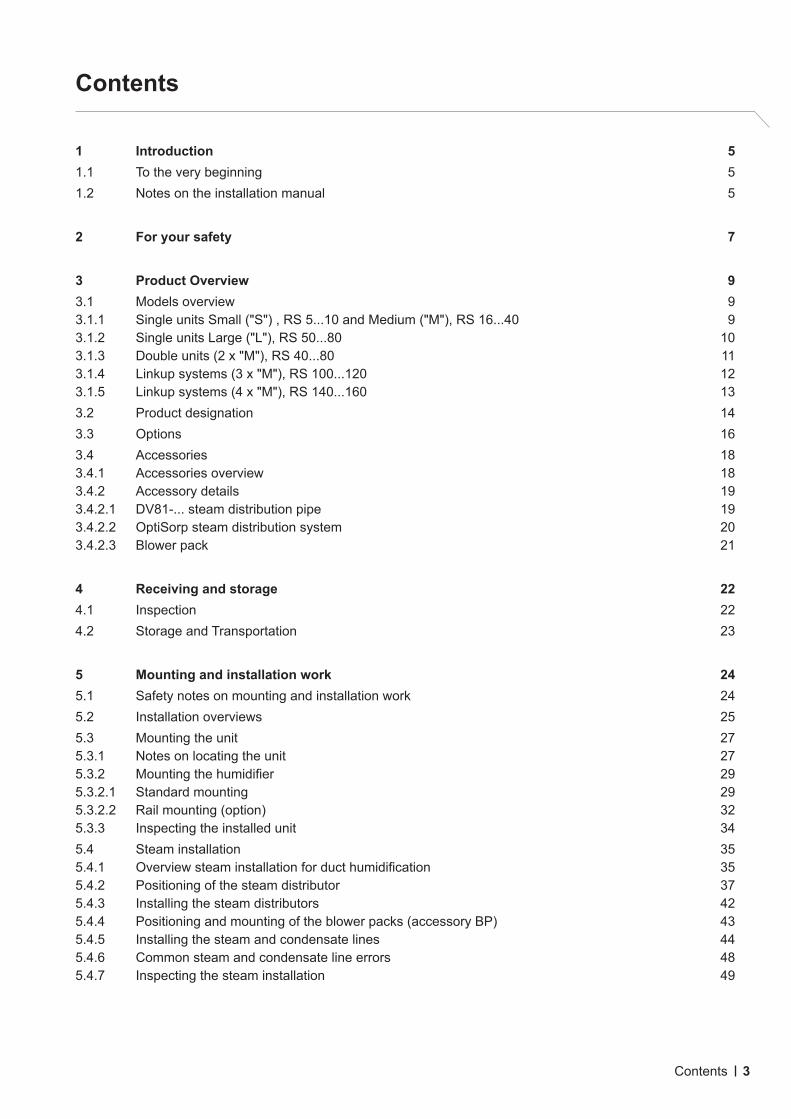
3.1.4 Linkup systems (3 x "M"), RS 100...120
Housingsize
Condair 230 V/1~ 200 V/3~ 230 V/3~ 380 V/3~ 400 V/3~ 415 V/3~ 440 V/3~ 460 V/3~ 480 V/3~ 500 V/3~ 600 V/3~
kg/h kg/h kg/h kg/h kg/h kg/h kg/h kg/h kg/h kg/h kg/h
3*MRS 100
M+E
–– –– –– ––2*30.0
+40.0
2*32.0+
43.1–– –– –– –– ––
RS 120 –– –– –– –– 3*40.0 3*43.1 –– –– –– –– ––
M= Main unit, E= Extension unit
Fig. 4: Overview Linkup systems (3 x "M")
Extension
Module A
Main
Module B
Main
Module A
50 mm
50 mm
I/OI/O
Driver boardMain A
Driver boardMain B
Control board
RFI
Heating voltage Main A
Heating voltage Main B
Control voltage
Control signal
External enable
Limiter signal
Safety chain
Remote indication
Main Module A
Main Module B
Extension Module A
Data cableSupply cable
Driver boardExtension A
Control board
Heating voltage Extension A
Control voltageExtension
Linkup cable

13Product Overview
3.1.5 Linkup systems (4 x "M"), RS 140...160
Housingsize
Condair 230 V/1~ 200 V/3~ 230 V/3~ 380 V/3~ 400 V/3~ 415 V/3~ 440 V/3~ 460 V/3~ 480 V/3~ 500 V/3~ 600 V/3~
kg/h kg/h kg/h kg/h kg/h kg/h kg/h kg/h kg/h kg/h kg/h
4*MRS 140
M+E
–– –– –– ––2*30.0
+2*40.0
2*32.0+
2*43.1–– –– –– –– ––
RS 160 –– –– –– –– 4*40.0 4*43.1 –– –– –– –– ––
M= Main unit, E= Extension unit
Fig. 5: Overview Linkup systems (4 x "M")
Extension
Module A
Extension
Module B
Main
Module B
Main
Module A
50 mm
50 mm
50 mm
I/OI/O
Driver boardMain A
Driver boardMain B
Control board
RFI
Heating voltage Main A
Heating voltage Main B
Heating voltage Extension B
Control voltage
Control signal
External enable
Limiter signal
Safety chain
Remote indication
Main Module A
Main Module B
Extension Module A
Extension Module B
Data cable Data cableSupply cable Supply cable
Driver boardExtension A
Driver boardExtension B
Control board
Heating voltage Extension A
Control voltageExtension
Linkup cable

14 Product Overview
3.2 Product designation
The identification of the unit is found on the specification label.
Fig. 6: Location of the specification label
Condair Operations GmbH, Schnackenburgallee 43-45, DE - 22525 HamburgType: Condair RS 40 P-VE Serial: XXXXXXX 05.15Voltage: 400V 3~ / 50...60Hz El. Power: 30.0 kW / 43.3 ASteam capacity: 40.0 kg/h Steam humidifierWater press.: 100..1000 kPa (1..10 bar) Main Unit, Module A
Engineered in Switzerland, Made in Germany
ProductionMonth/YearSerial number (7 digits)Type designation
Heating voltage
Maximum steam capacity
Admissible water supply pressure
Field with certification symbols
Power consumption
Device type
Module designation (shown on specification label of double units and Linkup systems only)

15Product Overview
Key model designation
Example:Condair RS 50 L 400V/3~ P VE
Product designation
Unit model:
Housing size: L: large housing
Heating voltage:230V/1~/50...60Hz: 230V/1~200V/3~/50...60Hz: 200V/3~230V/3~/50...60Hz: 230V/3~380V/3~/50...60Hz: 380V/3~400V/3~/50...60Hz: 400V/3~415V/3~/50...60Hz: 415V/3~440V/3~/50...60Hz: 440V/3~460V/3~/50...60Hz: 460V/3~480V/3~/50...60Hz: 480V/3~500V/3~/50...60Hz: 500V/3~600V/3~/50...60Hz: 600V/3~
Control accuracy:P: high control accuracy
Water management: VE: without lime collector tank for de-ionized water

16 Product Overview
3.3 OptionsVoltage Condair RS
230V/1~ 5...10 ––– ––– ––– –––
200V/3~ ––– 16...30 40...60 ––– –––
230V/3~ 5...10 16...30 40...60 ––– –––
380V/3~ 5...10 16...40 50...80 ––– –––
400...415V/3~ 5...10 16...40 50...80 100...120 140...160
440...600V/3~ 10 16/20/30/40 50...80 ––– –––
Remote operating and fault indication
PCB with relay contacts for the connec-tion of remote displays for "Operation", "Steam", "Fault" and "Service".
1xRFI 2xRFI
Accessory board
PCB with relay contacts for the connection of remote fan enable (cylinder A/B) as well as remote enable of an external hygiene flush flush valve in the water supply line (cylinder A/B).
1xACC 2xACC
Pressure compensation kit
Assembly kit for the installation of the filling cup on the equipment cover, for the opera-tion of the steam humidifier in installations with duct air pressures up to 10’000 Pa.
1xOVP 2xOVP 3xOVP 4xOVP
Transformer for internal control voltage supply (for 400...500 V mains supplies without neutral conductor) *
Kit including terminal strip and transformer to provide control voltage supply for sites with 3 phase single voltage supply without neutral conductor. Only available for supply voltages 400...500 V/3~/50...60 Hz.
1xTR-S (RS 5 ... RS 20)1xTR-M (RS 24 ... RS 40)
1xTR-S (RS 50)
or1xTR-M
(RS 60/RS80)
2xTR-M 2xTR-M
CVI for internal control voltage supply (for 400...415 V mains supplies with neutral conductor) *
Terminal strip kit to provide control volt-age supply for sites with 3 phase sin-gle voltage supply with neutral conduc-tor. Only available for supply voltages 400...415 V/3~N/50...60 Hz.
1xCVI-S (RS 5 ... RS 20)1xCVI-M (RS 24 ... RS 40)
1xCVI-S (RS 50)
or1xCVI-M
(RS 60/RS80)
2xCVI-M 2xCVI-M
Connection terminals **
Separate terminals for systems where direct connection of heating voltage to main contactor (standard version) is not permitted by local regulations
1xTHV-S (RS 5 ... RS 20)1xTHV-M (RS 24 ... RS 40)
1xTHV-S +
1xTHV-M(RS 50)
or2xTHV-M
(RS 60/RS80)
3xTHV-M 4xTHV-M
Mounting rail
Mounting rail for mounting the Condair RS to a wall or the mounting rack basic.
1xMP-S 1xMP-M 2xMP-Mor
1xMP-L for units "L"
3xMP-M 4xMP-M
LonWorks board
Supplementary board to connect the Con-dair RS to a building management system via LonWorks.
1xLW

17Product Overview
Voltage Condair RS
230V/1~ 5...10 ––– ––– ––– –––
200V/3~ ––– 16...30 40...60 ––– –––
230V/3~ 5...10 16...30 40...60 ––– –––
380V/3~ 5...10 16...40 50...80 ––– –––
400...415V/3~ 5...10 16...40 50...80 100...120 140...160
440...600V/3~ 10 16/20/30/40 50...80 ––– –––
Set of cable glands
Set with cable glands for the control com-partment of the Condair RS.
1xCG 2xCGor
1xCGfor units "L"
3xCG 4xCG
Total drain valve
Set including solenoid drain valve and hose for automatic draining of the lime collector tank.
1xSV 2xSV 3xSV 4xSV
Insulation jacket for steam cylinder 1xIC-S 1xIC-M 3xIC-M 3xIC-M 4xIC-M
Drain water cooling set
Set including special inlet valve, hose and support for drain water cooling.
1xDWC-S 1xDWC-M 2xDWC-M 3xDWC-M 4xDWC-M
* Not available for "L" units** Connection terminals (1x) included with "L" units

18 Product Overview
3.4 Accessories
3.4.1 Accessories overview
Voltage Condair RS
230V/1~ 5...10 ––– ––– ––– –––
200V/3~ ––– 16...30 40...60 ––– –––
230V/3~ 5...10 16...30 40...60 ––– –––
380V/3~ 5...10 16...40 50...80 ––– –––
400...415V/3~ 5...10 16...40 50...80 100...120 140...160
440...600V/3~ 10 16/20/30/40 50...80 ––– –––
Steam distribution pipe
Steam distribution pipe for steam dis-tribution inside a air duct (see details in chapter 3.4.2.1).
1xDV81 2xDV81 3xDV81 4xDV81
Steam distribution system OptiSorp
Steam distribution system for steam distribution inside a air duct for reduced absorption distances (see details in chapter 3.4.2.2).
OptiSorpSystem 1
OptiSorpSystem 2
OptiSorpSystem 3
OptiSorpSystem 4
Blower pack
Blower pack for direct room humidification. The blower pack can be mounted either directly onto the Condair RS or separated from the unit to the wall (see details in chapter 3.4.2.3).
1xBP 2xBP 3xBP 4xBP
Support steam for distribution pipe
Support for vertical mounting of the steam distribution pipe DV81-....
1xVS-DV81 2xVS-DV81 3xVS-DV81 4xVS-DV81
Steam hose (ø57/45 mm) / meter 1xDS80 2xDS80 3xDS80 4xDS80
Condensate hose (ø12/8 mm) / meter 1xKS10 2xKS10 3xKS10 4xKS10
Filter valve
Filter valve for the installation in the water supply line.
1xZ261 2xZ261 3xZ261 4xZ261
Mounting rack basic *
Mounting rack for Condair RS.
1xMR-B 2xMR-B 3xMR-B 4xMR-B
Height extension profiles for mounting rack basic *
Height extension profiles for mounting rack.
1xMR-E 2xMR-E 3xMR-E 4xMR-E
Screw feet for mounting rack basic *
Screw feet for levelling the mounting rack.
1xMR-A 2xMR-A 3xMR-A 4xMR-A
Humidity sensor - Room CRC
Humidity sensor - Duct CDC
Humidity controller with sensor - Room RCC
Humidity controller with sensor - Duct DCC
Humidistat - Room CHR
Humidistat - Duct CHD
* Not available for "L" units

19Product Overview
3.4.2 Accessory details
3.4.2.1 DV81-... steam distribution pipe
The steam distribution pipes are selected on the basis of the duct width "B" (for horizontal installation) or the duct height "H" (for vertical installation) and the capacity of the steam humidifier.Important! Always select the longest possible steam distribution pipe (opti mum humidification distance).
Steam distribution pipe DV81-... made of CrNi steel Duct width/duct height Max. Steam capacity Type Length in mm (L) *** in mm in kg/h
DV81-200 * 200 210...400 10
DV81-350 ** 350 400...600 30
DV81-500 ** 500 600...750 30
DV81-650 650 750...900 50
DV81-800 800 900...1100 50
DV81-1000 1000 1100...1300 50
DV81-1200 1200 1300...1600 50
DV81-1500 1500 1600...2000 50
DV81-1800 1800 2000...2400 50
DV81-2000 2000 2200...2600 50
DV81-2300 2300 2500...2900 50
DV81-2500 2500 2700...3100 50
* for units with steam capacities up to a maximum of 10 kg/h only** for units with steam capacities up to a maximum of 30 kg/h only*** Special length on request
Note: for further information regarding the DV81-... steam distribution pipe please refer to the separate installation and operating instructions of this product.
L
B
H

20 Product Overview
3.4.2.2 OptiSorp steam distribution system
The OptiSorp steam distribution system is used in ventilation ducts with a short humidification distance (for the calculation of the humidification distance refer to chapter 5.4.2). When ordering an OptiSorp system the duct dimension must be specified. Please consult the data in the following table:
System 1 System 2 System 3 System 4
Number of steam connector
1 2 3 4
Max. steam capacity 45 (30) kg/h 90 (60) kg/h 135 (90) kg/h 180 (120) kg/hDuct width (B) 450...2700mmDuct height (H) 450...1650 mm 450...2200 mm 800...3200 mm 800...3200 mm
* For duct widths <600 mm the value in brackets apply
Note: further information on the OptiSorp steam distribution system can be found in the separate manual supplied with the OptiSorp steam distribution system.
H
B
H
B
H
B
H
B

21Product Overview
3.4.2.3 Blower pack
The blower packs – in combination with the steam humidifiers Condair RS – are used for direct room humidification. The blower packs are mounted directly on the humidifier or separately above the humi-difier to the wall.
Note: further information on the blower pack can be found in the separate manual supplied with the blower pack.

22 Receiving and storage
4 Receiving and storage
4.1 Inspection
After receiving:
– Inspect shipping boxes for damage.Any damages of the shipping boxes must be reported to the shipping company without delay.
– Check packing slip to ensure all parts has been delivered.All material shortages are to be reported to your Condair supplier within 48 hours after receipt of the goods. Condair Group AG assumes no responsibility for any material shortages beyond this period.
The standard delivery includes:
– Condair RS steam humidifier equipped with the options ordered according chapter 3.3, packed in cardboard box with:– Fastening set– Installation manual (this document), operation manual and spare parts list– Water drain hose with hose clamp– Supply cable between Module A to Module B (for double units and Linkup systems only)– Data cable between Module A to Module B (for double units and Linkup systems only)– Linkup cable between "Main A" and "Externsion"A" (for Linkup systems only)Note: the supply cable, the data cable and the Linkup cable are supplied in the box of main unit A.
– Ordered accessories with manual according chapter 3.4, packed separately.
– Unpack the parts/components and check for any damage.If parts/components are damaged, notify the shipping company immediately.
– Check whether the components are suitable for installation on your site according to the unit data stated on the specification label.

23Receiving and storage
4.2 Storage and Transportation
StoringUntil installation store the Condair RS in its original packaging in a protected area meeting the following requirements:
– Room temperature: 5 ... 40 °C– Room humidity: 10 ... 75 %rh
TransportationFor optimum protection always transport the unit and components in their original packaging and use appropriate lifting/transporting devices.
WARNING!
It is the customer's responsibility to ensure that operators are trained in handling heavy goods and that the operators comply with the appropriate regulations on work safety and the prevention of accidents.
PackagingKeep the original packaging of the components for later use.
In case you wish to dispose of the packaging, observe the local regulations on waste disposal. Please recycle packaging where possible.

24 Mounting and installation work
5 Mounting and installation work
5.1 Safety notes on mounting and installation work
Qualification of personnel All mounting and installation work must be carried out only by well qualified personnel authorised by the owner. It is the owner’s responsibility to verify proper qualification of the personnel.
General notes Strictly observe and comply with all information given in the present installation manual regarding the mounting of the unit and the installation of water, steam and electricity.
Observe and comply with all local regulations dealing with water, steam and electrical installations.
SafetySome installation work requires removal of the unit covers. Please note the following:
DANGER!Danger of electric shock!
The Condair RS is mains powered. Live parts may be exposed when the unit is open. Touching live parts may cause severe injury or danger to life.Prevention: The Condair RS must be connected to the mains only after all mounting and installation work has been completed, all installations have been checked for correct workmanship and the unit is closed and properly locked.
CAUTION!
The electronic components inside the humidifier are very sensitive to electrostatic discharge.Prevention: To protect these components against damage caused by electrostatic discharge (ESD protection) appropriate measures must be taken when the unit is open for installation work.

25Mounting and installation work
5.2 Installation overviews
Typical installation for duct humidification
Fig. 7: Typical installation for duct humidification
KS10
DS80
DV81
Z261
Humidity sensor orhumidity controller
Return duct
Supply duct
Humidity sensor orhumidity controller
Steam line– As short as possible (max. length 4 m)– Adequate upslope/downslope min.15 % (8.5°)– No restrictions– Condensate trap at the lowest point – Hose or fixed pipe (with same inner diameter
as steam outlet)
Condsensate line– Min. downslope 15 % (8.5°)– No restrictions– Condensate trap ømin 200 mm
Filter valve or Shut-off valve and filter 5µm
Water drain connector ø30 mm
Water supply connector G 3/4"
Water supply pipe(min. inner diameter 8 mm, supplied by others)
1...10 bar / 1...40 °C(with optional drain water
cooling 2...10 bar / 1...25 °C)
Air proving switch(external safety chain)
Electrical isolator heating voltage supply(supplied by others)
Rmin:
300 m
m
ømin: 200 mm
ømin: 40 mm
Electrical isolator control voltage supply (supplied by others)
Drain hose (supplied)– internal diameter ø30 mm– Drain hose must be led to the left– constant downslope (min 15 %/8.5°) to funnel– if using DI or RO water, use supplied drain
hose or stainless steel pipe only– must not touch funnel
Open funnel with trap(supplied by others)
Calculated absorption distance BN to any obstruction
or min. 2.4 ... 3 m if BN is unknownmin. 3 m
High limit humidistat(external safety chain)
min.
300 m
m
min.
300 m
m
Pmax 1500 PaPmin -1000 Pa
to drainto cylinder

26 Mounting and installation work
Typical installation for room humidification
Fig. 8: Typical installation for room humidification
Z261
KS10
DS80
BP
BP Humidity sensor orhumidity controller
Steam line– As short as possible (max. length 4 m)– Adequate upslope/downslope min.15 % (8.5°)– No restrictions– Condensate trap at the lowest point – Hose or fixed pipe (with same inner diameter
as steam outlet)
Blower Pack (mounted separated from the steam humidifier)
Condsensate line– Min. downslope 15 % (8.5°)– No restrictions– Condensate trap ømin 200 mm
Filter valve or Shut-off valve and filter 5µm
Water drain connector ø30 mm
Water supply connector G 3/4"
Water supply pipe(min. inner diameter 8 mm, supplied by others)
1...10 bar / 1...40 °C(with optional drain water
cooling 2...10 bar / 1...25 °C)
Electrical isolator heating voltage supply(supplied by others)
ømin: 40 mm
Electrical isolator control voltage supply (supplied by others)
Drain hose (supplied)– internal diameter ø30 mm– Drain hose must be led to the left– constant downslope (min 15 %/8.5°) to funnel– if using DI or RO water, use supplied drain hose or stainless
steel pipe only– must not touch funnel
Open funnel with trap(supplied by others)
High limit humidistat(external safety chain)
to drain *to cylinder *
* connector used with remote
blower pack mounting only
ømin : 200 mm
27Mounting and installation work
5.3 Mounting the unit
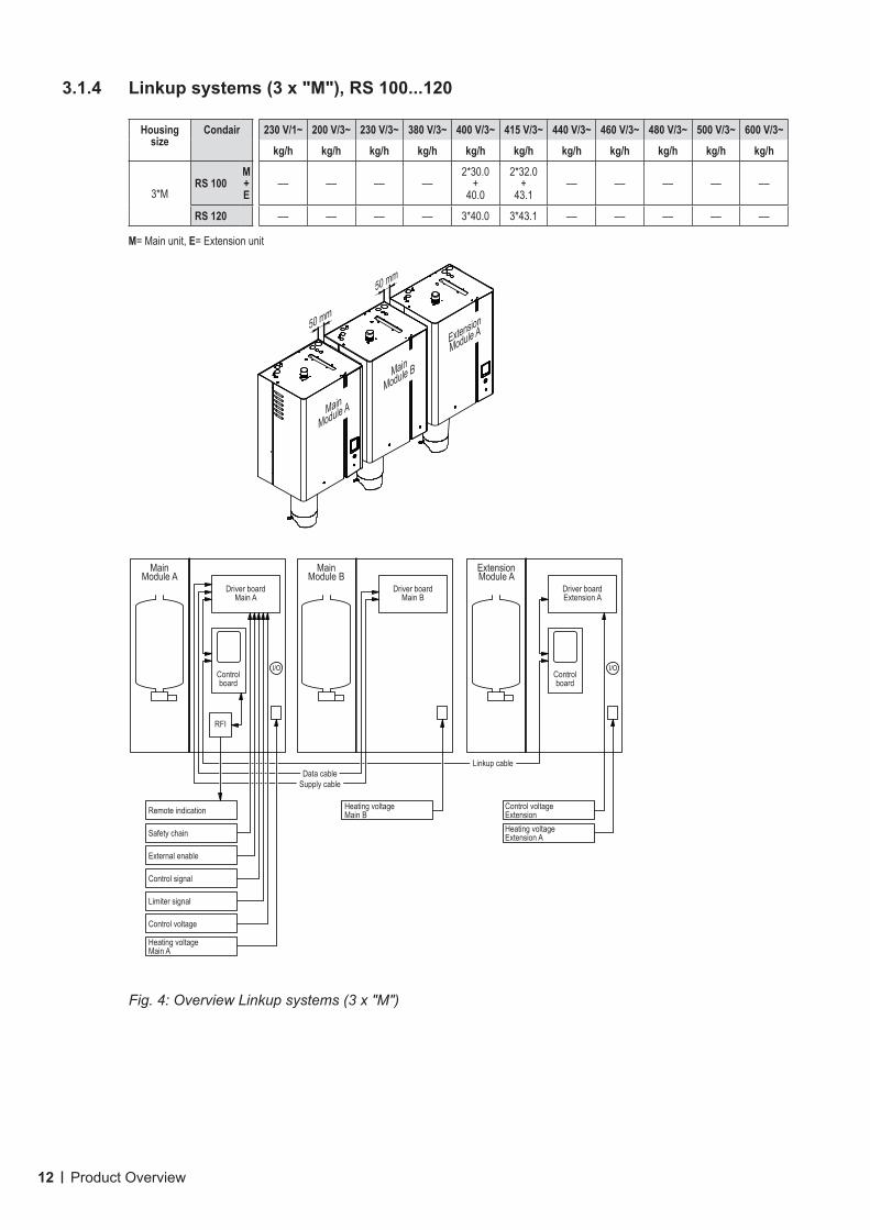
5.3.1 Notes on locating the unit
Fig. 9: Distances to be observed
Housing Small ("S")RS 5...10
Medium ("M")RS 16...40
Large ("L")RS 50...80
2x, 3x or 4x "M"for RS 40...160
Housing dimensions in mm
X 420 530 1000Y 370 406 406Z 670 780 780
Netweight in kg 27,2 40,3 81,0Operating weight in kg 40,2 65,8 132,0
Y X
Z
min. 50 mm *
min. 600 mm
min. 50 mm *
min
. 400
mm
min
. 600
mm
* recommended: 250 mm
50 mm50 mm
50 mm
Extension
Modul A
Extension
Modul B
Main
Modul B
Main
Modul A
50 mm50 mm
Extension
Modul A
Main
Modul B
Main
Modul A
50 mm
Main
Modul B
Main
Modul A
e.g. RS 602x "M"
e.g. RS 1604x "M"
e.g. RS 1203x "M"

28 Mounting and installation work
The installation site of the Condair RS depends largely on the location of the steam distributor (see chapter 5.4.2). To ensure proper functioning of the steam humidifier and to obtain an optimal efficiency, the following points must be considered and observed when choosing the location for the steam humidifier:
– Install the steam humidifier so that:
– the length of the steam line is kept as short as possible (max. 4 m),
– the minimum bend radius for steam hoses (R= 300 mm) and for solid steam pipes (5 x internal diameter) and the minimum upslope and downslope (min. 15 %/8.5°) of the steam lines is maintained (see chapter 5.4.5).
– The Condair RS is designed for wall-mounting in protected interiors. Make sure that the construction (wall, pillar, floor-mounted console, etc.) to which the humidifier is to be mounted, offers a suffi-ciently high load-bearing capacity (take notice of the weight information found in the dimensions and weights table), and is suitable for the installation.
CAUTION!
Do not mount the steam humidifier directly to the ventilation duct (insufficient stability).
– The back panel of the Condair RS retains heat during operation (max. surface temperature of the metal housing approx. 60 - 70 °C). Make sure, therefore, that the construction (wall, pillar, etc.) to which the unit is to be mounted, does not consist of heat-sensitive material.
– Install the Condair RS in such a manner that it is freely accessible with sufficient space available for maintenance purposes. The minimum distances shown in Fig. 9 must be maintained.
– In order to use the cables supplied with double units and Linkup systems, the unit must be mounted on the same height, with a maximum distance between the units of 50 mm and in the order shown in Fig. 9.
– The Condair RS is protected according to IP21. Make sure the unit is installed in a drip-proof location and the admissible ambient conditions are complied with.
– Do not mount the Condair RS to hot or very cold walls or near vibrating components.
– The steam humidifier Condair RS must only be installed in rooms with a floor drain.
CAUTION!
If for some reason the Condair RS must be installed in a location without floor drain, it is manda-tory to provide a leakage monitoring device to safely interrupt the water supply in case of leakage.
– When mounting the Condair RS use only the mounting materials supplied with the unit. If mount-ing with the materials supplied is not possible in your particular case, select a method of mounting that is of similar stability.
– The Condair RS is designed for installation and operation within buildings (admissible temperature range 5...40 °C). For outdoor operation the Condair RS must be placed in a weather protective hous-ing. If ambient temperatures near or below the freezing point have to be expected, the protective housing must equipped with a thermostat controlled heating of sufficient capacity. The water supply pipe must be equipped with a trace-heating and must be insulated up to the protective housing. The installation of a normally open valve inside the building envelope that will drain water in case of power failure is highly recommended

29Mounting and installation work
A
A
B
B
ab
c
d
Dimension Housing sizeRS 5...10 ("S") RS 16...40 ("M")
"a" in mm 54.0 54.0"b" in mm 446.0 556.0"c" in mm 80.2 88.6"d" in mm 304.8 406.4
Weights Housing sizeRS 5...10 ("S") RS 16...40 ("M")
Netweight in kg 27.2 40.3Operating weight in kg 40.2 65.8
5.3.2 Mounting the humidifier
5.3.2.1 Standard mounting
Overview standard mounting single units Small and Medium
Fig. 10: Overview standard mounting single units Small and Medium

30 Mounting and installation work
c
d
d
ab
A
A
B
B
A
B
Dimension Housing sizeRS 50...80 ("L")
"a" in mm 164.0"b" in mm 426.0"c" in mm 117.2"d" in mm 406.4
Weights Housing sizeRS 50...80 ("L")
Netweight in kg 81.0Operating weight in kg 132.0
Overview standard mounting single units Large
Fig. 11: Overview standard mounting single units Large

31Mounting and installation work
Mounting procedure standard mounting1. Mark the attachment points "A" and "B" at the desired position with the help of a level. Then, drill
holes diameter: 10 mm, depth: 50 mm.
2. Insert the supplied plastic plugs, and screw in supplied screws into the dowels of the attachment points "A" until the distance between the wall and the screw head is 5 mm.
3. Unlock the screws of the front panels of the unit, then remove the front panels.
4. Hang up the unit onto the screws installed before.
5. Screw the supplied screws through the rear wall of the housing into the dowels of of the attachment points "B".
6. Align unit with the help of a level, then tighten the screws.
7. Reattach the front panels and secure with the screws.

32 Mounting and installation work
A
B
B
B
A
a
c
b
5.3.2.2 Rail mounting (option)
Overview rail mounting single units Small and Medium
Dimension Housing sizeRS 5...10 ("S") RS 16...40 ("M")
"a" in mm 193.5 193.5"b" in mm 304.8 406.4"c" in mm 57.6 61.8
Weights Housing sizeRS 5...10 ("S") RS 16...40 ("M")
Netweight in kg 27.2 40.3Operating weight in kg 40.2 65.8
Fig. 12: Overview rail mounting single units Small and Medium

33Mounting and installation work
a
b
b
c
B
B
B
A
A
A
Dimension Housing sizeRS 50...80 ("L")
"a" in mm 263.5"b" in mm 406.4"c" in mm 117.2
Weights Housing sizeRS 50...80 ("L")
Netweight in kg 81.0Operating weight in kg 132.0
Overview rail mounting single units Large
Fig. 13: Overview rail mounting single units Large

34 Mounting and installation work
Procedure1. Mark the attachment points "A" for the mounting rail at the desired position with the help of a spirit
level. Then, drill holes diameter: 10 mm, depth: 50 mm.
2. Insert the supplied plastic plugs, and fix the mounting rail to the wall with the screws and washers supplied. Before tightening the screws adjust mounting rail horizontally using a spirit level.
3. Unlock the screw of the front panels, then remove the front panels.
4. Hang up the unit onto the mounting rail. Then, fix the unit to the mounting rail using the supplied screws "B".
5. Reattach the front panels and secure it with the screws.
5.3.3 Inspecting the installed unit
Check the following points:
Is the unit installed in the correct place (see chapter 5.3.1)?
Is the supporting surface stable enough?
Is the unit correctly aligned, vertically and horizontally?
Is the unit properly secured (see chapter 5.3.2)?
35Mounting and installation work
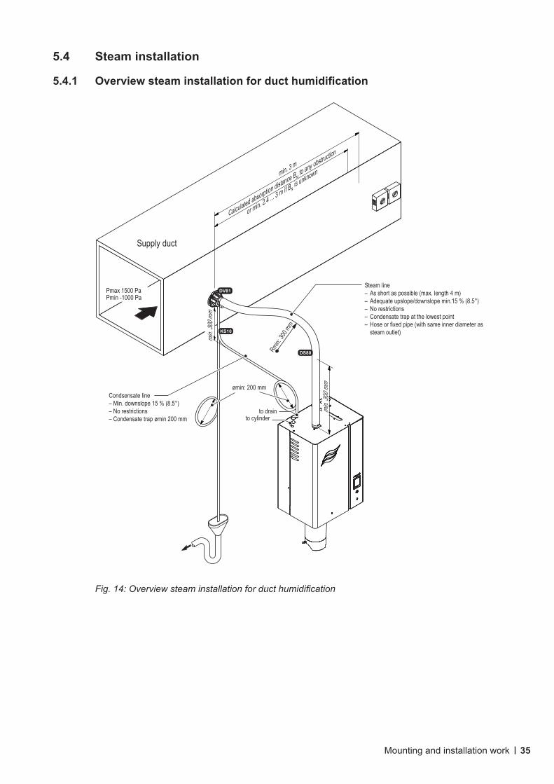
5.4 Steam installation
5.4.1 Overview steam installation for duct humidification
Fig. 14: Overview steam installation for duct humidification
KS10
DS80
DV81Steam line– As short as possible (max. length 4 m)– Adequate upslope/downslope min.15 % (8.5°)– No restrictions– Condensate trap at the lowest point – Hose or fixed pipe (with same inner diameter as
steam outlet)
Condsensate line– Min. downslope 15 % (8.5°)– No restrictions– Condensate trap ømin 200 mm
ømin: 200 mm
Calculated absorption distance BN to any obstruction
or min. 2.4 ... 3 m if BN is unknownmin. 3 m
min.
300 m
m
min.
300 m
m
Pmax 1500 PaPmin -1000 Pa
Rmin:
300 m
m
to drainto cylinder
Supply duct

36 Mounting and installation work
Steam line– As short as possible (max. length 4 m)– Adequate upslope/downslope min.15 % (8.5°)– No restrictions– Condensate trap at the lowest point – Hose or fixed pipe (with same inner diameter as
steam outlet)
Blower Pack (mounted separated from the steam humidifier)
Blower Pack (mounted directly on steam humidifier)
Condsensate line– Min. downslope 15 % (8.5°)– No restrictions– Condensate trap ømin 200 mm KS10
DS80
BP
BP
to drainto cylinder
ømin: 200 mm
Fig. 15: Overview steam for room humidification

37Mounting and installation work
5.4.2 Positioning of the steam distributor
The location of the steam distributor should be determined at the time of dimensioning the air condition-ing system. Please note the following instructions to ensure proper humidification of the duct air.
Calculating the absorption distanceThe steam, emitting from the steam distributor, requires a certain distance to be absorbed by the air so that it is no longer visible as steam. This distance is referred to as absorption distance "BN" and serves as a basis for the determination of the minimum distances from the upstream components in the system
Fig. 16: Absorption distance "BN"
The calculation of the absorption distance "BN" is dependent on several factors. For a rough estimation of the absorption distance "BN", the following table is useful. Recommended standard values listed in this table are based on a supply-air temperature range of 15 °C to 30 °C. The values given in bold type apply to steam distribution pipes DV81-..., the values in brackets apply to the OptiSorp steam distribution system.
Humidity at inletϕ1 in %rh
Length of absorption distance BN in mHumidity at outlet ϕ2 in %rh
40 50 60 70 80 905 0,9 (0,22) 1,1 (0,28) 1,4 (0,36) 1,8 (0,48) 2,3 (0,66) 3,5 (1,08)10 0,8 (0,20) 1,0 (0,26) 1,3 (0,34) 1,7 (0,45) 2,2 (0,64) 3,4 (1,04)20 0,7 (0,16) 0,9 (0,22) 1,2 (0,30) 1,5 (0,41) 2,1 (0,58) 3,2 (0,96)30 0,5 (0,10) 0,8 (0,17) 1,0 (0,25) 1,4 (0,36) 1,9 (0,52) 2,9 (0,88)40 – 0,5 (0,11) 0,8 (0,20) 1,2 (0,30) 1,7 (0,45) 2,7 (0,79)50 – – 0,5 (0,13) 1,0 (0,24) 1,5 (0,38) 2,4 (0,69)60 – – – 0,7 (0,16) 1,2 (0,30) 2,1 (0,58)70 – – – – 0,8 (0,20) 1,7 (0,45)
φ1 in %rh: Relative supply air humidity prior to humidification at the lowest supply air temperatureφ2 in %rh: Relative supply air humidity after the steam distribution pipe at maximum capacityFor duct widths <600 mm the absorption distance for the OptiSorp system increases by approx. 50%
φ1: Supply air humidity before humidificationφ2: Supply air humidity after humidification
Expansion and mixing zoneAbsorption distance BN
Safety humidistat / Humidity sensor

38 Mounting and installation work
Examplegiven φ1= 30 %rh, φ2= 70 %rhabsorption distance BN: 1,4 m
(0.36 m for steam distribution system OptiSorp)
Note: If the absorption distance has to be reduced for technical reasons, the amount of steam per unit must be divided between several steam distribution pipes or the steam distribution system OptiSorp must be used. If this is the case, contact your Condair representative.
Minimum distances to be observedTo prevent the steam, that is emitting from the steam distributor, from condensing on downstream system components, a minimum distance to the steam distributor must be observed (depends on the absorp-tion distance "BN").
before/after constriction after expansion
0.5 x BN
(1.97")
50 mm
0.5 x BN
before bend before branch
1 x BN1 x BN

39Mounting and installation work
before diffuser before humidity controller/ humidity sensor
1 x BN 5 x BN
before/after filter/heater
+
1.5 x BN *
(1.97")
50 mm
2,5 x BN before aerosol filter
before/after fan, zone exit
(1.97")
50 mm
1 x BN
1 x BN

40 Mounting and installation work
Installation notesThe steam distribution pipes are designed for either horizontal installation (on the duct wall) or, with ac-cessories, for vertical installation (in the duct floor). The outlet orifices should always point upwards and at right angles to the airflow.
If possible, the steam distribution pipes should be installed on the pressure side of the duct (max. duct pressure 1500 Pa). If the steam distribution pipes are installed on the suction side of the duct, the maximum vacuum must not exceed 1000 Pa.
Select a location for the installation, tailored to suit your duct (see the following illustrations) and position the steam distribution pipes in the duct so that a uniform distribution of steam is achieved.
Positioning the steam distribution pipes in the ductIn positioning the steam distribution pipes, the following dimensions should be observed:
H
1/3
2/3
hmin
H min.= 250 mmh min.= 85 mm
H
1/21/2
H ≥400 mm
H
1/2
1/2
H min.= 200 mm
H min.= 400 mm
H
2/7
2/7
3/7
H min.= 350 mmg min.= 150 mm
H
2/7
2/7
3/7
gmin
H min.= 300 mm
H 1/3
1/3
1/3

41Mounting and installation work
H
1/5
1/5
1/5
2/5
H min.= 600 mm
H
1/5
1/5
1/5
2/5
gmingmin
H min.= 500 mmg min.= 150 mm
H 1/4
1/4
1/4
1/4
H min.= 400 mm
H min.= 720 mm
H
1/6
1/6
1/6
1/6
2/6
H min.= 600 mmg min.= 150 mm
H
1/6
1/6
1/6
1/6
2/6gmin
gmingmin
H min.= 500 mm
H1/5
1/5
1/5
1/5
1/5
Note: When locating the OptiSorp steam distribution system please note the instructions in the separate documentation for this product.

42 Mounting and installation work
Guidelines for dimensioning the ventilation ducts– To facilitate the installation of the steam distribution pipes and for control purposes, a sufficiently
sized control opening should be planned.
– Within the range of the absorption distance, the ventilation duct should be waterproofed.
– Air ducts passing through cold rooms should be insulated to prevent the humidified air from condens-ing along the duct wall.
– Poor airflow conditions within the air duct (e.g. caused by obstacles, tight bends, etc.) can lead to condensation of the humidified air.
– Steam distribution pipes must not be mounted to round ducts.
If you have questions relating to the dimensioning of ventilation ducts in combination with steam humidi-fiers Condair RS, contact your Condair representative.
5.4.3 Installing the steam distributors
Detailed information on the installation of steam distribution pipes DV81-... and OptiSorp steam distribu-tion system can be found in the separate mounting instructions for these products.

43Mounting and installation work
5.4.4 Positioning and mounting of the blower packs (accessory BP)
The blower packs can either be mounted directly on the humidifier or separately above the humidifier to the wall. To allow the steam coming from the blower pack to spread out evenly, without condensing on obstacles (ceilings, joists, pillars, etc.), the following minimum dimensions must be observed when selecting the location for the blower pack.
Fan speed: low Fan speed: highSteam capacity humidifier kg/h 5...10 >10...20 >20...30 >30...40 5...10 >10...20 >20...30 >30...40A min. m 2.5 5.5 8.0 9.5 2.0 3.0 4.5 6.5B min. m 0.5 0.5 0.5 1.5 0.5 0.5 0.5 1.0C min. m 2.2D min. m 0.5E min. m 1.0E max. m 4.0 (recommended: 2.0)
Note: The minimum spaces in the table apply for a room atmosphere of 15 °C and 60 %rh. For lower temperatures and/or higher humidity the values should be adjusted accordingly.
Note: In order to achieve a uniform distribution of the humidity within the room, additional factors such as the room size, the room height, etc., must be taken into consideration besides observing the minimum distances for the blower packs. If you have questions concerning the direct room humidification, please contact your Condair representative.
Further information is provided in the separate installation and operating instructions for the correspond-ing blower pack.
A
C
B
D
D
C
B
E
D
D
A
44 Mounting and installation work
5.4.5 Installing the steam and condensate lines
Installations notes– Use original steam and condensate hose from your Condair representative or solid steam pipes
from copper or stainless steel (min. DIN 1.4301) exclusively. Steam and condensate lines from other material may cause undesired operational malfunctions.
– Initially, lead the steam line upright upwards min. 300 mm above the humidifier. Then lead the steam line with a minimum upslope and/or a minimum downslope of 15 %/8.5° to the steam distributor.
– The condensate hose from the steam distributor is led down to the humidifier with a minimum downslope of 15 %/8.5°, via a condensate trap (min. hose bend diameter Ø200 mm) and there it is to be connected to the appropriate connector on top of the unit.Important! Before putting the unit into operation, the condensate trap of the condensate hose must be filled with water.
– The steam line should be kept as short as possible (max. 4 m while observing the minimum bend radius of 300 mm (for steam hoses) or 5 x internal diameter (with solid steam pipes), respectively.Important! Allowance must be made for a pressure loss of approx. 100 Pa per meter steam line and per 90° elbow.
– Important! When deciding on the length and layout of steam hoses, it should be noted that steam hoses may become shorter and/or longer depending on temperature and age.
– The steam hose must be secured to the steam distributor and humidi fier steam outlet by means of hose clamps. Solid steam pipes should be connected to the steam distributor and steam humidifier with short lengths of steam hose secured with hose clamps.Caution! Do not overtighten the hose clamp on the steam connector of the steam humidifier.
– Steam lines made of solid pipes (copper or stainless steel) must be insulated over the entire length to minimize condensate formation (=loss).
DANGER!
Reducing the cross section or the complete closure of the steam line will cause an exces-sive increase in pressure in the steam cylinder when the unit is operating and could lead to the risk of scalding accidents. All installations must comply with the following instructions.
– When installing make sure the steam line is open over the entire length and through the whole cross section. Any sealing plugs, adhesive sealing sheets etc. must be removed before connecting the steam pipe. Reductions in cross section by kinking or crushing must be avoided.
– Steam hoses must be prevented from sagging (condensate pockets); if necessary, support steam hose with pipe clamps, trough, or wall brackets, and install a condensate drain at any low points in the steam line.
– It is not permitted to install a stop valve (e.g. a manually controlled stop valve, solenoid valve, etc.) in the steam line, due to an inadmissible increase of pressure in the steam cylinder if the valve is closed during the operation.Note: If for technical reasons a stop valve is to be installed, the pressure relief valve (available as accessory) must be installed in the steam line between steam cylinder and and stop valve for safety reason.

45Mounting and installation work
Installation examples
Fig. 17: Steam distributor mounted more than 500 mm above the top edge of the humidifier
Ømin. 200 mm
Ømin. 200 mm
Rmin. 300 mm
Rmin. 300 mmmin.
300 m
m
min.
300 m
m
max.
4 m
max.
4 m
min.
300 m
m
min.
300 m
m
Accessory: VS-DV81

46 Mounting and installation work
Fig. 18: Steam distributor mounted less than 500 mm above the top edge of the humidifier
Obstacle
Install condensate drain (full size T) at the lowest point
Ømin.
200 mm
Rmin. 300 mm
min.
300 m
m
max.
4 m min.
300 m
m
Ømin.
200 mm
Ømin.
200 mm
Rmin. 300 mmRm
in. 30
0 mm
max.
4 m
min.
300 m
m
min.
300 m
m
min.
300 m
m
Ensure adequate cooling according to local codes
Ensure adequate cooling according to local codes

47Mounting and installation work
Fig. 19: Steam line with solid piping and insulation
Steam line must be insulated over the entire length!
max. 4 m
Ømin. 200 mm
Rmin. 5 x D
min.
300 m
m
min.
300 m
m

48 Mounting and installation work
5.4.6 Common steam and condensate line errors
Wrong Correct1 Steam line not led at least 11.81" (300 mm) perpendicularly
upwards before first bend (forming of condensate).Lead steam line at least 11.81" (300 mm) perpendicularly upwards before first bend.
2 Minimum bend radius of steam hose/solid steam line not maintained (forming of condensate).
The minimum bend radius of 11.81" (300 mm) for steam hoses or 5 times steam line internal diameter for solid steam lines must be maintained.
3 Condensate trap not sufficiently high and installed too near at the steam distributor.
The condensate trap must be at least 300 mm below the con-nector on the steam distributor and it must have a minimum height of 200 mm (ø200 mm).
4 No condensate trap installed at vertical transition. Install condensate trap at all low points and before vertical transitions.
5 Steam line and condensate hose not sloped (slope min. 20 %). Install steam line always with constant up or downslope of min.15 % (8.5°) and condensate hose with constant downslope of min.15 % (8.5°).
Fig. 20: Common steam and condensate line errors
1
2
3
4
5

49Mounting and installation work
5.4.7 Inspecting the steam installation
Use the following check list to ensure that the steam installation was performed correctly:
– Steam distributor
Steam distributors (steam distribution pipe or OptiSorp steam distribution system) correctly positioned and secured (screws tightened)?
Are the outlet orifices at right angles to the air flow for horizontal installation, or at 45 degree angle for vertical installation?
– Steam hose
Maximum length of 4 m?
Minimum bend radius of 300 mm (5 x internal diameter with fixed piping)?
Have the instructions for hose layout been followed?
Steam hose: no sagging (condensate pocket) or condensate drain with trap (hose bend with a minimum diameter of 200 mm) installed at the lowest point?
Fixed steam lines: properly insulated? Correct installation material used? Minimum internal diameter maintained?
Steam hose or steam hose pieces securely attached with clamps?
Heat expansion during operation and shortening of the hose with ageing taken into considera-tion?
– Condensate hose
Downslope of at least 20 %?
Trap (min. ø200 mm) in place and filled with water?
Condensate hose correctly connected and supported and not kinked?

50 Mounting and installation work
5.5 Water installation
5.5.1 Overview water installation
Fig. 21: Overview water installation for single units Small ("S") and Medium ("M")
Fig. 22: Overview water installation for single units Large ("L")
Filter valve or Shut-off valve and filter 5µm
Water drain connector ø30 mm
Water supply connector G 3/4"
Water supply pipe(min. inner diameter 8 mm, supplied by others) Drain hose (supplied)
– internal diameter ø30 mm– Drain hose must be led to the left– constant downslope (min 15 %/8.5°) to funnel– must not touch funnel– if using DI or RO water, use supplied drain hose or stainless
steel pipe only
Open funnel with trap(supplied by others)
ømin: 40 mm
1...10 bar / 1...40 °C(with optional drain water
cooling 2...10 bar / 1...25 °C)
Filter valves or Shut-off valves and filters 5µm
Water drain connectors ø30 mm
Water supply connectors G 3/4"
Water supply pipes(min. inner diameter 8 mm,
supplied by others)
Drain hoses (supplied)– internal diameter ø30 mm– Drain hoses must be led to the left– constant downslope (min 15 %/8.5°) to funnel– must not touch funnel– if using DI or RO water, use supplied drain hoses or stainless
steel pipes only
Open funnels with trap(supplied by others)
ømin: 40 mm
1...10 bar / 1...40 °C(with optional drain water
cooling 2...10 bar / 1...25 °C)
51Mounting and installation work
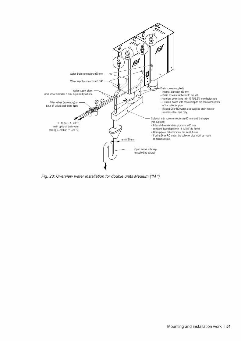
Fig. 23: Overview water installation for double units Medium ("M ")
Filter valves (accessory) or Shut-off valves and filters 5µm
Water drain connectors ø30 mm
Water supply connectors G 3/4"
Water supply pipes(min. inner diameter 8 mm, supplied by others)
Drain hoses (supplied)– internal diameter ø30 mm– Drain hoses must be led to the left– constant downslope (min 15 %/8.5°) to collector pipe– Fix drain hoses with hose clamp to the hose connectors
of the collector pipe– if using DI or RO water, use supplied drain hose or
stainless steel pipe only
Collector with hose connectors (ø30 mm) and drain pipe (not supplied)– Internal diameter drain pipe min. ø60 mm– constant downslope (min 15 %/8.5°) to funnel– Drain pipe of collector must not touch funnel– if using DI or RO water, the collector pipe must be made
of stainless steel
Open funnel with trap(supplied by others)
1...10 bar / 1...40 °C(with optional drain water
cooling 2...10 bar / 1...25 °C)
ømin: 60 mm

52 Mounting and installation work
5.5.2 Notes on water installation
Water supplyThe water supply is to be carried out according to the figure found in chapter 5.5.1 and the applicable local regulations for water installations. The indicated connection specifications must be observed.
– The installation of the filter valve (accessory "Z261", alternatively a shut-off valve and a 5 µm water filter can be used) should be made as close as possible to the steam humidifier.Note: on large units with two steam cylinders, on double units and on Linkup systems each unit must be connected separately via a filter valve (or shut-off valve and water filter) to the water supply.
– Admissible water supply pressure:– 1.0…10.0 bar (units without drain water cooling)– 2.0…10.0 bar (units with drain water cooling)
Note: the supply water system must be hammer-free. For mains pressures >10 bar, the connection must be made via a pressure reducing valve (adjusted to 2.0 bar). For mains pressures <1.0 bar (units without drain water cooling) <2.0 bar (units with drain water cooling) please contact your Condair supplier.
– Notes on water quality:
– For the water supply of the Condair RS, use exclusively untreated drinking water, water from RO system or de-ionized water.
– The use of additives such as corrosion inhibitors, disinfectants, etc. is not allowed, since these additives may endanger health and affect proper operation.
– The connection material must be pressure-proof and certified for use in drinking water systems.
– Important! Before connecting the water line, the line must be well flushed out.
CAUTION!
The thread at the humidifier connection is made of plastic. To avoid overtightening, the union nut of the water pipe must be tightened by hand only.
Water drainThe water drain is to be carried out according to the figures found in chapter 5.5.1 and the applicable local regulations for water installations. The indicated connection specifications must be observed.
– Make sure that the drain pipes, the funnel(s) and the siphon(s) are correctly fixed and easily acces-sible for inspections and cleaning purposes.
– The draining temperature is: 80…90 °C (with optional drain water cooling <60°C). Use temperature-resistant installation materials only!
– Always lead the supplied drain hose from the connector to the left down to the funnel (see Fig. 21).
On large units with two steam cylinders each drain line must be led into a separate funnel with trap (see Fig. 22).
On double unit the drain hoses must be connected with hose clamps to a collector with constant downslope (min. 15 %/8.5°). The drain of the collector must be led with constant downslope (min. 15 %/8.5°) into a funnel with trap (see Fig. 23). The funnel must be positioned with a lateral off-set to the left side of the unit, to prevent damage to humidifier due to rising steam.
– Attach drain line(s) in such a way, that it/they cannot slip out of the funnel(s) and that it/they cannot bottom out in the funnel(s).
– The open end of the drain line(s) must not touch the funnel(s) (min. air gap 2 cm).

53Mounting and installation work
5.5.3 Inspecting the water installation
Check the following topics:
– Water supply
Has filter valve (accessory "Z261") or shut-off valve and 5 µm water filter respectively been installed in supply line to each unit module?
Has acceptable water pressure (without drain water cooling: 1 – 10 bar, with drain water cooling: 2 – 10 bar) and acceptable water temperature (without drain water cooling: 1 – 40 °C, with drain water cooling: 1 – 25 °C) been connected?
Does the water supply capacity match the humidifier and is the minimum inside diameter of 8 mm of the supply pipe maintained throughout the entire length (min. internal diameter of 12 mm for systems with optional drain water cooling recomended)?
Are all components and pipes properly secured and are all threaded connections securely tight-ened?
Is the water system properly sealed?
Does the water supply installation meet the requirements of the local regulations for water instal-lations?
– Water drain
Is the minimum inside diameter of the drain pipe(s) of 30 mm maintained throughout the entire length?
Has/have drain pipe(s) been installed with a downslope of at least 15 %/8.5°?
Has the heat resistance of the material used been verified to be at least 100 °C (60 °C for sys-tems with optional drain water cooling)?
Is/are the drain hose(s) properly secured (hose clamps at unit connection tightened)?
Is there an air gap (min 2 cm) between the open end of the drain line and the funnel?
Does the water drain installation meet the requirements of the local regulations for water instal-lations?

54 Mounting and installation work
5.6 Notes on humidity control systems/humidity control
5.6.1 System 1 – Room humidity controlSystem 1 is suited for direct room humidification and air conditioning systems with mainly recir-culated air. The humidity sensor or humidistat respectively is preferably located in the room itself or in the exhaust air duct.
Fig. 24: System 1 – Room humidity control
5.6.2 System 2 – Room humidity control with continuous limitation of the supply air humiditySystem 2 is suited for air conditioning systems with a large portion of supply air, low supply air temperature, post-humidification, or variable airflow volume. If the supply air hum idity exceeds the preset value, the continuous limitation is effected prior to the room hum idity control.The humidity sensor (A1) is preferably located in the exhaust air duct or in the room itself. The humidity sensor (A2) for the limitation of the supply air humidity is located in the supply air duct after the steam distribution pipe. This control system requires a continuous controller with the option to connect a second humidity sensor.Attention! The continuous limitation of the supply air humidity is no substitute for the safety humi distat.
A1/2 humidity sensorB1 ventilation interlockB2 airflow monitorB3 safety humidistatPII Internal P/PI controllerPIE External continuous controller (e.g. PI controller)Y input signal from A1Z input signal from A2
A1 humidity sensorB1 ventilation interlockB2 airflow monitorB3 safety humidistatB4 humidistatPII Internal P/PI controllerPIE External continuous controller (e.g. PI controller)Y input signal from A1
Fig. 25: System 2 – Room humidity control with continuous limitation of the supply air humidity

55Mounting and installation work
5.6.3 System 3 – Supply air humidity control with continuous output limit ation
Supply air humidity control (humidity sensor installed in supply air duct) should be used only where room humidity control is impracticable for technical reasons. Such systems always require a PI-controller.The humidity sensor (A1) is located in the supply air duct after the steam distribution pipe. The humidity sensor (A2) for the continuous output limitation is located in the supply air duct before the steam distri-bution pipe. Such a system requires a PI-controller with the option to connect a second humidity sensor.
Fig. 26: System 3 – Supply air humidity control with continuous output limit ation
5.6.4 Which humidity control system for which application
Application Location of the humidity sensorroom or exhaust air duct supply air duct
Air conditioning systems with:– supply air portion up to 33% System 1 System 1– supply air portion up to 66% System 1 or 2 System 2 or 3– supply air portion up to 100% System 2 System 3– supply air humidity control — System 3Direct room humidification System 1 —
Please contact your Condair supplier, if your application meets the following conditions:– Humidification of small rooms up to 200 m3
– Air conditioning systems with a high number of air exchanges– Systems with variable air volume flow– Test facilities with extreme control accuracy requirements– Rooms with a high variation in max. steam capacity– Systems with temperature fluctuations– Cold rooms and systems with dehumidification
A1/2 humidity sensorB1 ventilation interlockB2 airflow monitorB3 safety humidistatPII Internal PI controllerPIE External PI controllerY input signal from A1Z input signal from A2

56 Mounting and installation work
5.6.5 Admissible control signals
Control with external controller Control with internal PI controllerControl signals Humidity sensor signals
0...5 VDC 0...5 VDC1...5 VDC 1...5 VDC
0...10 VDC (Potentiometer 140 Ω ... 10 kΩ) 0...10 VDC (Potentiometer 140 Ω ... 10 kΩ)2...10 VDC 2...10 VDC0...20 VDC 0...20 VDC0...16 VDC 0...16 VDC
3.2...16 VDC 3.2...16 VDC0 ... 20 mA 0 ... 20 mA4 ... 20 mA 4 ... 20 mA
Humidistat (24 V On/Off)

57Mounting and installation work
5.7 Electrical installation
5.7.1 Notes on electrical installation
DANGER!Danger of electric shock
The Condair RS is mains powered. Live parts may be exposed when the unit is open. Touching live parts may cause severe injury or danger to life.Prevention: The Condair RS unit must be connected to the mains only after all mounting and instal-lation work has been completed, all installations have been checked for correct workmanship and the unit is closed and properly locked.
CAUTION!
The electronic components inside the unit are very sensitive to electrostatic discharge. Before carrying out installations work inside the unit, appropriate measures must be taken to protect the electronic components against damage caused by electrostatic discharge (ESD protection).
– All work concerning the electrical installation must be performed only by skilled and qualified technical personnel (e.g. electrician with appropriate training) authorised by the owner. It is the owner’s responsibility to verify proper qualification of the personnel.
– The electrical installation must be carried out according to the corresponding wiring diagram (see chapters 5.7.2 / 5.7.3 / 5.7.4 / 5.7.5), the notes on electrical installation as well as the applicable local regulations. All information given in the wiring diagrams and notes must be followed and observed.
– All cables must be lead into the unit, via appropriate cable strain relief or grommets. The cable for the heating voltage supply must be lead into the unit from the bottom via the cable opening equipped with the clamp. Fix the cable with the clamp strap.
– Make sure the cables are adequately clamped, do not rub on any components or become a tripping hazard.
– Observe and maintain maximum cable length and required cross section per wire according to local regulations.
– The mains supply voltages (heating and control voltage supply) must match the respective voltage stated on the specification label.

58 Mounting and installation work
ACCE
SSOR
Y BO
ARD
REMO
TE B
OARD
BMS
LinkU
pSA
B3V
CR2032BAT
SD
J7J4
J8
J11
(USB)
(RJ45)
GND
+–
GND
+–
GND
+–
24VG
NDMAINS SUPPLYL N SC1SC2PEPE
MODULE B24VDC
LEVELUNIT
POWERBOARD
DRN1 J2 INLET J1 PWRSUPPLY
BLOWERLIMIT ENABLECONTROLV+
X8 X9 X12
X11
X10
X7 X1
INGND IN GND 24V IN24V IN 24V GND
RS485RS485
PWRIC
CONT-ACTOR
HEAT GR.2+3
JP2 (24V)JP1 (10V)
PUMPAC
SWITCH
GNDD–
D+GND
D–D+
24VGND
DRN2 J3
F1
SW1
F2
H1
Error
1 2 3
Service
4 5 6
Steam
7 8
Unit On
9 10
H2
Hyg. Valve A FAN B
1 2 3
Hyg. Valve B
4 5 6 7 8
FAN A
9 10
L1 L2 L3
L1 L2 L3 PE
K1
THV
Q3
F3
Y1
200-600 V/3~/50..60 Hz
230 V/1~/50..60 HzL1 N PE
Q3
F3
B3
B2
B1
L1 N PE
F4
Q4
230 V/1~/50..60 Hz
K2J3
J1
230V
M
L1 N PE
140Ω...10kΩA2
On/OffA3
GND
INV+INV+
JP1
JP2
A1 A4Y+ –
Z+ –
B4
140Ω...10kΩA5
GND
INV+
JP1
Z
L1 L2 L3
400-500 V/3~/50..60 Hz
400-415 V/3~N/50..60 Hz
F3
Q3
L2 L3L1
L2 L3 PEL1
L1 N PE
F3
Q3
L2 L3 PENL1
L2 L3L1N PEL1
Control compartment
Driver board
Option TR (3Ph)
Option CVI (3Ph+N)
5.7.2 Wiring diagram Condair RS 5...40 - Single units "S" and "M"
Fig. 27: Wiring diagram Condair RS - Single units "S" and "M" (5...40 kg/h)
A1 Continuous humidity controller (active) or humidity sensorA2 Ohmic humidity controller (passive),
set jumper JP1 and remove jumper JP2A3 On/Off humidity controller,
set jumper JP2 and remove jumper JP1A4 Limiter signalA2 Ohmic limiter controller, set jumper JP1 and remove jumper JP2B1 Ventilation interlockB2 Airflow monitorB3 Safety humidistatB4 External enable contactF1 Internal fuse 24V supply (1 A, slow acting)F2 Internal fuse 230V supply (6.3 A, slow acting)F3 External fuse heating voltage supply
(see table in chapter 5.7.7)F4 External fuse control voltage (max. 10 A, slow acting)J1 Jumper wire, if blower pack safety loop is not connectedJ3 Jumper wire, if no monitoring devices are connected to SC1 and SC2J4 Jumper for activating the terminating resistor for Modbus network
(Jumper must be connected, if Condair RS is the last unit in the Modbus network)
J7 Jumper for activating Modbus or BACnet MSTP communication via RS485 interface (J6). If jumper is not in place no communication will take place through the RS485 interface.
H1 Remote operating and fault indication (option)H2 Accessory board (option) for the control of an external fan of the AHU
as well as the optional external valve for the water supply line flushingK1 Mains contactor (heating voltage)K2 External safety circuit (safety humidistat, airflow monitor, etc.)M Motor blower packQ3 External main switch heating voltage supplyQ4 External main switch control voltage supplySW1 Rotary switch Module identification (must be left on position "0")THV Terminal Heating voltage supply (option)Y1 Total drain valve (option)
6.3 A, slow acting
6.3 A, slow acting
Ethe
rnet
(RJ4
5)IP
netw
ork /
BMS
BAC
net IP
RS 48
5BA
Cnet
MSTP
Control board

59Mounting and installation work
5.7.3 Wiring diagram Condair RS 50...80 - Single units "L"
Fig. 28: Wiring diagram Condair RS - Single units "L" 50...80 kg/h
H1
Error
1 2 3
Service
4 5 6
Steam
7 8
Unit On
9 10
H2
Hyg. Valve A FAN B
1 2 3
Hyg. Valve B
4 5 6 7 8
FAN A
9 10
MAINS SUPPLYL N SC1SC2PEPE
MODULE B24VDC
LEVELUNIT
POWERBOARD
DRN1 J2 INLET J1 PWRSUPPLY
BLOWERLIMIT ENABLECONTROLV+
X8 X9 X12
X11
X10
X7 X1
INGND IN GND 24V IN24V IN 24V GND
RS485RS485
PWRIC
CONT-ACTOR
HEAT GR.2+3
JP2 (24V)JP1 (10V)
PUMPAC
SWITCH
GNDD–
D+GND
D–D+
24VGND
DRN2 J3
F1
SW1
F2
MAINS SUPPLYL N SC1SC2PEPE
MODULE B24VDC
LEVELUNIT
POWERBOARD
DRN1 J2 INLET J1 PWRSUPPLY
BLOWERLIMIT ENABLECONTROLV+
X8 X9 X12
X11
X10
X7 X1
INGND IN GND 24V IN24V IN 24V GND
RS485RS485
PWRIC
CONT-ACTOR
HEAT GR.2+3
JP2 (24V)JP1 (10V)
PUMPAC
SWITCH
GNDD–
D+GND
D–D+
24VGND
DRN2 J3
F1
SW1
F2
ACCE
SSOR
Y BO
ARD
REMO
TE B
OARD
BMS
LinkU
pSA
B
3V
CR2032BAT
SD
J7J4
J8
J11
(USB)
(RJ45)
GND
+–
GND
+–
GND
+–
24VG
ND
L1 L2 L3
L1 L2 L3
K1
L1 L2 L3
L1 L2 L3 PE
Q3
F3
400-415 V/3~/50..60 Hz
B3
K2
B2
B1
L1 N PE
F4
Q4
230 V/1~/50..60 Hz
J3
230V
140Ω...10kΩA2
On/OffA3
GND
INV+INV+
JP1
JP2
A1 A4Y+ –
Z+ –
B4
140Ω...10kΩA5
GND
INV+
JP1Z
Y1Y1
J1
J1 J3
Control compartment
Module A Module B
Control board
Driver board Module B
Driver board Module A
A1 Continuous humidity controller (active) or humidity sensorA2 Ohmic humidity controller (passive), set jumper JP1 and remove jumper JP2A3 On/Off humidity controller, set jumper JP2 and remove jumper JP1A4 Limiter signalA2 Ohmic limiter controller, set jumper JP1 and remove jumper JP2B1 Ventilation interlockB2 Airflow monitorB3 Safety humidistatB4 External enable contactF1 Internal fuse 24V supply (1 A, slow acting)F2 Internal fuse 230V supply (6.3 A, slow acting)F3 External fuse heating voltage supply (see table in chapter 5.7.7)F4 External fuse control voltage (max. 10 A, slow acting)J1 Jumper wire, if blower pack safety loop is not connectedJ3 Jumper wire, if no monitoring devices are connected to SC1 and SC2J4 Jumper for activating the terminating resistor for Modbus network (Jumper must be connected, if Condair RS
is the last unit in the Modbus network)J7 Jumper for activating Modbus or BACnet MSTP communication via RS485 interface (J6). If jumper is not in
place no communication will take place through the RS485 interface.H1 Remote operating and fault indication (option)H2 Accessory board (option) for the control of an external fan of the AHU as well as the optional external valve for
the water supply line flushingK1 Mains contactor (heating voltage) module A / module BK2 External safety circuit (safety humidistat, airflow monitor, etc.)Q3 External main switch heating voltage supplyQ4 External main switch control voltage supplySW1 Rotary switch Module identification (Module A: 0, Module B: 1)Y1 Total drain valve (option)
Ethe
rnet
(RJ4
5)IP
netw
ork /
BMS
BAC
net IP
RS 48
5BA
Cnet
MSTP

60 Mounting and installation work
H1
Error
1 2 3
Service
4 5 6
Steam
7 8
Unit On
9 10
H2
Hyg. Valve A FAN B
1 2 3
Hyg. Valve B
4 5 6 7 8
FAN A
9 10
DRN2 J3
F1
SW1
F2
MAINS SUPPLYL N SC1SC2PEPE
MODULE B24VDC
LEVELUNIT
POWERBOARD
DRN1 J2 INLET J1 PWRSUPPLY
BLOWERLIMIT ENABLECONTROLV+
X8 X9 X12
X11
X10
X7 X1
INGND IN GND 24V IN24V IN 24V GND
RS485RS485
PWRIC
CONT-ACTOR
HEAT GR.2+3
JP2 (24V)JP1 (10V)
PUMPAC
SWITCH
GNDD–
D+GND
D–D+
24VGND
MAINS SUPPLYL N SC1SC2PEPE
MODULE B24VDC
LEVELUNIT
POWERBOARD
DRN1 J2 INLET J1 PWRSUPPLY
BLOWERLIMIT ENABLECONTROLV+
X8 X9 X12
X11
X10
X7 X1
INGND IN GND 24V IN24V IN 24V GND
RS485RS485
PWRIC
CONT-ACTOR
HEAT GR.2+3
JP2 (24V)JP1 (10V)
PUMPAC
SWITCH
GNDD–
D+GND
D–D+
24VGND
DRN2 J3
F1
SW1
F2
ACCE
SSOR
Y BO
ARD
REMO
TE B
OARD
BMS
LinkU
pSA
B
3V
CR2032BAT
SD
J7J4
J8
J11
(USB)
(RJ45)
GND
+–
GND
+–
GND
+–
24VG
ND
L1 L2 L3 PE
Q3
F3
200-600 V/3~/50..60 Hz
230 V/1~/50..60 HzL1 N PE
Q3
F3
L1 L2 L3 PE
Q3
F3
200-600 V/3~/50..60 Hz
230 V/1~/50..60 HzL1 N PE
Q3
F3
B3
K2
B2
B1
L1 N PE
F4
Q4
230 V/1~/50..60 Hz
J3
230V
140Ω...10kΩA2
On/OffA3
GND
INV+INV+
JP1
JP2
A1 A4Y+ –
Z+ –
B4
12
140Ω...10kΩA5
GND
INV+
JP1Z
L1 L2 L3
K1
THV
L1 L2 L3
L1 L2 L3
K1
THV
L1 L2 L3Y1
Y1J1 J3
J1
400-415 V/3~N/50..60 Hz 400-415 V/3~/50..60 Hz
400-500 V/3~/50..60 Hz 400-500 V/3~/50..60 Hz
F3
Q3
L2 L3L1
L2 L3 PEL1
L1 N PE
F3
Q3
L2 L3 PENL1
L2 L3L1 L2 L3L1N PEL1
F3
Q3
PE
L2 L3 PEL1
L2 L3L1
F3
Q3
PE
L2 L3 PEL1
Ethe
rnet
(RJ4
5)IP
netw
ork /
BMS
BAC
net IP
RS 48
5BA
Cnet
MSTP
Control compartment Module A Control compartment Module B
Control board
Driver board Module B
Driver board Module A
A1 Continuous humidity controller (active) or humidity sensorA2 Ohmic humidity controller (passive), set jumper JP1 and remove
jumper JP2A3 On/Off humidity controller, set jumper JP2 and remove jumper JP1A4 Limiter signalA2 Ohmic limiter controller, set jumper JP1 and remove jumper JP2B1 Ventilation interlockB2 Airflow monitorB3 Safety humidistatB4 External enable contactF1 Internal fuse 24V supply (1 A, slow acting)F2 Internal fuse 230V supply (6.3 A, slow acting)F3 External fuse heating voltage supply
(see table in chapter 5.7.7)F4 External fuse control voltage (max. 10 A, slow acting)J1 Jumper wire, if blower pack safety loop is not connectedJ3 Jumper wire, if no monitoring devices are connected to
SC1 and SC2J4 Jumper for activating the terminating resistor for Modbus network
(Jumper must be connected, if Condair RS is the last unit in the Modbus network)
J7 Jumper for activating Modbus or BACnet MSTP communication via RS485 interface (J6). If jumper is not in place no communication will take place through the RS485 interface.
H1 Remote operating and fault indication (option)H2 Accessory board (option) for the control of an external fan of the AHU
as well as the optional external valve for the water supply line flushingK1 Mains contactor (heating voltage) module A / module BK2 External safety circuit (safety humidistat, airflow monitor, etc.)Q3 External main switch heating voltage supplyQ4 External main switch control voltage supplySW1 Rotary switch Module identification (Module A: 0, Module B: 1)THV Terminal Heating voltage supply (option)Y1 Total drain valve (option)
1 Supply cable Module A to Module B - 1,65 m (supplied)2 Data cable Module A to Module B - 1,65 m (supplied)
Option TR (3Ph)
6.3 A, slow acting
6.3 A, slow acting
Option CVI (3Ph+N)
5.7.4 Wiring diagram Condair RS 40...80 - Double units 2 x "M"
Fig. 29: Wiring diagram Condair RS - Double units (2 x "M") 40...80 kg/h

61Mounting and installation work
5.7.5 Wiring diagram RS 100...160 - Linkup systems 3 x "M" or 4 x "M"
Fig. 30: Wiring diagram RS - Linkup systems 100...160 kg/h
H1
Error
1 2 3
Service
4 5 6
Steam
7 8
Unit On
9 10
H2
Hyg. Valve A FAN B
1 2 3
Hyg. Valve B
4 5 6 7 8
FAN A
9 10
MAINS SUPPLYL N SC1SC2PEPE
MODULE B24VDC
LEVELUNIT
POWERBOARD
DRN1 J2 INLET J1 PWRSUPPLY
BLOWERLIMIT ENABLECONTROLV+
X8 X9 X12
X11
X10
X7 X1
INGND IN GND 24V IN24V IN 24V GND
RS485RS485
PWRIC
CONT-ACTOR
HEAT GR.2+3
JP2 (24V)JP1 (10V)
PUMPAC
SWITCH
GNDD–
D+GND
D–D+
24VGND
F1
SW1
F2
DRN2 J3
MAINS SUPPLYL N SC1SC2PEPE
MODULE B24VDC
LEVELUNIT
POWERBOARD
DRN1 J2 INLET J1 PWRSUPPLY
BLOWERLIMIT ENABLECONTROLV+
X8 X9 X12
X11
X10
X7 X1
INGND IN GND 24V IN24V IN 24V GND
RS485RS485
PWRIC
CONT-ACTOR
HEAT GR.2+3
JP2 (24V)JP1 (10V)
PUMPAC
SWITCH
GNDD–
D+GND
D–D+
24VGND
F1
SW1
F2
DRN2 J3
ACCE
SSOR
Y BO
ARD
REMO
TE B
OARD
BMS
LinkU
pSA
B3V
CR2032BAT
SD
J7J4
J8
J11
(USB)
(RJ45)
GND
+–
GND
+–
GND
+–
24VG
ND
L1 L2 L3 PE
Q3
F3
400-415 V/3~/50..60 HzL1 L2 L3 PE
Q3
F3
400-415 V/3~/50..60 Hz
B3
K2
B2
B1 L1 N PE
F4
Q4
230 V/1~/50..60 Hz
J3230V
MAINS SUPPLYL N SC1SC2PEPE
MODULE B24VDC
LEVELUNIT
POWERBOARD
DRN1 J2 INLET J1 PWRSUPPLY
BLOWERLIMIT ENABLECONTROLV+
X8 X9 X12
X11
X10
X7 X1
INGND IN GND 24V IN24V IN 24V GND
RS485RS485
PWRIC
CONT-ACTOR
HEAT GR.2+3
JP2 (24V)JP1 (10V)
PUMPAC
SWITCH
GNDD–
D+GND
D–D+
24VGND
DRN2 J3
F1
SW1
F2
MAINS SUPPLYL N SC1SC2PEPE
MODULE B24VDC
LEVELUNIT
POWERBOARD
DRN1 J2 INLET J1 PWRSUPPLY
BLOWERLIMIT ENABLECONTROLV+
X8 X9 X12
X11
X10
X7 X1
INGND IN GND 24V IN24V IN 24V GND
RS485RS485
PWRIC
CONT-ACTOR
HEAT GR.2+3
JP2 (24V)JP1 (10V)
PUMPAC
SWITCH
GNDD–
D+GND
D–D+
24VGND
DRN2 J3
F1
SW1
F2
ACCE
SSOR
Y BO
ARD
REMO
TE B
OARD
BMS
LinkU
pSA
B
3V
CR2032BAT
SD
J7J4
J8
J11
(USB)
(RJ45)
GND
+–
GND
+–
GND
+–
24VG
ND
L1 L2 L3 PE
Q3
F3
400-415 V/3~/50..60 HzL1 L2 L3 PE
Q3
F3
400-415 V/3~/50..60 HzL1 N PE
F4
Q4
230 V/1~/50..60 Hz
2 1
2 1
3
140Ω...10kΩA2
On/OffA3
GND
INV+INV+
JP1
JP2
A1 A4Y+ –
Z+ –
B4
140Ω...10kΩA5
GND
INV+
JP1Z
L1 L2 L3
K1
THV
L1 L2 L3
L1 L2 L3
K1
THV
L1 L2 L3
L1 L2 L3
K1
THV
L1 L2 L3
L1 L2 L3
K1
THV
L1 L2 L3
Y1
Y1
Y1
Y1
J1 J3
J1
J1 J3
J1 J3H1
Error
1 2 3
Service
4 5 6
Steam
7 8
Unit On
9 10
H2
Hyg. Valve A FAN B
1 2 3
Hyg. Valve B
4 5 6 7 8
FAN A
9 10
Control compartment "Main A"
Control compartment "Extension A"
Control compartment "Main B"
Control compartment "Extension B"
Ethe
rnet
(RJ4
5)IP
netw
ork /
BMS
BAC
net IP
RS 48
5BA
Cnet
MSTP
Option TR (3Ph)
Option TR (3Ph)
Option CVI (3Ph+N)
Option CVI (3Ph+N)
Control board"Extension"
Control board"Main"
Driver board "Extension B"
Driver board "Main B"
Driver board "Extension A"
Driver board "Main A"

62 Mounting and installation work
Legend
A1 Continuous humidity controller (active) or humidity sensorA2 Ohmic humidity controller (passive), set jumper JP1 and remove jumper JP2A3 On/Off humidity controller, set jumper JP2 and remove jumper JP1A4 Limiter signalA2 Ohmic limiter controller, set jumper JP1 and remove jumper JP2B1 Ventilation interlockB2 Airflow monitorB3 Safety humidistatB4 External enable contactF1 Internal fuse 24V supply (1 A, slow acting)F2 Internal fuse 230V supply (6.3 A, slow acting)F3 External fuse heating voltage supply (see table in chapter 5.7.7)F4 External fuse control voltage (max. 10 A, slow acting)J1 Jumper wire, if blower pack safety loop is not connectedJ3 Jumper wire, if no monitoring devices are connected to SC1 and SC2J4 Jumper for activating the terminating resistor for Modbus network (Jumper must be connected, if Condair RS is the last
unit in the Modbus network)J7 Jumper for activating Modbus or BACnet MSTP communication via RS485 interface (J6). If jumper is not in place no
communication will take place through the RS485 interface.J8 Termination Linkup system (Jumper must be connected, if the Condair RS is the first or the last unit in the Linkup system).H1 Remote operating and fault indication (option)H2 Accessory board (option) for the control of an external fan of the AHU as well as the optional external valve for the
water supply line flushingK1 Mains contactor (heating voltage) Main A / Main B and Extension A / Extension BK2 External safety circuit (safety humidistat, airflow monitor, etc.)Q3 External main switch heating voltage supplyQ4 External main switch control voltage supplySW1 Rotary switch Module identification (Module A: 0, Module B: 1)THV Terminal Heating voltage supply (option)Y1 Total drain valve (option)
1 Supply cable Module A to Module B - 1,65 m (supplied)2 Data cable Module A to Module B - 1,65 m (supplied)3 Linkup cable - 2,5 m (supplied)

63Mounting and installation work
5.7.6 Installation work external connections
Connecting the external safety chain
B3
B2
B1
MAINS SUPPLYL N SC1SC2PEPE
J3
K2Control compartment
Do not apply extraneous voltage via K2!
DANGER: 230 V
The potential-free contacts of external moni t or ing de-vices (e.g. ventilation interlock "B1", airflow monitor "B2", safety high limit humidistat "B3", etc.) are connected in series (safety chain "K2") to the terminals "SC1" and "SC2" of the terminal block "X1" on the driver board in accordance with the wiring diagram. The connecting cable must be led through a cable gland into the control compartment.
Caution! A high limit humidistat is highly recomen-ded to prevent risk of over-humidification and potential damage to property.
Note: If, for whatever reason, no external monitoring de-vices are connected, a jumper wire "J3" must be installed on the contacts "SC1" and "SC2" of the terminal block.
CAUTION! Do not apply any extraneous voltage to contacts "SC1" and "SC2" via the contacts of the external monitoring devices.
Humidity control wiringConnecting a demand or humidity signal
CONTROLV+ IN GND
JP2 (24V)JP1 (10V)
+ –A1
Y
24V
/10
V
Control compartment
The signal cable of an external controller or of a humid-ity sensor (if the internal P/PI controller is used) are to be connected according to the wiring diagram to the terminals "IN" and GND" on the driver board in the control compartment. The connecting cable must be led through a cable gland into the control compartment.
Note: if the external controller or the humidity sensor shall be supplied with 10 V or 24 V from the driver board (terminal “A+”), the jumper JP1 must be set to 10V or 24V accordingly.
Note: the humidity control must be configured via the control software accordingly. The admissible humidity control signal values can be found in the technical data table in the operation manual.
If a shielded signal cable is used, connect the shielding to terminal "GND". Caution! If the shielding of the control signal is already connected to a po ten tial or a grounded conductor, do not connect it to terminal "GND"

64 Mounting and installation work
Connecting an ohmic humidity controller (passive)
140Ω...10kΩA2
CONTROLV+ IN GND
JP2 (24V)JP1 (10V)
Control compartment
The signal cable of an ohmic humidity controller (140Ω...10kΩ) is to be connected according to the wir-ing diagram to the terminals "V+", "IN" and GND" on the driver board in the control compartment. The connecting cable must be led through a cable gland into the control compartment.
Note: when connecting an ohmic humidity controller Jumper "JP2" must be removed and Jumper "JP1" must be connected on the driver board and the control signal type must be set to 0-10V in the control settings of the control software.
Connecting a 24V On/Off humidistat
On/OffA3
CONTROLV+ IN GND
JP2 (24V)JP1 (10V)
Control compartment
The signal cable of 24V On/Off humidistat is to be connected according to the wiring diagram to the ter-minals "V+" and "IN" on the driver board in the control compartment.The connecting cable must be led through a cable gland into the control compartment.
Note: when connecting a 24V On/Off humidistat Jumper "JP1" must be removed and Jumper "JP2" connected.
Limiter wiringConnecting an external limiter controller or a humidity sensor
A4
LIMITIN GND
+ –Z
Control compartment
The signal cable of an external limiter (P/PI continuous controller) or of a humidity sensor (if the internal P/PI limiter controller is used) is to be connected according to the wiring diagram to the terminals "IN" (+) and "GND" (–) on the driver board in the control compartment.The connecting cable must be led through a cable gland into the control compartment.
Note: the limiter must be activated and configured via the control software accordingly. The admissible limiter signal values can be found in the technical data table in the operation manual.

65Mounting and installation work
Connecting an external ohmic limiter controller
LIMITIN GND
140Ω...10kΩA5
CONTROLV+ IN GND
JP2 (24V)JP1 (10V)
Control compartment
The signal cable of an ohmic limiter controller (140Ω...10kΩ) is to be connected according to the wir-ing diagram to the terminals "V+" (CONTROL terminal) and "IN" and GND" (LIMIT terminal) on the driver board in the control compartment. The connecting cable must be led through a cable gland into the control compartment.
Note: when connecting an ohmic limiter controller Jumper "JP2" must be removed and Jumper "JP1" must be connected on the driver board. The limiter must be activated and limiter signal type must be set to 0-10V in the control settings of the control software.
Connecting the optional remote operating and fault indication
Error Service Steam Unit On
F1 (100 mA)
H1
1 2 3 4 5 6 7 8 9 10
Control compartment
The optional remote operating and fault indication board contains four potential-free relay contacts for the con-nection of the following operating and fault indications:– "Error" (Terminal 1 and 2):
This relay is activated if an error is present.– "Service" (Terminal 4 and 5):
This relay is activated when the set maintenance interval has elapsed.Note: this relay can be configured in the control software to close either when maintenance is re-quired or when maintenance is required and when a warning is indicated.
– "Steam" (Terminal 7 and 8): This relay closes as soon as the Condair EL hu-midifies.
– "Unit on" (Terminal 9 and 10): This relay closes as soon as the voltage supply to the Control compartment of the Condair EL is switched on.
The connecting cable must be led through a cable gland or grommet into the control compartment.
The maximum contact loading is 250V/8A.
Appropriate suppressor modules are to be used for the switching of relays and miniature contactors.

66 Mounting and installation work
Connecting the optional accessory board
F1 (100 mA)
H2
Hyg. Valve A FAN B
1 2 3
Hyg. Valve B
4 5 6 7 8
FAN A
9 10
Control compartment
The optional accessory board contains four potential-free relay contacts to activate external fans of the AHU and the optional valves for flushing the water supply lines:– "Hyg. Valve A" (Terminal 1 and 2):
This relay activates the optional valve for flushing the water supply line connected to module A.
– "Hyg. Valve B" (Terminal 4 and 5): This relay activates the optional valve for flushing the water supply line connected to module B.
– "FAN B" (Terminal 7 and 8): This relay activates an external fan of the AHU if module B is producing steam.
– "FAN A" (Terminal 9 and 10): This relay activates an external fan of the AHU if module A is producing steam.
The connecting cable must be led through a cable gland or grommet into the control compartment.
The maximum contact loading is 250V/8A.
Connecting the total drain valve (option)
DRN1 J2 INLET J1DRN2 J3
Y1
Control compartment
The connecting cable of the optional total drain valve "Y1" is to be connected according to the wiring diagram to the terminal block "DRN2 J3" on the (appropriate) driver board in the control compartment.
The connecting cable must be led through a cable gland into the control compartment.
Note: if the total drain valve is retrofitted, it must be activated via the control software. In this case contact your Condair representative.

67Mounting and installation work
Connecting the control voltageNote: if the Condair RS is equipped with option "CVI" or "TR", a separate control voltage supply is not required.
MAINS SUPPLYL N SC1SC2 PEPE
L1 N PE
F4
Q4
230 V/1~/50..60 Hz
Control compartment
The control voltage supply (L1, N, PE) is to be con-nected in accordance with the wiring diagram to the corresponding terminals on the driver board in the control compartment.
The installation of the fuse" F4" (10A, slow acting) and the electrical isolator "Q4" (all pole disconnecting device with a minimum contact clearance of 3 mm, sup-plied by others) in the mains supply line are mandatory.
The electrical isolator must be mounted in direct prox-imity of the control compartment (max. distance 1 m) and must be easily accessible in a height between 0.6 m and 1.9 m (recommended: 1.7 m) .
CAUTION! Make sure the voltage indicated on the specification label meets the local mains voltage. Oth-erwise, do not connect the unit.
The cross-section of the cable must comply with the applicable local regulations (minimum of 1.5 mm2).

68 Mounting and installation work
Connecting the heating voltage supply
L1 L2 L3
L1 L2 L3 PE
K1
Q3
F3
200-600 V/3~/50..60 Hz
230 V/1~/50..60 HzL1 N PE
Q3
F3
L1 L2 L3
L1 L2 L3 PE
K1
Q3
F3
200-600 V/3~/50..60 Hz
230 V/1~/50..60 HzL1 N PE
Q3
F3
L1THV L2 L3L1THV L2 L3
Control compartment(Module A)
Control compartment(Module B)
The heating voltage supply (L1, L2, L3 and PE or L1, N and PE) is to be connected in accordance with the wiring diagram to the corresponding terminals of the main contactor "K1" (or to the corresponding terminals of the optional terminal strip "THV") in the control compartment. The supply wiring is to be fed into the unit via the cable guide with clamp on the bottom of the unit.
Notes:– Double units consisting of two housings have separate heating voltage supplies for each module
(cylinder).– Large units with two cylinders have a single heating voltage supply which is branched to each of
the two modules.
The installation of the fuses "F3" and the electrical isolator "Q3" (all pole disconnecting device with a minimum contact clearance of 3 mm, supplied by others) in the mains supply line are mandatory.
Note: a table with the values for the fuses "F3" is to be found in chapter 5.7.7.
The electrical isolator must be mounted in direct proximity of the control compartment (max. distance 1 m) and must be easily accessible in a height between 0.6 m and 1.9 m (recommended: 1.7 m) .
CAUTION! Make sure the voltage indicated on the specification label meets the local mains voltage. Otherwise, do not connect the unit.
The cross-section of the mains cable must comply with the applicable local regulations.

69Mounting and installation work
Connecting the heating voltage supply via option TR (for 3 phase single voltage system)
MAINS SUPPLYL N SC1SC2PEPE
MODULE BX7 X1
MAINS SL N SC1
MODULE B
X7 X1
L1 L2 L3
K1
L2 L3L1
PE
L1 N PE
F3
Q3
L2 L3 PEL1
L1 L2 L3
F3
Q3
L2 L3L1
K1
L1THV L2 L3
400-500 V/3~/50..60 Hz 400-500 V/3~/50..60 Hz
6.3 A, slow acting
Option TR
Control compartment (Module B)
Control compartment(Module A)
Supply cable(Module A / Module B)
The voltage supply (L1, L2, L3 and PE) is to be connected in accordance with the wiring diagram to the corresponding terminals of the option TR. The supply wiring is to be fed into the unit via the clamp strap on the bottom of the unit.Note: On double units consisting of two housings the heating voltage supply for module B is connected directly to the corresponding terminals of the main contactor "K1" or to the corresponding terminals of the optional terminal strip "THV". The control voltage supply to module B is established via the supply cable connected to the terminal strips "X7" on the driver boards of module A and module B.
The installation of the fuses "F3" and the electrical isolator "Q3" (all pole disconnecting device with a minimum contact clearance of 3 mm, supplied by others) in the mains supply line are mandatory.
Note: a table with the values for the fuses "F3" is to be found in chapter 5.7.7.
The electrical isolator must be mounted in direct proximity of the control compartment (max. distance 1 m) and must be easily accessible in a height between 0.6 m and 1.9 m (recommended: 1.7 m).
CAUTION! Make sure the voltage indicated on the specification label meets the local mains voltage. Otherwise, do not connect the unit.
The cross-section of the mains cable must comply with the applicable local regulations.

70 Mounting and installation work
Connecting the voltage supply via Option CVI (for 3 phase/neutral single voltage system)
F3
Q3
L2 L3 PENL1
L2 L3L1N PEL1
MAINS SUPPLYL N SC1SC2PEPE
MODULE B
X7 X1
MAINS SL N SC1
MODULE B
X7 X1
L1 L2 L3
K1
F3
Q3
L2 L3 PEL1
L1 L2 L3
K1
L1THV L2 L3
400-415 V/3~N/50..60 Hz 400-415 V/3~/50..60 Hz
6.3 A, slow acting
Option CVI
Control compartment (Module B)
Control compartment(Module A)
Supply cable(Module A / Module B)
The voltage supply (L1, L2, L3, N and PE) is to be connected in accordance with the wiring diagram to the corresponding terminals of the option CVI. The supply wiring is to be fed into the unit via the clamp strap on the bottom of the unit.Note: On double units consisting of two housings the heating voltage supply for module B is connected directly to the corresponding terminals of the main contactor "K1" or to the corresponding terminals of the optional terminal strip "THV". The control voltage supply to module B is established via the supply cable connected to the terminal strips "X7" on the driver boards of module A and module B.
The installation of the fuses "F3" and the electrical isolator "Q3" (all pole disconnecting device with a minimum contact clearance of 3 mm, supplied by others) in the mains supply line are mandatory.
Note: a table with the values for the fuses "F3" is to be found in chapter 5.7.7.
The electrical isolator must be mounted in direct proximity of the control compartment (max. distance 1 m) and must be easily accessible in a height between 0.6 m and 1.9 m (recommended: 1.7 m).
CAUTION! Make sure the voltage indicated on the specification label meets the local mains voltage. Otherwise, do not connect the unit.
The cross-section of the mains cable must comply with the applicable local regulations.
Connecting the blower pack BPSee separate documentation for blower pack BP.

71Mounting and installation work
5.7.7 Performance data / Fuses "F3" Heating voltage supply
230V/1~/50...60 Hz 200V/3~/50...60 Hz 230V/3~/50...60 Hz 380V/3~/50...60 Hz 400V/3~/50...60 Hz 415V/3~/50...60 Hz
Max.
steam
capa
city
in kg
/hP N m
ax.
in kW
I N max
. in
ACa
ble cr
oss s
ectio
nA L m
in. in
mm2
Fuse
s "F3
" in
A, qu
ick ac
ting (
gR)
Max.
steam
capa
city
in kg
/hP N m
ax.
in kW
I N max
. in
ACa
ble cr
oss s
ectio
nA L m
in. in
mm2
Fuse
s "F3
" in
A, qu
ick ac
ting (
gR)
Max.
steam
capa
city
in kg
/hP N m
ax.
in kW
I N max
. in
ACa
ble cr
oss s
ectio
nA L m
in. in
mm2
Fuse
s "F3
" in
A, qu
ick ac
ting (
gR)
Max.
steam
capa
city
in kg
/hP N m
ax.
in kW
I N max
. in
ACa
ble cr
oss s
ectio
nA L m
in. in
mm2
Fuse
s "F3
" in
A, qu
ick ac
ting (
gR)
Max.
steam
capa
city
in kg
/hP N m
ax.
in kW
I N max
. in
ACa
ble cr
oss s
ectio
nA L m
in. in
mm2
Fuse
s "F3
" in
A, qu
ick ac
ting (
gR)
Max.
steam
capa
city
in kg
/hP N m
ax.
in kW
I N max
. in
ACa
ble cr
oss s
ectio
nA L m
in. in
mm2
Fuse
s "F3
" in
A, qu
ick ac
ting (
gR)
S
RS 5 8.0 4.0 16.5 4.0 20 –– –– –– –– –– 5.0 3.8 9.4 1.5 16 4.6 3.4 5.2 1.5 10 5.0 3.8 5.5 1.5 10 5.4 4.1 6.0 1.5 10
RS 8 8.0 6.5 26.0 6.0 32 –– –– –– –– –– 8.0 6.0 15.0 2.5 20 7.3 5.4 8.3 1.5 10 8.0 6.0 8.7 1.5 10 8.7 6.5 9.0 1.5 10
RS 10 9.8 8.0 32.0 10.0 40 –– –– –– –– –– 9.8 7.4 18.5 6.0 32 9.0 6.7 10.2 1.5 16 10.0 7.5 11.0 1.5 16 10.7 8.0 11.5 1.5 16
M
RS 16 –– –– –– –– –– 14.9 11.2 32.2 10.0 40 16.0 12.0 30.1 10.0 40 14.5 10.9 16.6 2.5 20 16.0 12.0 17.4 2.5 20 17.3 13.0 18.1 2.5 20
RS 20 –– –– –– –– –– 18.1 13.6 39.2 16.0 63 19.7 14.8 37.1 16.0 63 17.9 13.4 20.4 6.0 25 20.0 14.9 21.5 6.0 25 21.4 16.0 22.3 4.0 25
RS 24 –– –– –– –– –– 22.3 16.7 48.3 16.0 63 24.0 18.0 45.1 16.0 63 21.8 16.3 24.8 6.0 32 24.0 18.1 26.2 6.0 32 26.0 19.5 27.2 6.0 32
RS 30 –– –– –– –– –– 30.0 22.5 65.0 25.0 80 29.5 22.1 55.6 25.0 80 26.9 20.1 30.6 10.0 40 30.0 22.3 32.3 10.0 40 32.0 24.0 33.5 10.0 40
RS 40 –– –– –– –– –– –– –– –– –– –– –– –– –– –– –– 36.1 27.1 41.1 16.0 63 40.0 30.0 43.3 16.0 63 43.1 32.3 45.0 16.0 63
2*M
RS 40 –– –– –– –– –– 2*18.1 2*13.6 2*39.2 2*16.0 2*63 2*19.7 2*14.8 2*37.1 2*16.0 2*63 –– –– –– –– –– –– –– –– –– –– –– –– –– –– ––
RS 50A+B
–– –– –– –– ––18.1
+ 30.0
13.6+
22.5
39.2+
65.0
16.0+
25.0
63+80
19.7+
29.5
14.8+
22.1
37.1+
55.6
16.0+
25.0
63+80
17.9+
26.9
13.4+
20.1
20.4+
30.6
6.0+
10.0
25+40
20.0+
30.0
14.9+
22.3
21.5+
32.3
6.0+
10.0
25+40
21.4+
32.0
16.0+
24.0
22.3+
33.5
4.0+
10.0
25+40
L RS 50 –– –– –– –– –– –– –– –– –– –– –– –– –– –– –– –– –– –– –– –– 50.0 37.2 53.7 25.0 80 53.4 40.0 57.7 16.0 63
2*M RS 60 –– –– –– –– –– 2*30.0 2*30.0 2*65.0 2*25.0 2*80 2*29.5 2*22.1 2*55.6 2*25.0 2*80 2*26.9 2*20.1 2*30.6 2*10.0 2*40 2*30.0 2*22.3 2*32.3 2*10.0 2*40 2*32.0 2*24.0 2*33.5 2*10.0 2*40
L RS 60 –– –– –– –– –– –– –– –– –– –– –– –– –– –– –– –– –– –– –– –– 60.0 44.6 64.4 25.0 80 64.0 48.0 69.3 25.0 80
2*M RS 80 –– –– –– –– –– –– –– –– –– –– –– –– –– –– –– 2*36.1 2*27.1 2*41.1 2*16.0 2*63 2*40.0 2*30.0 2*43.3 2*16.0 2*63 2*43.1 2*32.3 2*45.0 2*16.0 2*63
L RS 80 –– –– –– –– –– –– –– –– –– –– –– –– –– –– –– –– –– –– –– –– 80.0 60.0 86.6 35.0 125 86.2 64.6 93.2 35.0 125
3*MRS 100
M+E
–– –– –– –– –– –– –– –– –– –– –– –– –– –– –– –– –– –– –– ––2*30.0
+40.0
2*22.3+
30.0
2*32.3+
43.3
2*10.0+
16.0
2*40+63
2*32.0+
43.1
2*24.0+
32.3
2*33.5+
45.0
2*10.0+
16.0
2*40+63
RS 120 –– –– –– –– –– –– –– –– –– –– –– –– –– –– –– –– –– –– –– –– 3*40.0 3*30.0 3*43.3 3*16.0 3*63 3*43.1 3*32.3 3*45.0 3*16.0 3*63
4*MRS 140
M+E
–– –– –– –– –– –– –– –– –– –– –– –– –– –– –– –– –– –– –– ––2*30.0
+2*40.0
2*22.3+
2*30.0
2*32.3+
2*43.3
2*10.0+
2*16.0
2*40+
2*63
2*32.0+
2*43.1
2*24.0+
2*32.3
2*33.5+
2*45.0
2*10.0+
2*16.0
2*40+
2*63
RS 160 –– –– –– –– –– –– –– –– –– –– –– –– –– –– –– –– –– –– –– –– 4*40.0 4*30.0 4*43.3 4*16.0 4*63 4*43.1 4*32.3 4*45.0 4*16.0 4*63
440V/3~/50...60 Hz 460V/3~/50...60 Hz 480V/3~/50...60 Hz 500V/3~/50...60 Hz 600V/3~/50...60 Hz
Max.
steam
capa
city
in kg
/hP N m
ax.
in kW
I N max
. in
ACa
ble cr
oss s
ectio
nA L m
in. in
mm2
Fuse
s "F3
" in
A, qu
ick ac
ting (
gR)
Max.
steam
capa
city
in kg
/hP N m
ax.
in kW
I N max
. in
ACa
ble cr
oss s
ectio
nA L m
in. in
mm2
Fuse
s "F3
" in
A, qu
ick ac
ting (
gR)
Max.
steam
capa
city
in kg
/hP N m
ax.
in kW
I N max
. in
ACa
ble cr
oss s
ectio
nA L m
in. in
mm2
Fuse
s "F3
" in
A, qu
ick ac
ting (
gR)
Max.
steam
capa
city
in kg
/hP N m
ax.
in kW
I N max
. in
ACa
ble cr
oss s
ectio
nA L m
in. in
mm2
Fuse
s "F3
" in
A, qu
ick ac
ting (
gR)
Max.
steam
capa
city
in kg
/hP N m
ax.
in kW
I N max
. in
ACa
ble cr
oss s
ectio
nA L m
in. in
mm2
Fuse
s "F3
" in
A, qu
ick ac
ting (
gR)
S
RS 5 –– –– –– –– –– –– –– –– –– –– –– –– –– –– –– –– –– –– –– –– –– –– –– –– ––
RS 8 –– –– –– –– –– –– –– –– –– –– –– –– –– –– –– –– –– –– –– –– –– –– –– –– ––
RS 10 10.8 8.1 10.6 1.5 16 11.8 8.8 11.1 1.5 16 12.8 9.6 11.5 1.5 16 13.9 10.4 12.0 1.5 16 10.3 7.7 7.4 1.5 16
M
RS 16 15.3 11.5 15.1 2.5 20 16.7 12.6 15.8 2.5 20 18.2 13.7 16.4 2.5 20 19.8 14.8 17.1 2.5 20 14.2 10.7 10.3 1.5 16
RS 20 17.2 12.9 16.9 2.5 20 18.8 14.1 17.7 4.0 25 20.5 15.4 18.5 4.0 25 22.2 16.7 19.2 4.0 25 21.3 16.0 15.4 2.5 20
RS 24 –– –– –– –– –– –– –– –– –– –– –– –– –– –– –– –– –– –– –– –– –– –– –– –– ––
RS 30 24.0 18.0 23.6 6.0 32 26.2 19.7 24.7 6.0 32 28.6 21.4 25.8 6.0 32 31.0 23.3 26.9 6.0 32 32.0 24.0 23.1 6.0 32
RS 40 36.0 27.0 35.4 16.0 63 39.4 29.5 37.1 16.0 63 42.9 32.1 38.7 16.0 63 46.5 34.9 40.3 16.0 63 42.7 32.0 30.8 10.0 40
2*M
RS 40 –– –– –– –– –– –– –– –– –– –– –– –– –– –– –– –– –– –– –– –– –– –– –– –– ––
RS 50A+B
17.2+
24.0
12.9+
18.0
16.9+
23.6
2.5+
6.0
20+32
18.8+
26.2
14.1+
19.7
17.7+
24.7
4.0+
6.0
25+32
20.5+
28.6
15.4+
21.4
18.5+
25.8
4.0+
6.0
25+32
22.2+
31.0
16.7+
23.3
19.2+
26.9
4.0+
6.0
25+32
21.3+
32.0
16.0+
24.0
15.4+
23.1
2.5+
6.0
20+ 32
L RS 50 –– –– –– –– –– –– –– –– –– –– –– –– –– –– –– –– –– –– –– –– –– –– –– –– ––
2*M RS 60 2*24.0 2*18.0 2*23.6 2*6.0 2*32 2*18.8 2*19.7 2*24.7 2*6.0 2*32 2*20.5 2*21.4 2*25.8 2*6.0 2*32 2*22.2 2*23.3 2*26.9 2*6.0 2*32 2*21.3 2*24.0 2*23.1 2*6.0 2*32
L RS 60 –– –– –– –– –– –– –– –– –– –– –– –– –– –– –– –– –– –– –– –– –– –– –– –– ––
2*M RS 80 2*36.0 2*27.0 2*35.4 2*16.0 2*63 2*39.4 2*29.5 2*37.1 2*16.0 2*63 2*42.9 2*32.1 2*38.7 2*16.0 2*63 2*46.5 2*34.9 2*40.3 2*16.0 2*63 2*42.7 2*32.0 2*30.8 2*10.0 2*40
L RS 80 –– –– –– –– –– –– –– –– –– –– –– –– –– –– –– –– –– –– –– –– –– –– –– –– ––
3*MRS 100 –– –– –– –– –– –– –– –– –– –– –– –– –– –– –– –– –– –– –– –– –– –– –– –– ––
RS 120 –– –– –– –– –– –– –– –– –– –– –– –– –– –– –– –– –– –– –– –– –– –– –– –– ––
4*MRS 140 –– –– –– –– –– –– –– –– –– –– –– –– –– –– –– –– –– –– –– –– –– –– –– –– ––
RS 160 –– –– –– –– –– –– –– –– –– –– –– –– –– –– –– –– –– –– –– –– –– –– –– –– ––
A= Module A, B= Module B, M= Main unit, E= Extension unit

72 Mounting and installation work
5.7.8 Inspecting the electrical installation
Check the following points:
Do the supply voltages for heating and control voltage comply with the relevant voltages stated on the specification label?
Are the voltage supplies (heating and control voltage) correctly fused?
Are the service switches "Q.." installed in the supply lines for to the heating and control voltage?
Are all components correctly connected according to the wiring diagram?
Are all connecting cables fastened?
Are the connecting cables free of tension (passed through cable glands?)
Does the electric installation meet the applicable local regulations for electric installations?
Is the unit reassembled correctly and the front panel fixed with the screw?

73Appendix
6 Appendix
6.1 Unit dimensions
6.1.1 Unit dimensions unit "S" (RS 5...10)
Fig. 31: Unit dimensions unit "S" (dimensions in mm)
670.
598
6.7
270
42045
31 57
15
54
80.2 35 304.8
57.6 57.6304.8
54193.
550
0
51211.544
97
71.7173.5
123.8
44.7
82.421
7
G 3/4"
364 7
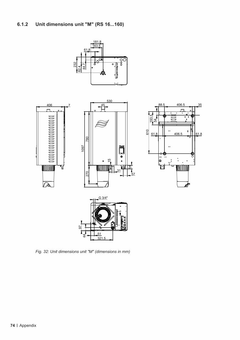
74 Appendix
Fig. 32: Unit dimensions unit "M" (dimensions in mm)
780
1097
270
53045
3157
15
54
88.5 35 406.5
61.8 61.8406.5
54193.
561
0
51321.544
97
61.8163.5181.8
44.7
82.423
2
G 3/4"
406 7
6.1.2 Unit dimensions unit "M" (RS 16...160)

75Appendix
Fig. 33: Unit dimensions unit "L" (dimensions in mm)
406 7
780
1097
270
100045 45
31 31 107
15
54
117 70406.5 406.5
164
263.
559
0
51321.5
408678.5
4497
178.8535.8
61.8163.5
418.8520.5
44.7
82.423
2
G 3/4" G 3/4"
6.1.3 Unit dimensions unit "L" (RS 50...80)

76 Appendix
6.2 EC Declaration of conformity

Notes

Notes


Condair Group AGTalstrasse 35-37, CH-8808 PfäffikonPhone +41 55 416 61 11, Fax +41 55 416 62 [email protected], www.condair.com
CONSULTING, SALES AND SERVICE:
CH94/0002.00