Embed Size (px)
Citation preview

Installation an servi e o t is re la e s oul e er or e uali e ersonnel Heart Ho e e nolo ies re o en s I erti e ro es-
sionals or te ni ians su ervise an I erti e ro essional
EPA CERTIFIED WOODBURNING FIREPLACE
Fire Risk.
WARNING
or use it soli oo uel onlt er uels a over re an enerate oisonous ases i e ar on ono i e
O-T LTested an d L isted b y
P ortl an dOreg on U SA
OM N I - Test L ab oratories, I n c.C U S
Model(s):
Installation ManualInstallation and Fireplace Setup
WARNINGHOT SURFACES!
lass an ot er sur a es are ot urin o eration D ool o n
Hot glass will cause burns.• DO NOT tou lass until it is oole• R allo il ren to tou lass• ee il ren a a
• C R R I il ren in sa e roo as re la e
• lert il ren an a ults to a ar s o i te eratures
High temperatures may ignite clothing or other flammable materials.• ee lot in urniture ra eries an ot er a a le
aterials a a
INSTALLER: Leave this manual with party responsible for use and operation.OWNER: Retain this manual for future reference.
C40
NOTICE: DO NOT discard this manual!
• DO NOT store or use asoline or ot er a -a le va ors an li ui s in t e vi init o t is
or an ot er a lian e• DO NOT over re ver rin ill voi our
arrant• Co l it all ini u learan es to o -
usti les as s e i e ailure to o l a ause ouse re
WARNING: If the information in these instructions is not followed exactly, a fire or explosion may result causing property damage, personal injury, or death.
1Heatilator • C40 Constitution • 480-2340 Installation Manual • Rev D • 05/30/13

Safety Alert Key:• DANGER! In i ates a a ar ous situation i i not avoi e ill result in eat or serious in ur• WARNING! In i ates a a ar ous situation i i not avoi e oul result in eat or serious in ur• CAUTION! In i ates a a ar ous situation i i not avoi e oul result in inor or o erate in ur• NOTICE: In i ates ra ti es i a ause a a e to t e re la e or to ro ert
Table of Contents1 Product Specific & Important Safety Information
ire la e Certi ation 4 lass e i ations 4
C on-Co usti le Materials 4D Co usti le Materials 4
le tri al Co es 5
2 Getting Started i al ire la e ste Desi n an Installation Consi erations 1 ele tin ire la e o ations 2 o atin ire la e C i ne 8
C ools an u lies ee e D Ins e t ire la e an Co onents
ire la e ste Re uire ents
3 Framing and Clearances ire la e Di ensions 10 Clearan es 111 Mini u Clearan es to Co usti les 122 Re u e Mantel Hei t / tional ra in Constru tion
Re uire 12C Constru t t e C ase 13D ra e t e ire la e 14
e ure an evel t e ire la e 14 rote tive Metal Heart tri s 15 a in Material 15
H utsi e ir it 1I Heat one it tional 18
4 Electrical Wiring 5 Chimney and Termination Requirements
C i ne Re uire ents 22 sets/Returns 23
C er ination Re uire ents 24
6 Chimney Installation i al C i ne ste 25 sse le C i ne e tions 2
C Install C i ne ir it C 4 2D e ure set/Return 28
Install Ceilin iresto s 28 Install tti Insulation iel 2 Roo enetration 30
H Manu a ture Ho e Installation 30I Install C ase/C ase o 31
er ination Ca Re uire ents 32 Install er ination Ca 32
7 Finishing e late 34 inis t e all 34
1 tone ri inis 342 ile ranite Mar le inis 34
C Mantel an all ro e tions 35D inis in t e Heart tension 35
on-Co usti le ealant Material 3
8 Fireplace Setup ire ri la e ent 38 a e an lan et la e ent 3
9 Reference Materials C i ne Co onents 40
2 Heatilator • C40 Constitution • 480-2340 Installation Manual • Rev D • 05/30/13

Customer:Lot/Address
Model (circle one): C40
Fireplace Install YES IF NO, WHY?eri ie t at t e ase is insulate an seale 13
Re uire non- o usti le oar is installe 15eri ie learan es to o usti les 11ire la e is levele an se ure 14
Heart e tension si e/ ei t e i e 14 3utsi e air it installe 1tional Heat one as een installe a uali ie servi e te ni ian 18
Chimney Section 5 (Pg. 22)C i ne on i uration o lies it ia ra sC i ne installe lo e an se ure in la e it ro er learan e
Roo las in installe an sealeer inations installe an seale
Electrical Section 4 (Pg. 21)it ires ro erl installe
Finishing Section 7 (Pg. 34)Co usti le aterials not installe in non- o usti le areas
Dealer/Distributor Phone #Serial #:
WARNING! Risk of Fire or Explosion! Failure to install fireplace acording to these instructions can lead to a fire or explosion.
iresto s installeC i ne air it installe
tti insulation s iel s installe
ATTENTION INSTALLER:Follow this Standard Work Checklist
is stan ar or e list is to e use t e installer in on u tion it not instea o t e instru tions ontaine in this installation anual
Date Installed:Location of Fireplace:Installer:
Co usti le aterials not installed in non- o usti le areaseri ie all learan es eet installation anual re uire ents
Mantels an all ro e tions o l it installation anual re uire entsrote tive eart stri s an eart e tension installe er anual re uire ents
Fireplace Setup Section 8 (Pg. 38)ll a a in an rote tive aterials re oveire ri a le an era i lan et installe orre tla ia an oors ro erl installe
ll a a in aterials are re ove ro insi e/un er t e ire la e
Hearth & Home Technologies recommends the following:• oto ra in t e installation an o in t is e list or our ile• at t is e list re ain visi le at all ti es on t e ire la e until t e installation is o lete
Co ents o uni ate to art res onsi le
art 401 -255 • Rev • 01/2 /13
on uil er/ en Contra tor Installer Date
Comments: urt er es ri tion o t e issues o is res onsi le Installer/ uil er/ t er ra es et an orre tive a tion nee e _________________________________________________________________________________________________
Manual a an all o its ontents are re ove ro insi e/un er t e ire la e an iven to t e art res onsi le or use an o eration
________________________________________________________________________________________________________________________________________________________________________________________________________________
3Heatilator • C40 Constitution • 480-2340 Installation Manual • Rev D • 05/30/13

1 Product Specific & Important Safety Information
A. Fireplace Certificationis re la e s ste as een teste an liste in a -
or an e it 12 an C- 10-M8 an M 84-H D stan ar s or installation an o eration in t e nite
tates an Cana a as es ri e in t is anual
C e it our lo al uil in o e a en e ore ou e in our installation to ensure o lian e it lo al o es in lu in t e nee or er its an ollo -u in-
s e tions e sure lo al uil in o es o not su erse e s e i ations an al a s o tain a uil in er it so
t at insuran e rote tion ene ts annot e une e te l an elle
Heatilator is a re istere tra e ar o Heart Ho e e nolo ies
C. Non-Combustible Materials• Materials i ill not i nite an urn o ose o
an o ination o t e ollo in- teel - Iron- ri - ile- Con rete - late- lass - lasters
• Materials re orte as assin ASTM E 136, Standard Test Method for Behavior of Metals, in a Vertical Tube Furnace at 750° C
D. Combustible Materials• Materials a e o or sur a e it an o t e ollo in
aterials- oo - Co resse a er- lant ers - lasti- l oo / - eet ro r all
• n aterial t at an i nite an urn a e roo e or not lastere or un- lastere
B. Glass Specificationsis re la e is e ui e it 5 era i lass Re-
la e lass onl it 5 era i lass lease onta t our ealer or re la e ent lass
NOTICE: This installation must conform with local codes. In the absence of local codes you must comply with the UL127, (UM) 84-HUD and NFPA211 in the U.S.A. and the ULC 610-M87 and CAN/CSA-B365 Installation Codes in Canada.
WARNING! Risk of Fire! Hearth & Home Technologies disclaims any responsibility for, and the warranty and agen-cy listing will be voided by the following actions.DO NOT:• installoroperatedamagedfireplace• modifyfireplace• install other than as instructed by Hearth & Home
Technologies• operate the fireplace without fully assembling all
components• overfire• installanygaslogset• installanycomponentnotapprovedbyHearth&Home
Technologies• installpartsorcomponentsnotListedorapprovedImproper installation, adjustment, alteration, service or maintenance can cause injury or property damage. For assistance or additional information, consult a qualifiedinstaller, service agency or your dealer.
Model: Constitution Certi e oo urnin ire la e
Laboratory: M I est a oratories InReport No: 0 1- -50-2Type: oo ire la eStandard: 12 an C- 10-M8 an
M 84-H D Manu a ture Ho e rove
EPA# and Original Date: 5 1 4-1-03
EPA Certified:3 25 ra s er our
Efficiency: u to
BTU Output with EPA test fuel: 51 400 / r
with Cord Wood: 0 000 / r
Heating Capacity: u to 3 500 s t
Chimney Size: 8 in es
HHT 300 eries
DuraVent Dura lus
Max Wood Length: 24 in es
Fuel: Cor oo
Shipping Weight: 50 l s
Firebox Size 2 u i eet
4 Heatilator • C40 Constitution • 480-2340 Installation Manual • Rev D • 05/30/13

E. Electrical Codes
NOTICE: This fireplacemust be electrically wired andgrounded in accordance with local codes or, in the absence of local codes, with National Electric Code ANSI/NFPA 70-latest edition or the Canadian Electric Code CSA C22.1.
• 110-120 C ir uit or t is ro u t ust e rote te it roun - ault ir uit-interru ter rote tion in o lian e it t e a li a le ele tri al o es en
it is installe in a lo ations
WARNING! Improper installation, adjustment, alteration, service or maintenance can cause injury or property dam-age.
5Heatilator • C40 Constitution • 480-2340 Installation Manual • Rev D • 05/30/13

2 Getting Started
N o n- c o m b u s t ib l er o o f f l a s h ing m a int a insm inim u m c l e a r a nc ea r o u nd c h im ne y
A d d it io na l l a t e r a ls u p p o r t f o r c h im ne ya b o v e r o o f ( o r e nc l o s e din c h a s e ) if ne e d e d
E nc l o s e d s p a c e a b o v ea nd a r o u nd f ir e p l a c e
S u p p o r t s t r a p so n r a f t e r s u p p o r t sc h im ne y ( no t s h o w n)
O u t s id ec o m b u s t io n a ir
O u t s id ec o m b u s t io n a ir
T e r m ina t io n C a p
C h im ne y p e ne t r a t e s r o o f p r e f e r a b l y w it h o u t a f f e c t ingr o o f r a f t e r s
S t o r m C o l l a r
O f f s e t /R e t u r n ( w it h h a ng e r s t r a p s )
A t t ic ins u l a t io n s h ie l d m u s t b e u s e d h e r e t o k e e p ins u l a t io n a w a y f r o m c h im ne y if a t t ic is ins u l a t e d
F r a m ing h e a d e d o f f in c e il ing j o is t s
M a nt e l
D e c o r a t iv e f a c inga nd t r im
F a c t o r y - b u il t f ir e p l a c e
C h im ne y s y s t e m
C o m b u s t ib l e f r a m ing /h e a d e ro n t o p o f V - s h a p e d s t a nd o f f s ( s p a c e r s )
H e a r t h e x t e ns io n
P r o t e c t iv e m e t a lh e a r t h s t r ip ( s )
A. Typical Fireplace System
Figure 2.1 Typical Fireplace System
Heatilator • C40 Constitution • 480-2340 Installation Manual • Rev D • 05/30/13

D
CA
E
F
AH
GB
A
B
B
AI
I n a n e x t e r io r c h a s e o r p r o j e c t ing int o a g a r a g e
A c r o s s a c o r ne r
A l o ng a w a l l
A s a r o o m d iv id e r
24 in. ( 61 0 m m )
24 in. ( 61 0 m m )
24 in. ( 61 0 m m )
48 in. ( 1 21 9 m m )
24 in. ( 61 0 m m )
I
A
Figure 2.2 Fireplace Locations
NOTICE:• Illustrationsandphotosreflecttypicalinstallationsand
are FOR DESIGN PURPOSES ONLY.• Illustrations/diagramsarenotdrawntoscale.• Actualinstallation/appearancemayvaryduetoindividual
design preference.• Hearth&HomeTechnologiesreservestherighttoalter
its products.
NOTICE: In addition to these framing dimensions, also reference the following section:
• Clearances (Section 3).
NOTICE: A minimum 1 in. air clearance at the back and a minimum 1 in. air clearance to the sides of the fireplaceassemblymustbemaintained.Chimney sections at any level require a 2 in. mini-mum air space clearance between the framing and chimney sections.
B. Design and Installation Considerations
NOTICE: Check building codes prior to installation.
• Installation M o l it lo al re ional state an national o es an re ulations
• Consult insuran e arrier lo al uil in ins e tor re o ials or aut orities avin uris i tion over restri tions installation ins e tion an er its
1. Selecting Fireplace Locationsis re la e a e use as a roo ivi er installe
alon a all a ross a orner or use in an e terior ase ee i ure 2 2
o atin t e re la e in a ase ent near re uentl o ene oors entral eat outlets or returns or ot er lo ations o onsi era le air ove ent an a e t t e
er or an e
utsi e air ust e use or o ustion e C40 o es e ui e it an outsi e air inlet to ee o ustion air ro outsi e t e o e alon it an outsi e air ter ina-tion a t e ri i etal u t is re uire ut not su lie Consi eration s oul e iven to t ese a tors e ore
e i in on a lo ation
Model # A B C D E F G H I
C40 i ensions or nis e alls
in. 41- /8 1 8 -1/2 3-5/1 22- /1 44-3/4 14-1/1 55-15/1 50- /8
mm 10 3 40 22 3 1 08 5 0 113 35 1421 12 2
Heatilator • C40 Constitution • 480-2340 Installation Manual • Rev D • 05/30/13

2. Locating Fireplace & Chimney
o ation o t e re la e an i ne ill a e t er or-an e
• Install it in t e ar airs a e en lose t e uil in envelo e is el s to ro u e ore ra t es e iall
urin li tin an ie- o n o t e re• enetrate t e i est art o t e roo is ini i es
t e e e ts o in loa in• o ate ter ination a a a ro trees a a ent
stru tures uneven roo lines an ot er o stru tions• Mini i e t e use o i ne o sets • Consi er t e re la e lo ation relative to oor an eilin
an atti oists• a e into onsi eration t e ter ination re uire ents in
e tions 5 an
M a r g ina l L o c a t io n:• Below peak
Location NOT recommended:• Not the highest point of the roof• Wind loading possible
Multi-level Roofs
Windward
Leeward
Recommended Location:• Above peak
Recommended:• Insulated exterior chase
in cooler climates
Recommended Location:• Above peak• Inside heated space
Location NOT recommended:• Too close to tree• Below adjacent structure• Lower roof line• Avoid outside wall
M a r g ina l L o c a t io n:• Wind loading possible
Figure 2.3 Recommended Chimney Locations
• Install t e outsi e air it it t e inta e a in revailin in s urin t e eatin season
• nsure a e uate out oor air or all o ustion a lian es an e aust e ui ent
• nsure urna e an air on itionin return vents are not lo ate in t e i e iate vi init o t e re la e
• voi installin t e re la e near oors al a s or s all isolate s a es
• Re esse li tin s oul e a seale an esi n• tti at es eat er stri e or seale• tti ounte u t or an air an ler oints an sea s
ta e or seale
8 Heatilator • C40 Constitution • 480-2340 Installation Manual • Rev D • 05/30/13

C. Tools and Supplies Needede ore e innin t e installation e sure t e ollo in
tools an uil in su lies are availa le
Re i ro atin sa ra in aterial
liers on- o usti le sealant
Ha er loves
illi s s re river ra in s uare
lat la e s re river le tri rill an its
lu line a et lasses
evel a e easure
1/2-3/4 in len t or 8 sel - rillin s re s
Mis s re s an nails
D. Inspect Fireplace and Components
WARNING! Risk of Fire and/or Explosion! Damaged parts could impair safe operation. DO NOT install dam-aged, incomplete or substitute components. Keep fire-place dry.
• Re ove re la e an o onents ro a a in an ins e t or a a e
• ent s ste o onents an oors are s i e in se arate a a es
• Re ort to our ealer an arts a a e in s i ent• Read all the instructions before starting the
installation. Follow these instructions carefully during the installation to ensure maximum safety and benefit.
E. Fireplace System Requirementse Heatilator re la e s ste re uire ents onsist o
t e ollo in
• ire la e- ire ri in lu e it re la e- Door in lu e it re la e- on- o usti le a in aterial in lu e it
re la e- Heart tension
• utsi e ir ste oo an ollars in lu e it re la e
• as ia• C i ne ste
- C i ne air it in lu e it re la e re uire it 300 series i ne
- tti Insulation iel in lu e it re la e- C i ne ter ination a
• on- o usti le nis aterial
tional o onents in lu e• ires reen• intel ar• Heat one it
Heatilator • C40 Constitution • 480-2340 Installation Manual • Rev D • 05/30/13

3 Framing and Clearances
A. Fireplace Dimensions
1 1 - 1 /8 in.( 28 3 m m )
23- 1 /8 in.( 5 8 7 m m )
31 - 1 /8 in.( 79 1 m m )
3- 1 /2 in.( 8 9 m m )
40 - 5 /1 6 in.( 1 0 24 m m )
43- 1 3/1 6 in.( 1 1 0 0 m m )
37 in.( 9 40 m m )
40 in.( 1 0 1 6 m m )
43 in.( 1 0 1 6 m m )
1 in.( 25 m m )
5 - 7/8 in.( 1 49 m m )
6- 1 /2 in.( 1 65 m m )
9 - 1 1 /1 6 in.( 246 m m )
F a n E l e c t r ic a l A c c e s s( r ig h t s id e o f f ir e p l a c e )
Figure 3.1 Fireplace Dimensions
10 Heatilator • C40 Constitution • 480-2340 Installation Manual • Rev D • 05/30/13

B. ClearancesWARNING! Risk of Fire!
YoumustcomplywithallminimumairspaceclearancestocombustiblesasspecifiedinFigure3.2.DO NOT pack required airspaceswithinsulationorothermaterials.Framingorfinishingmaterialusedonthefrontof,orinfrontof,thefireplacecloser than the minimums listed must be constucted entirely of non-combustible materials (i.e., steel studs, concrete board, etc.).Failuretocomplymaycausefire.
Figure 3.2 Clearances to Combustible Materials
2 in. ( 5 1 m m ) m in.
A t t ic I ns u l a t io n
S h ie l d
C e il ing F ir e s t o p
( c e il ing )
( r o o f )
( a t t ic )
( c e il ing )
C e il ing F ir e s t o p O f f s e t /R e t u r n w it h h a ng e r s t r a p s
S t o r m C o l l a r
R o o f F l a s h ing
2 in. ( 5 1 m m ) m in.
2 in. m in. ( 5 1 m m )
M u s t h a v e 2 in. ( 5 1 m m ) m inim u m c l e a r a nc e
t o h e a d e r
2 in. ( 5 1 m m ) m in.
2 in. ( 5 1 m m ) m in.
2 in. ( 5 1 m m ) m in.
1 in. ( 25 m m ) t o s id e o f a p p l ia nc e( e x c e p t a t na il ing f l a ng e s w h e r e it is 1 /2 in. [ 1 3 m m ] )
1 in. ( 25 m m ) t o b a c ko f a p p l ia nc e
0 in.t o f l o o r
0 in. t o l e v e lo f s t a nd o f f s
2 in.( 5 1 m m )
m in. 36 in. ( 9 1 4 m m )
s t a nd o f f s t o c e il ing
11Heatilator • C40 Constitution • 480-2340 Installation Manual • Rev D • 05/30/13

2. Reduced Mantel Height / Optional Framing Construction RequiredNon-combustible antel aterial ini u ei t ro ase o re la e to un ersi e o antel 4 in 11 8 en t e ollo in en losure onstru tion aterials are use
on- o usti le ra in aterials ust e use a ove re la e to ei t o 84 in 2134 or to t e eil-
in ro ase o re la e or all onstru tion aterials ra in e ers s eetin an all nis aterials
1. Minimum Clearances to Combustibles
WITHIN ENCLOSURE AREAire la e to a all 1/2 in 13 ire la e to si e all 1 in 25
Du t oots to ra in 0 in 0 o stan o s to ea er 0 in 0
Door o enin to si e all 22- /8 in 581 EXPOSED SURFACES
a e late to si e all 1 in 40 Heat one air rills to eilin 12 in 305 MANTELMantel ini u ei t 0 in 1524 Ma i u antel e t 12 in 305
P o s it io n c o m b u s t ib l e / no n- c o m b u s t ib l e m a nt e l60 in. ( 1 5 24 m m ) f r o m b a s e o f f ir e p l a c e
1 2 in.( 30 5 m m )
46- 1 /4 in.( 1 1 75 m m )
24 in.( 61 0 m m )
2 in.( 5 1 m m )
48 - 1 /4 in.( 1 226 m m )
42-1/4 in.( 1 0 73 m m )
The finished cavity depth must be no less than 24 in. (610 mm) from the finished backwall to the outside of front wall framing.
Figure 3.3 Framing the Fireplace
12 Heatilator • C40 Constitution • 480-2340 Installation Manual • Rev D • 05/30/13

C. Construct the Chase ase is a verti al o li e stru ture uilt to en lose t e re la e an /or its vent s ste erti al i ne s t at
run on t e outsi e o a uil in ust e installe insi e a ase
In ol li ates Heart Ho e e nolo ies re o -en s t at t e ase e ell insulate usin att t e
insulation et een t e oists
Constru tion o t e ase a var it t e t e o uil -in ese instru tions are not su stitutes or t e re uire-
ents o lo al uil in o es o al uil in o es M e e e
C ases s oul e onstru te in t e anner o all outsi e alls o t e o e to revent ol air ra tin ro le s e ase s oul not rea t e outsi e uil in envelo e
in an anner ll outer alls nee to e insulate
uil in o es re uire alse eilin an eilin resto s/atti s iel s at ea oor o t e ase or ever 10 t 3048
o lear s a e to ontrol s rea o re
alls eilin ase late an antilever oor at t e rst level o t e ase s oul e insulate see i ure 3 4
a or an air in ltration arriers s oul e installe in t e ase as er re ional o es or t e rest o t e o e -
itionall Heart Ho e e nolo ies re o en s t at t e insi e sur a es e r alle an ta e or t e use o an e uivalent et o or a i u air ti tness
Holes an ot er o enin s s oul e aul e it i te erature aul or stu e it un a e er lass insulation
Ceiling Firestop
Metal Chase Top
Round Termination Cap
False Ceiling
Insulation in the outside walls of the chase
Attic Insulation
Shield
Chimney
Ceiling Firestop
Tabs
False Ceiling False Ceiling Insulation Insulation
Storm Collar
Figure 3.4 Chase Assembly
1 2 3
A l l o u t s id e w a l l s s h o u l d b e ins u l a t e d .
Figure 3.5 Chase Constructions
1 ire la e an i ne en lose in an e terior ase 2 C i ne o set t rou e terior all an en lose in ase 3 C ase onstru te on roo
• e ase is onstru te usin ra in aterials u t e sa e as t e alls in our o e variet o si in
aterials a e use in lu in ri stone veneer ri or stan ar si in aterials
• In onstru tin t e ase several a tors ust e onsi ere
- Maintain a 2 in 51 air s a e aroun t e i ne
- e ase to ust e onstru te o non-o usti le aterial
- In ol li ates a resto s a er an atti insulation s iel s oul e installe in an insulate alse eilin at t e 8 t 2438 level a ove t e re la e asse l is re u es eat loss t rou t e ase
- In ol li ates t e alls o t e ase s oul e insulate to t e level o t e alse eilin as s o n in
i ure 3 4 is ill el re u e eat loss ro t e o e aroun t e re la e
ree e a les o ase a li ations are s o n in i -ure 3 5
WARNING! You must install false ceilings and ceil-ing firestops at each floor of the chase or every 10 ft (3.05 m) to control spread of fire.
WARNING! Risk of Fire! DO NOT sealareabetweenfirestop opening and chimney pipe except where they enter the attic or leave the warm air envelope of the home (use 600° F sealant).
WARNING! Risk of Fire! You must maintain a minimum 2 in. (51 mm) air space clearance to insulation and other materials surrounding the chimney system.• Insulationandothermaterialsmustbefirmlysecuredto
prevent accidental contact with chimney system.• Thechasemustbeproperlyblockedtopreventblown
insulation or other combustibles from entering and makingcontactwithfireplaceorchimney.
• Failuretopreventcontactbetweeninsulationorothermaterials and chimney system may cause overheating andfire.
13Heatilator • C40 Constitution • 480-2340 Installation Manual • Rev D • 05/30/13

D. Frame the Fireplace
NOTICE: Heart e tension esi n ust e eter ine e ore installation o re la e
I t e re la e is la e on t e oor t e a i u ei t o a nis e raise eart is 5-3/4 i ou ant a i er raise eart t e re la e ust e la e on a lat or
NOTICE: Wiring for fans must be done before framed enclosure is completed. If using a Heat Zone Kit, it also must be installed before enclosure is complete.
e C40 ire la e ill t a ra e o enin ei t o 4 -1/4 in 11 4 tall an 42-1/4 in 10 3 i e
WARNING! Risk of Fire! You must comply with all minimum air space clearances to combustibles. DO NOT pack required air spaces with insulation or other materi-als.
WARNING! Risk of Fire! Comply with all minimum clear-ancesspecified.• Aminimum 1 in. (25mm) air clearancemust be
maintained at the back and 1 in. (25 mm) to the sides ofthefireplaceassembly.
• Chimneysectionsatanylevelrequirea2in.(51mm)minimum air space clearance between the framing and chimney section.
i ure 3 3 s o s a t i al ra in usin 2 4 lu er o t e re la e assu in o usti le aterials are use ll re uire learan es to o usti les aroun t e re la e ust e a ere to ee i ure 3 2 n ra in
a ross t e to o t e re la e ust e a ove t e level o t e to stan o s o re ess a ove stan o s
The nis e avit e t ust e no less t an 24 in 10 ro t e nis e a all to t e outsi e o ront all ra in ra in ust e ten strai t u all t e a
to t e eilin
CAUTION! Risk of Cuts/Abrasions. Wear protective gloves and safety glasses during installation. Sheet metal edges are sharp.
WARNING! Risk of Fire! Prevent contact with sagging, loose insulation. • DO NOT install against vapor barriers or exposed
insulation.• Secureinsulationandvaporbarriers.• Provideminimumairspaceclearancesatthesidesand
backofthefireplaceassemblyasoutlinedinSection3.
E. Secure and Level the Fireplaceis re la e a e la e on eit er a o usti le or
non o usti le ontinuous at sur a e ollo t e in-stru tions or ra in in e tion 3 li e t e re la e into osition e sure to rovi e t e ini u 1 in air lear-
an e at t e si es an 1 in at t e a o t e re la e
e re la e s oul e ositione so t e a e o t e non-o usti le aterial on t e re la e ill e us it t e a e o t e r all on t e alls ee i ure 3
evel t e re la e an s i as ne essar
T h e se su r f a ce s m u st b e e ve n!
D r yw a l l N o n- co m b u st ib l ef a ci ng m a t e r ia l
Figure 3.6 Drywall - Non-combustible Facing Material
14 Heatilator • C40 Constitution • 480-2340 Installation Manual • Rev D • 05/30/13

1 in. ( 25 m m ) O v e r l a p
M e t a l s t r ip s 2 in. ( 5 1 m m ) u nd e r e d g e o f F ir e p l a c e a nd H e a r t h E x t e ns io n a nd e x t e nd e d 2 in. ( 5 1 m m ) b e y o nd b o t h s id e s o f f ir e p l a c e o p e ning .N a il o r s c r e w m e t a l s t r ip s in p l a c e .
P a l l e t M o u nt ing /F l o o r B r a c k e t s
R a is e d P l a t f o r m
F l o o r
2 in.( 5 1 m m )
1 in. ( 25 m m ) m in.o v e r l a p
2 in.( 5 1 m m )
T o p p ie c e m u s t o v e r l a pb o t t o m p ie c e
Figure 3.8 Protect the Front of an Elevated Platform
F. Protective Metal Hearth Strips
Figure 3.7 Position the Protective Metal Hearth Strips
• o ate t e t o rote tive etal eart stri s easurin a ro i atel 2 in 4 in 0 102 in lu e
it t is re la e• li e ea etal stri 2 in 51 un er ront e e o
re la e• verla stri s in t e i le o re la e o enin 1 in
25 ini u• Metal stri s ust e ten e on t e ront an si es
o t e re la e o enin at least 2 in 51 i ure 3
• rote t t e ront o a lat or elevate a ove t e eart e tension it etal stri s not in lu e it re la e
er i ure 3 8 ee e tion or eart e tension instru tions
WARNING! Risk of Fire! Protective metal hearth strips MUST be installed on combustible surfaces. DO NOT cover metal strips with combustible materials. Sparksorembersmayigniteflooring.
WARNING! Risk of fire! High temperatures, sparks, embers or other burning material falling from the fireplacemayigniteflooringorconcealedcombustiblesurfaces.• ProtectivemetalhearthstripsMUSTbeinstalled.• Hearth extensionsMUSTbe installed exactly as
specified.
WARNING! Risk of Fire!Follow these instructions exactly.Facing materials must be installed properly to prevent fire.No materials may be substituted without authorization by Hearth & Home Technologies
G. Facing Material
TOOLS NEEDED: o ere rill it 2 illi s ea it aul in unnl non- o usti le aterials su lie it re la e a e use to over t e etal re la e ront
NOTE: All boards are pre-drilled for your convenience. Boards MUST be attached in the following order: bottom, top, and then the two sides, red-painted side out. The top and bottom board should each have a hang tag attached. Leave them attached for referral for the finishingoperation.
• tta t e otto oar to t e otto o t e outer re la e an it en lose s re s ensurin t e oar
is entere DO NOT remove hang tags• Center an atta t e to oar to t e outer an an
ra in e ers DO NOT remove hang tags.• sin t e u er Calsti run a li t ea 1/8 in
ini u et een t e etal sur a e o t e re la e an t e utt e es o t e to oar ee i ure 3
• nsurin t e to o t e si e ie es an t e to oar ali n atta t e si e ie es to t e outer an an ra in
e ers
Figure 3.9 Apply Non-combustible Materials
Side Board
Bottom Board
Side Board
Top Board
DO NOT remove hang
tags
Apply bead of Super Calstick to
edge here
NOTICE: 1/8 in. of the facing material may be visible afterfinishingmaterialsareapplied.This1/8 in.mustbe painted or the red will show.
15Heatilator • C40 Constitution • 480-2340 Installation Manual • Rev D • 05/30/13
►

H. Outside Air Kitn outsi e air it ust e use or o ustion Heart
Ho e e nolo ies re o en s ou utili e t e s ortest u t run to o ti i e t e er or an e o t e outsi e air it e outsi e air inlet oo s oul e ositione in a anner t at ill not allo sno leaves et to lo t e
inlet In so e installations t e air u t a nee to e run verti all In su an installation a 3 t 14 ei t
i eren e ust e aintaine ro t e to o t e u er-ost i ne se tion to t e outsi e air inlet oo
Re er to i ures 3 10 an 3 11 en la in t e outsi e air inlet oo
e outsi e air it is installe on t e ri t an si e o t e re la e ee i ure 3 12 or an le lo ation/o eration
• Cut a in 152 ole in outsi e all to a o o ate air i in
• se in 152 etal e or ri i i in not su lie to ire tl onne t outsi e air to re la e inta e Insulate t e i e to revent rost on ensation
• se t e su lie outsi e air inlet oo• eal et een t e all an t e i e it sili one to
revent oisture enetration an air lea s• eal et een t e outsi e air inlet oo an t e ouse
it sili one to revent air in ltration
CAUTION! Risk of Cuts/Abrasions. Wear protective gloves and safety glasses during installation. Sheet metal edges are sharp.
CAUTION! Risk of Fire or Asphyxiation! DO NOT draw outsidecombustionairfromwall,floororceilingcavity,orenclosed spaces such as an attic or garage. • DO NOT place outside air inlet hood close to exhaust
vents or chimneys. Fumes or odor could be drawn into theroomthroughthefireplace.
• Locateoutsideairinlethoodtopreventblockagefromleaves, snow/ice, or other debris. Blockages could cause combustion air starvation.
A t t ic ins u l a t io n s h ie l dm u s t b e u s e d t o k e e pins u l a t io n a w a y f r o mc h im ne y .
C e il ing f ir e s t o po n f l o o r o f a t t ic .
3 f t m in. f r o m t o p o fu p p e r m o s t c h im ne y s e c t io n t o a ir inl e t .
Figure 3.10 Outside Air Inlet Locations
1 Heatilator • C40 Constitution • 480-2340 Installation Manual • Rev D • 05/30/13

O u t l e t b l o c k e d b ys no w , l e a v e s , e t c .
N O
G a r a g e o rc o m b u s t ib l e
l iq u id s s t o r a g e
N O
A t t ic s p a c eN O
O u t l e t p l a c e dh ig h e r t h a n 3 f t
b e l o w t h et e r m ina t io n c a p
N O
U s e o nl y d u c t m a t e r ia l s s p e c if ie d b y m a nu f a c t u r e r
Figure 3.11 Outside Air Installation
Figure 3.12 Outside Air
T e r m ina t io n C a p s u p p l ie d w it h
f ir e p l a c e 6 in. ( 1 5 2m m ) m e t a l f l e x o r r ig id p ip e
O p e n/C l o s e K no b f o r
o u t s id e a ir C L O S E O P E N
1Heatilator • C40 Constitution • 480-2340 Installation Manual • Rev D • 05/30/13
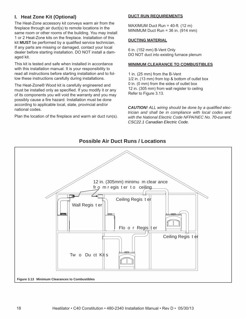
DUCT RUN REQUIREMENTS
M IM M Du t Run 40- t 12 MI IM M Du t Run 3 in 14
DUCTING MATERIAL
in 152 - ent nlD u t into e istin urna e lenu
MINIMUM CLEARANCE TO COMBUSTIBLES
1 in 25 ro t e - ent1/2 in 13 ro to otto o outlet o0 in 0 ro t e si es o outlet o12 in 305 ro all re ister to eilin Re er to i ure 3 13
CAUTION! ALLwiringshouldbedonebyaqualifiedelec-trician and shall be in compliance with local codes and with the National Electric Code NFPA/NEC No. 70-current. CSC22.1 Canadian Electric Code.
Possible Air Duct Runs / Locations
Figure 3.13 Minimum Clearances to Combustibles
C e il ing R e g is t e rW a l l R e g is t e r
F l o o r R e g is t e r
T w o D u c t K it s
C e il ing R e g is t e r
1 2 in. ( 30 5 m m ) m inim u m c l e a r a nc e f r o m r e g is t e r t o c e il ing
I. Heat Zone Kit (Optional)e Heat- one a essor it onve s ar air ro t e
re la e t rou air u t s to re ote lo ations in t e sa e roo or ot er roo s o t e uil in ou a install 1 or 2 Heat- one its on t e re la e Installation o t is it MUST e er or e a uali e servi e te ni ian
I an arts are issin or a a e onta t our lo al ealer e ore startin installation D install a a -
a e it
is it is teste an sa e en installe in a or an e it t is installation anual It is our res onsi ilit to
rea all instru tions e ore startin installation an to ol-lo t ese instru tions are ull urin installations
e Heat- one oo it is are ull en ineere an ust e installe onl as s e i e I ou o i it or an
o its o onents ou ill voi t e arrant an ou a ossi l ause a re a ar Installation ust e one
a or in to a li a le lo al state rovin ial an /or national o es
lan t e lo ation o t e re la e an ar air u t run s
18 Heatilator • C40 Constitution • 480-2340 Installation Manual • Rev D • 05/30/13

Installation• Re ove t e no out or over late ro t e to o t e
re la e an is ar it ee i ure 3 14• Cut a 3 in ole in t e insulation oar as er
t e i ensions s o n in i ure 3 14
A d a p t e r
M o u nt ing P l a t e
S t a r t e r P ip e
K no c k o u t
C u t a 3 in. ( 76 m m )
h o l e in ins u l a t io n b o a r d
3- 1 3/ 1 6 in. (9 7 mm)
3- 1 / 8 in. (7 9 mm)
C L
Run Length Cut Pipe20 - 40 ft (6-12 m) 2 in. (51 mm)*
*A minimum of 2 in. (51 mm) pipe must be used to cover the raw insulation to prevent it from blowing out through the return air grille.
10 - 20 ft (3 - 6 m) 8 in. (203 mm) 3 - 10 ft (1 - 3 m) No cut needed**
**Use full 16 in. (406 mm) as supplied
• Deter ine t e ne essar len t o starter i e ro t e a le 3 1 an ut as re uire
Figure 3.14
• li e t e starter i e into t e re la e at in t e oles in t e late to t e oles in t e re la e
• la e t e a a ter on t e ountin late linin u oles sin our s eet etal s re s in lu e in t e it se ure
t e a a ter an ountin late into re la e ter se urin to t e re la e ta e o n t e a a ter e es to t e to o t e re la e it alu inu ta e to revent lea a e
• Deter ine t e lo ation or t e air re ister an an ousin asse l Cut a -5/8 in 13-5/8 in 143 34 ole et een ra in e ers all stu s
or oor oists e ra ets an e rotate 180 an ounte to t e a si e o t e 2 4 i ne essar ee i ure 3 1
NOTICE: The fan and electrical connections must be accessible for servicing per local code requirements.
NOTICE: If the fan housing is installed in a 2 x 4 wall, the front of the housing will protrude approximately 1/4 in.(6mm)fromthefinishedwall.
• tta enou in 152 - ent as re uire or our installation to t e an ousin A maximum of (4)
90° elbows is recommended. e urel t ist lo t e - ent to t e a a ter
lso s re t e - ent to t e outlet o on t e an ousin ee i ure 3 1 u ort u t at intervals
o no reater t an 4 t 1 as re uire lo al o e
Figure 3.15
WARNING! Risk of Fire! Comply with all minimum clearancesspecified.• A minimum 1 in. (13 mm) air clearance must be
maintained at the back and 1 in. (25mm) to the sides ofthefireplaceassembly.
NOTE: It is important the pipe length be adhered to or it will affect the performance of your fireplace.
• n t e ountin late an en t e ta s o n ar li e t e ta s over t e outsi e o t e starter i e e ure it our s eet etal s re s in lu e in asteners a a e i ure 3 15
Table 3.1
1Heatilator • C40 Constitution • 480-2340 Installation Manual • Rev D • 05/30/13
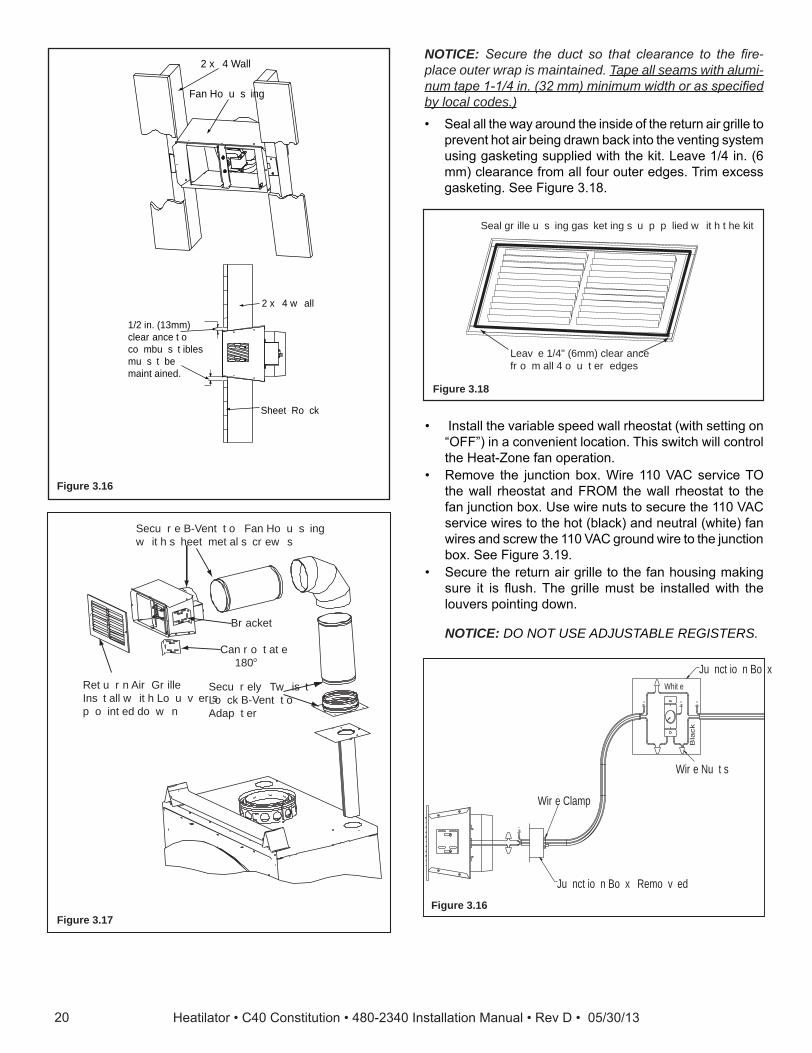
S e c u r e l y T w is t L o c k B - V e nt t o A d a p t e r
S e c u r e B - V e nt t o F a n H o u s ing w it h s h e e t m e t a l s c r e w s
R e t u r n A ir G r il l eI ns t a l l w it h L o u v e r s p o int e d d o w n
B r a c k e t
C a n r o t a t e 1 8 0 o
2 x 4 W a l l
F a n H o u s ing
1 /2 in. ( 1 3m m )c l e a r a nc e t oc o m b u s t ib l e sm u s t b em a int a ine d .
2 x 4 w a l l
S h e e t R o c k
L e a v e 1 /4" ( 6m m ) c l e a r a nc e f r o m a l l 4 o u t e r e d g e s
S e a l g r il l e u s ing g a s k e t ing s u p p l ie d w it h t h e k it
• Install t e varia le s ee all r eostat it settin on in a onvenient lo ation is s it ill ontrol
t e Heat- one an o eration• Re ove t e un tion o ire 110 C servi e
t e all r eostat an R M t e all r eostat to t e an un tion o se ire nuts to se ure t e 110 C servi e ires to t e ot la an neutral ite an
ires an s re t e 110 C roun ire to t e un tion o ee i ure 3 1
• e ure t e return air rille to t e an ousin a in sure it is us e rille ust e installe it t e louvers ointin o n
NOTICE: DO NOT USE ADJUSTABLE REGISTERS.
J u nc t io n B o x R e m o v e d
W ir e C l a m p
W ir e N u t s
J u nc t io n B o x
Bla
ck
W h it e
NOTICE: Secure the duct so that clearance to the fire-place outer wrap is maintained. Tape all seams with alumi-numtape1-1/4in.(32mm)minimumwidthorasspecifiedby local codes.)• eal all t e a aroun t e insi e o t e return air rille to
revent ot air ein ra n a into t e ventin s ste usin as etin su lie it t e it eave 1/4 in
learan e ro all our outer e es ri e ess as etin ee i ure 3 18
Figure 3.16
Figure 3.17
Figure 3.18
Figure 3.16
20 Heatilator • C40 Constitution • 480-2340 Installation Manual • Rev D • 05/30/13

1 4- 2 w /g r o u nd
S t a nd a r d w a l l m o u nt w it h J u nc t io n B o x
1 4- 3 w /g r o u nd
W I R E N U T
W H I T E
G R E E N
B L A C K
BLAC
K
R E D
W H I T EM a t c h c o l o r s t o w ir e h a r ne s s ( r e d t o r e d , w h it e t o w h it e , e t c ) a nd s e c u r e w it h a w ir e nu t
I nc o m ing P o w e r( 1 1 0 V )
P o w e r t o t h e F ir e p l a c eS na p D is c b y p a s s s w it c h
Figure 4.1 Fan Wiring Diagram
NOTICE: The manual override switch, rheostat speed control and cover plate are supplied. You will need to supply: 14-3 wire with ground; 14-2 wire with ground; standard wall mount junction box; wire nuts.
• Re ove un tion o over late on t e otto ri t si e o t e re la e
• rea t e 14-3 it roun ire t rou t e o enin it t e strain relie on t e over late
• Mat olors to ire arness re to re ite to ite et an se ure it ire nuts
WARNING! Risk of Fire! DO NOT applycombustiblefin-ishingmaterialsoveranypartofthefrontofthisfireplace.• Themetal fireplace facemay only be coveredwith
noncombustible materials such as ceramic tile, brick, or stone.
• Donotcoverorblockanycoolingairslots.
NOTICE: Wiring for fans must be done before framed enclosure is completed. If using a Heat Zone kit, it also must be installed before enclosure is complete.
4 Electrical Wiring
21Heatilator • C40 Constitution • 480-2340 Installation Manual • Rev D • 05/30/13

6 f t ( 1 .8 m ) m a x .u ns u p p o r t e dr u n
20 f t ( 6.1 0 m ) m a x .p ip e b e t w e e n a no f f s e t & r e t u r n
C e il ing f ir e s t o p
35 f t ( 1 0 .7 m ) m a x . s t r a ig h t u ns u p p o r t e d
c h im ne y h e ig h t
1 4.5 f t ( 4.42 m ) m in. h e ig h t /s ing l e o f f s e t - r e t u r n20 f t . ( 6.1 0 m ) m in. h e ig h t /d o u b l e o f f s e t - r e t u r n
5 0 f t ( 1 5 .24 m ) m a x . h e ig h t
6 f t ( 1 .8 3 m ) m a x .u ns u p p o r t e d c h im ne ya b o v e r o o f
44 in.( 1 1 1 8 m m )t o t o p o f s t a nd o f f s
A t t ic I ns u l a t io n S h ie l d
Figure 5.1 Chimney Requirements
NOTICE: A maximum of two pairs of offsets and returns may be used.
Minimum overall straight height 13 ft 3.96 mMinimum height with single offset/return
14.5 ft 4.42 m
Double offset/return minimum height 20 ft 6.1 mMaximum height 50 ft 15.24 mMaximum chimney length between an offset and return
20 ft 6.1 m
Maximum distance between chimney stabilizers
35 ft 10.67 m
Maximum unsupported chimney length between the offset and return
6 ft 1.83 m
Maximum unsupported chimney heightabovethefireplace
35 ft 10.67 m
Maximum unsupported chimney above roof
6 ft 1.83 m
WARNING! Risk of Fire! You must maintain 2 in. (51 mm) air space clearance to insulation and other combustible materials around the chimney system. Failure to do so maycauseoverheatingandfire.
NOTICE: You must provide support for the pipe during construction and check to be sure inadvertent loading has notdislodgedthechimneysectionfromthefireplaceoratany chimney joint.
A. Chimney Requirementserti al istan es are easure ro t e ase o t e re la e as s o n in i ure 5 1
5 Chimney and Termination Requirements
Table 5.2 Chimney Component DimensionsTable 5.1 Chimney Requirements
HEIGHT OF CHIMNEY COMPONENTS in. mm
Chimney Stabilizer
3 4-3/4 121
Offsets/Returns
315 13-3/8 340
330 15-1/2 3 4
Chimney Sections*
30 4-3/4 121
312 10-3/4 2 3
318 1 -3/4 425
324 22-3/4 5 8
33 34-3/4 883
348 4 -3/4 118
* Dimensions reflect effective height.
22 Heatilator • C40 Constitution • 480-2340 Installation Manual • Rev D • 05/30/13

Table 5.3 Offset Dimensions
B. Offsets/Returns• se an o set/return to ass over ea o stru tions• n o set an return an e use as a sin le entit or se arate i ne se tion s
WARNING! Risk of Fire! DO NOT use offset/returns greater than 30°. Chimney draft will be restricted and could cause overheatingandfire.Secureoffsetswithscrews(nottoexceed1/2”/13mminlength)Securereturnswithstrapping.Straight chimney sections may be secured with screws. Keep chimney sections from separating or twisting.
• Measure t e s i t nee e to avoi t e over ea o stru tion Re er to i ension in i ure 5 2• in t e a ro riate i ension liste in a le 5 3 e i ension oin i in it t e i ension easure ent in
a le 5 3 re resents t e re uire verti al learan e nee e to o lete t e o set/return• Rea a ross t e art to n t e nu er o i ne se tions/ o el nu ers nee e et een t e o set an return
A
B
1 - 1 /4 in. ( 32 m m )O V E R L A P
Figure 5.2 Chimney Offset/Return
Example: our i ension ro i ure 5 2 is 14-1/2 in 3 8
sin a le 5 3 t e i ension losest to ut not less t an 14-1/2 in 3 8 is 14-1/2 in 3 8 us-in a 30 o set/return
ou eter ine ro t e ta le t at ou nee 34-1/8 in 8 Di ension et een t e o set an return
e i ne o onent t at est ts our a li ation is one 324
15-degree 30-degree
SL306 SL312 SL318 SL324 SL336 SL348A B A B
in. mm in. mm in. mm in. mm
1 5/8 41 13 3/8 340 3 5/8 2 15 1/2 3 4 - - - - - -
2 /8 3 1 3/4 451 5 1/2 140 18 5/8 4 3 1 - - - - -
4 1/8 102 22 3/8 5 8 1/4 184 21 3/4 552 2 - - - - -
4 1/2 114 23 5/8 00 8 1/2 21 23 3/4 03 - 1 - - - -
5 3/4 14 28 1/4 18 10 1/4 2 0 2 8 1 1 - - - -
152 2 3/8 4 11 1/2 2 2 2 3 - - 1 - - -
1/4 184 34 8 4 13 1/4 33 32 1/8 81 - 2 - - - -
3/4 1 3 1/8 18 14 1/2 3 8 34 1/8 8 - - - 1 - -
8 3/4 222 3 3/4 1010 1 1/4 413 3 3/8 4 1 - - 1 - -
10 3/8 2 4 45 5/8 115 1 1/4 48 42 1/2 1080 - - 2 - - -
10 5/8 2 0 4 3/4 118 20 1/2 521 44 5/8 1133 - - - - 1 -
11 /8 302 51 3/8 1305 22 1/4 5 5 4 3/4 1213 1 - - - 1 -
13 1/2 243 5 1/4 1454 25 1/4 41 52 /8 1343 - - - 2 - -
13 3/4 34 58 3/8 1483 2 1/2 3 55 13 - - - - - 1
15 381 3 1 00 28 1/4 18 58 1/8 14 1 - - - - 1
1 1/2 41 8 3/4 1 4 31 1/4 4 3 1/4 1 0 - 1 - - - 1
18 45 4 5/8 18 5 34 1/4 8 0 8 1/2 1 40 - - 1 - - 1
1 5/8 4 8 80 3/8 2042 3 1/4 4 3 3/4 18 3 - - - 1 - 1
20 5/8 524 84 1/8 213 3 1/8 4 /8 1 53 1 - - 1 - 1
22 3/4 5 8 1 /8 2334 43 1/4 10 84 1/8 213 - - - - 1 1
24 10 1/2 2451 45 1/8 114 8 1/4 221 1 - - - 1 1
25 /8 5 103 1/2 2 2 4 1/4 1251 4 1/2 2400 - - - - - 2
ro er asse l o air- oole i ne arts result in an overla at i ne oints o 1-1/4 in 32 e tive len t is uilt into t is art
23Heatilator • C40 Constitution • 480-2340 Installation Manual • Rev D • 05/30/13

Sl an ted R oof s
F l at R oof s
C h im ne y m u s te x t e nd 3 f t ( .9 m )a b o v e t h e r o o f
C h im ne y m u s t e x t e nd 2 f t ( .6 m )a b o v e a ny p o r t io n o f t h e r o o f o ra d j a c e nt s t r u c t u r e s w it h in 1 0 f t ( 3 m ) o f t h e c h im ne y
C h im ne y m u s te x t e nd 3 f t ( .9 m )a b o v e t h e r o o f
C h im ne y m u s t e x t e nd 2 f t ( .6 m )a b o v e a ny p o r t io n o f t h e r o o f o ra d j a c e nt s t r u c t u r e s w it h in1 0 f t ( 3 m ) o f t h e c h im ne y
M u l tipl e Ch im n ey L ocation s
A B6 in. ( m inim u m ) u p t o 20 in.
152 mm/508 mm1 8 in. m inim u m
457 mm20 in. a nd o v e r 0 in. m inim u m
G a s , W o o d o r F u e l O ilT e r m ina t io n C a p
W o o dM inim u m
( S e eil l u s t r a t io n
a b o v e )
B
G a sT e r m ina t io n
C a p * *
A *
Per
pend
icul
ar W
all
* I f u s ing d e c o r a t iv e c a p c o v e r ( s ) , t h is d is t a nc e m a y ne e d t o b e inc r e a s e d . R e f e r t o t h e ins t a l l a t io n ins t r u c t io ns s u p p l ie d w it h t h e d e c o r a t iv e c a p c o v e r .
* * I n a s t a g g e r e d ins t a l l a t io n w it h b o t h g a s a nd w o o d t e r m ina t io ns , t h e w o o d t e r m ina t io n c a p m u s t b e h ig h e r t h a n t h e g a s t e r m ina t io n c a p .
Figure 5.3 Multiple Chimney Locations
C. Termination Requirements• Install a a a rove an liste or t is re la e s ste• o ate a ere it ill not e o e lu e sno or ot er aterials• o ate a a a ro trees or ot er stru tures• e otto o t e ter ination a ust e at least 3 t 1 a ove t e roo D at least 2 t 1 a ove an ortion
o roo it in 10 t 3 05 as s o n in i ure 5 3 • e istan e re uire et een a s is s o n in i ure 5 3
24 Heatilator • C40 Constitution • 480-2340 Installation Manual • Rev D • 05/30/13

6 Chimney Installation
T e r m ina t io n C a p
A d d it io na ls u p p o r t f o rt a l l c h im ne y s
S t o r m C o l l a r
M a int a in m inim u mc l e a r a nc e s t o c o m b u s t ib l e s a ss p e c if ie d
C h im ne y m u s t e x t e ndb e y o nd c o m b u s t ib l er o o f s t r u c t u r e
M a int a in m inim u mh e ig h t o f c h im ne ya b o v e r o o f
I ns t a l l r o o f f l a s h inga c c o r d ing t o m inim u mr e q u ir e m e nt s
O f f s e t s /r e t u r nsm a y no t e x c e e d30 ° f r o m v e r t ic a l S u p p o r t s t r a p s f o r o f f s e t s /
r e t u r ns m u s t b e s e c u r e dt o a d e q u a t e f r a m ing
C e il ing f ir e s t o p sa r e r e q u ir e d w h e r ec h im ne y p a s s e s t h r o u g h c e il ing o rf l o o r
A t t ic S h ie l d isr e q u ir e d w h e r e c h im ne yp a s s e s t h r o u g h a t t ic
Figure 6.1 Typical Chimney System - Guidelines for Chimney System Installation
NOTICE: Chimney performance may vary.
• Trees,buildings,rooflinesandwindconditionsaffectperformance.• Chimneyheightmayneedadjustmentifsmokingoroverdraftoccurs.
A. Typical Chimney System
25Heatilator • C40 Constitution • 480-2340 Installation Manual • Rev D • 05/30/13
A t t a c h F l u e F ir s t
C A K 4A
S e c u r e w it h S c r e w s P r o v id e d
P u s h T o g e t h e rS e c u r e t o T o p
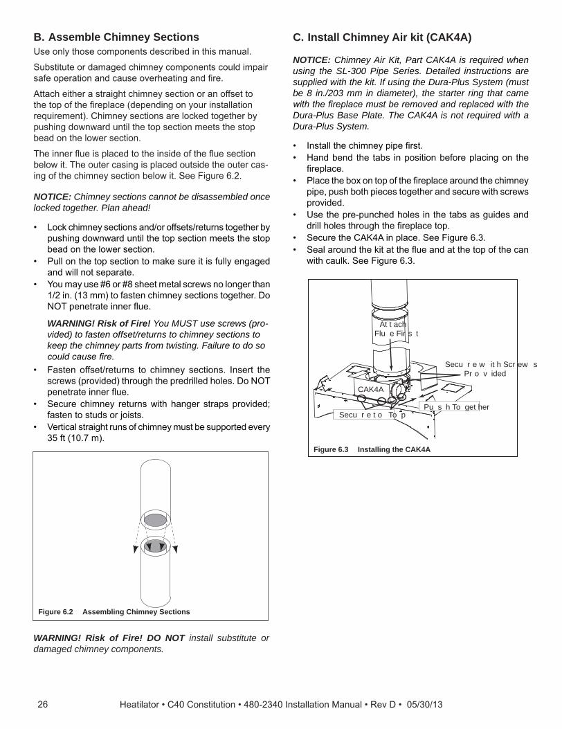
C. Install Chimney Air kit (CAK4A)
NOTICE: Chimney Air Kit, Part CAK4A is required when using the SL-300 Pipe Series. Detailed instructions are supplied with the kit. If using the Dura-Plus System (must be 8 in./203 mm in diameter), the starter ring that came withthefireplacemustberemovedandreplacedwiththeDura-Plus Base Plate. The CAK4A is not required with a Dura-Plus System.
• Install t e i ne i e rst• Han en t e ta s in osition e ore la in on t e
re la e• la e t e o on to o t e re la e aroun t e i ne
i e us ot ie es to et er an se ure it s re s rovi e
• se t e re- un e oles in t e ta s as ui es an rill oles t rou t e re la e to
• e ure t e C 4 in la e ee i ure 3• eal aroun t e it at t e ue an at t e to o t e an
it aul ee i ure 3
Figure 6.3 Installing the CAK4A
NOTICE: Chimney sections cannot be disassembled once locked together. Plan ahead!
• o i ne se tions an /or o sets/returns to et er us in o n ar until t e to se tion eets t e sto ea on t e lo er se tion
• ull on t e to se tion to a e sure it is ull en a e an ill not se arate
• ou a use or 8 s eet etal s re s no lon er t an 1/2 in 13 to asten i ne se tions to et er Do
enetrate inner ue
WARNING! Risk of Fire! You MUST use screws (pro-vided) to fasten offset/returns to chimney sections to keep the chimney parts from twisting. Failure to do so couldcausefire.
• asten o set/returns to i ne se tions Insert t e s re s rovi e t rou t e re rille oles Do
enetrate inner ue• e ure i ne returns it an er stra s rovi e
asten to stu s or oists• erti al strai t runs o i ne ust e su orte ever
35 t 10
B. Assemble Chimney Sections se onl t ose o onents es ri e in t is anual
u stitute or a a e i ne o onents oul i air sa e o eration an ause over eatin an re
tta eit er a strai t i ne se tion or an o set to t e to o t e re la e e en in on our installation re uire ent C i ne se tions are lo e to et er
us in o n ar until t e to se tion eets t e sto ea on t e lo er se tion
e inner ue is la e to t e insi e o t e ue se tion elo it e outer asin is la e outsi e t e outer as-
in o t e i ne se tion elo it ee i ure 2
WARNING! Risk of Fire! DO NOT install substitute or damaged chimney components.
Figure 6.2 Assembling Chimney Sections
2 Heatilator • C40 Constitution • 480-2340 Installation Manual • Rev D • 05/30/13

NOTES: • e C 4 ter ination a ust e a ini u o 4 t
121 a ove t e roun an e t ree o e ris • I t e C 4 is installe in a ase t e C 4 si e
ter ination a ust e at least 3 t 14 elo t e i ne to
• eal aroun t e a an e it aul to sto air ro ettin into t e ase see i ures 4
W ir e T ie s
4" F l e x
Seal
Seal
Figure 6.4 Installing Flex Pipe
WARNING! Risk of Fire!• Theflexpipemustneverbecompressedordeformed!• Restrictingtheairflowinsidetheflexpipemayincrease
fluepipetemperaturescausingachasefire.
2Heatilator • C40 Constitution • 480-2340 Installation Manual • Rev D • 05/30/13

D. Secure Offset/Return
E. Install Ceiling Firestops CAUTION! Risk of Fire! Ceilingfirestopsmustbeused
wheneverthechimneypenetratesaceiling/floor.• Chaseconstructionrequiresceilingfirestopsateach
floororevery10ft.(3.05m)ofclearspace.• Theceilingfirestopslowsspreadoffireandreduces
coldairinfiltration.
• Install a eilin resto enever i ne enetrates eilin / oor
• Mar an ut an o enin in eilin as s o n in i ure • ra e t e o enin it t e sa e si e lu er use in
t e eilin oists• ail t e eilin resto to t e otto o t e eilin oists
en t ere is a roo a ove• se an atti insulation s iel i t e eilin is insulate
e eilin resto a t en e atta e a ove or elo t e oists
R O O M A B O V E ( no n- ins u l a t e d c e il ing )
A T T I C A B O V E ( ins u l a t e d c e il ing )
B A
C e il ng f ir e s t o p a t t a c h e d t o b o t t o m
o f f r a m ing
C e il ing f ir e s t o p a t t a c h e d t o t o p o f
f r a m ing
N ote: U s e s a m e d im e ns io na l l u m b e r f o r f r a m ing c e il ing f ir e s t o p a nd j o is t s .
2 in. ( 5 1 m m ) c l e a r a nc e
2 in. ( 5 1 m m ) c l e a r a nc e
WARNING! Risk of Fire! DO NOT seal area between firestopopeningandchimneypipeexceptwheretheyen-ter the attic or leave the warm air envelope of the home (use 600° F sealant).
Figure 6.6 Installing the Ceiling Firestop
en o sets an returns are oine to strai t i e se -tions t e ust e lo e into osition it t e s re s
rovi e outer onl usin t e re rille oles o re-vent ravit ro ullin t e i ne se tions a art t e returns an t e i ne sta ili ers ave an er stra s or se urin t ese arts to oists or ra ters ee i ure 5
se or 8 s eet etal s re or lar er no lon er t an 1/2 in 13
WARNING! Risk of Fire!• Secureoffsetswithscrews(nottoexceed1/2in./13mm
In length).• Securereturnswithstrapping.• Straightchimneysectionsmaybesecuredwithscrew
(not to exceed 1/2 in./13 mm In length) at the joints.• Keepchimneysectionsfromseparatingortwisting.
C e il ingF ir e s t o p
S t r a p s
O p t io na lA d d it io na lS u p p o r t
J o intB a nd
( O p t io na l )
Figure 6.5 Secure the Chimney
Catalog #A B
in. mm in. mm
338 14-1/2 3 8 14-1/2 3 8
33 14-1/2 3 8 18-3/8 4
340 14-1/2 3 8 23 584
28 Heatilator • C40 Constitution • 480-2340 Installation Manual • Rev D • 05/30/13

Installation o a eilin resto is re uire
• Re er to i ures 8 • Roll t e s iel aroun t e i ne i alrea installe
until ou ave a 3 in overla an t e t ree oles on ea si e at u lar e oles on to
• Insert t ree s re s into t e at in oles to or a tu e
• en t ree ta s on t e otto o t e tu e in ar to 0 to aintain i ne air s a e re er to i ure 8
• Rest t e insulation s iel on t e eilin resto elo• en t e t ree s ort ta s at t e to o t e s iel in ar
to 0 to aintain t e 2 in 51 air s a e ro t e i ne
• en t e re ainin to ta s to ust eet t e i e
I ou is to a e a usto s iel or arrier ollo t ese ui elines
• Metal is re erre alt ou an aterial sti enou to ol a t e insulation an e use
WARNING! Risk of Fire! Use of cardboard or other materialsthatcandeflectunderhumidityorotherenvi-ronmental conditions is not recommended.
• e s iel or arrier ust e tall enou to e ten a ove t e insulation an revent lo n-in insulation ro s illin into t e avit
• Maintain s e i e air s a es aroun i ne• C e instru tions an lo al o es or urt er etails
3 in. ( 76 m m )o v e r l a p
I ns e r t t h r e e s c r e w s
B e nd inw a r d 9 0 °
Bend remaining tabs to rest against pipe to prevent insulation from falling in.
Figure 6.7 Prepare Attic Insulation Shield
6 T a b s b e ntin 9 0 °
T a b s b e nt in t o r e s t a g a ins t p ip e
A t t ic I ns u l a t io n S h ie l d
C e il ing F ir e s t o p
1 0 - 1 /2 in.( 267 m m )
1 4- 1 /2 in. ( 368 m m )d ia m e t e r
I ns u l a t io nI ns u l a t io n
P ip e
P ip e
2 in. ( 5 1 m m )a ir s p a c e
6 T a b s b e ntin 9 0 °
T a b s b e nt in t o r e s t a g a ins t p ip e
A t t ic I ns u l a t io n S h ie l d
C e il ing F ir e s t o p1 0 - 1 /2 in.( 267 m m )
1 4- 1 /2 in. ( 368 m m )d ia m e t e r
I ns u l a t io nI ns u l a t io n
P ip e
P ip e
2 in. ( 5 1 m m )a ir s p a c e
Figure 6.8 Install Attic Insulation Shield (firestop above ceiling)
Figure 6.9 Install Attic Insulation Shield (firestop below ceiling)
F. Install Attic Insulation ShieldWARNING! Risk of Fire! You MUST install an attic insu-lation shield when there is any possibility of insulation or other combustible material coming into contact with the chimney. • DO NOT pack insulation between the chimney and the
attic insulation shield. • Failuretokeepinsulationandothermaterialsawayfrom
chimneypipecouldcausefire.• DO NOT offset chimney inside insulation shield.
Double-check the Chimney AssemblyContinue asse lin t e i ne se tions u t rou t e eilin resto s as nee e ile oin so e a are o t e ei t an unsu orte i ne len t li itations iven un er e tion 5
C e ea se tion ullin u sli tl ro t e to to ensure ro er en a e ent e ore installin t e su -ee in se tions I t e ave een onne te orre t-
l t e ill not isen a e en teste
2Heatilator • C40 Constitution • 480-2340 Installation Manual • Rev D • 05/30/13

G. Roof Penetration• Re er to i ure 10• lu ro roo to enter o i ne• Drive a nail u t rou roo to ar enter o i e• Measure to eit er si e o nail an ar t e 14-1/2 in
14-1/2 in 3 8 3 8 o enin re uire• Measure o enin on t e ori ontal a tual len t a
e lar er e en in on roo it• Cut out an ra e o enin• Re er to Chapter 25 of the Uniform Building Code for
roo ra in etails
Figure 6.10 Ceiling/Attic Construction
Install Flashing• sse le i ne so it asses t rou t e ra e
o enin• li t e as in over t e i ne
NOTICE: Roofingshinglesmustbebelowtheflashingplate on the lower side of a sloped roof and over the flashingplateonthesidesandtop.
• ail t e as in to t e roo ee a s et een t e as in late an t e roo to a ini u
• Caul t e as in late an roo un tion as ell as t e verti al sea on t e as in ll nail ea s ust e aul e it a roo n sealant
• Caul t e overla sea o an e ose i e se tions t at are lo ate a ove t e roo line to revent lea s
C H I M N E Y
F L A S H I N G P L A T E
J O I S T S
N A I L
T H I M B L E
F L A S H I N G
Figure 6.11 Installing Part: 12966A, Configuration 1
NOTICE: REQUIRED for manufactured homes.
• o ate t e oint ere t e i ne ill e it t e roo lu in o n to t e enter o t e i ne a out ut an ra e a 14-1/2 in 3 8 s uare o enin
easure on t e ori ontal t rou t e eilin an roo stru ture Consult local codes for framing details.
• e t i le ust e ten o letel t rou t e roo stru ture s iel in o usti le aterials ive lo ation oles ave een rovi e to allo or a variet o eilin /
roo t i nesses t i le e tension is re uire en t e eilin /roo t i ness e ee s 12-1/2 in 318
e e tension s oul overla t e t i le one in• o atta t e e tension to t e t i le rill 1/8 in 3
oles t rou t e outer s iel o t e t i le usin t e re rille oles in t e e tension as ui es tta t e
e tension to t e t i le usin t e s re s rovi e it t e e tension
• Install t e t i le asse l an nail it se urel to t e ra in e ers
H. Manufactured Home Installation SL-300 Series Ceiling/Roof Thimble
• Center t e as in over t e i ne an nail it to t e roo ee a s et een t e as in late an t e roo to a ini u Caul t e as in late an roo un tion as ell as t e verti al sea on t e as in ll nail ea s
ust e aul e it a roo n sealant• inis asse lin t e i ne stor ollar an
ter ination a ollo in t e installation instru tions rovi e it t e
30 Heatilator • C40 Constitution • 480-2340 Installation Manual • Rev D • 05/30/13

N A I L
F L A S H I N G P L A T E
C H I M N E Y
T H I M B L E E X T E N S I O N
S C R E W
F L A S H I N G
T H I M B L E A D J U S T A B L E E X T E N S I O N H O L E S
Figure 6.13 Installing Part 12966A Configuration 3
I. Install Chase/Chase Top• ou M use a ase to in a ase installation
C ase to s are availa le ro our Heatilator ealer or a e el onstru te
• In lu e a turn o n an ri e e to revent ater ro see in into t e ase
• In lu e a 2 in 51 sol ere el e or s un ollar aroun i e o enin to ee ater out
• rovi e a 1/8 in 3 a aroun t e ue i e• lo e t e ase to o n ar a a ro t e
o enin
WARNING! Risk of Fire! DO NOT caulk the pipe to the chase top collar. • Caul all sea s to revent lea s
S l o p e D o w nw a r d( 1 /4 in. p e r f o o tm inim u m )
T u r n- d o w n D r ip E d g e
C h a s e
2 in. ( 5 1 m m ) C o l l a r o n C h a s e T o p
.0 1 8 ( 26 g a ) m in. G a l v a niz e d C h a s e T o p
Figure 6.14 Chase Top Construction
F L A S H I N G
C H I M N E Y
F L A S H I N G P L A T E
N A I L T H I M B L E
S C R E W
T H I M B L E E X T E N S I O N
Figure 6.12 Installing Part 12966A, Configuration 2
31Heatilator • C40 Constitution • 480-2340 Installation Manual • Rev D • 05/30/13

J. Termination Cap Requirements• Install a a a rove an liste or t is re la e s ste• o ate a ere it ill not e o e lu e sno
or ot er aterials• o ate a a a ro trees or ot er stru tures• e otto o t e ter ination a ust e at least 3 t
1 a ove t e roo D at least 2 t 1 a ove an ortion o roo it in 10 t 3 05
S t o r mC o l l a r
C h im ne yP ip e
C h a s e T o p
T e r m ina t io nC a p
C h a s e
6 in. ( 1 5 3 m m )M inim u m t o p o fc h a s e t o t o p o fc h im ne y p ip e
C o l l a r2 in. ( 5 1 m m )
M inim u m H e ig h t
D o N O Tb l o c k a ir h o l e s
C a u l k g a p s b e t w e e n s t o r m c o l l a r & p ip e ,
a nd s t o r m c o l l a r& c h a s e t o p .
T e r m ina t io n c a p p ip e a nd c h im ne y s e c t io n m u s t b e s na p p e d t o g e t h e r t o m a int a in a n o v e r l a p o f 1 - 1 /2 in. ( 38 m m ) .
S l ips t o r m c o l l a r
a r o u nd c h im ne y p ip eb e f o r e t e r m ina t io n
c a p p ip e is s na p p e d int o t h e c h im ne y
p ip e .
Figure 6.15 Installing a TR344 Round Termination Cap
S t o r mC o l l a r
C h im ne yP ip e
C h a s e T o p
T e r m ina t io nC a p
C h a s e
1 4 1 /2 in. ( 368 m m )M a x im u m
C o l l a r2 in. ( 5 1 m m )
M inim u m H e ig h t
C a u l k g a p s b e t w e e n s t o r m c o l l a r & p ip e ,
a nd s t o r m c o l l a r& c h a s e t o p .
D o N O T b l o c k a ir
h o l e s
3 c l ip b r a c k e t s .S l ip o v e r c h a s e c o l l a r
a nd a t t a c h w it h s c r e w sp r o v id e d .
T e r m ina t io n c a p p ip e a nd c h im ne y s e c t io n m u s t o v e r l a p 1 - 1 /2 in. ( 38 m m )
A s s e m b l es t o r m c o l l a r
a r o u nd e x t e nd e d t e r m ina t io n c a p
p ip eo nc e c a p is
ins t a l l e d .
Figure 6.16 Installing a TR342 Round Telescoping Termination Cap
K. Install Termination CapInstall t e i ne se tions u t rou t e ase en lo-sure
• Caul t e overla sea o an e ose i e se tions t at are lo ate a ove t e roo line to revent lea s
• Re er to ter ination a instru tions
WARNING! Risk of Fire! The minimum overlap of cap to pipe (as shown in the following illustrations) MUST be met or chimney may separate from cap. Separation allows sparks, heat and embers to escape.
NOTICE: Paint the termination cap with a rust-resistant paint to protect against the effects of corrosion on those parts exposed to the weather.
32 Heatilator • C40 Constitution • 480-2340 Installation Manual • Rev D • 05/30/13

C h im ne yP ip e
C h a se T o p
T e r m ina t io n C a p
C h a se
C o l l a r2 in. ( 5 1 m m )
M inim u m H e ig h t
P l a c e w a t e r p r o o f c a u l k o r s e a l e r u nd e r e a c h f l a ng e o f t h e t e r m ina t io n c a p a nd o n t o p o f e a c h s c r e w t o h e l p p r e v e nt l e a k s .
F l a ng e
T e r m ina t io n ca p p ip e a nd ch im ne y se ct io n m u st o ve r l a p 1 - 1 /2 in. ( 38 m m )
2 in. ( 5 1 m m )m a x im u m
4 3/4 in. ( 1 21 m m )m a x im u m
T h e l a s t s e c t io n o f p ip e m u s t s t o p b e t w e e n 2 in. ( 5 1 m m ) a b o v e t h e t o p o f t h e c h a s e a nd 4 3/4 in. ( 1 21 m m ) b e l o w t h e t o p o f t h e c h a s e .
Figure 6.17 Installing an ST375 Square Termination Cap
C h im ne yP ip e
C h a s e T o p
T e r m ina t io n C a p
C h a s e
C o l l a r2 in. ( 5 1 m m )
M inim u m H e ig h t
P l a c e w a t e r p r o o f c a u l k o r s e a l e r u nd e r e a c h f l a ng e o f t h e t e r m ina t io n c a p a nd o n t o p o f e a c h s c r e w t o h e l p p r e v e nt l e a k s .
F l a ng e
T e r m ina t io n c a p p ip e a nd c h im ne y s e c t io n m u s t o v e r l a p 1 - 1 /2 in. ( 38 m m )
2 in. ( 5 1 m m )m a x im u m
4 3/4 in. ( 1 21 m m )m a x im u m
T h e l a s t s e c t io n o f p ip e m u s t s t o p b e t w e e n 2 in. ( 5 1 m m ) a b o v e t h e t o p o f t h e c h a s e a nd 4 3/4 in. ( 1 21 m m ) b e l o w t h e t o p o f t h e c h a s e .
Figure 6.18 Installing a TS345/TS345P Square Termination Cap
C h im ne yP ip e
C h a s e T o p
T e r m ina t io n C a p
C h a s e
C o l l a r2 in. ( 5 1 m m )
M inim u m H e ig h t
R e m o v e 2 s c r e w s f r o m f r o nt & b a c k t o l if t t h e t o p o f f
T e r m ina t io n c a p p ip e a nd c h im ne y s e c t io n m u s t o v e r l a p 1 - 1 /2 in. ( 38 m m )
P l a c e w a t e r p r o o f s e a l e r u nd e r e a c h f l a ng e o f t h e t e r m ina t io n c a p a nd o n t o p o f e a c h s c r e w t o h e l p p r e v e nt l e a k s .
T h e l a s t s e c t io n o f p ip e m u s t s t o p b e t w e e n 2 in. ( 5 1 m m ) a b o v e t o p o f c h a s e a nd 7 in. ( 1 78 m m ) b e l o w t o p o f c h a s e
2 in. ( 5 1 m m )
7 in. ( 1 78 m m )
Figure 6.19 Installing a TCT375 Terra Cotta Cap
33Heatilator • C40 Constitution • 480-2340 Installation Manual • Rev D • 05/30/13
7 Finishing
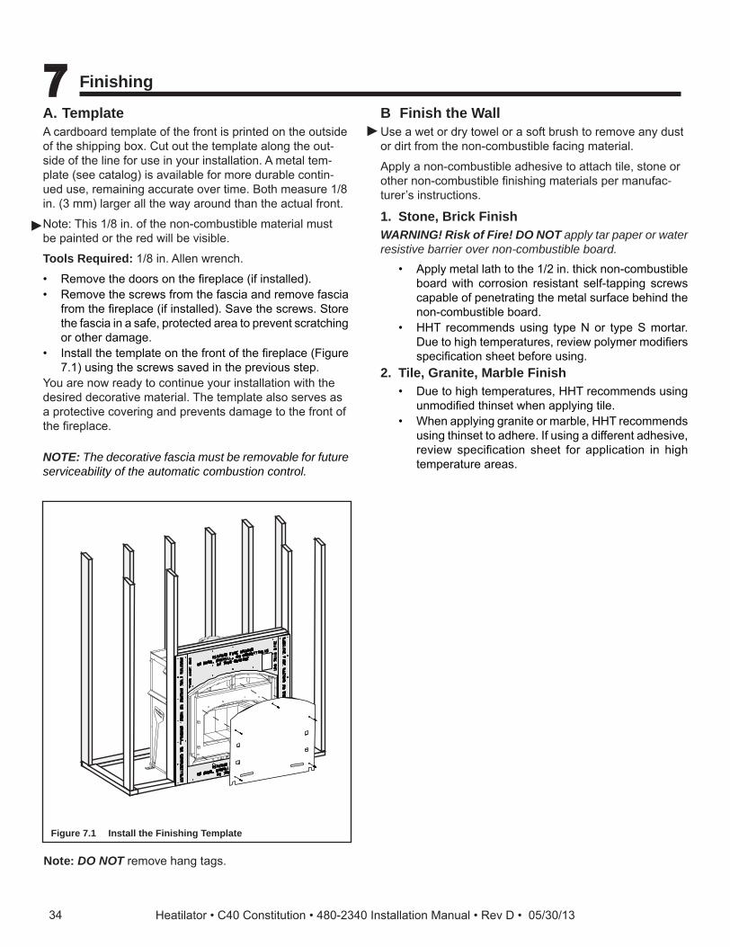
A. Template ar oar te late o t e ront is rinte on t e outsi e
o t e s i in o Cut out t e te late alon t e out-si e o t e line or use in our installation etal te -
late see atalo is availa le or ore ura le ontin-ue use re ainin a urate over ti e ot easure 1/8 in 3 lar er all t e a aroun t an t e a tual ront
ote is 1/8 in o t e non- o usti le aterial ust e ainte or t e re ill e visi le
Tools Required: 1/8 in llen ren
• Re ove t e oors on t e re la e i installe• Re ove t e s re s ro t e as ia an re ove as ia
ro t e re la e i installe ave t e s re s tore t e as ia in a sa e rote te area to revent s rat in or ot er a a e
• Install t e te late on t e ront o t e re la e i ure 1 usin t e s re s save in t e revious ste
ou are no rea to ontinue our installation it t e esire e orative aterial e te late also serves as
a rote tive overin an revents a a e to t e ront o t e re la e
NOTE: The decorative fascia must be removable for future serviceability of the automatic combustion control.
Figure 7.1 Install the Finishing Template
Note: DO NOT re ove an ta s
B Finish the Wallse a et or r to el or a so t rus to re ove an ust
or irt ro t e non- o usti le a in aterial
l a non- o usti le a esive to atta tile stone or ot er non- o usti le nis in aterials er anu a -turer s instru tions
1. Stone, Brick FinishWARNING! Risk of Fire! DO NOT apply tar paper or water resistive barrier over non-combustible board.
• l etal lat to t e 1/2 in t i non- o usti le oar it orrosion resistant sel -ta in s re s a a le o enetratin t e etal sur a e e in t e
non- o usti le oar• HH re o en s usin t e or t e ortar
Due to i te eratures revie ol er o i ers s e i ation s eet e ore usin
2. Tile, Granite, Marble Finish• Due to i te eratures HH re o en s usin
un o i e t inset en a l in tile• en a l in ranite or ar le HH re o en s
usin t inset to a ere I usin a i erent a esive revie s e i ation s eet or a li ation in i te erature areas
34 Heatilator • C40 Constitution • 480-2340 Installation Manual • Rev D • 05/30/13
►
►

C. Mantel and Wall Projections o usti le antel a e ositione no lo er t an 0
in 1524 ro t e ase o t e re la e
Re er to e tion 3 or re u e antel ei t allo an es
e o usti le antel a ave a a i u e t o 12 in 305 Co usti le tri ie es t at ro e t no
ore t an 3/4 in 1 ro t e a e o t e re la e an e la e no loser t an in 152 ro t e to
or si e o t e e orative ront Co usti le tri ust not over
• t e etal sur a es o t e re la e• ere t e non- o usti le oar is la e over t e
etal sur a es• t e s a e et een t e etal a e o t e re la e an
ra in e ers
60 in.( 1 5 24 m m )
M a nt e l
C l e a r a nc e s a r e f r o m b o t t o m o f a p p l ia nc e t o l o w e r e d g e o f m a nt e l o r t r im
T r im
48 in.( 1 21 9 m m )
Figure 7.2 Mantel Specifications
D. Finishing the Hearth Extension
Table 7.1
R = 1/k x inches of thickness
Table 7.2
WARNING! Risk of Fire! High temperatures, sparks, em-bers or other burning material falling from the fireplacemayigniteflooringorconcealedcombustiblesurfaces.• ProtectivemetalhearthstripsMUSTbeinstalled.• Hearth extensions MUST be installed exactly as
specified.
eart e tension ust e installe it all re la es to rote t t e o usti le oor in ront o t e re la e ro ot ra iant eat an s ar s
• ou M use a eart e tension it t is re la e
• Re er to i ure 4 or ini u i ensions• is re la e as een teste an a rove or use it
a eart e tension insulate to a ini u R value o 2 0
• e eart e tension aterial M e overe it tile stone or ot er non- o usti le aterial
• Manu a ture eart aterials ill usuall ave a u lis e R value resistan e to eat or k value on u tivit o eat Re er to t e or ula in a le 1
to onvert a value to an R value• Re er to a le 2 or eart e tension insulation
alternatives
Hearth Extension Insulation Alternatives, R Value = 2.06
Materialk per inch
thickr per inch
thick
Minimum thickness required
Heart Ho e H 3 H 4 0 4 2 0 1 in
Mi ore 300 0 4 2 0 1 in
Duro Ce ent oar 1 2 0 52 4 in
Ce ent Mortor 5 0 0 20 10 1/2 in
Co on ri 5 0 0 20 10 1/2 in
Cera i ile 12 50 0 08 25 3/4in
r stron riva uar lus 0 4 2 18 1 in
Mar le 14.3-20.0 0.07-0.05 29 1/2 - 41 1/4 in.
35Heatilator • C40 Constitution • 480-2340 Installation Manual • Rev D • 05/30/13

8 in. (203mm) minimum from each side offuel loading door
AB
Figure 7.3 Minimum Hearth Extension Dimensions
• ire la e an Heart tension us on t e oor on- o usti le oorin a ini u o 20 in 508
in ront o an 8 in 203 to eit er si e o t e uel o enin is re uire as s o n in i ure 3
e onstru tion o an aterials use or a eart e tension are s o n in i ure 4 eart e tension o t is onstru tion a e overe it an non-o usti le e orative aterial an a ave a ini u t i ness as er i ure 4 eal a s et een
t e eart e tension an t e ront o t e re la e it a ea o non- o usti le sealant or rout
F a s c iaO u t e r C a n F l a ng e
P r o t e c t iv e m e t a lh e a r t h s t r ip
T il e , m a r b l e o r o t h e r no n- c o m b u s t ib l e f inis h m a t e r ia l
M inim u m 4 in. ( 1 0 2 m m ) C e m e nt B o a r d o r e q u iv a l e nt , ( o r t w o p ie c e s H X 4)
M inim u m 20 in. ( 5 0 8 m m ) in f r o nt a nd 8 in. ( 20 3m m ) o n s id e s t o f u e l l o a d ing d o o r s
C o m b u s t ib l e F l o o r
. . . . . . . . . . . . . . . . . . . . . . . . . . . . . . . . . . . . . . . . . . . . . . . . . . . . . . . . . . . . . . . . . . . . . . . . . . . . . . . . .
. . .
. . .
. .
N o n- c o m b u s t ib l e m a t e r ia l s u p p l ie d w it h u nit .
. . .
. . .
. . .
. .
N o n- c o m b u s t ib l e s e a l a nt o r g r o u tT il e , m a r b l e o r o t h e r no n- c o m b u s t ib l e f inis h m a t e r ia l
Figure 7.4 Fireplace and Hearth Extension Flush on the Floor.
• Raise Heart tension ra in e eart ra in ust e onstru te o non-
o usti le aterials su as etal ra in or e uivalent aterial an to e it t o H 4s or e uivalent aterial a le 2
When creating the platform, allow for the thickness of the non-combustible finishing materials i ure 5
O u t e r C a n F l a ng e
N o n- c o m b u s t ib l e m a t e r ia l s u p p l ie d w it h u nit
F a s c ia
P r o t e c t iv e m e t a lh e a r t h s t r ip
M inim u m 4 in. ( 1 0 2 m m ) C e m e nt B o a r d o r e q u iv a l e nt , ( o r t w o p ie c e s H X 4)
M inim u m 20 in. ( 5 0 8 m m ) in f r o nt a nd 8 in. ( 20 3 m m ) o n s id e s t o f u e l l o a d ing d o o r s
C o m b u s t ib l e F l o o r
N o n- c o m b u s t ib l e s e a l a nt o r g r o u tT il e , m a r b l e o r o t h e r no n- c o m b u s t ib l e f inis h m a t e r ia l. . . . . . . . . . . . . . . . . . . . . . . . . . . . . . . . . . . . . . .. . . . . . . . . . . . . . . . . . . . . . . . . . . . . . . . . . . . . . .
. . .
. . .
. . .
. .
. . .
. . .
. . .
. .
N o n- c o m b u s t ib l ef r a m ing m a t e r ia l s
Figure 7.5 Raised Hearth Extension to Bottom of Fascia
• ire la e installe us on t e oor an eart e tension raise to otto o as ia
on- o usti le oorin a ini u o 20 in 508 in ront o an 8 in 203 to eit er si e o t e uel o enin is re uire see i ure 3
WARNING! Risk of Fire!
Hearth extensions are to be installed only as illustrated to prevent high tempertures from occurring on concealed combustible materials.
Model # A B
C40in. 41 20
mm 1041 508
3 Heatilator • C40 Constitution • 480-2340 Installation Manual • Rev D • 05/30/13

WARNING! Risk of Fire! • Maintainclearances. • Useonlynon-combustiblematerialbelowstandoffs,
material such as cement board is acceptable. • Framingorfinishingmaterialusedonthefrontof
thefireplacecloserthantheminimumslisted,mustbe constructed entirely of non-combustible materi-als (i.e., steel studs, concrete board, etc.).
WARNING! Risk of Fire! Hearth & Home Technologies is not responsible for
discoloration, cracking or other material failures of finishingmaterialsduetoheatexposureorsmoke.
• Choosefinishingmaterialscarefully.
S e a l ins id e p e r im e t e r o f f ir e p l a c e f inis h e d o p e ning w it h no n- c o m b u s t ib l e g r o u t t o p r e v e nt r is k o f f ir e a nd c o l d a ir inf il t r a t io n.
7 10 0
45 - 1/4 in .( 115 0 m m )
47 - 1/2 in .( 12 0 7 m m )
N O N - C O M B U S T I B L E Z O N E
Figure 7.6
E. Non-Combustible Sealant Material• ter o letin t e installation o non- o usti le
aterial in t e re uire non- o usti le one an t e non- o usti le nis in aterial over t at re ove t e te late
• ea o non- o usti le sealant or u er Calsti ust e use to lose o an a s at t e to an si es et een t e ire la e an non- o usti le a in i ure to revent ol air lea s an t e ris o re
ar e a s an e ri e it er lass ro e as et• en installation o t e e orative aterial is o lete
re la e/install t e as ia an re la e oors
3Heatilator • C40 Constitution • 480-2340 Installation Manual • Rev D • 05/30/13
►

8 Fireplace Setup
A. Firebrick Placemente re o o our re la e is line it i ualit re-
ri i as e e tional insulatin ro erties
Do not use a rate si l uil a re on t e re o oor
Do not o erate t e re la e it out ri s Ma e sure ri s are installe as s o n
IM R e ri s are ver si ilar in si e e ertain ou ave t e ro er ri in t e orre t lo ation Measure
t e ri si e or a ura ter t e oals are o letel oole re ove all ol
re ri an as ro re la e an va uu out re o
- Re ove ne ri set ro o an la out to ia ra as s o n in i ure 8 2.
- a otto ri s in re o- Install rear ri s on t e to o t e otto ri s
li e to o ri s un er li on a o re o all an us otto o ri a
- Install si e ri s li e to o ri un er li s on si e o re o an us t e otto o t e ri until it is us it t e si e o t e re o
Figure 8.1 Fire Brick Configurations
Figure 8.2 Fire Brick Configurations
Table 8.1
3
3
3
3
3
3
1 1
1 1 1
3 3
4 4
2 2
3
2
3
3 3
3
3
3 3
2
1
4
1 1 1
1
4
# Brick Size Qty. in Set1 13-1/4 4-1/2 1-1/4 52 13-1/2 4-1/2 1-1/4 / 1-1/2 a er 23 12 4-1/2 1-1/4 84 12-1/2 4-1/2 1-1/4 2
38 Heatilator • C40 Constitution • 480-2340 Installation Manual • Rev D • 05/30/13

B. Baffle and Blanket Placementnsure orre t a e an a e rote tion annel la e-ent re la e a e o onents i a a e or issin
e era i lan et an a e oar M e in onta t it t e a o t e re o an even it ea ot er in
the ront e a e rote tion annel M e in osi-tion
Figure 8.3
Cera ic Blan eta of ire o
Baffle Board
Baf le rote tion C annel in osition
3Heatilator • C40 Constitution • 480-2340 Installation Manual • Rev D • 05/30/13

9 Reference Materials
A. Chimney Componentse ollo in ra in s s o t e -300 eries i ne an re la e o onents i a e sa el use it t is
re la e
I D 4 I ns u l a t e d D u c t
U D 4 U nins u l a t e d D u c t
42 in. ( 1 0 67 m m )
4 in. ( 1 0 2 m m ) i.d .
42 in.( 1 0 67 m m )
4 in. ( 1 0 2 m m ) i.d .
8 in.( 20 3 m m )
1 0 - 1 /2 in.( 267 m m )
A
B
Catalog # DescriptionC 4 C i ne ir it
ID4/ID Insulate Du t/ utsi e ir
D4/ D ninsulate Du t/ utsi e ir
30 C i ne e tion - in 152 lon
312 C i ne e tion - 12 in 305 lon
318 C i ne e tion - 18 in 45 lon
324 C i ne e tion - 24 in 10 lon
33 C i ne e tion - 3 in 14 lon
348 C i ne e tion - 48 in 121 lon
3 C i ne ta ili er
315 C i ne set/Return - 15 e
330 C i ne set/Return - 30 e
338 Ceilin iresto - trai t
33 Ceilin iresto - 15 e
340 Ceilin iresto - 30 e
8 300 trai t tti Insulation iel 24 in 10
8 C i ne oint an
C 8 C i ne ra et
R 3 0 Roo las in - lat to /12 it
R 3 1 Roo las in - /12 to 12/12 it
D 134/14 to onal De orative Ca s
D 134/14 uare De orative Ca s
3 5 uare er ination Ca
C 3 5 erra Cotta er ination Ca
R344 Roun er ination Ca
R342 Roun eles o in er ination Ca
R- R o ent it
345 uare er ination Ca
345 uare er ination Ca - ainte
342 o ent Roun er ination Ca
C 35M C ase o sol in a o 10
12 Manu a ture Ho e i le
MH841 Manu a ture Ho e i le tension 20 in /508
H 4 Mi ore Heart tension 20 in /508 i e
D 33 De orative rou - 3 t 3 t 1 1
D 4 De orative rou - 4 t t 1 22 1 83
D - De orative rou - 2 in 2 in 0 0
iel Constru te rou s ee oo urnin er ination Ca
C -3 a ter - Ma e use it t e ollo in a s
C eries
D eries
1 0 - 1 /2 in.( 28 7 m m )
1 2 in.( 30 5 m m )
5 - 1 /4 in.( 1 33 m m ) 4 in. ( 1 0 2 m m )
1 2 in.( 30 5 m m )
CAK4A Chimney Air Kit
Catalog #A B
in mm in mm30 152 4-3/4 121
312 12 305 10-3/4 2 3
318 18 45 1 -3/4 425
324 24 10 22-3/4 5 8
33 3 14 34-3/4 883
348 48 121 4 -3/4 118
40 Heatilator • C40 Constitution • 480-2340 Installation Manual • Rev D • 05/30/13

RF370 - Roof Flashing Flat to 6/12 Pitch
RF371 - Roof Flashing 6/12 to 12/12 Pitch
Firestop Spacer
tual en t e tive len t len t o i ne art
a ter it as een sna e to anot er
A
B 1 4- 1 /2 in.( 368 m m )
24- 5 /8 in.( 625 m m )
27- 3/8 in.( 69 5 m m )
1 2 in.( 30 5 m m )
31 in.( 78 7 m m )
24- 5 /8 in.( 625 m m )
1 2 in.( 30 5 m m )
Catalog # A B338 0- e 14-1/2 in 3 8
33 15- e 18-3/8 in 4
340 30- e 23 in 584
20 - 3/4 in.( 5 27 m m )
I ns id eD ia m e t e r
8 in.( 20 3 m m )
O u t s id eD ia m e t e r1 0 - 1 /2 in.( 267 m m )
4- 3/4 in. ( 1 21 m m )E f f e c t iv e H e ig h t
SL3 Chimney Stabilizer
I ns id e D ia m e t e r8 in. ( 20 3 m m )
O u t s id e D ia m e t e r1 0 - 1 /2 in.( 267 m m )
SL315 Chimney Offset/Return - 15 deg.SL330 Chimney Offset/Return - 30 deg.
Assem b l edDiam eter: 14 1/2 in . /368 m m
H eig h t: 2 4 in . /610 m m
AS8 SL300 Straight Attic Insulation Shield
2 in. ( 5 1 m m )
1 0 - 1 /2 in.( 267 m m )
JB877 Chimney Joint Band
1 0 - 1 /2 in.( 267 m m )
CB876 Chimney Bracket
MH841 Manufactured Home Thimble Extension
24- 5 /8 in.( 625 m m )
1 6- 5 /8 in.( 422 m m )
29 in.( 737 m m )
1 6- 5 /8 in.( 422 m m )
12966A Manufactured Home Thimble
41Heatilator • C40 Constitution • 480-2340 Installation Manual • Rev D • 05/30/13

20 in.( 5 0 8 m m )
66 in.( 1 676 m m )
1 /2 in.( 1 3 m m )
HX4 Micore Hearth Extension
B
A
C
B
C
A
DTS134/DTS146 DTO134/DTO146Decorative Caps
DTO134 A B Cin 34 20 24m m 8 64 5 0 8 61 0
DTO146in 46 22.7 26m m 1 1 68 5 76 660
DTS134 A B Cin 34 21 .1 8 24m m 8 64 5 38 61 0
DTS146in 46 21 .1 8 26m m 1 1 68 5 38 660
23 in.( 5 8 4 m m )
1 9 in.( 48 3 m m )
1 5 - 5 /8 in.( 39 7 m m )
ST375 Square Termination Cap
22 1 /2 in.( 5 72 m m )
9 1 /2 in.( 241 m m )
1 6 1 /2 in.( 41 9 m m )
9 1 /2 in.( 241 m m )
TCT375 Terra Cotta Termination Cap
34- 3/4 in.( 8 8 3 m m )
32- 1 /2 in.( 8 26 m m )
TR342 Round Telescoping Termination Cap
1 5 - 3/4 in.( 40 0 m m )
TR344 Round Termination Cap
42 Heatilator • C40 Constitution • 480-2340 Installation Manual • Rev D • 05/30/13

72 in.( 1 8 29 m m )
36 in.( 9 1 4 m m )
2 in. ( 5 1 m m )
1 0 - 7/8 in.( 276 m m )
CT35M Chase Top
TR-TVK Top Vent Kit
1 3 1 /4 in.( 337 m m )
1 8 in. ( 45 7 m m )
1 6 1 /4 in.( 41 3 m m )
26 1 /2 in.( 673 m m )
28 5 /8 in.( 727 m m )
TS345 Square Termination CapTS345P Painted Square Termination Cap
32 in.( 8 1 3 m m )
34- 1 /4 in.( 8 70 m m )
TV342 Top Vent Round Termiantion Cap
A
B
C
D
Catalog #A B C D
in. mm in. mm in. mm in. mm
D 33 3 14 3 14 8 5 21 11 2
D 4 48 121 2 182 8 5 21 11 2
LDS33/LDS46 Decorative Shroud
Catalog # A B C E E
D -in. 2 12 5 15 5 22 23
mm 0 318 3 4 533 584
ED
A
CB
LDS-BV Decorative Shroud
26 in.
7 3/4 in.
CT-3A Adapter
43Heatilator • C40 Constitution • 480-2340 Installation Manual • Rev D • 05/30/13

Heatilator a ran o Heart Ho e e nolo ies5 1 215t treet est a eville M 55044
eatilator o
lease onta t our Heatilator ealer it an uestions or on ernsor t e lo ation o our nearest Heatilator ealer lease visit eatilator o
B. Accessories
MESH-HHT Firescreen
44 Heatilator • C40 Constitution • 480-2340 Installation Manual • Rev D • 05/30/13