Embed Size (px)
Citation preview
INSTALLATION MANUAL
FOR
ROCK KRAWLER SUSPENSION, INC.
JK MID ARM SYSTEMS
FIFTH EDITION
07/01/10

2
Dear customer: Thank you for purchasing the best system on the market for your Jeep Vehicle.
We are sure you will be happy with this system after your installation is complete. Please take
your time during the installation and be sure to do it correctly. Completely read the directions
before starting your installation so you know what to expect. Remember, your personal safety
depends on it. Should you have any questions during this installation feel free to give our tech
line a call (518-270-9822) and we will be happy to help you.
Warning
Read and understand all instructions, warnings and safety precautions in these
instructions and your owner’s manual before attempting to install these
components.
Caution
Proper installation of Rock Krawler Suspension, Inc. Products requires knowledge
of recommended procedures for disassembly/assembly of OE vehicles and
components. Access to OE shop manuals and special tools are required.
Attempting to install this kit without knowledge of these procedures may affect the
safety of your vehicle and or the performance of these components. Rock Krawler
Suspension, Inc. strongly recommends that this system be installed by a certified
mechanic with off road experience.
Warning
Rock Krawler Suspension, Inc. does not recommend combined use of suspension
Note: BE SURE TO CHECK ALL FASTENERS FOR PROPER TORQUE BEFORE TEST DRIVE. RECHECK AFTER 500 MILES AND BE SURE TO CHECK
PERIODICALLY.

3
lifts, body lifts or other lift devices. Combined use of lifts may result in unsafe and
unexpected handling characteristics. Also, many states now have laws restricting
Vehicle lift, bumper heights and other alterations. Consult local laws to determine
if your proposed alterations (including installation of this system) comply with
your state laws.
Caution
Rock Krawler Suspension Inc. recommends the use of locktite on all hardware,
unless noted otherwise.
Warning
Properly block and secure vehicle prior to installation.
Warning
Always wear safety glasses when using power tools
Warning
Rock Krawler Suspension Inc. does not condone or authorize the use of any other
suspension components with its products. Should Rock Krawler Systems or
components be installed in junction with other products or not per the provided
instructions Rock Krawler Suspension Inc.’s warranty is void and is not to be held
accountable for any resulting actions.
Warning
The use of limiting straps is recommended to avoid possible damage from over
extending the suspension of your vehicle.
4
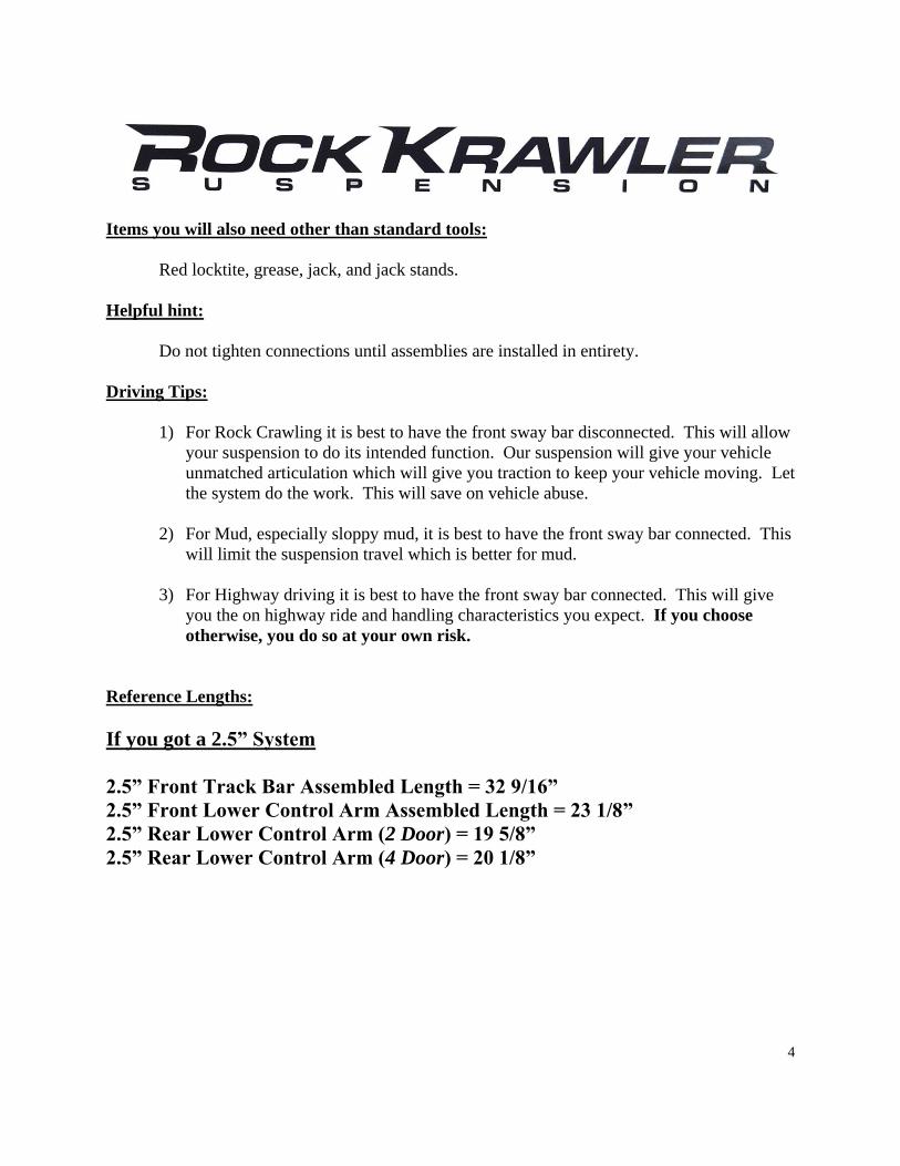
Items you will also need other than standard tools:
Red locktite, grease, jack, and jack stands.
Helpful hint:
Do not tighten connections until assemblies are installed in entirety.
Driving Tips:
1) For Rock Crawling it is best to have the front sway bar disconnected. This will allow
your suspension to do its intended function. Our suspension will give your vehicle
unmatched articulation which will give you traction to keep your vehicle moving. Let
the system do the work. This will save on vehicle abuse.
2) For Mud, especially sloppy mud, it is best to have the front sway bar connected. This
will limit the suspension travel which is better for mud.
3) For Highway driving it is best to have the front sway bar connected. This will give
you the on highway ride and handling characteristics you expect. If you choose
otherwise, you do so at your own risk.
Reference Lengths:
If you got a 2.5” System
2.5” Front Track Bar Assembled Length = 32 9/16”
2.5” Front Lower Control Arm Assembled Length = 23 1/8”
2.5” Rear Lower Control Arm (2 Door) = 19 5/8”
2.5” Rear Lower Control Arm (4 Door) = 20 1/8”
5
If you got a 3.5” System
3.5” Front Track Bar Assembled Length = 32.625”
3.5” Rear Track Bar Assembled Length = 39.75”
3.5” Front Lower Control Arm Assembled Length = 23.125”
3.5” Front Upper Control Arm Assembled Length = 19.375”
3.5” Flex System Rear Lower Control Arm (2 Door) = 19.50”
3.5” Flex System Rear Lower Control Arm (4 Door) = 20.00”
3.5” X or X+ System Rear Lower Control Arm (2 Door) = 21.00”
3.5” X or X+ System Rear Lower Control Arm (4 Door) = 21.375”
3.5” X System Rear Upper Control Arm (2 Door) = 19.50”
3.5” X System Rear Upper Control Arm (4 Door) = 18 15/16”
3.5” X+ System Rear Upper Control Arm (2 Door) = 19.375”
3.5” X+ System Rear Upper Control Arm (4 Door) = 18 15/16”
If you got a 5.5” System
5.5” Front Track Bar Assembled Length = 32.625”
5.5” Rear Track Bar Assembled Length = 40.00”
5.5” Front Lower Control Arm Assembled Length = 23.250”
5.5” Front Upper Control Arm Assembled Length = 19 9/16”
5.5” X or X+ System Rear Lower Control Arm (2 Door) = 21.00”
5.5” X or X+ System Rear Lower Control Arm (4 Door) = 21.50”
5.5” X System Rear Upper Control Arm (2 Door) = 19.625”
5.5” X System Rear Upper Control Arm (4 Door) = 19.00”
5.5” X+ System Rear Upper Control Arm (2 Door) = 19.50”
5.5” X+ System Rear Upper Control Arm (4 Door) = 18 15/16”
Please Note: All Control Arms, Torque Arms, Track Bars and Triangulated 4 -Link
Assemblies come pre-assembled, but they require final adjustment as specified in the
directions above.
6
Start with the Front End
1. Make sure vehicle is still on a level hard, working surface. Block the rear wheels so the vehicle cannot move and
make sure the emergency brake is applied. Raise the front of vehicle and support with safety jack stands. Locate
jack stands on the frame in front of the axle.
2. Remove the front rims and tires.
3. Support the front axle housing using a hydraulic floor jack.
4. Remove the front shocks. Keep the original hardware to install the new shocks.
5. Remove the front sway bar links.
6. Lower the front axle assembly.
7. Remove the front track bar from the vehicle and save the OEM hardware for reuse.
8. Remove the front springs.
9. For all Non-Entry Level Systems (Entry Level and Stock Mod - Skip This Step) remove the front lower
control arms and save the hardware for reuse.
10. For all X Factor and X Factor Plus Kits (Flex, Entry Level, Stock Mod and Max Travel Kits - Skip This
Step) remove the front upper control arms and save the OEM hardware for reuse. Please note the passenger side
front upper control arm bolt at the frame is next to impossible to get out without cutting it off, so we have provided
you with a new 12mm x 90mm bolt and nylok nut so do what you have to do to get it out.
11. For all X Factor and X Factor Plus Kits (Flex, Entry Level, Stock Mod and Max Travel Kits - Skip This
Step) install the supplied front upper control arms with the clevis bracket at the axle and the Krawler Joint at the
frame using the OEM hardware. For the passenger side connection at the frame use the supplied 12mm x 90mm
bolt and 12mm nylok nut. Set the front upper control arms to the specified length in the control arm table on page 4
or 5 for your given application. Do not allow more than ½” of threads to show past the jam nut for final
adjustment.
12. For all Non-Entry Level Systems (Entry Level and Stock Mod - Skip This Step). All other systems; install
the front lower control arms with Krawler Joint (Spherical Joint) at the axle mount and the Monster Bushing on the
OEM frame mounts. Use the OEM hardware for installation. Set the front lowers to the specified length in the
control arm table on page 4 or 5 for your given application. Do not allow more than 5/8” of threads to show past
the jam nut for final adjustment. Helpful Hit: Orient the Krawler Joint for maximum amount of movement, then
add red loctite and tighten down the jam nut on the joint prior to installing the arm since it is difficult to get at the
jam nut when it is in the vehicle. Remember it is a 1”-14 Jam nut so do not be afraid to over tighten it (In other
words put something behind it for God Sakes).
Also note: The bend in the arms is for improved ground clearance. See below for proper orientation.

7
13. For all 5.5” Systems (2.5 and 3.5” Systems omit this step); install the front track bar bracket. Grab the front
track bar bracket and secure it in position as shown below using the OEM lower track bar hardware. Then drill out
the other two holes in the OEM bracket through the supplied bracket with a ½” drill bit as shown below. Then,
finish securing the new bracket with the supplied ½” x 3” bolts, ½” washers, and ½” nylok nuts.
8
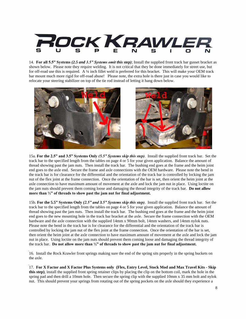
14. For all 5.5” Systems (2.5 and 3.5” Systems omit this step); Install the supplied front track bar gusset bracket as
shown below. Please note they require welding. It is not critical that they be done immediately for street use, but
for off-road use this is required. A ¼ inch fillet weld is preferred for this bracket. This will make your OEM track
bar mount much more rigid for off-road abuse! Please note, the extra hole is there just in case you would like to
relocate your steering stabilizer on top of the tie rod instead of letting it hang down below.
15a. For the 2.5” and 3.5” Systems Only (5.5” Systems skip this step). Install the supplied front track bar. Set the
track bar to the specified length from the tables on page 4 or 5 for your given application. Balance the amount of
thread showing past the jam nuts. Then install the track bar. The bushing end goes at the frame and the heim joint
end goes to the axle end. Secure the frame and axle connections with the OEM hardware. Please note the bend in
the track bar is for clearance for the differential and the orientation of the track bar is controlled by locking the jam
nut of the flex joint at the frame connection. Once the orientation of the bar is set, then orient the heim joint at the
axle connection to have maximum amount of movement at the axle and lock the jam nut in place. Using loctite on
the jam nuts should prevent them coming loose and damaging the thread integrity of the track bar. Do not allow
more than ½” of threads to show past the jam nut for final adjustment.
15b. For the 5.5” Systems Only (2.5” and 3.5” Systems skip this step). Install the supplied front track bar. Set the
track bar to the specified length from the tables on page 4 or 5 for your given application. Balance the amount of
thread showing past the jam nuts. Then install the track bar. The bushing end goes at the frame and the heim joint
end goes to the new mounting hole in the track bar bracket at the axle. Secure the frame connection with the OEM
hardware and the axle connection with the supplied 14mm x 90mm bolt, 14mm washers, and 14mm nylok nuts.
Please note the bend in the track bar is for clearance for the differential and the orientation of the track bar is
controlled by locking the jam nut of the flex joint at the frame connection. Once the orientation of the bar is set,
then orient the heim joint at the axle connection to have maximum amount of movement at the axle and lock the jam
nut in place. Using loctite on the jam nuts should prevent them coming loose and damaging the thread integrity of
the track bar. Do not allow more than ½” of threads to show past the jam nut for final adjustment.
16. Install the Rock Krawler front springs making sure the end of the spring sits properly in the spring buckets on
the axle.
17. For X Factor and X Factor Plus Systems only (Flex, Entry Level, Stock Mod and Max Travel Kits - Skip
this step), install the supplied front spring retainer clips by placing the clip on the bottom coil, mark the hole in the
spring pad and then drill a 10mm hole. Then secure the spring clip with the supplied 10mm x 35 mm bolt and nylok
nut. This should prevent your springs from rotating out of the spring pockets on the axle should they experience a
9
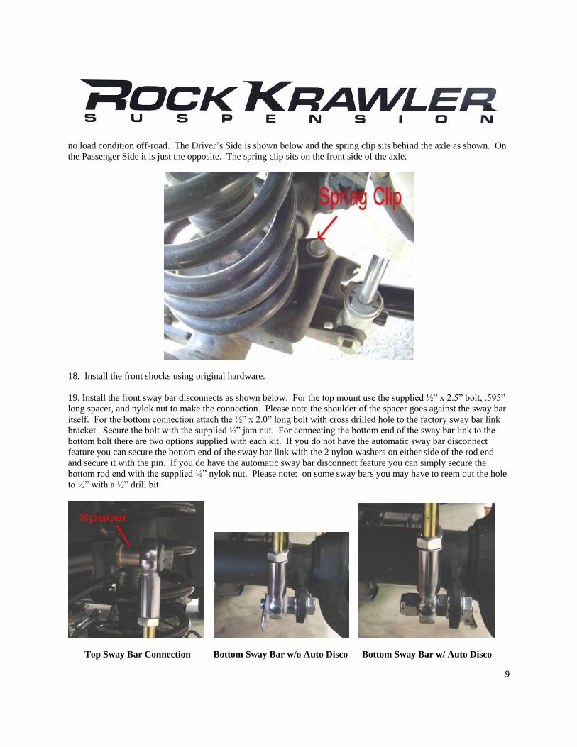
no load condition off-road. The Driver’s Side is shown below and the spring clip sits behind the axle as shown. On
the Passenger Side it is just the opposite. The spring clip sits on the front side of the axle.
18. Install the front shocks using original hardware.
19. Install the front sway bar disconnects as shown below. For the top mount use the supplied ½” x 2.5” bolt, .595”
long spacer, and nylok nut to make the connection. Please note the shoulder of the spacer goes against the sway bar
itself. For the bottom connection attach the ½” x 2.0” long bolt with cross drilled hole to the factory sway bar link
bracket. Secure the bolt with the supplied ½” jam nut. For connecting the bottom end of the sway bar link to the
bottom bolt there are two options supplied with each kit. If you do not have the automatic sway bar disconnect
feature you can secure the bottom end of the sway bar link with the 2 nylon washers on either side of the rod end
and secure it with the pin. If you do have the automatic sway bar disconnect feature you can simply secure the
bottom rod end with the supplied ½” nylok nut. Please note: on some sway bars you may have to reem out the hole
to ½” with a ½” drill bit.
Top Sway Bar Connection Bottom Sway Bar w/o Auto Disco Bottom Sway Bar w/ Auto Disco

10
20. For the 5.5” Systems Only (2.5” and 3.5” Systems skip this step). Disconnect the drag link from the OEM
pitman arm and the passenger side knuckle. Discard the OEM Drag Link since you will be installing the new H.D.
Rock Krawler Drag Link Assembly.
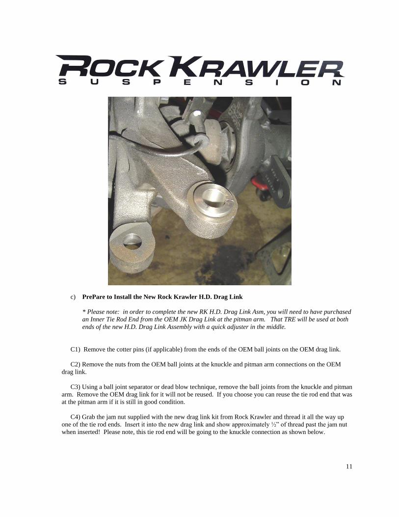
a) Drill out the passenger drag link knuckle mounting position to 7/8 of an inch as shown below.
b) Insert the split steel tapered sleeve into the knuckle as shown below. Please note for the drag link flip
the spacer goes on top of the knuckle. To go back to the OEM geometry simply put the spacer on the bottom as it
was before.
11
c) PrePare to Install the New Rock Krawler H.D. Drag Link
* Please note: in order to complete the new RK H.D. Drag Link Asm, you will need to have purchased
an Inner Tie Rod End from the OEM JK Drag Link at the pitman arm. That TRE will be used at both
ends of the new H.D. Drag Link Assembly with a quick adjuster in the middle.
C1) Remove the cotter pins (if applicable) from the ends of the OEM ball joints on the OEM drag link.
C2) Remove the nuts from the OEM ball joints at the knuckle and pitman arm connections on the OEM
drag link.
C3) Using a ball joint separator or dead blow technique, remove the ball joints from the knuckle and pitman
arm. Remove the OEM drag link for it will not be reused. If you choose you can reuse the tie rod end that was
at the pitman arm if it is still in good condition.
C4) Grab the jam nut supplied with the new drag link kit from Rock Krawler and thread it all the way up
one of the tie rod ends. Insert it into the new drag link and show approximately ½” of thread past the jam nut
when inserted! Please note, this tie rod end will be going to the knuckle connection as shown below.

12
P.S. Knuckle Connections
C5) Measure the OEM drag link operating length from center of ball joint to center of ball joint. Mark the
length for that is where you are going to start with your new assembly.
C6) Attach the quick adjuster to the newly supplied tie rod and thread it on all the way. Put the other OEM
tie rod end into the other end of the quick adjuster and thread it in all the way as well.
C7) Set the newly supplied drag link to the measured length of the original one by adjusting the quick
adjuster only. Do not adjust the other tie rod end that will be at the axle connection unless it is absolutely
necessary.
C8) Insert the ball joint ends of the tie rods into the knuckle connection and pitman arm connection in the
same orientation as the OEM units. Place the supplied 5/8 flat washer on top prior to threading on the nut.
C9) Torque the nuts down 90 to 100 ft-lbs.
C10) Be sure to do your best to center the steering wheel using the turn buckle style quick adjuster in the
drag link, then lock the jam nut using the wrench flat sections of the drag link for the tie rod end at the knuckle
and secure the quick adjuster by clamping down the slits on the quick adjuster as shown below. Be sure to
orient the tie rod ends so the ball joints are free to move without bind. Please note to follow the SAE rules of
thread engagement so you do not put yourself into a bad position!
13
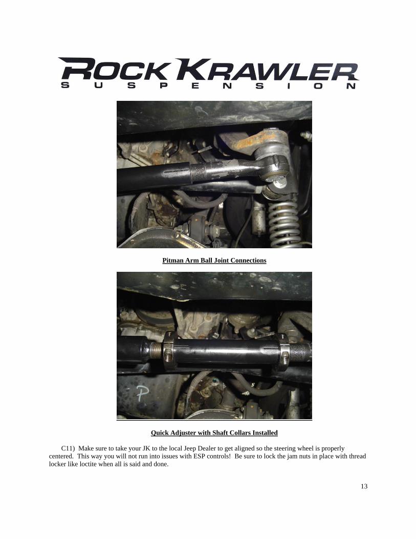
Pitman Arm Ball Joint Connections
Quick Adjuster with Shaft Collars Installed
C11) Make sure to take your JK to the local Jeep Dealer to get aligned so the steering wheel is properly
centered. This way you will not run into issues with ESP controls! Be sure to lock the jam nuts in place with thread
locker like loctite when all is said and done.

14
Please note: There is an extra hole in the front track bar bracket support bracket to allow for relocation of the
OEM steering stabilizer as shown below. All you need is a spacer and the hardware.
Steering Stabilizer Relocated
21. For all systems other than Entry Level (Entry Level and Stock Mod - Skip this step). Remove the factory
front rubber brake lines and install the new stainless steel brake lines. Do not worry about bleeding the brake system
at this time since you are going to have to install the new rear lines in a little while. Be sure to add slack to your
ABS lines and route them with your new stainless steel lines using two of the supplied zip ties to secure them
together.
22. Install front rims and tires and lower front of the vehicle to the ground, check that the front axle is centered
under the vehicle. If the axle is not centered, adjust rod end/krawler joints to center the axle. If the axle is centered,
tighten all hardware to proper torque spec. Do not allow more than ½” of threads to show past the jam nut for
final adjustment.
15
Now Lets Start the Rear Assembly
1. Park vehicle on a level, hard working surface. Raise rear of vehicle and support with safety jack stands. Locate
jack stands on the frame behind the rear axle.
2. Remove the rear rims and tires.
3. Support the rear axle using a hydraulic floor jack.
4. Remove the rear shocks and save the hardware for reuse.
5. Remove the rear sway bar links.
6. Lower the rear axle and remove the rear coil springs.
7. Remove the rear track bar and discard it, save the hardware for reuse.
8. For all systems other than Entry Level (Entry Level and Stock Mod Skip this step) remove the rear lower
control arms using and save the hardware for reuse.
9. For all X Factor and X Factor Plus Kits (Flex, Entry Level, Stock Mod and Max Travel Kits - Skip This
Step) remove the factory rear upper control arms and discard them, save the hardware for reuse.
10. Install the rear track bar relocation bracket as shown below. Attach the bracket using the OEM bolt with the
supplied 7/8” O.D. x 9/16 I.D. x 1.625” Long crush sleeve on the inside of the OEM lower track bar mount as shown
below. Drill a ½” hole through the inside of the factory bracket where the supplied hole in our bracket is and secure
that position with the supplied ½” x 1.25” long bolt, washers and nylok nut. Drill a second 10mm hole through the
top of the OEM bracket where the existing hole is in out new bracket and secure it with the supplied 10mmx35mm
bolt and 10mm nylok nut. Please note: Our bracket wings cup the OEM rear axle tubes. This is due to the
fact that the OEM factory rear track bracket is so weak. It is required before your first off-road adventure
with your JK that these wings be welded to the axle tubes. This will prevent any failures of the rear track
bracket assembly.
16
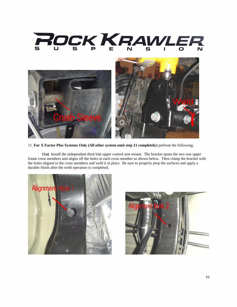
11. For X Factor Plus Systems Only (All other system omit step 11 completely) perform the following;
11a) Install the independent third link upper control arm mount. The bracket spans the two rear upper
frame cross members and aligns off the holes in each cross member as shown below. Then clamp the bracket with
the holes aligned to the cross members and weld it in place. Be sure to properly prep the surfaces and apply a
durable finish after the weld operation is completed.
17
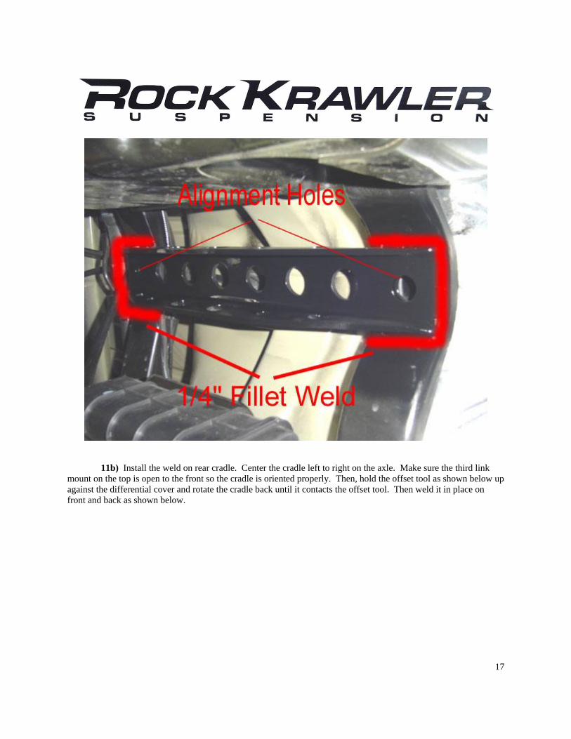
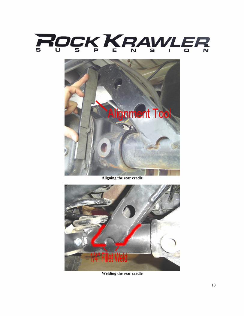
11b) Install the weld on rear cradle. Center the cradle left to right on the axle. Make sure the third link
mount on the top is open to the front so the cradle is oriented properly. Then, hold the offset tool as shown below up
against the differential cover and rotate the cradle back until it contacts the offset tool. Then weld it in place on
front and back as shown below.
18
Aligning the rear cradle
Welding the rear cradle
19
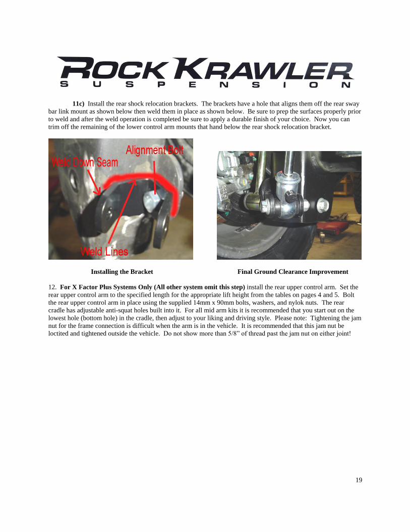
11c) Install the rear shock relocation brackets. The brackets have a hole that aligns them off the rear sway
bar link mount as shown below then weld them in place as shown below. Be sure to prep the surfaces properly prior
to weld and after the weld operation is completed be sure to apply a durable finish of your choice. Now you can
trim off the remaining of the lower control arm mounts that hand below the rear shock relocation bracket.
Installing the Bracket Final Ground Clearance Improvement
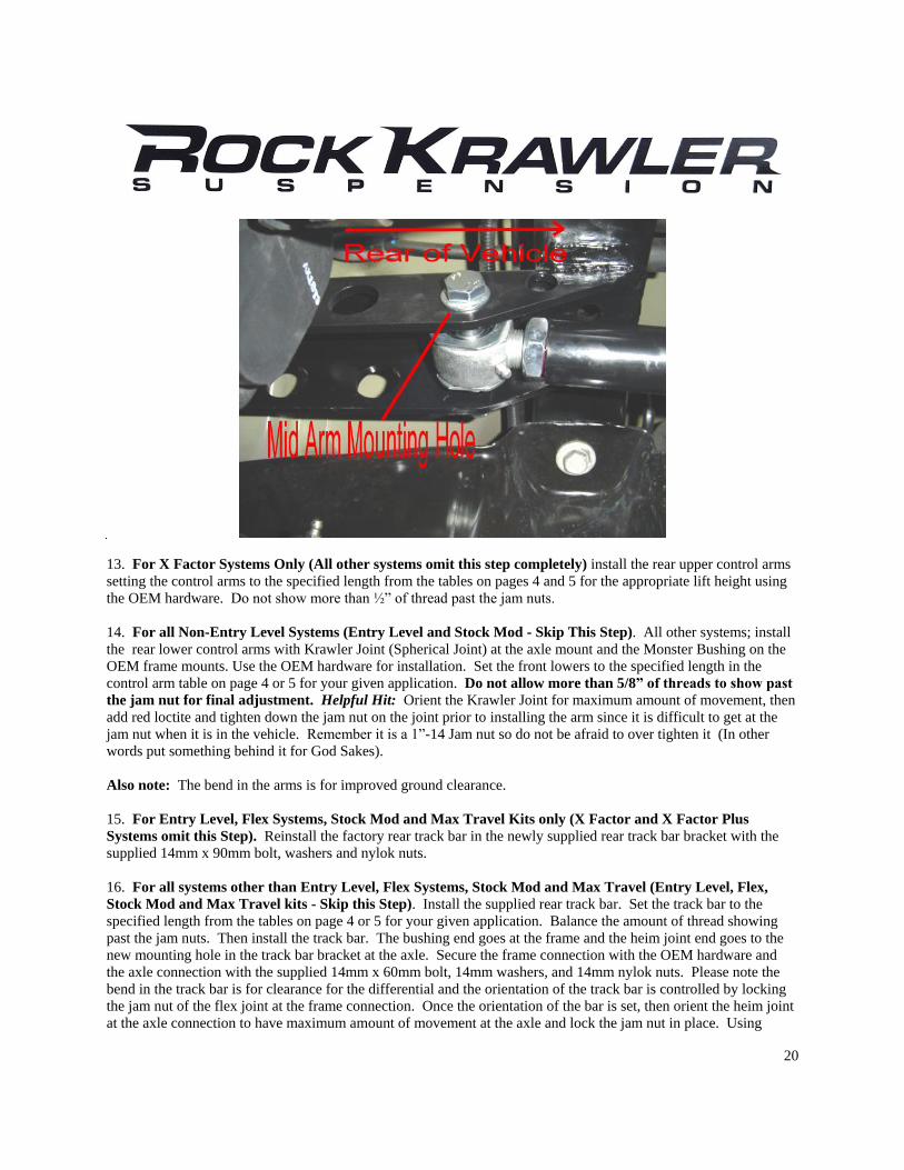
12. For X Factor Plus Systems Only (All other system omit this step) install the rear upper control arm. Set the
rear upper control arm to the specified length for the appropriate lift height from the tables on pages 4 and 5. Bolt
the rear upper control arm in place using the supplied 14mm x 90mm bolts, washers, and nylok nuts. The rear
cradle has adjustable anti-squat holes built into it. For all mid arm kits it is recommended that you start out on the
lowest hole (bottom hole) in the cradle, then adjust to your liking and driving style. Please note: Tightening the jam
nut for the frame connection is difficult when the arm is in the vehicle. It is recommended that this jam nut be
loctited and tightened outside the vehicle. Do not show more than 5/8” of thread past the jam nut on either joint!
20
13. For X Factor Systems Only (All other systems omit this step completely) install the rear upper control arms
setting the control arms to the specified length from the tables on pages 4 and 5 for the appropriate lift height using
the OEM hardware. Do not show more than ½” of thread past the jam nuts.
14. For all Non-Entry Level Systems (Entry Level and Stock Mod - Skip This Step). All other systems; install
the rear lower control arms with Krawler Joint (Spherical Joint) at the axle mount and the Monster Bushing on the
OEM frame mounts. Use the OEM hardware for installation. Set the front lowers to the specified length in the
control arm table on page 4 or 5 for your given application. Do not allow more than 5/8” of threads to show past
the jam nut for final adjustment. Helpful Hit: Orient the Krawler Joint for maximum amount of movement, then
add red loctite and tighten down the jam nut on the joint prior to installing the arm since it is difficult to get at the
jam nut when it is in the vehicle. Remember it is a 1”-14 Jam nut so do not be afraid to over tighten it (In other
words put something behind it for God Sakes).
Also note: The bend in the arms is for improved ground clearance.
15. For Entry Level, Flex Systems, Stock Mod and Max Travel Kits only (X Factor and X Factor Plus
Systems omit this Step). Reinstall the factory rear track bar in the newly supplied rear track bar bracket with the
supplied 14mm x 90mm bolt, washers and nylok nuts.
16. For all systems other than Entry Level, Flex Systems, Stock Mod and Max Travel (Entry Level, Flex,
Stock Mod and Max Travel kits - Skip this Step). Install the supplied rear track bar. Set the track bar to the
specified length from the tables on page 4 or 5 for your given application. Balance the amount of thread showing
past the jam nuts. Then install the track bar. The bushing end goes at the frame and the heim joint end goes to the
new mounting hole in the track bar bracket at the axle. Secure the frame connection with the OEM hardware and
the axle connection with the supplied 14mm x 60mm bolt, 14mm washers, and 14mm nylok nuts. Please note the
bend in the track bar is for clearance for the differential and the orientation of the track bar is controlled by locking
the jam nut of the flex joint at the frame connection. Once the orientation of the bar is set, then orient the heim joint
at the axle connection to have maximum amount of movement at the axle and lock the jam nut in place. Using
21
loctite on the jam nuts should prevent them coming loose and damaging the thread integrity of the track bar. Do not
allow more than ½” of threads to show past the jam nut for final adjustment.
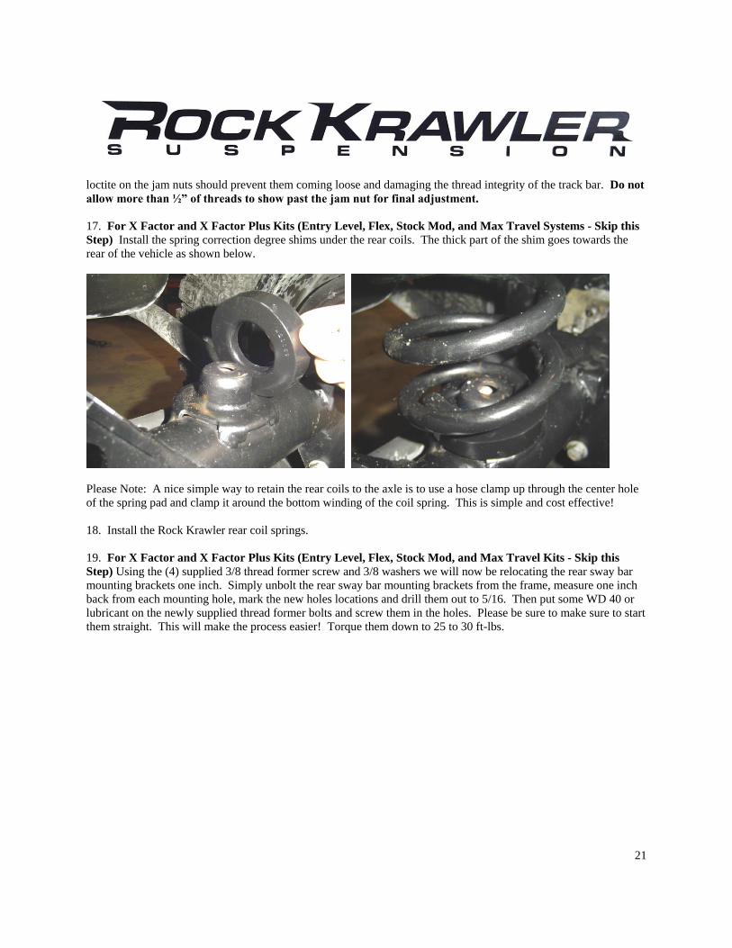
17. For X Factor and X Factor Plus Kits (Entry Level, Flex, Stock Mod, and Max Travel Systems - Skip this
Step) Install the spring correction degree shims under the rear coils. The thick part of the shim goes towards the
rear of the vehicle as shown below.
Please Note: A nice simple way to retain the rear coils to the axle is to use a hose clamp up through the center hole
of the spring pad and clamp it around the bottom winding of the coil spring. This is simple and cost effective!
18. Install the Rock Krawler rear coil springs.
19. For X Factor and X Factor Plus Kits (Entry Level, Flex, Stock Mod, and Max Travel Kits - Skip this
Step) Using the (4) supplied 3/8 thread former screw and 3/8 washers we will now be relocating the rear sway bar
mounting brackets one inch. Simply unbolt the rear sway bar mounting brackets from the frame, measure one inch
back from each mounting hole, mark the new holes locations and drill them out to 5/16. Then put some WD 40 or
lubricant on the newly supplied thread former bolts and screw them in the holes. Please be sure to make sure to start
them straight. This will make the process easier! Torque them down to 25 to 30 ft-lbs.
22
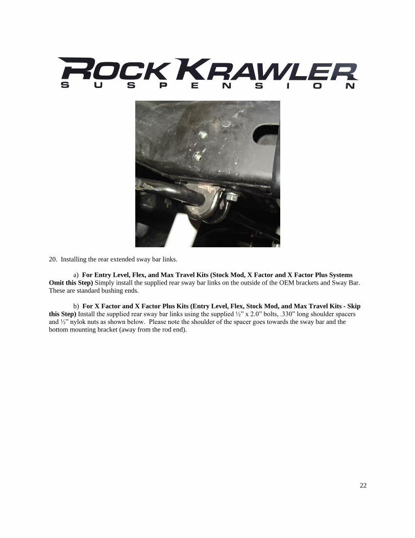
20. Installing the rear extended sway bar links.
a) For Entry Level, Flex, and Max Travel Kits (Stock Mod, X Factor and X Factor Plus Systems
Omit this Step) Simply install the supplied rear sway bar links on the outside of the OEM brackets and Sway Bar.
These are standard bushing ends.
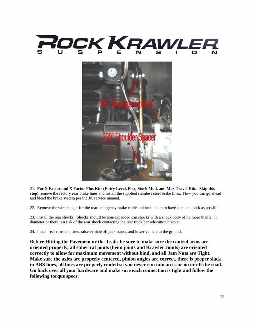
b) For X Factor and X Factor Plus Kits (Entry Level, Flex, Stock Mod, and Max Travel Kits - Skip
this Step) Install the supplied rear sway bar links using the supplied ½” x 2.0” bolts, .330” long shoulder spacers
and ½” nylok nuts as shown below. Please note the shoulder of the spacer goes towards the sway bar and the
bottom mounting bracket (away from the rod end).
23
21. For X Factor and X Factor Plus Kits (Entry Level, Flex, Stock Mod, and Max Travel Kits - Skip this
step) remove the factory rear brake lines and install the supplied stainless steel brake lines. Now you can go ahead
and blead the brake system per the JK service manual.
22. Remove the wire hanger for the rear emergency brake cable and route them to have as much slack as possible.
23. Install the rear shocks. Shocks should be non-expanded can shocks with a shock body of no more than 2” in
diameter or there is a risk of the rear shock contacting the rear track bar relocation bracket.
24. Install rear rims and tires, raise vehicle off jack stands and lower vehicle to the ground.
Before Hitting the Pavement or the Trails be sure to make sure the control arms are
oriented properly, all spherical joints (heim joints and Krawler Joints) are oriented
correctly to allow for maximum movement without bind, and all Jam Nuts are Tight.
Make sure the axles are properly centered, pinion angles are correct, there is proper slack
in ABS lines, all lines are properly routed so you never run into an issue on or off the road.
Go back over all your hardware and make sure each connection is tight and follow the
following torque specs;
24
Torque all 14mm and 9/16 bolts to 90-100 ft-lbs. Torque all 12mm and ½ bolts to 75-80 ft-
lbs. Torque all 10mm and 3/8 bolts to 30-35 ft-lbs.
Please note: If your steering wheel is off at all the ESP will be activated. This will be
corrected once the vehicle is aligned by a certified Jeep dealership.
A note about jam nuts and the consumer's responsibility. The installer is the person or
persons initially responsible for the proper setup of the suspension system and/or
components and the initial tightening of the jam nuts. The consumer or vehicle owner is the
person or persons responsible for maintaining the jam nuts tight. Failure to do so will
result in the rapid deterioration of the threads in the control arm and will impose a "cause
for concern" for the occupants of the vehicle. Failure to comply with the warnings headed
in the directions regarding the amount of threads showing past the jam nut will also cause
the same "cause for concern" for the occupants of the vehicle. All of the above items are
the responsibility of the vehicle owner and or installer. If a threaded section of a component
is bad it will show itself defective immediately. Threads that fail over time are due to
improper maintenance of jam nuts and can be proven very easily. Thread sections not
properly maintained or setup are not covered under warranty. This is the end user and
installer's responsibility.
Servicing of the Rock Krawler Rebuild able Joints is unique from the rest of the industry.
We supply our joints with a plug or socket head cap screw in them. Simply remove the
plug and put in some 3 in 1 oil which is preferred or WD-40 the reinstall the plug. We do
this for many reasons. The first is our joints are extremely tight and will not take grease
very easily. Second, in the off-road environment grease attracts much more dirt and debris
than it is worth causing joints to wear quickly. Grease would take forever to lubricate our
joints since they are so tight. 3 in 1 or WD-40 is clean, simple and lubricates quickly. If
worse comes to worse, simply spray down the outside of our joints liberally with WD-40 or
MPL and call it a day.
It is a requirement that your vehicle be taken to a Jeep Dealership for an
alignment. The Jeep Dealer should align the vehicle and also verify all
ESP/ABS connections are in good working order or trouble may arise. The
routing of ABS/ESP and Brake Lines is your responsibility. Do so carefully.
Good Job. Your installation is complete. Now go out and enjoy your vehicle.