Embed Size (px)
Citation preview
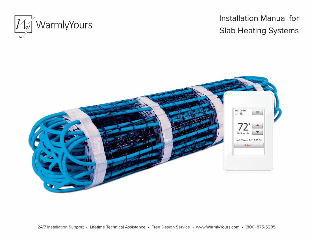
Installation Manual for
Slab Heating Systems
24/7 Installation Support • Lifetime Technical Assistance • Free Design Service • www.WarmlyYours.com • (800) 875-5285
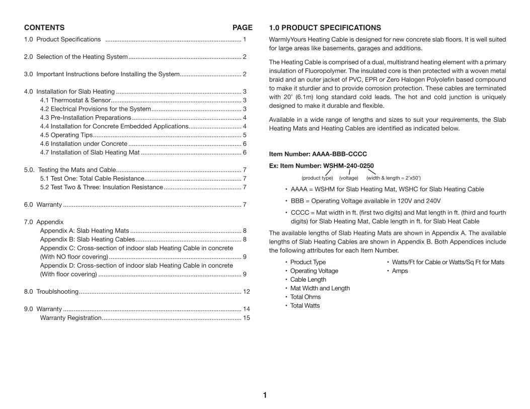
CONTENTS PAGE1.0 Product Specifications ............................................................................. 1
2.0 Selection of the Heating System ................................................................ 2
3.0 Important Instructions before Installing the System................................... 2
4.0 Installation for Slab Heating ....................................................................... 3 4.1 Thermostat & Sensor.......................................................................... 3 4.2 Electrical Provisions for the System ................................................... 3 4.3 Pre-Installation Preparations .............................................................. 4 4.4 Installation for Concrete Embedded Applications .............................. 4 4.5 Operating Tips .................................................................................... 5 4.6 Installation under Concrete ................................................................ 6 4.7 Installation of Slab Heating Mat ......................................................... 6
5.0. Testing the Mats and Cable ....................................................................... 7 5.1 Test One: Total Cable Resistance ....................................................... 7 5.2 Test Two & Three: Insulation Resistance ............................................ 7
6.0 Warranty ..................................................................................................... 7
7.0 Appendix Appendix A: Slab Heating Mats ............................................................... 8 Appendix B: Slab Heating Cables ............................................................ 8 Appendix C: Cross-section of indoor slab Heating Cable in concrete
(With NO floor covering) ........................................................................... 9 Appendix D: Cross-section of indoor slab Heating Cable in concrete
(With floor covering) ................................................................................. 9
8.0 Troublshooting ............................................................................................ 12
9.0 Warranty ..................................................................................................... 14 Warranty Registration ............................................................................... 15
1.0 PRODUCT SPECIFICATIONSWarmlyYours Heating Cable is designed for new concrete slab floors. It is well suited for large areas like basements, garages and additions.
The Heating Cable is comprised of a dual, multistrand heating element with a primary insulation of Fluoropolymer. The insulated core is then protected with a woven metal braid and an outer jacket of PVC, EPR or Zero Halogen Polyolefin based compound to make it sturdier and to provide corrosion protection. These cables are terminated with 20’ (6.1m) long standard cold leads. The hot and cold junction is uniquely designed to make it durable and flexible.
Available in a wide range of lengths and sizes to suit your requirements, the Slab Heating Mats and Heating Cables are identified as indicated below.
Item Number: AAAA-BBB-CCCC
Ex: Item Number: WSHM-240-0250
(product type) (voltage) (width & length = 2’x50’)
• AAAA = WSHM for Slab Heating Mat, WSHC for Slab Heating Cable
• BBB = Operating Voltage available in 120V and 240V
• CCCC = Mat width in ft. (first two digits) and Mat length in ft. (third and fourth digits) for Slab Heating Mat, Cable length in ft. for Slab Heat Cable
The available lengths of Slab Heating Mats are shown in Appendix A. The available lengths of Slab Heating Cables are shown in Appendix B. Both Appendices include the following attributes for each Item Number.
• Product Type • Watts/Ft for Cable or Watts/Sq Ft for Mats • Operating Voltage • Amps • Cable Length • Mat Width and Length • Total Ohms • Total Watts
1
2.0 SELECTION OF THE HEATING SYSTEMSelection of your Heating System will depend on the application. The following can be taken as a general guide:
INSTALL CHART
Application Watts per Sq.Ft. (per Sq.M.) - Cable spacing inches (mm)
Multiplier at given spacing
Indoor Slab Heating20 W/ft2 (161 to 215 W/m2) Recommended spacing 3” to 3.5” (76 to 89mm).
4 at 3” (76mm) 3.5 at 3.5” (89mm) 3 at 4” (102mm) 2.4 at 5” (127mm)
Formula: Area of Application x Multiplier at given cable spacing = Heated Cable Length requiredExample 1 (English): 100 sq.ft of Slab Heating x 4.0 at 3” spacing = 400 feet of Heated Cable requiredExample 2 (Metric): 9.3 sq.m of Slab Heating x 4.0 at 76mm spacing = 122m of Heated Cable required
Note: For normal plain bare slabs, stained or stamped use 3” spacing. For application when the slab also has a floor covering like tile or wood, use 5” spacing for a maximum of 15w/sq ft. to meet code requirements.
Please note the above-indicated values are meant as a general guide. Your values may vary depending on a number of factors. Please consult your Account Manager for assistance.
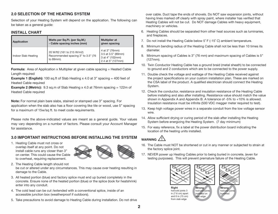
3.0 IMPORTANT INSTRUCTIONS BEFORE INSTALLING THE SYSTEM1. Heating Cable must not cross or
overlap itself at any point. Do not install cable runs any closer than 3” on center. This could cause the Cable to overheat, requiring replacement.
2. The Heating Cable length should not be cut or altered under any circumstances. This may cause over heating resulting in damage to the Cable.
3. All heated portion (blue) and factory splice must end up buried completely in the concrete. Ensure none of the heated portion (blue) or the splice (look for heatshrink) enter into any conduit.
4. The cold lead can be cut /extended with a conventional splice, inside of an accessible junction box (weatherproof if outdoors).
5. Take precautions to avoid damage to Heating Cable during installation. Do not drive
over cable. Duct tape the ends of shovels. Do NOT saw expansion joints, without having lines marked off clearly with spray paint, where installer has verified that Heating Cables will not be cut. Do NOT damage Cables with heavy equipment, machinery or vehicles.
6. Heating Cables should be separated from other heat sources such as luminaries, and fireplaces.
7. Do not install the Heating Cable below 5˚ F (-15˚ C) ambient temperature.8. Minimum bending radius of the Heating Cable shall not be less than 10 times its
diameter. 9. Minimum spacing of Cables is 3” (76 mm) and maximum spacing of Cables is 5”
(127mm).10. Twin Conductor Heating Cable has a ground braid (metal sheath) to be connected
to ground and 2 conductors which are to be connected to the power supply.11. Double check the voltage and wattage of the Heating Cable received against
the project specifications on your custom installation plan. These are marked on the CSA label of the product. A qualified electrician should connect the Heating System.
12. Check the conductor, resistance and insulation resistance of the Heating Cable before installing and also after installing. Resistance value should match the value shown in Appendix A and Appendix B. A tolerance of -5% to +10% is allowed. Insulation resistance must be infinite (500 VDC megger meter required to test).
13. Keep high voltage power wires in a separate conduit from the low voltage sensor wire.
14. Allow sufficient drying or curing period of the slab after installing the Heating System before energizing the Heating System. (7 day minimum)
15. For easy reference, fix a label at the power distribution board indicating the location of the heating units installed.
WARNING 16. The Cable must NOT be shortened or cut in any manner or subjected to strain at
the factory splice joint.17. NEVER power up Heating Cables prior to being buried in concrete, (even for
testing purposes). This will prevent premature failure of the Heating Cable.
2
2.5” in (6.3cm) maximumthickness brick or concrete paver
1.5” sand, stone dust or mortar
Plastic tie wrap
4 in (10) or 6 in (15) square 10 gauge wire mesh
Level of heating cable
2” (5 cm)
3” (7.6 cm)
8”-12” crushed rock aggregate
Righthot/cold joints 3 in (7.6 cm) apart and 6 in (15 cm) from slab edge
Wronghot/cold joints installed on slab edge
Wronghot/cold joints bunched
concrete wall
Junction box mounted on inside wall
Control jointConcrete
Heating cable secured to rebar with plastic tie wraps
Steel bar
3”
3”
Cable identification tag(within 3 in (7.5cm) of NPT connector)Cold lead
Conduit
Expansion joint
Heated Slab
ConduitHot/Cold
jointHeating
cable
Cold leads protected with 1-1/2in (3.8cm)minimum nonmetallic conduitwhere they emerge from slab
Topping 2 in (5.0 cm)minimum, to 3 in (7.5 cm)
maximum thickness
Dimension B must not exceed 6 in (15 cm)
Dimension A must not exceed 3 in (7.5 cm)
If dimension C exceeds 3 in(10 cm) an additional run of cable must be used
Pavers - No lip overhang
B
Splice
Lip edge rounded off to prevent cable damage
1.2 in (1.3 cm) wide steel prepunched strapping
Wrongcold joints
unche
Wrongcold joints
stalleslab
Cable must be at least 4 in (10 cm) from rail post
Cable must be at least 4 in (10 cm) from edge
C
A
4.0 INSTALLATION FOR INDOOR SLAB HEATING
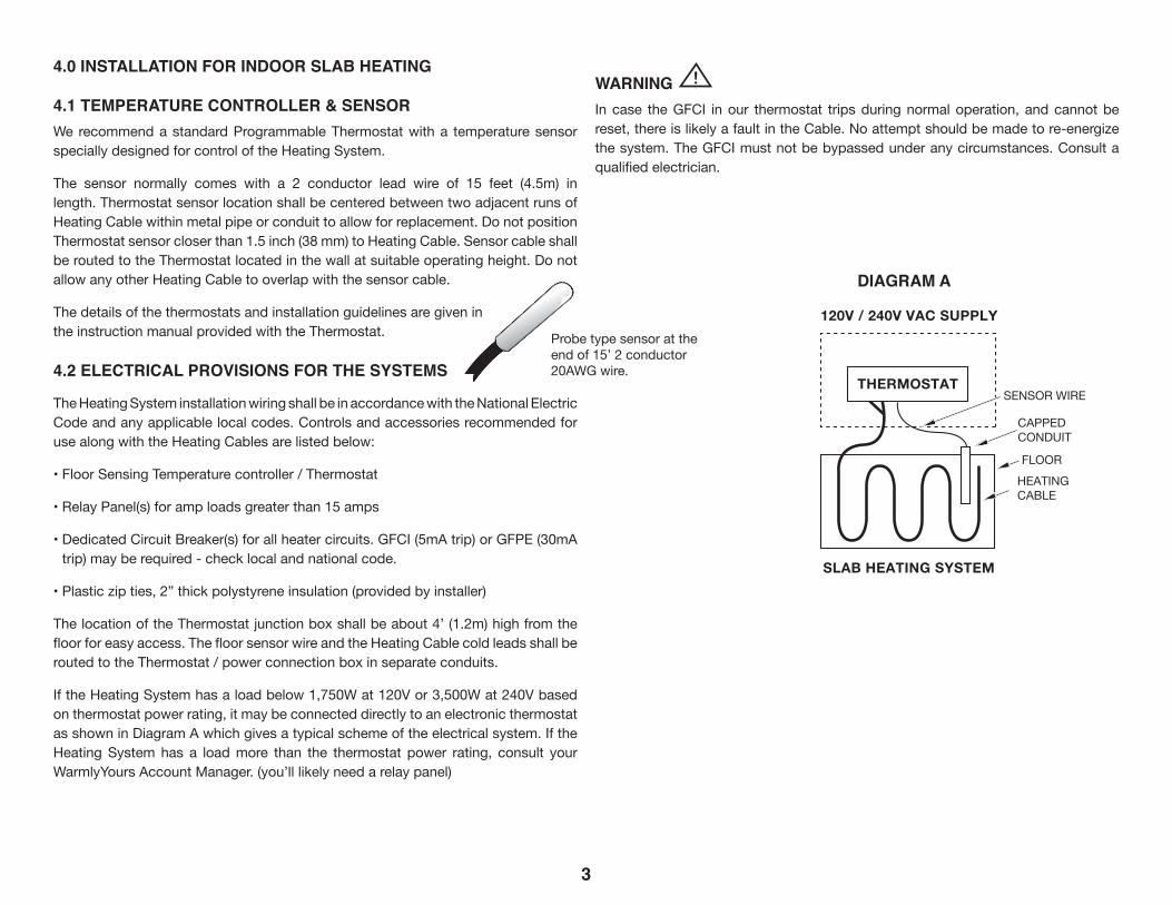
4.1 TEMPERATURE CONTROLLER & SENSORWe recommend a standard Programmable Thermostat with a temperature sensor specially designed for control of the Heating System.
The sensor normally comes with a 2 conductor lead wire of 15 feet (4.5m) in length. Thermostat sensor location shall be centered between two adjacent runs of Heating Cable within metal pipe or conduit to allow for replacement. Do not position Thermostat sensor closer than 1.5 inch (38 mm) to Heating Cable. Sensor cable shall be routed to the Thermostat located in the wall at suitable operating height. Do not allow any other Heating Cable to overlap with the sensor cable.
The details of the thermostats and installation guidelines are given in the instruction manual provided with the Thermostat.
4.2 ELECTRICAL PROVISIONS FOR THE SYSTEMS
The Heating System installation wiring shall be in accordance with the National Electric Code and any applicable local codes. Controls and accessories recommended for use along with the Heating Cables are listed below:
• Floor Sensing Temperature controller / Thermostat
• Relay Panel(s) for amp loads greater than 15 amps
• Dedicated Circuit Breaker(s) for all heater circuits. GFCI (5mA trip) or GFPE (30mA trip) may be required - check local and national code.
• Plastic zip ties, 2” thick polystyrene insulation (provided by installer)
The location of the Thermostat junction box shall be about 4’ (1.2m) high from the floor for easy access. The floor sensor wire and the Heating Cable cold leads shall be routed to the Thermostat / power connection box in separate conduits.
If the Heating System has a load below 1,750W at 120V or 3,500W at 240V based on thermostat power rating, it may be connected directly to an electronic thermostat as shown in Diagram A which gives a typical scheme of the electrical system. If the Heating System has a load more than the thermostat power rating, consult your WarmlyYours Account Manager. (you’ll likely need a relay panel)
WARNING In case the GFCI in our thermostat trips during normal operation, and cannot be reset, there is likely a fault in the Cable. No attempt should be made to re-energize the system. The GFCI must not be bypassed under any circumstances. Consult a qualified electrician.
3
2’ (61cm)or
3’ (91cm)
Length 5’ (152cm) min 50’ (1524cm) max
20’ (610cm) Cold Lead
Outer Sheath PVC/Pololefin
Polyester Sheath
Metal Sheath (Copper/Galvanised Steel/Cladded Steel)
Primary Insulation (Fluoropolymer)
Heating Conductor (Solid/Multistrand)
10"(251mm)
3"(8cm)
20’ (610cm) Cold Lead
HEATINGCABLE
FLOOR
SENSOR WIRE
CAPPED CONDUIT
1/4” (6mm) Twin-conductor Heating Cable
SLAB HEATING SYSTEM
THERMOSTAT
SNOW MELT MAT
120 VAC SUPPLY
120V / 240V VAC SUPPLY
120 VACor
240 VACRELAYPANEL
SCV-120CONTROL
SENSOR HEATINGCABLE
FLOOR
SNOW MELT MAT
THERMOSTATP N E
2’ (61cm)or
3’ (91cm)
Length 5’ (152cm) min 50’ (1524cm) max
20’ (610cm) Cold Lead
Outer Sheath PVC/Pololefin
Polyester Sheath
Metal Sheath (Copper/Galvanised Steel/Cladded Steel)
Primary Insulation (Fluoropolymer)
Heating Conductor (Solid/Multistrand)
10"(251mm)
3"(8cm)
20’ (610cm) Cold Lead
HEATINGCABLE
FLOOR
SENSOR WIRE
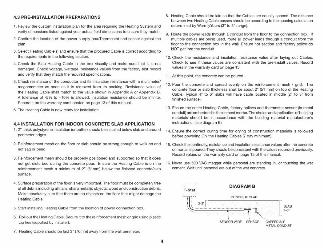
SENSOR WIRE SENSOR
CONCRETE SLAB
CAPPED 3/4”METAL CONDUIT
2-3”SLAB4-6”
CAPPED CONDUIT
1/4” (6mm) Twin-conductor Heating Cable
HEATING SYSTEM
THERMOSTAT
SNOW MELT MAT
120 VAC SUPPLY
110V / 230V AC SUPPLY
120 VACor
240 VACRELAYPANEL
SCV-120CONTROL
SENSOR HEATINGCABLE
FLOOR
SNOW MELT MAT
THERMOSTATP N E
T-Stat
DIAGRAM A
Probe type sensor at the end of 15’ 2 conductor 20AWG wire.
4.3 PRE-INSTALLATION PREPARATIONS
1. Review the custom installation plan for the area requiring the Heating System and verify dimensions listed against your actual field dimensions to ensure they match.
2. Confirm the location of the power supply box/Thermostat and sensor against the plan.
3. Select Heating Cable(s) and ensure that the procured Cable is correct according to the requirements in the following section.
4. Check the Slab Heating Cable in the box visually and make sure that it is not damaged. Check voltage, wattage, resistance values from the factory test record and verify that they match the required specifications.
5. Check resistance of the conductor and its insulation resistance with a multimeter/megohmmeter as soon as it is removed from its packing. Resistance value of the Heating Cable shall match to the value shown in Appendix A or Appendix B. A tolerance of -5% to +10% is allowed. Insulation resistance should be infinite. Record it on the warranty card located on page 13 of this manual.
6. The Heating Cable is now ready for installation.
4.4 INSTALLATION FOR INDOOR CONCRETE SLAB APPLICATION1. 2” thick polystyrene insulation (or better) should be installed below slab and around
perimeter edges.
2. Reinforcement mesh on the floor or slab should be strong enough to walk on and not sag or bend.
3. Reinforcement mesh should be properly positioned and supported so that it does not get disturbed during the concrete pour. Ensure the Heating Cable is on the reinforcement mesh a minimum of 2” (51mm) below the finished concrete/slab surface.
4. Surface preparation of the floor is very important. The floor must be completely free of all debris including all nails, sharp metallic objects, wood and construction debris. Make absolutely sure that there are no objects on the floor that might damage the Heating Cable.
5. Start installing Heating Cable from the location of power connection box.
6. Roll out the Heating Cable. Secure it to the reinforcement mesh or grid using plastic zip ties (supplied by installer).
7. Heating Cable should be laid 3” (76mm) away from the wall perimeter.
8. Heating Cable should be laid so that the Cables are equally spaced. The distance between two Heating Cable passes should be according to the spacing calculation determined by WarmlyYours (3” to 5” range).
9. Route the power leads through a conduit from the floor to the connection box. If multiple cables are being used, route all power leads through a conduit from the floor to the connection box in the wall. Ensure hot section and factory splice do NOT get into the conduit
10. Check the resistance and insulation resistance value after laying out Cables. Check to see if these values are consistent with the pre-install values. Record values in the warranty card on page 13.
11. At this point, the concrete can be poured.
12. Pour the concrete and spread evenly on the reinforcement mesh / grid. The concrete floor or slab thickness shall be about 2” (51 mm) on top of the Heating Cable. Typical 4” to 6” slabs will have cable located in middle (2” to 3” from finished surface).
13. Ensure the entire Heating Cable, factory splices and thermostat sensor (in metal conduit) are embedded in the cement mortar. The choice and application of building materials should be in accordance with the building material manufacturer’s instructions. (see diagram B)
14. Ensure the correct curing time for drying of construction materials is followed before powering ON the Heating Cables (7 day minimum).
15. Check the continuity, resistance and insulation resistance values after the concrete or mortar is poured. They should be consistent with the values recorded previously. Record values on the warranty card on page 13 of this manual.
16. Never use 500 VAC megger while personal are standing in, or touching the wet cement. Wait until personal are out of the wet concrete.
4
2’ (61cm)or
3’ (91cm)
Length 5’ (152cm) min 50’ (1524cm) max
20’ (610cm) Cold Lead
Outer Sheath PVC/Pololefin
Polyester Sheath
Metal Sheath (Copper/Galvanised Steel/Cladded Steel)
Primary Insulation (Fluoropolymer)
Heating Conductor (Solid/Multistrand)
10"(251mm)
3"(8cm)
20’ (610cm) Cold Lead
HEATINGCABLE
FLOOR
SENSOR WIRE
SENSOR WIRE SENSOR
CONCRETE SLAB
CAPPED 3/4”METAL CONDUIT
2-3”SLAB4-6”
CAPPED CONDUIT
1/4” (6mm) Twin-conductor Heating Cable
HEATING SYSTEM
THERMOSTAT
SNOW MELT MAT
120 VAC SUPPLY
110V / 230V AC SUPPLY
120 VACor
240 VACRELAYPANEL
SCV-120CONTROL
SENSOR HEATINGCABLE
FLOOR
SNOW MELT MAT
THERMOSTATP N E
T-StatDIAGRAM B
5
4.5 OPERATING TIPS
1. Energy consumption will vary depending on ambient temperature and building insulation. For lower energy consumption, use a 7-day Programmable Thermostat control.
2. Energy consumption can be minimized by turning the system OFF when heating is not required, but extra time will be required for the floor to warm up once the system is turned ON again.
3. Avoid placing objects like thick mats, rugs, floor level furniture and mattresses on the heated floor, especially in the area where the floor temperature sensor is located. These restrict the transfer of heat away from the Cables and result in the floor area beneath them being warmer than other areas.
4. Avoid Mats with rubber or vinyl type backing as these may decompose with heat and could stain flooring.
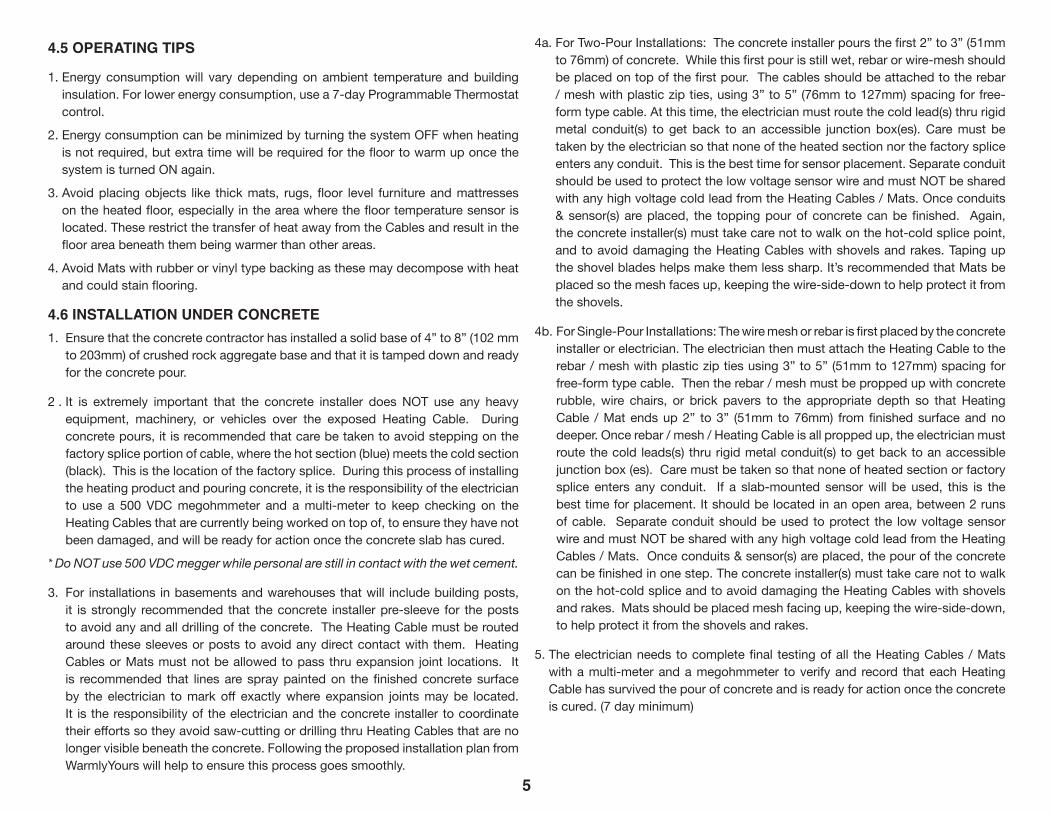
4.6 INSTALLATION UNDER CONCRETE1. Ensure that the concrete contractor has installed a solid base of 4” to 8” (102 mm
to 203mm) of crushed rock aggregate base and that it is tamped down and ready for the concrete pour.
2 . It is extremely important that the concrete installer does NOT use any heavy equipment, machinery, or vehicles over the exposed Heating Cable. During concrete pours, it is recommended that care be taken to avoid stepping on the factory splice portion of cable, where the hot section (blue) meets the cold section (black). This is the location of the factory splice. During this process of installing the heating product and pouring concrete, it is the responsibility of the electrician to use a 500 VDC megohmmeter and a multi-meter to keep checking on the Heating Cables that are currently being worked on top of, to ensure they have not been damaged, and will be ready for action once the concrete slab has cured.
* Do NOT use 500 VDC megger while personal are still in contact with the wet cement.
3. For installations in basements and warehouses that will include building posts, it is strongly recommended that the concrete installer pre-sleeve for the posts to avoid any and all drilling of the concrete. The Heating Cable must be routed around these sleeves or posts to avoid any direct contact with them. Heating Cables or Mats must not be allowed to pass thru expansion joint locations. It is recommended that lines are spray painted on the finished concrete surface by the electrician to mark off exactly where expansion joints may be located. It is the responsibility of the electrician and the concrete installer to coordinate their efforts so they avoid saw-cutting or drilling thru Heating Cables that are no longer visible beneath the concrete. Following the proposed installation plan from WarmlyYours will help to ensure this process goes smoothly.
4a. For Two-Pour Installations: The concrete installer pours the first 2” to 3” (51mm to 76mm) of concrete. While this first pour is still wet, rebar or wire-mesh should be placed on top of the first pour. The cables should be attached to the rebar / mesh with plastic zip ties, using 3” to 5” (76mm to 127mm) spacing for free-form type cable. At this time, the electrician must route the cold lead(s) thru rigid metal conduit(s) to get back to an accessible junction box(es). Care must be taken by the electrician so that none of the heated section nor the factory splice enters any conduit. This is the best time for sensor placement. Separate conduit should be used to protect the low voltage sensor wire and must NOT be shared with any high voltage cold lead from the Heating Cables / Mats. Once conduits & sensor(s) are placed, the topping pour of concrete can be finished. Again, the concrete installer(s) must take care not to walk on the hot-cold splice point, and to avoid damaging the Heating Cables with shovels and rakes. Taping up the shovel blades helps make them less sharp. It’s recommended that Mats be placed so the mesh faces up, keeping the wire-side-down to help protect it from the shovels.
4b. For Single-Pour Installations: The wire mesh or rebar is first placed by the concrete installer or electrician. The electrician then must attach the Heating Cable to the rebar / mesh with plastic zip ties using 3” to 5” (51mm to 127mm) spacing for free-form type cable. Then the rebar / mesh must be propped up with concrete rubble, wire chairs, or brick pavers to the appropriate depth so that Heating Cable / Mat ends up 2” to 3” (51mm to 76mm) from finished surface and no deeper. Once rebar / mesh / Heating Cable is all propped up, the electrician must route the cold leads(s) thru rigid metal conduit(s) to get back to an accessible junction box (es). Care must be taken so that none of heated section or factory splice enters any conduit. If a slab-mounted sensor will be used, this is the best time for placement. It should be located in an open area, between 2 runs of cable. Separate conduit should be used to protect the low voltage sensor wire and must NOT be shared with any high voltage cold lead from the Heating Cables / Mats. Once conduits & sensor(s) are placed, the pour of the concrete can be finished in one step. The concrete installer(s) must take care not to walk on the hot-cold splice and to avoid damaging the Heating Cables with shovels and rakes. Mats should be placed mesh facing up, keeping the wire-side-down, to help protect it from the shovels and rakes.
5. The electrician needs to complete final testing of all the Heating Cables / Mats with a multi-meter and a megohmmeter to verify and record that each Heating Cable has survived the pour of concrete and is ready for action once the concrete is cured. (7 day minimum)
2’ (61cm)or
3’ (91cm)
Length 5’ (152cm) min 50’ (1524cm) max
20’ (610cm) Cold Lead
Outer Sheath PVC/Pololefin
Polyester Sheath
Metal Sheath (Copper/Galvanised Steel/Cladded Steel)
Primary Insulation (Fluoropolymer)
Heating Conductor (Solid/Multistrand)
10"(251mm)
3"(8cm)
20’ (610cm) Cold Lead
SENSOR HEATINGCABLE
FLOOR
1/4” (6mm) Twin-conductor Heating Cable
HEATING SYSTEM
110V / 230V AC SUPPLY
THERMOSTAT
SENSOR HEATINGCABLE
FLOOR
SNOW MELT MAT
110V / 230V AC SUPPLY
THERMOSTAT
P N E
6
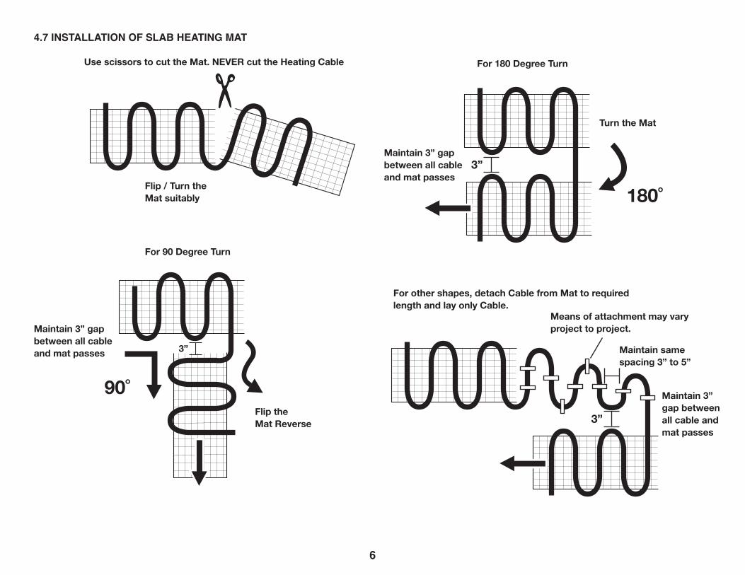
Use scissors to cut the Mat. NEVER cut the Heating Cable For 180 Degree Turn
180˚3”
3”
90˚
For other shapes, detach Cable from Mat to required length and lay only Cable.
Maintain 3” gap between all cable and mat passes
Maintain 3” gap between all cable and mat passes
Maintain same spacing 3” to 5”
Maintain 3” gap between all cable and mat passes
Means of attachment may vary project to project.
For 90 Degree Turn
Flip the Mat Reverse
Turn the Mat
Flip / Turn the Mat suitably
4.7 INSTALLATION OF SLAB HEATING MAT
3”
7
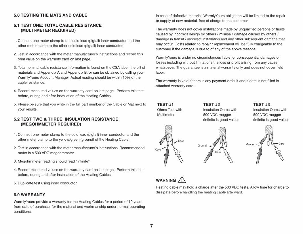
5.0 TESTING THE MATS AND CABLE
5.1 TEST ONE: TOTAL CABLE RESISTANCE (MULTI-METER REQUIRED)
1. Connect one meter clamp to one cold lead (pigtail) inner conductor and the other meter clamp to the other cold lead (pigtail) inner conductor.
2. Test in accordance with the meter manufacturer’s instructions and record this ohm value on the warranty card on last page.
3. Total nominal cable resistance information is found on the CSA label, the bill of materials and Appendix A and Appendix B, or can be obtained by calling your WarmlyYours Account Manager. Actual reading should be within 10% of the cable resistance.
4. Record measured values on the warranty card on last page. Perform this test before, during and after installation of the Heating Cables.
5. Please be sure that you write in the full part number of the Cable or Mat next to your results.
5.2 TEST TWO & THREE: INSULATION RESISTANCE (MEGOHMMETER REQUIRED)
1. Connect one meter clamp to the cold lead (pigtail) inner conductor and the other meter clamp to the yellow/green (ground) of the Heating Cable.
2. Test in accordance with the meter manufacturer’s instructions. Recommended meter is a 500 VDC megohmmeter.
3. Megohmmeter reading should read “infinite”.
4. Record measured values on the warranty card on last page. Perform this test before, during and after installation of the Heating Cables.
5. Duplicate test using inner conductor.
6.0 WARRANTYWarmlyYours provide a warranty for the Heating Cables for a period of 10 years from date of purchase, for the material and workmanship under normal operating conditions.
In case of defective material, WarmlyYours obligation will be limited to the repair or supply of new material, free of charge to the customer.
The warranty does not cover installations made by unqualified persons or faults caused by incorrect design by others / misuse / damage caused by others / damage in transit / incorrect installation and any other subsequent damage that may occur. Costs related to repair / replacement will be fully chargeable to the customer if the damage is due to of any of the above reasons.
WarmlyYours is under no circumstances liable for consequential damages or losses including without limitations the loss or profit arising from any cause whatsoever. The guarantee is a material warranty only and does not cover field labor.
The warranty is void if there is any payment default and if data is not filled in attached warranty card.
WARNING Heating cable may hold a charge after the 500 VDC tests. Allow time for charge to dissipate before handling the heating cable afterward.
Yellow or Red
Ground Ground
Yellow or Red
BlackBlack
Core
Ground Ground
Core
CoreCore
TEST #1Ohms Test with Multimeter
TEST #2Insulation Ohms with 500 VDC megger(Infinite is good value)
TEST #3Insulation Ohms with 500 VDC megger(Infinite is good value)
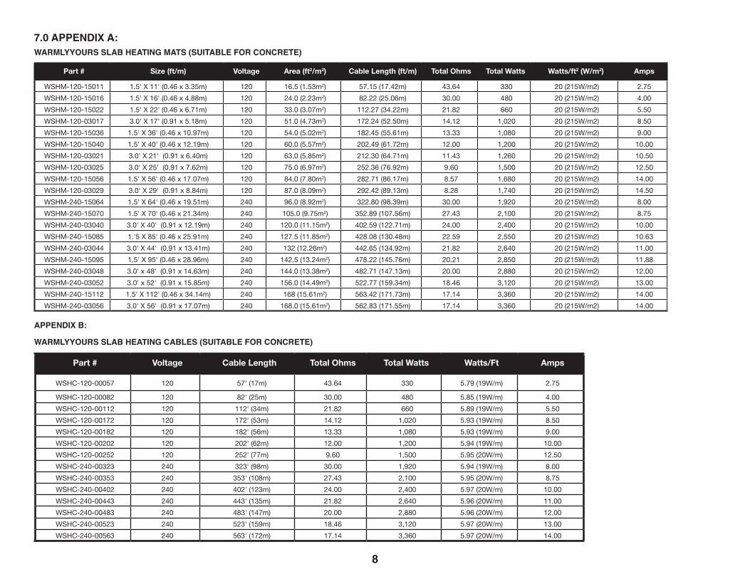
7.0 APPENDIX A:WARMLYYOURS SLAB HEATING MATS (SUITABLE FOR CONCRETE)
Part # Size (ft/m) Voltage Area (ft2/m2) Cable Length (ft/m) Total Ohms Total Watts Watts/ft2 (W/m2) Amps
WSHM-120-15011 1.5' X 11' (0.46 x 3.35m) 120 16.5 (1.53m2) 57.15 (17.42m) 43.64 330 20 (215W/m2) 2.75WSHM-120-15016 1.5' X 16' (0.46 x 4.88m) 120 24.0 (2.23m2) 82.22 (25.06m) 30.00 480 20 (215W/m2) 4.00WSHM-120-15022 1.5' X 22' (0.46 x 6.71m) 120 33.0 (3.07m2) 112.27 (34.22m) 21.82 660 20 (215W/m2) 5.50WSHM-120-03017 3.0' X 17' (0.91 x 5.18m) 120 51.0 (4.73m2) 172.24 (52.50m) 14.12 1,020 20 (215W/m2) 8.50WSHM-120-15036 1.5' X 36' (0.46 x 10.97m) 120 54.0 (5.02m2) 182.45 (55.61m) 13.33 1,080 20 (215W/m2) 9.00WSHM-120-15040 1.5' X 40' (0.46 x 12.19m) 120 60.0 (5.57m2) 202.49 (61.72m) 12.00 1,200 20 (215W/m2) 10.00WSHM-120-03021 3.0' X 21' (0.91 x 6.40m) 120 63.0 (5.85m2) 212.30 (64.71m) 11.43 1,260 20 (215W/m2) 10.50WSHM-120-03025 3.0' X 25' (0.91 x 7.62m) 120 75.0 (6.97m2) 252.36 (76.92m) 9.60 1,500 20 (215W/m2) 12.50WSHM-120-15056 1.5' X 56' (0.46 x 17.07m) 120 84.0 (7.80m2) 282.71 (86.17m) 8.57 1,680 20 (215W/m2) 14.00WSHM-120-03029 3.0' X 29' (0.91 x 8.84m) 120 87.0 (8.09m2) 292.42 (89.13m) 8.28 1,740 20 (215W/m2) 14.50WSHM-240-15064 1.5' X 64' (0.46 x 19.51m) 240 96.0 (8.92m2) 322.80 (98.39m) 30.00 1,920 20 (215W/m2) 8.00WSHM-240-15070 1.5' X 70' (0.46 x 21.34m) 240 105.0 (9.75m2) 352.89 (107.56m) 27.43 2,100 20 (215W/m2) 8.75WSHM-240-03040 3.0' X 40' (0.91 x 12.19m) 240 120.0 (11.15m2) 402.59 (122.71m) 24.00 2,400 20 (215W/m2) 10.00WSHM-240-15085 1.'5 X 85' (0.46 x 25.91m) 240 127.5 (11.85m2) 428.08 (130.48m) 22.59 2,550 20 (215W/m2) 10.63WSHM-240-03044 3.0' X 44' (0.91 x 13.41m) 240 132 (12.26m2) 442.65 (134.92m) 21.82 2,640 20 (215W/m2) 11.00WSHM-240-15095 1.5' X 95' (0.46 x 28.96m) 240 142.5 (13.24m2) 478.22 (145.76m) 20.21 2,850 20 (215W/m2) 11.88WSHM-240-03048 3.0' x 48' (0.91 x 14.63m) 240 144.0 (13.38m2) 482.71 (147.13m) 20.00 2,880 20 (215W/m2) 12.00WSHM-240-03052 3.0' x 52' (0.91 x 15.85m) 240 156.0 (14.49m2) 522.77 (159.34m) 18.46 3,120 20 (215W/m2) 13.00WSHM-240-15112 1.5' X 112' (0.46 x 34.14m) 240 168 (15.61m2) 563.42 (171.73m) 17.14 3,360 20 (215W/m2) 14.00WSHM-240-03056 3.0' X 56' (0.91 x 17.07m) 240 168.0 (15.61m2) 562.83 (171.55m) 17.14 3,360 20 (215W/m2) 14.00
8
APPENDIX B:
WARMLYYOURS SLAB HEATING CABLES (SUITABLE FOR CONCRETE)
Part # Voltage Cable Length Total Ohms Total Watts Watts/Ft Amps
WSHC-120-00057 120 57' (17m) 43.64 330 5.79 (19W/m) 2.75
WSHC-120-00082 120 82' (25m) 30.00 480 5.85 (19W/m) 4.00WSHC-120-00112 120 112' (34m) 21.82 660 5.89 (19W/m) 5.50WSHC-120-00172 120 172' (53m) 14.12 1,020 5.93 (19W/m) 8.50WSHC-120-00182 120 182' (56m) 13.33 1,080 5.93 (19W/m) 9.00WSHC-120-00202 120 202' (62m) 12.00 1,200 5.94 (19W/m) 10.00WSHC-120-00252 120 252' (77m) 9.60 1,500 5.95 (20W/m) 12.50WSHC-240-00323 240 323' (98m) 30.00 1,920 5.94 (19W/m) 8.00WSHC-240-00353 240 353' (108m) 27.43 2,100 5.95 (20W/m) 8.75WSHC-240-00402 240 402' (123m) 24.00 2,400 5.97 (20W/m) 10.00WSHC-240-00443 240 443' (135m) 21.82 2,640 5.96 (20W/m) 11.00WSHC-240-00483 240 483' (147m) 20.00 2,880 5.96 (20W/m) 12.00WSHC-240-00523 240 523' (159m) 18.46 3,120 5.97 (20W/m) 13.00WSHC-240-00563 240 563' (172m) 17.14 3,360 5.97 (20W/m) 14.00
9
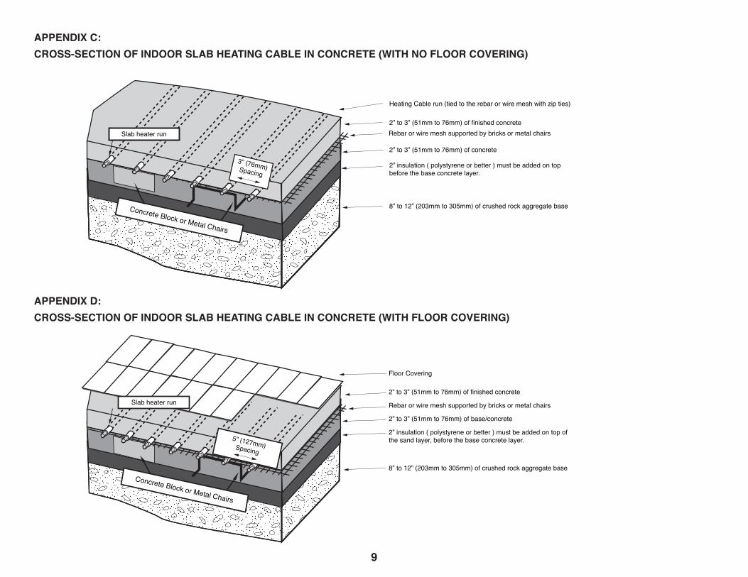
APPENDIX D:CROSS-SECTION OF INDOOR SLAB HEATING CABLE IN CONCRETE (WITH FLOOR COVERING)
APPENDIX C:CROSS-SECTION OF INDOOR SLAB HEATING CABLE IN CONCRETE (WITH NO FLOOR COVERING)
10
2” to 3”(51mm to 76mm) of finished asphalt.
1.5” to 2” (38mm to 51mm) of base/primer asphalt
4” to 8” (102mm to 203mm) of crushed aggregate
Wire mesh above or below Heating Cables
3” (76mm) Spacing
2” to 3” (51mm to 76mm) of finished concrete
2” to 3” (51mm to 76mm) of concrete
8” to 12” (203mm to 305mm) of crushed rock aggregate base
Rebar or wire mesh supported by bricks or metal chairs
1” to 2” (51mm to 76mm) of finished mortar
Brick and Stone Pavers must NOT be any thickerthan 2.5” (63.5mm).
Floor Covering
4” to 8” (102mm to 203mm) of crushed rock aggregate base
Rebar or wire mesh staked to aggregrate base
2” to 3” (51mm to 76mm) of finished concrete
2” to 3” (51mm to 76mm) of base/concrete
2” insulation ( polystyrene or better ) must be added on top of the sand layer, before the base concrete layer.
8” to 12” (203mm to 305mm) of crushed rock aggregate base
Rebar or wire mesh supported by bricks or metal chairs
2” insulation ( polystyrene or better ) must be added on top before the base concrete layer.
3” (76mm) Spacing
WHCA heater run
WHCA heater run
Slab heater run
3” (76mm) Spacing
5” (127mm) Spacing
Heating Cable run (tied to the rebar or wire mesh with zip ties)
Slab heater run
Concrete Block or Metal Chairs
Concrete Block or Metal Chairs
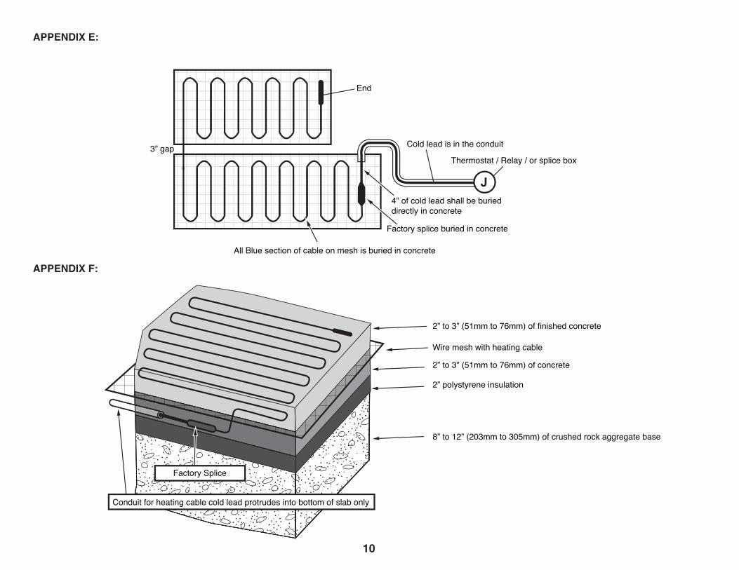
APPENDIX E:
APPENDIX F:
10
2.5” in (6.3cm) maximumthickness brick or concrete paver
1.5” sand, stone dust or mortar
Plastic tie wrap
4 in (10) or 6 in (15) square 10 gauge wire mesh
Level of heating cable
2” (5 cm)
3” (7.6 cm)
8”-12” crushed rock aggregate
3” gap
End
Cold lead is in the conduit
Thermostat / Relay / or splice box
4” of cold lead shall be buried directly in concrete
All Blue section of cable on mesh is buried in concrete
Factory splice buried in concrete
Righthot/cold joints 6 in (15 cm) apart and 6 in (15 cm) from slab edge
Wronghot/cold joints installed on slab edge
Wronghot/cold joints bunched
concrete wall
Junction box mounted on inside wallCable identification tag(within 3 in (7.5cm) of NPT connector)Cold lead
Conduit
Expansion joint
Heated Slab
ConduitHot/Cold
jointHeating
cable
Cold leads protected with 1-1/2in (3.8cm)minimum nonmetallic conduitwhere they emerge from slab
Conduit for slab temperature sensor
Corner rounded off to prevent cable damage
1.2 in (1.3 cm) wide steel prepunched strapping
Wrongcold joints
unche
Wrongcold joints
stalleslab
Cable must be at least 4 in (10 cm) from rail post
Cable must be at least 4 in (10 cm) from edge
2” to 3” (51mm to 76mm) of finished concrete
2” to 3” (51mm to 76mm) of concrete
8” to 12” (203mm to 305mm) of crushed rock aggregate base
Wire mesh with heating cable
4” thick sand over crushed rock aggregate
2” polystyrene insulation
Factory Splice
J
Conduit for heating cable cold lead protrudes into bottom of slab only
2.5” in (6.3cm) maximumthickness brick or concrete paver
1.5” sand, stone dust or mortar
Plastic tie wrap
4 in (10) or 6 in (15) square 10 gauge wire mesh
Level of heating cable
2” (5 cm)
3” (7.6 cm)
8”-12” crushed rock aggregate
3” gap
End
Cold lead is in the conduit
Thermostat / Relay / or splice box
4” of cold lead shall be buried directly in concrete
All Blue section of cable on mesh is buried in concrete
Factory splice buried in concrete
Righthot/cold joints 6 in (15 cm) apart and 6 in (15 cm) from slab edge
Wronghot/cold joints installed on slab edge
Wronghot/cold joints bunched
concrete wall
Junction box mounted on inside wallCable identification tag(within 3 in (7.5cm) of NPT connector)Cold lead
Conduit
Expansion joint
Heated Slab
ConduitHot/Cold
jointHeating
cable
Cold leads protected with 1-1/2in (3.8cm)minimum nonmetallic conduitwhere they emerge from slab
Conduit for slab temperature sensor
Corner rounded off to prevent cable damage
1.2 in (1.3 cm) wide steel prepunched strapping
Wrongcold joints
unche
Wrongcold joints
stalleslab
Cable must be at least 4 in (10 cm) from rail post
Cable must be at least 4 in (10 cm) from edge
2” to 3” (51mm to 76mm) of finished concrete
2” to 3” (51mm to 76mm) of concrete
8” to 12” (203mm to 305mm) of crushed rock aggregate base
Wire mesh with heating cable
2” polystyrene insulation
Factory Splice
J
Conduit for heating cable cold lead protrudes into bottom of slab only
Installation Support • No Nonsense™ W
arranty •�(800) 875-5285 • www.Warm
lyYours.com
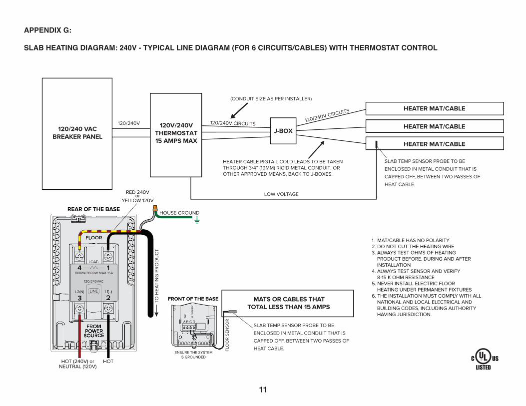
APPENDIX G:
SLAB HEATING DIAGRAM: 240V - TYPICAL LINE DIAGRAM (FOR 6 CIRCUITS/CABLES) WITH THERMOSTAT CONTROL
Installation Support • (800) 875-5285 • www.WarmlyYours.com
120/240V CIRCUITS
LOW VOLTAGE
HEATER CABLE PIGTAIL COLD LEADS TO BE TAKENTHROUGH 3/4” (19MM) RIGID METAL CONDUIT, OROTHER APPROVED MEANS, BACK TO J-BOXES.
SLAB TEMP SENSOR PROBE TO BE
ENCLOSED IN METAL CONDUIT THAT IS
CAPPED OFF, BETWEEN TWO PASSES OF
HEAT CABLE.
(CONDUIT SIZE AS PER INSTALLER)
120/240V CIRCUITS120/240V
J-BOX
HEATER MAT/CABLE
HEATER MAT/CABLE
HEATER MAT/CABLE
120/240 VACBREAKER PANEL
120V/240VTHERMOSTAT15 AMPS MAX
MATS OR CABLES THATTOTAL LESS THAN 15 AMPS
SLAB TEMP SENSOR PROBE TO BE
ENCLOSED IN METAL CONDUIT THAT IS
CAPPED OFF, BETWEEN TWO PASSES OF
HEAT CABLE.ENSURE THE SYSTEM
IS GROUNDED
HOUSE GROUND
1. MAT/CABLE HAS NO POLARITY2. DO NOT CUT THE HEATING WIRE3. ALWAYS TEST OHMS OF HEATING PRODUCT BEFORE, DURING AND AFTER INSTALLATION4. ALWAYS TEST SENSOR AND VERIFY 8-15 K OHM RESISTANCE5. NEVER INSTALL ELECTRIC FLOOR HEATING UNDER PERMANENT FIXTURES6. THE INSTALLATION MUST COMPLY WITH ALL NATIONAL AND LOCAL ELECTRICAL AND BUILDING CODES, INCLUDING AUTHORITY HAVING JURISDICTION.
HOT (240V) orNEUTRAL (120V)
HOT
FLOOR
FRONT OF THE BASE
FLO
OR
SE
NS
OR
TO H
EA
TIN
G P
RO
DU
CT
LOAD
14
3L2(N) LINE
1800W/3600W MAX 15A
120/240VAC
FLOOR
LOAD
14
3L2(N) LINE
1800W/3600W MAX 15A
120/240VAC
REAR OF THE BASE
A B C D
out
in /
sens
orr
A B C D
out
in /
sens
orr
LISTEDC US
WIRING DIAGRAMFor 120V & 240V Slab Heating Products with
nSpire Touch Wi-Fi (UWG4), nSpire Touch (UDG4),nHance (UDG), nTrust (UTN4), nJoin (USG)
RED 240Vor
YELLOW 120V
11 12
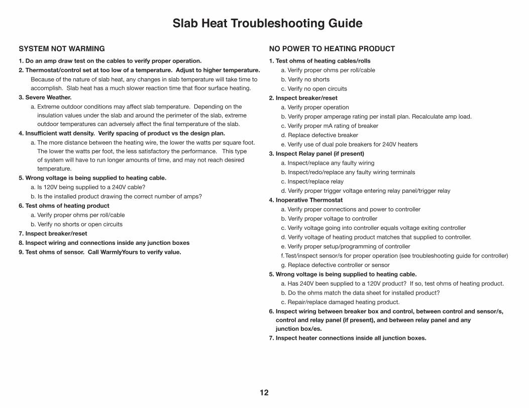
SYSTEM NOT WARMING 1. Do an amp draw test on the cables to verify proper operation.2. Thermostat/control set at too low of a temperature. Adjust to higher temperature.
Because of the nature of slab heat, any changes in slab temperature will take time to accomplish. Slab heat has a much slower reaction time that floor surface heating.
3. Severe Weather.a. Extreme outdoor conditions may affect slab temperature. Depending on the
insulation values under the slab and around the perimeter of the slab, extreme outdoor temperatures can adversely affect the final temperature of the slab.
4. Insufficient watt density. Verify spacing of product vs the design plan.a. The more distance between the heating wire, the lower the watts per square foot.
The lower the watts per foot, the less satisfactory the performance. This type of system will have to run longer amounts of time, and may not reach desired temperature.
5. Wrong voltage is being supplied to heating cable. a. Is 120V being supplied to a 240V cable?b. Is the installed product drawing the correct number of amps?
6. Test ohms of heating producta. Verify proper ohms per roll/cableb. Verify no shorts or open circuits
7. Inspect breaker/reset8. Inspect wiring and connections inside any junction boxes9. Test ohms of sensor. Call WarmlyYours to verify value.
NO POWER TO HEATING PRODUCT1. Test ohms of heating cables/rolls
a. Verify proper ohms per roll/cableb. Verify no shortsc. Verify no open circuits
2. Inspect breaker/reseta. Verify proper operationb. Verify proper amperage rating per install plan. Recalculate amp load.c. Verify proper mA rating of breakerd. Replace defective breakere. Verify use of dual pole breakers for 240V heaters
3. Inspect Relay panel (if present)a. Inspect/replace any faulty wiringb. Inspect/redo/replace any faulty wiring terminalsc. Inspect/replace relayd. Verify proper trigger voltage entering relay panel/trigger relay
4. Inoperative Thermostata. Verify proper connections and power to controllerb. Verify proper voltage to controllerc. Verify voltage going into controller equals voltage exiting controllerd. Verify voltage of heating product matches that supplied to controller.e. Verify proper setup/programming of controllerf. Test/inspect sensor/s for proper operation (see troubleshooting guide for controller)g. Replace defective controller or sensor
5. Wrong voltage is being supplied to heating cable. a. Has 240V been supplied to a 120V product? If so, test ohms of heating product.b. Do the ohms match the data sheet for installed product?c. Repair/replace damaged heating product.
6. Inspect wiring between breaker box and control, between control and sensor/s, control and relay panel (if present), and between relay panel and any junction box/es.
7. Inspect heater connections inside all junction boxes.
Slab Heat Troubleshooting Guide
12
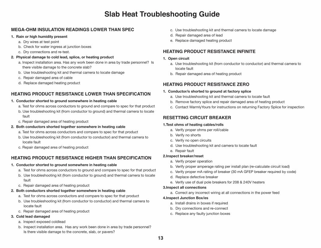
MEGA-OHM INSULATION READINGS LOWER THAN SPEC1. Rain or high humidity present
a. Dry wires at test point b. Check for water ingress at junction boxes c. Dry connections and re-test.
2. Physical damage to cold lead, splice, or heating producta. Inspect installation area. Has any work been done in area by trade personnel? Is
there visible damage to the concrete slab?b. Use troubleshooting kit and thermal camera to locate damagec. Repair damaged area of cabled. Replace damaged heating product
HEATING PRODUCT RESISTANCE LOWER THAN SPECIFICATION1. Conductor shorted to ground somewhere in heating cable
a. Test for ohms across conductors to ground and compare to spec for that productb. Use troubleshooting kit (from conductor to ground) and thermal camera to locate
faultc. Repair damaged area of heating product
2. Both conductors shorted together somewhere in heating cablea. Test for ohms across conductors and compare to spec for that productb. Use troubleshooting kit (from conductor to conductor) and thermal camera to
locate faultc. Repair damaged area of heating product
HEATING PRODUCT RESISTANCE HIGHER THAN SPECIFICATION1. Conductor shorted to ground somewhere in heating cable
a. Test for ohms across conductors to ground and compare to spec for that productb. Use troubleshooting kit (from conductor to ground) and thermal camera to locate
faultc. Repair damaged area of heating product
2. Both conductors shorted together somewhere in heating cablea. Test for ohms across conductors and compare to spec for that productb. Use troubleshooting kit (from conductor to conductor) and thermal camera to
locate faultc. Repair damaged area of heating product
3. Cold lead damageda. Inspect exposed coldleadb. Inspect installation area. Has any work been done in area by trade personnel?
Is there visible damage to the concrete, slab, or pavers?
c. Use troubleshooting kit and thermal camera to locate damaged. Repair damaged area of leade. Replace damaged heating product
HEATING PRODUCT RESISTANCE INFINITE1. Open circuit
a. Use troubleshooting kit (from conductor to conductor) and thermal camera to locate fault
b. Repair damaged area of heating product
HEATING PRODUCT RESISTANCE ZERO1. Conductor/s shorted to ground at factory splice
a. Use troubleshooting kit and thermal camera to locate faultb. Remove factory splice and repair damaged area of heating productc. Contact WarmlyYours for instructions on returning Factory Splice for inspection
RESETTING CIRCUIT BREAKER1.Test ohms of heating cables/rolls
a. Verify proper ohms per roll/cableb. Verify no shortsc. Verify no open circuitsd. Use troubleshooting kit and camera to locate faulte. Repair fault
2.Inspect breaker/reseta. Verify proper operationb. Verify proper amperage rating per install plan (re-calculate circuit load)c. Verify proper mA rating of breaker (30 mA GFEP breaker required by code)d. Replace defective breakere. Verify use of dual pole breakers for 208 & 240V heaters
3.Inspect all connections a. Correct any incorrect wiring at all connections in the power feed
4.Inspect Junction Box/esa. Install drains in boxes if requiredb. Dry connections and re-connectc. Replace any faulty junction boxes
Slab Heat Troubleshooting Guide
13
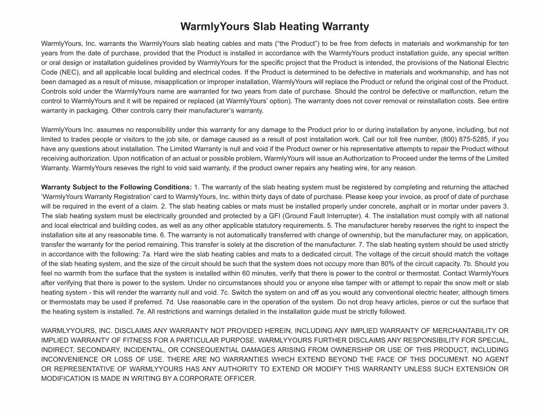
WarmlyYours Slab Heating WarrantyWarmlyYours, Inc. warrants the WarmlyYours slab heating cables and mats (“the Product”) to be free from defects in materials and workmanship for ten years from the date of purchase, provided that the Product is installed in accordance with the WarmlyYours product installation guide, any special written or oral design or installation guidelines provided by WarmlyYours for the specific project that the Product is intended, the provisions of the National Electric Code (NEC), and all applicable local building and electrical codes. If the Product is determined to be defective in materials and workmanship, and has not been damaged as a result of misuse, misapplication or improper installation, WarmlyYours will replace the Product or refund the original cost of the Product. Controls sold under the WarmlyYours name are warranted for two years from date of purchase. Should the control be defective or malfunction, return the control to WarmlyYours and it will be repaired or replaced (at WarmlyYours’ option). The warranty does not cover removal or reinstallation costs. See entire warranty in packaging. Other controls carry their manufacturer’s warranty.
WarmlyYours Inc. assumes no responsibility under this warranty for any damage to the Product prior to or during installation by anyone, including, but not limited to trades people or visitors to the job site, or damage caused as a result of post installation work. Call our toll free number, (800) 875-5285, if you have any questions about installation. The Limited Warranty is null and void if the Product owner or his representative attempts to repair the Product without receiving authorization. Upon notification of an actual or possible problem, WarmlyYours will issue an Authorization to Proceed under the terms of the Limited Warranty. WarmlyYours reseves the right to void said warranty, if the product owner repairs any heating wire, for any reason.
Warranty Subject to the Following Conditions: 1. The warranty of the slab heating system must be registered by completing and returning the attached ‘WarmlyYours Warranty Registration’ card to WarmlyYours, Inc. within thirty days of date of purchase. Please keep your invoice, as proof of date of purchase will be required in the event of a claim. 2. The slab heating cables or mats must be installed properly under concrete, asphalt or in mortar under pavers 3. The slab heating system must be electrically grounded and protected by a GFI (Ground Fault Interrupter). 4. The installation must comply with all national and local electrical and building codes, as well as any other applicable statutory requirements. 5. The manufacturer hereby reserves the right to inspect the installation site at any reasonable time. 6. The warranty is not automatically transferred with change of ownership, but the manufacturer may, on application, transfer the warranty for the period remaining. This transfer is solely at the discretion of the manufacturer. 7. The slab heating system should be used strictly in accordance with the following: 7a. Hard wire the slab heating cables and mats to a dedicated circuit. The voltage of the circuit should match the voltage of the slab heating system, and the size of the circuit should be such that the system does not occupy more than 80% of the circuit capacity. 7b. Should you feel no warmth from the surface that the system is installed within 60 minutes, verify that there is power to the control or thermostat. Contact WarmlyYours after verifying that there is power to the system. Under no circumstances should you or anyone else tamper with or attempt to repair the snow melt or slab heating system - this will render the warranty null and void. 7c. Switch the system on and off as you would any conventional electric heater, although timers or thermostats may be used if preferred. 7d. Use reasonable care in the operation of the system. Do not drop heavy articles, pierce or cut the surface that the heating system is installed. 7e. All restrictions and warnings detailed in the installation guide must be strictly followed.
WARMLYYOURS, INC. DISCLAIMS ANY WARRANTY NOT PROVIDED HEREIN, INCLUDING ANY IMPLIED WARRANTY OF MERCHANTABILITY OR IMPLIED WARRANTY OF FITNESS FOR A PARTICULAR PURPOSE. WARMLYYOURS FURTHER DISCLAIMS ANY RESPONSIBILITY FOR SPECIAL, INDIRECT, SECONDARY, INCIDENTAL, OR CONSEQUENTIAL DAMAGES ARISING FROM OWNERSHIP OR USE OF THIS PRODUCT, INCLUDING INCONVENIENCE OR LOSS OF USE. THERE ARE NO WARRANTIES WHICH EXTEND BEYOND THE FACE OF THIS DOCUMENT. NO AGENT OR REPRESENTATIVE OF WARMLYYOURS HAS ANY AUTHORITY TO EXTEND OR MODIFY THIS WARRANTY UNLESS SUCH EXTENSION OR MODIFICATION IS MADE IN WRITING BY A CORPORATE OFFICER.
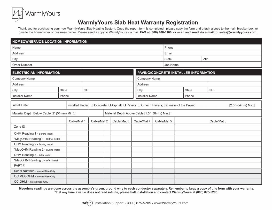
Install Date: Installed Under: q Concrete q Asphalt q Pavers q Other If Pavers, thickness of the Paver:___________________ [2.5” (64mm) Max]
Material Depth Below Cable [2” (51mm) Min.]: Material Depth Above Cable [1.5” (38mm) Min.]:
Cable/Mat 1 Cable/Mat 2 Cable/Mat 3 Cable/Mat 4 Cable/Mat 5 Cable/Mat 6
Zone ID
OHM Reading 1 - Before Install
*MegOHM Reading 1 - Before Install
OHM Reading 2 - During Install
*MegOHM Reading 2 - During Install
OHM Reading 3 - After Install
*MegOHM Reading 3 - After Install
PART #
Serial Number - Internal Use Only
QC MEGOHM - Internal Use Only
QC OHM - Internal Use Only
WarmlyYours Slab Heat Warranty RegistrationThank you for purchasing your new WarmlyYours Slab Heating System. Once the report form is completed, please copy the form and attach a copy to the main breaker box, or give to the homeowner or business owner. Please send a copy to WarmlyYours via mail, FAX at (800) 408-1100, or scan and send via e-mail to: [email protected].
Megohms readings are done across the assembly’s green, ground wire to each conductor separately. Remember to keep a copy of this form with your warranty.*If at any time a value does not read infinite, please halt installation and contact WarmlyYours at (800) 875-5285.
HOMEOWNER/JOB LOCATION INFORMATIONName Phone
Address Email
City State ZIP
Order Number Job Name
ELECTRICIAN INFORMATIONCompany Name
Address
City State ZIP
Installer Name Phone
PAVING/CONCRETE INSTALLER INFORMATIONCompany Name
Address
City State ZIP
Installer Name Phone
Installation Support • (800) 875-5285 • www.WarmlyYours.com