Embed Size (px)
Citation preview

VMAC – Vehicle Mounted Air Compressors Toll Free: 1-800-738-8622 Fax: 1-250-740-3201
1
Installation Manual for VMAC System V900105
2007 Ford F650-F750 7.2L Caterpillar C7
Inter-cooled Diesel
General Information..................................................................... 3 Before You Start ....................................................................... 3
Part 1: Installing the Control Components .............................. 4 1.1 Locating the Modules and Wires........................................ 5 1.2 Installing Components........................................................ 8 1.3 Connecting the Wiring ........................................................ 9
Part 2: Preparing for Installation............................................... 11 Part 3: Installing the Cooler, Bracket and Compressor......... 13
3.1 Installing the Oil Cooler ...................................................... 13 3.2 Installing the Main Bracket and Compressor ..................... 15 3.3 Connecting the Hoses ........................................................ 16 3.4 Completing the Installation ................................................. 17 3.5 Adding Oil to the System.................................................... 20
Part 4: Installing the Tank and Hoses....................................... 21 4.1 Installing the Tank .............................................................. 21 4.2 Connecting the Hoses ........................................................ 22
Part 5: Finishing the Installation ................................................ 24 5.1 Before Starting the Engine Checklist ................................. 24 5.2 After Starting the Engine Checklist..................................... 24 5.3 Setup, Performance Testing and Adjustments................... 26 5.4 System Identification and Warnings................................... 27 5.5 Auxiliary Air Receiver ......................................................... 28
Accessory Products from VMAC ............................................... 29

VMAC – Vehicle Mounted Air Compressors Toll Free: 1-800-738-8622
Fax: 1-250-740-3201 2
Document #1930127 Installation Manual for VMAC Systems V900105 2007 Ford F650-F750 7.2L Caterpillar C7 Inter-cooled Diesel Changes and Revisions
Version Revision Details Revised by/date Approved by/date Implemented 000 Draft creation IB 10 Aug 2006 GP 06 Sept 2006 08 Sept 2006 A ECN 06-228 fan thread IB 29 Oct 2006 SM 30 Oct 2006 31 Oct 2006
Important Information The information in this manual is intended for certified VMAC installers who have been trained in installation procedures and for people with mechanical trade certification who have the tools and equipment to properly and safely perform the installation. Do not attempt this installation if you do not have the appropriate mechanical training, knowledge and experience.
Follow all safety precautions for underhood mechanical work. Any grinding, bending or restructuring operations for correct fit in modified trucks must follow standard shop practices.
These instructions are a general guide for installing this system on standard production trucks and do not contain information for installation on non-standard trucks. This system may not fit special order models or those which have had other changes without additional modifications. If you have difficulty with the installation, contact VMAC.
The VMAC warranty form is located at the back of this manual. This warranty form must be completed and mailed or faxed to VMAC at the time of installation for any subsequent warranty claim to be considered valid.
To order parts, contact your VMAC dealer. Your dealer will ask for the VMAC serial number, part number, description and quantity. To locate your nearest dealer, call 1-800-738-8622.
Copyright 2006 All trademarks used in this manual are the property of the respective copyright holder.
The contents of this manual may not be reproduced in any form without the express written permission of VMAC, 1333 Kipp Road, Nanaimo, BC V9X 1R3.
Printed in Canada

VMAC – Vehicle Mounted Air Compressors Toll Free: 1-800-738-8622 Fax: 1-250-740-3201
3
General Information
Before You Start Read this manual before attempting installation so that you can familiarize yourself with the components and how they fit on the truck. This manual should be read completely before attempting installation. Open the package, unpack the components and identify them.
All fasteners must be torqued to specifications. Use manufacturers torque values for OEM fasteners. Apply Loctite 242 or equivalent on all engine-mounted fasteners. Torque values are with Loctite applied unless otherwise specified.
STANDARD GRADE 8 NATIONAL COARSE THREAD Size 1/4 5/16 3/8 7/16 1/2 9/16 5/8 ¾ Foot-pounds (ft-lb) 9 18 35 55 80 110 170 280 Newton meter (N•m) 12 24 47 74 108 149 230 379 STANDARD GRADE 8 NATIONAL FINE THREAD Size 3/8 7/16 1/2 5/8 ¾ Foot-pounds (ft-lb) 40 60 90 180 320 Newton meter (N•m) 54 81 122 244 434 METRIC CLASS 10.9 Size M8 M10 M12 M14 M16 Foot-pounds (ft-lb) 19 41 69 104 174 Newton meter (N•m) 25 55 93 141 236
Hose Coding
Different frame designations will affect the tank mounting position. If you have to move the tank, the lines may be too short. Measure the hose shortfall and order a Hose Extender Kit. The following table shows the color code used by VMAC to identify hose diameters.
Hose Diameter Colour-Coded Label 1/4 inch 5/16 inch 1/2 inch 5/8 inch 3/4 inch 1 inch
Yellow Orange Blue Blue Green Green

VMAC – Vehicle Mounted Air Compressors Toll Free: 1-800-738-8622
Fax: 1-250-740-3201 4
Part 1: Installing the Control Components
W
hite
Inte
rface
Con
nect
or
Gre
en4
pin
conn
ecto
rW
hite
Red
Whi
te
Com
pres
sor
Inle
tval
ve
Clu
tch
Gre
en
Blac
k3
pin
conn
ecto
r
Thro
ttle
Con
trolle
r
T
T
o
o
g
g
r
r
o
o
u
u
n
n
d
d
Blue
Blu
e
Thro
ttle
Con
trolle
rBl
ue
Blue
Con
nect
the
blue
wire
sM
ANU
ALTR
ANS
MIS
SIO
NTh
rottl
eC
ontro
ller
Blue
Blue
Con
trol B
ox
Bla
ck
Bla
ck
Whi
teO
rang
e
Tran
smis
sion
con
trol
mod
ule
see
appr
opria
tese
ctio
n fo
r det
ails
Do
not u
se s
hort
blue
wire
with
cr
imp
conn
ecto
r
AUTO
MAT
IC T
RA
NSM
ISS
ION
Red Red
Red
HYD
RA
ULI
C B
RA
KES
tan
wire
from
the
park
bra
ke
AIR
BR
AKE
Sta
n w
ire w
ithtw
o re
d st
ripes
10 A
fuse
Gre
y w
ire w
ith
light
blu
e st
ripe
abov
e da
ta c
onne
ctor
To e
ngin
e co
mpa
rtmen
t ac
cess
con
nect
or
FUS
EPA
NE
L
fuse
29
VMAC – Vehicle Mounted Air Compressors Toll Free: 1-800-738-8622 Fax: 1-250-740-3201
5
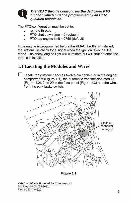
The VMAC throttle control uses the dedicated PTO function which must be programmed by an OEM qualified technician.
The PTO configuration must be set to:
• remote throttle • PTO shut down time = 0 (default) • PTO top engine limit = 2750 (default)
If the engine is programmed before the VMAC throttle is installed, the system will check for a signal when the ignition is on in PTO mode. The check engine light will illuminate but will shut off once the throttle is installed. 1.1 Locating the Modules and Wires
□ Locate the customer access twelve-pin connector in the engine compartment (Figure 1.1), the automatic transmission module (Figure 1.2), fuse 29 in the fuse panel (Figure 1.3) and the wires from the park brake switch.
Electrical connector on engine
Figure 1.1

VMAC – Vehicle Mounted Air Compressors Toll Free: 1-800-738-8622
Fax: 1-250-740-3201 6
Figure 1.2
29
Fuse panel Control box
Dash support
Figure 1.3

VMAC – Vehicle Mounted Air Compressors Toll Free: 1-800-738-8622 Fax: 1-250-740-3201
7
□ On trucks with hydraulic brakes, trace the black and tan wires from the park brake switch under the floor mat and under the dash near the data connector. Check the tan wire with an Ohm meter. It should show an open circuit when the park brake is released and no resistance when the park brake is applied.
□ On trucks with air brakes, check the tan wire at the pressure switch (Figure 1.4) with an Ohm meter. It should show an open circuit when the air brakes are released and no resistance when the air brakes are applied.
Pressure switch
Figure 1.4
□ Locate the blunt-cut wires under the dash and find the grey wire with a light blue stripe (Figure 1.5). Test it with a Voltmeter, it should show battery voltage with the ignition on and no Voltage with the ignition off.
□ On trucks with automatic transmissions, locate pin 41 on the transmission control module (Figure 1.6). Test the wire with the engine running (wheels blocked). It should read 12 Volts in PARK and NEUTRAL and 0 Volts in all gears.

VMAC – Vehicle Mounted Air Compressors Toll Free: 1-800-738-8622
Fax: 1-250-740-3201 8
Data-Linkconnector
Blunt cut wires
Figure 1.5
Pin 41
Wire side of the connector
Figure 1.6 1.2 Installing Components
□ Install the throttle controller under the dash beside the fuse panel. Secure it to the dash support with the tie straps (Figure 1.3).
□ If the truck has a manual transmission, cut the long blue wire from the throttle controller to about six inches and connect it to the short blue wire with the crimp connector.

VMAC – Vehicle Mounted Air Compressors Toll Free: 1-800-738-8622 Fax: 1-250-740-3201
9
□ Install the control box in a suitable location for easy access. You can mount it on the floor between the driver’s seat and the door so that it can be accessed from inside or outside the cab and route the wiring under the side door trim and under the dash. Trim the door sill so that wiring is not damaged and secure it with ties as necessary.
1.3 Connecting the Wiring
□ Disconnect the batteries.
□ Connect the white interface connector to the matching connector from the control box.
□ Connect the red wire from the interface connector to the red wire with the matching connector from the throttle control.
□ Remove fuse #29 from the fuse panel, insert the fuse tap and replace the fuse. Connect the red wire from throttle control to the tap. This connection must have battery voltage when the ignition switch is in both the start and run positions.
□ On trucks with hydraulic brakes, connect the black wire from the interface cable to the tan wire from the park brake switch.
□ Connect the red wire with the inline 10 Amp fuse from the white interface connector to the grey wire with the light blue stripe and the blunt-cut wire harness.
□ Route the following wires through an available access port just above the throttle pedal:
• black, orange and white wires from the throttle control • if the truck has an automatic transmission, the long blue
wire from the throttle controller • the cable with the black three pin connector from the
throttle controller • the cable with the green four pin connector from the
control box • the white wire with the bullet connector from the
interface connector • if equipped with air brakes, the black wire from the
interface cable

VMAC – Vehicle Mounted Air Compressors Toll Free: 1-800-738-8622
Fax: 1-250-740-3201 10
□ On air brake systems, splice the black wire to the tan wire with two red stripes at the air brake pressure switch on the firewall. Seal the splice with electrical tape.
□ Fasten the green throttle wire and the green interface cable wire to an exiting ground.
□ Leave the cables with the three and four pin connectors and the white wire with the bullet connector for connection to the compressor once it is installed.
□ Remove the protective cover from the customer access twelve-pin connector. Push out plastic pins at locations 1, 3 and 5. Insert the black wire connector into pin 1, the orange wire connector into pin 5 and the white wire connector into pin 3 (Figure 1.7). Push the connectors in securely so that they snap into place.
15
3
Black
Orange White
Figure 1.7
□ Splice the long blue wire to the wire from pin 41 at the transmission control module and seal the connection with tape.

VMAC – Vehicle Mounted Air Compressors Toll Free: 1-800-738-8622 Fax: 1-250-740-3201
11
Part 2: Preparing for Installation
□ Drain the cooling system.
□ Clean around the fuel filter, injection pump, turbocharger and air intake. Also clean the front of the engine to ensure that the bracket mounts properly.
□ Cut off the plastic locking rings from the lower radiator hose where it connects to the steel tube. Remove the steel tube and the rubber hose that connects to the engine spigot.
Be careful that you do not cut through the hose when you are cutting the rings, as the hoses will be reused.
□ Remove and discard the top expansion bottle hose.
□ Remove the six bolts holding the expansion bottle and move the expansion bottle out of the way. Replace and tighten the two OEM bolts in the front of the mounting bracket to the radiator cowl.
□ Remove the driver side intercooler tube.
Cover the opening on the engine and the opening on the turbocharger with plastic covers or tape to protect them from contaminants.
□ Remove the air cleaner from the left engine mounting bracket and discard the bolts.
□ Disconnect the turbocharger inlet elbow from the air cleaner. Lift the air cleaner off the left mount and pull it clear of the locating pins on the right-hand bracket.
□ Install the supplied spacer pad to the left engine mounting bracket using three socket head screws.
!

VMAC – Vehicle Mounted Air Compressors Toll Free: 1-800-738-8622
Fax: 1-250-740-3201 12
□ Install the spacer on the front locating pin on the right-hand bracket and install the air cleaner on the locating pins.
□ Fasten the air cleaner in place on the spacer block using the supplied bolts, then install and tighten the turbocharger inlet elbow on the right side of the air cleaner.
□ Remove any small brackets that locate hoses and wiring in the front upper engine sector.
□ Remove the OEM L-brackets securing the coolant expansion bottle hose to the cross-member under the engine.
□ Remove the two steel fuel lines from the fuel filter that connect to the cylinder head and to the injection pump. Cap the openings immediately to prevent contamination.
□ Remove the fuel filter assembly from the engine, including the bolt that clamps the oil fill tube. Store the fuel filter upright in a clean place to prevent fuel loss and contamination.
□ Loosen the two lower oil fill tube mounting bolts.
□ Clean excess paint and dirt from the engine where the fuel filter was mounted.
□ Remove the fan (left hand thread).
□ Clean the inside of the crankshaft pulley and remove all the bolts securing it to the harmonic balancer. Do not rotate the crankshaft pulley, as this may cause engine imbalance.
□ Place the crank pulley adaptor spacer on the rear of the VR crank pulley with the lip on the pulley sitting correctly in the recess of the adaptor and align the holes.
□ Position the pulley and adaptor on the front of the harmonic balancer with the dowel pins in two of the crankshaft holes.
□ Place the OEM crank pulley bolt ring plate on the front of the VR crank pulley, thread the supplied M10 x 100 mm bolts into the OEM crank pulley and torque to specifications.

VMAC – Vehicle Mounted Air Compressors Toll Free: 1-800-738-8622 Fax: 1-250-740-3201
13
Part 3: Installing the Cooler, Bracket and Compressor
Use Loctite on all bolts.
3.1 Installing the Oil Cooler
□ Install the OEM lower radiator hose (with HS40 and HS32 hose clamps) on the engine spigot but reverse the hose direction so that it faces to the rear of the truck. Leave the clamps loose.
□ Install the supplied piece of heater hose to the small spigot on the top of the cooler and tighten the clamp.
□ Place the cooler on the passenger side of the lower engine block (just in front of the oil filter) and fit the slot in the mounting plate over the engine lug.
□ As the cooler is maneuvered into place, push the hose spigot on the top of the cooler into the OEM reversed hose (Figure 2.1).
Make sure that the 1 inch coolant tank hose that runs along the engine cross-beam is in the cut-out notch of the cooler back plate.
□ Align the four mounting holes with the threaded holes in the engine. then install the four M14 x 30 mm bolts and torque to specifications.
□ Align the radiator hose to clear the engine frame cross beam bolts (Figure 3.1) and tighten the clamps.
Make sure that you provide sufficient clearance or cover the bolt ends so that the hose will not contact them. The hose will swell during engine operation.

VMAC – Vehicle Mounted Air Compressors Toll Free: 1-800-738-8622
Fax: 1-250-740-3201 14
Oil filter
Cooler
Lower hoseEngine lug
Enginespigot
1/2” hose from tank 1/2” hose from compressor
Protect the hose fromthe bolt ends
Figure 3.1
□ Install the supplied 90 degree rubber coolant hose between the radiator and the cooler, with the small end on the radiator and the large end on the cooler. Secure with hose clamps.
□ Locate the heater supply hose that connects between the heater core and the back of the thermostat housing.
□ Cut the hose 2 inches back from the connection at the thermostat housing and install the supplied T-connector.
□ Connect the hose from the cooler to the T-connector and secure all hoses with clamps.
VMAC – Vehicle Mounted Air Compressors Toll Free: 1-800-738-8622 Fax: 1-250-740-3201
15
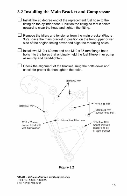
3.2 Installing the Main Bracket and Compressor
□ Install the 90 degree end of the replacement fuel hose to the fitting on the cylinder head. Position the fitting so that it points upward to clear the head and tighten the fitting.
□ Remove the idlers and tensioner from the main bracket (Figure 3.2). Place the main bracket in position on the front upper driver side of the engine timing cover and align the mounting holes.
□ Install two M10 x 60 mm and one M10 x 35 mm flange head bolts into the holes that originally held the fuel filter/primer pump assembly and hand-tighten.
□ Check the alignment of the bracket, snug the bolts down and check for proper fit, then tighten the bolts.
M10 x 60 mm
M10 x 35 mmM10 x 55 mm
OEM fuel filter mount bolt with spacer and oilfill tube bracket
M10 x 35 mm socket head bolt
M10 x 35 mm socket head boltwith flat washer
Mount fuel filter here
Figure 3.2

VMAC – Vehicle Mounted Air Compressors Toll Free: 1-800-738-8622
Fax: 1-250-740-3201 16
During tightening, make sure that alignment is correct and there are no gaps. Do not use the bolts to force gaps to close, check and correct the reason for the gap.
□ Install the fan spacer and the fan. Torque to specifications.
□ Install the VR belt tensioner, the three back idlers to the upper posts of the bracket and the ribbed idler to the lower post.
□ Remove the inlet valve from the compressor and immediately cover the opening on the compressor to prevent contamination.
□ Place the compressor in position on the main bracket, insert the four M8 x 110 mm socket head bolts through the holes in the compressor, thread them into the main bracket and torque to specifications.
□ Install the inlet valve and torque the socket head bolts to specifications.
3.3 Connecting the Hoses
□ Route the 1 inch, 1/4 inch and 5/16 inch hoses from the tank up into the engine compartment.
□ Connect the 1 inch hose to the matching fitting on the compressor and tighten the fitting.
□ Route the 1/2 hose from the tank up to and across the engine cross-member. Connect the 90 degree end to the rear fitting on the cooler (Figure 2.1)and tighten the fitting.
□ Connect the 90 degree end of the short 1/2 inch hose to the front oil cooler fitting and route the hose across the engine cross-member and up to the compressor. Connect it to the matching fitting on the compressor and tighten both fittings.
Make sure that none of the hoses will interfere with moving parts or contact hot objects. Secure them with ties or clamps. Protect them where they might rub.
VMAC – Vehicle Mounted Air Compressors Toll Free: 1-800-738-8622 Fax: 1-250-740-3201
17
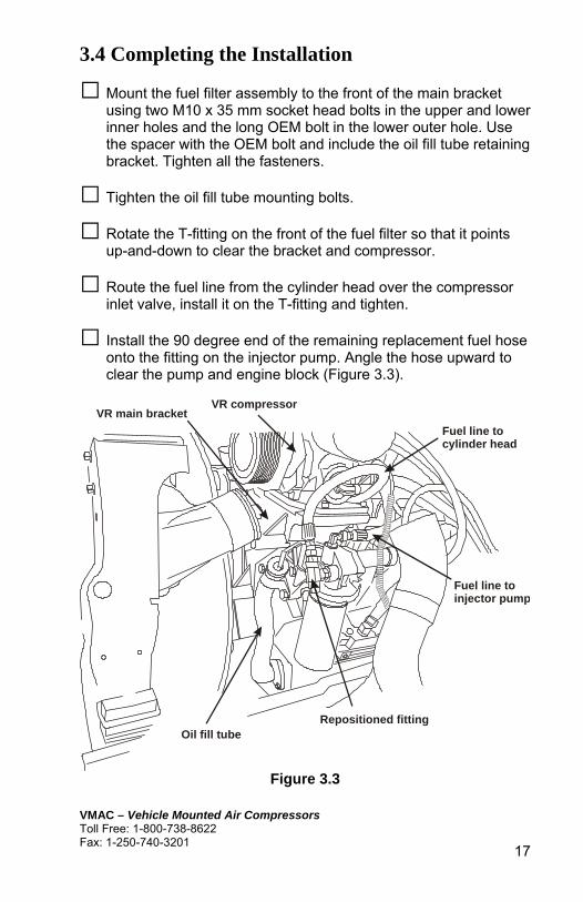
3.4 Completing the Installation
□ Mount the fuel filter assembly to the front of the main bracket using two M10 x 35 mm socket head bolts in the upper and lower inner holes and the long OEM bolt in the lower outer hole. Use the spacer with the OEM bolt and include the oil fill tube retaining bracket. Tighten all the fasteners.
□ Tighten the oil fill tube mounting bolts.
□ Rotate the T-fitting on the front of the fuel filter so that it points up-and-down to clear the bracket and compressor.
□ Route the fuel line from the cylinder head over the compressor inlet valve, install it on the T-fitting and tighten.
□ Install the 90 degree end of the remaining replacement fuel hose onto the fitting on the injector pump. Angle the hose upward to clear the pump and engine block (Figure 3.3).
VR compressor
Fuel line to cylinder head
Fuel line toinjector pump
Repositioned fitting
VR main bracket
Oil fill tube
Figure 3.3

VMAC – Vehicle Mounted Air Compressors Toll Free: 1-800-738-8622
Fax: 1-250-740-3201 18
□ Route the fuel line from the injector pump to the 90 degree fitting on the fuel filter and tighten the fitting on the fuel filter.
□ Operate the fuel primer pump until fuel fills the new line. If you do not clear the air in the hose, air will enter the fuel system and the engine will not start.
□ Install the intercooler tube and tighten the clamps.
□ Route the 5/16 inch hose from the tank up to the compressor, connect it to the matching fitting and tighten the fitting.
□ Route the 1/4 inch hose from the tank to the compressor, connect it to the matching fitting and tighten.
□ Install the supplied steel coolant pipes and flex hoses onto the lower hose, around the outside of the intercooler connection, over the top of the fan shroud and to the thermostat housing (Figure 3.4 - viewed from the front of the engine).
Radiator spigotuse OEM hose
Intercooler tube
Compressor
Thermostat housing
Supplied 90 degree hose and clamps
Supplied hoseand clamps
Figure 3.4

VMAC – Vehicle Mounted Air Compressors Toll Free: 1-800-738-8622 Fax: 1-250-740-3201
19
□ Adjust the tubes to provide clearance for the compressor clutch and secure with clamps.
□ Install the VR compressor belt (Figure 3.5).
Figure 3.5
□ Install the 1/2 inch aluminum block to the bottom coolant bottle mounting position on the radiator with two M8 x 30 mm bolts.
□ Install the coolant expansion bottle to the lower block bracket with the OEM bolts. Attach the hoses, with the hose in the groove on the main bracket and away from all moving parts.
□ Fit the upper extender bracket over the studs on the top mounting location. Also install the small L-bracket to the rear-most stud. Secure the top of the expansion bottle and the L-bracket with two M8 x 16 mm bolts and serrated nuts.

VMAC – Vehicle Mounted Air Compressors Toll Free: 1-800-738-8622
Fax: 1-250-740-3201 20
□ Fit a large insulated clip over the metal radiator hose and secure it to the L-bracket with an M8 x 25 mm bolt, nut and washer.
□ Fill the cooling system to manufacturer specifications.
□ Check all wiring harnesses, hoses and other items to make sure that they are secure and will not contact any moving parts.
3.5 Adding Oil to the System
Tighten all fittings before adding oil to the system.
□ Remove the fill plug from the air inlet control valve and pour oil into the oil fill hole on the inlet control valve using a funnel.
You must use the supplied VMAC compressor oil in this system. Failure to use this special oil will result in damage to the compressor and will void your warranty.
□ Turn the compressor clutch clockwise with a ratchet and a 1/2 inch socket using the hex head bolt at the centre of the compressor clutch during the fill process.
□ Allow 5 minutes for the oil to drain into the tank, check the level at the sight glass and continue adding oil until the level is correct.
Do not overfill the system, as this can flood the sight glass window and make the system appear empty.
□ Install the fill plug in the inlet control valve and tighten it securely.
!
!

VMAC – Vehicle Mounted Air Compressors Toll Free: 1-800-738-8622 Fax: 1-250-740-3201
21
Part 4: Installing the Tank and Hoses
4.1 Installing the Tank Use Loctite on all bolts.
□ Place the tank support brackets in position on the driver side of the frame, with the L-brackets on the inside of the frame, facing inward (Figure 4.1).
If the tank cannot be mounted on the driver side frame rail, it can be mounted on the passenger side, but will require a hose extender kit (see the appropriate section in General Information).
□ Remove the pinch bolts from the C-clamps, spread them slightly and fit them over the tank.
□ Install the pinch bolts and tighten them enough to hold the C-clamps in place but still permit movement.
□ Place the tank in position on the frame and thread the bolts through the C-clamps into the mounts, but do not tighten.
□ Adjust the tank so that the front of the tank is about 12 inches back from the cross-member. Rotate the tank so that the “UP” arrow points upward.
□ Tighten the C-clamps.
□ Install the 1/4 and 5/16 inch steel lines, complete with hoses, into the matching fittings on the back of the tank, but do not tighten the fittings.
□ Remove the two inner C-clamp bolts, place two double-tube insulated clamps over the tubes and fasten them in place along with the inside of the C-clamps (Figure 4.2).

VMAC – Vehicle Mounted Air Compressors Toll Free: 1-800-738-8622
Fax: 1-250-740-3201 22
6”
Cross-memberbolts
Fuel tank brackets
Figure 4.1
5/16" tube
1/4" tube
Insulated double tube clamp
5/16" bolt, washer and nut
Figure 4.2
□ Tighten all bolts
□ Tighten the steel tube fittings on the back of the tank 4.2 Connecting the Hoses
□ Connect the straight ends of the 1 inch and the longest 1/2 inch hose to the matching fittings on the front of the tank, but do not tighten the fittings.
□ Route the 1 inch, 5/16 inch and 1/4 inch hoses together along the frame rail to the front of the vehicle. Fasten them together with nylon ties and secure them to the OEM support brackets that are located at regular intervals along the frame (Figure 4.3).

VMAC – Vehicle Mounted Air Compressors Toll Free: 1-800-738-8622 Fax: 1-250-740-3201
23
□ Route the 1/2 inch hose from the tank along the frame to the engine cross-member, then over to the passenger side following the same route as the hose from the expansion bottle.
Select a route that will clear the exhaust and the turbocharger piping.
□ When all the hoses have been routed and secured, tighten the fittings at the tank.
OEM support brackets
Air lines
Figure 4.3

VMAC – Vehicle Mounted Air Compressors Toll Free: 1-800-738-8622
Fax: 1-250-740-3201 24
Part 5: Finishing the Installation
5.1 Before Starting the Engine Checklist Make sure that the following have been completed:
□ Check the coolant.
□ Check the compressor oil level.
□ Do a final inspection to make sure that everything has been connected and tightened.
□ Perform a final belt alignment check.
□ Check all wiring for security and protection.
□ Switch the ignition “ON”. The green LED and red LED should flash and the display should be on. The throttle control green LED should also be flashing.
□ Push the “ON” button on the control box. The green LED on the control box and the green LED on the throttle control should be illuminated.
□ Push the “OFF” button on the control box. The green LED on the control box should be off and the green LED on the throttle control should be flashing.
5.2 After Starting the Engine Checklist Make sure that the following have been completed:
□ Place a test tool in the tank outlet fitting and close the ball valve.
□ Start the engine and let it reach operating temperature.
□ Push the “ON” button on the control box. The green LED on the control box should illuminate and engine speed should increase to 2,000 rpm, then drop back down to 900 rpm in about five seconds.

VMAC – Vehicle Mounted Air Compressors Toll Free: 1-800-738-8622 Fax: 1-250-740-3201
25
□ Open the ball valve so that the pressure gauge shows 100 psi. Engine speed should increase to 1,800 – 2,000 rpm.
□ Close the ball valve. Engine speed should decrease to 900 rpm.
□ With the compressor operating and the ball valve closed, apply the foot brake and release the park brake. The compressor clutch should disengage. Wait 20 seconds, apply the park brake and switch the compressor “ON”. The compressor should operate as before. Switch the compressor “OFF”.
□ For trucks with automatic transmissions, block the wheels and apply the brakes. Shift the transmission into drive and switch the compressor “ON”. The compressor clutch should engage but the engine speed should not increase. Switch the compressor “OFF”.
□ Wait 20 seconds between tests and repeat in all forward and reverse gear positions.
□ Road test the truck for approximately 14 miles (20 km)
□ Watch the underhood operation to make sure that belts rotate properly and nothing is rubbing or contacting hot parts.
□ Check all components once the engine is turned off and the system has cooled
□ Check the coolant after the engine reaches operating temperature.
□ Check the compressor oil level after the engine has been shut down and the oil level has had time to stabilize.
If the truck fails the safety tests, check the wiring to make sure that all the connections are correct. If you require additional assistance, contact your local VMAC dealer. Call 1-800-738-8622 or 250-740-3200. !

VMAC – Vehicle Mounted Air Compressors Toll Free: 1-800-738-8622
Fax: 1-250-740-3201 26
5.3 Setup, Performance Testing and Adjustments This system has been adjusted at the factory for general operation. If your tests indicate that adjustment is necessary, refer to the owner’s manual for specific instructions on how to adjust the system.
You can test the system operation using the tools that will be operated by the system or you can test operations sing an orifice in the outlet to simulate tool use (Figure 5.1).
Figure 5.1
1. Install the test tool in the tank outlet fitting.
2. Make sure that the ball valve is closed.
3. Place the manual transmission in neutral or the automatic transmission in park and fully apply the park brake.
4. Allow the engine to run until it is at operating temperature.
5. Operate the air compressor system until the oil is warm.
6. Observe the pressure gauge. Pressure should be approximately 150 psi.
7. Open the ball valve on the test tool and observe the engine tachometer. Engine speed should increase to about 1,800 - 2,200 RPM.
8. Close the air valve slowly to allow the system pressure to rise.
9. Once the system pressure is at maximum, slowly open the ball valve on the test tool until the pressure on the gauge begins to drop. Engine speed should start to ramp-up when air pressure drops to approximately 140 PSI.

VMAC – Vehicle Mounted Air Compressors Toll Free: 1-800-738-8622 Fax: 1-250-740-3201
27
5.4 System Identification and Warnings The System Identification Number Plate must be attached to the truck at the time of installation (Figure 5.2). This plate provides information which allows VMAC to assist in customer inquiries and the ordering of parts. Mark and drill two 7/64 inch holes, then secure the plate with self-tapping screws.
Install ID plate here
Driver’s door
Firewall
Figure 5.2
As part of the installation process, ensure that the safety and operational instruction decal is affixed in an obvious location so that it can be seen by truck operators (Figure 5.3).
Daily Pre-Start Check Start Up Procedure Shutdown Procedure
This Vehicle is Equipped with a VMAC Air Compressor System
1. Check Oil Level in Tank2. Check Drive Belt3. Check for Leaks
1. Allow engine to idle for 1 minute2. Turn OFF compressor3. Wait for system to discharge for 1 minute before restarting
1. Ensure Compressor is OFF2. Ensure discharge valve is CLOSED3. Ensure air system is discharged4. Place vehicle in Neutral or Park and engage vehicle safety features - park brake5. Start engine and bring up to operating temperature6. Turn ON compressor
For Technical Support/Parts contact your VMAC DealerTo locate your nearest dealer call 1-800-738-8622 (250-740-3200)
OPERATING INSTRUCTIONS
Always allow system pressure to discharge before restartingWARNING!
Figure 5.3
VMAC – Vehicle Mounted Air Compressors Toll Free: 1-800-738-8622
Fax: 1-250-740-3201 28
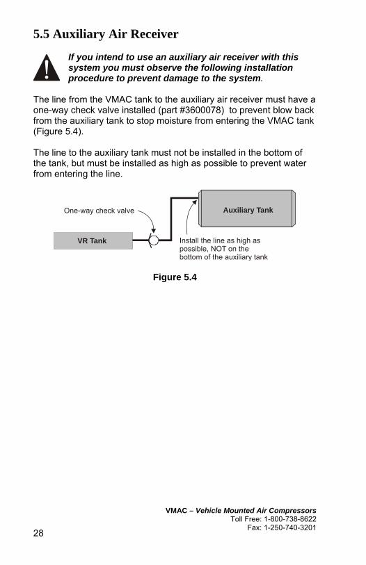
5.5 Auxiliary Air Receiver
If you intend to use an auxiliary air receiver with this system you must observe the following installation procedure to prevent damage to the system.
The line from the VMAC tank to the auxiliary air receiver must have a one-way check valve installed (part #3600078) to prevent blow back from the auxiliary tank to stop moisture from entering the VMAC tank (Figure 5.4). The line to the auxiliary tank must not be installed in the bottom of the tank, but must be installed as high as possible to prevent water from entering the line.
Install the line as high as possible, NOT on the bottom of the auxiliary tank
VR Tank
One-way check valve Auxiliary Tank
Figure 5.4
!

VMAC – Vehicle Mounted Air Compressors Toll Free: 1-800-738-8622 Fax: 1-250-740-3201
29
Accessory Products from VMAC The following accessory products for your VR compressor system are available from VMAC. For more information or to order these products, call 1-800-738-8622.
Eliminator Aftercooler Removes up to 80% of moisture from compressed air. Quick installation, automatic drain and compact design
Filter Regulator Lubricator Removes lubricants, water and dirt from the air stream. Adds atomized tool oil to lubricate tools. Reduces pressure for longer tool life.
Hose Reel Secure, compact, retractable hose storage in a sturdy reel.
Air Receiver Tank Thirty-five gallon capacity in a compact tank, complete with fittings and a gauge.
DE-ICING HEATER
De-icer Kit Insulated rope heater prevents freezing of lines and regulator.
Service Kits Using OEM service products will extend the life of your system. Includes oil, filters, seals and O-rings. 200 hour and 400 hour service interval kits are available