Embed Size (px)
Citation preview

Annunciator Control System
ACS SeriesInstallation Manual
Document 158427/23/2002 Rev: K
PN 15842:K ECN 02-266
www.PDF-Zoo.com

2 PN 15842:K 7/23/20022 PN 15842:K 7/23/2002
Fire Alarm System LimitationsWhile a fire alarm system may lower insurance rates, it is not a substitute for fire insurance!An automatic fire alarm system—typically made up of smoke detectors, heat detectors, manual pull stations, audible warning devices, and a fire alarm control with remote notification capability—can provide early warning of a developing fire. Such a system, however, does not assure protection against property damage or loss of life resulting from a fire. The Manufacturer recommends that smoke and/or heat detectors be located throughout a protected premise fol-lowing the recommendations of the current edition of the National Fire Protection Association Standard 72 (NFPA 72), manufacturer's recommendations, State and local codes, and the recommendations contained in the Guide for Proper Use of System Smoke Detectors, which is made available at no charge to all installing dealers. A study by the Federal Emergency Management Agency (an agency of the United States government) indicated that smoke detectors may not go off in as many as 35% of all fires. While fire alarm systems are designed to pro-vide early warning against fire, they do not guarantee warning or protection against fire. A fire alarm system may not provide timely or adequate warning, or simply may not function, for a variety of reasons: Smoke detectors may not sense fire where smoke can-not reach the detectors such as in chimneys, in or behind walls, on roofs, or on the other side of closed doors. Smoke detectors also may not sense a fire on another level or floor of a building. A second-floor detector, for example, may not sense a first-floor or basement fire. Particles of combustion or “smoke” from a develop-ing fire may not reach the sensing chambers of smoke detectors because:• Barriers such as closed or partially closed doors,
walls, or chimneys may inhibit particle or smoke flow. • Smoke particles may become “cold,” stratify, and not
reach the ceiling or upper walls where detectors are located.
• Smoke particles may be blown away from detectors by air outlets.
• Smoke particles may be drawn into air returns before reaching the detector.
The amount of “smoke” present may be insufficient to alarm smoke detectors. Smoke detectors are designed to alarm at various levels of smoke density. If such den-sity levels are not created by a developing fire at the location of detectors, the detectors will not go into alarm. Smoke detectors, even when working properly, have sensing limitations. Detectors that have photoelectronic sensing chambers tend to detect smoldering fires better than flaming fires, which have little visible smoke. Detec-tors that have ionizing-type sensing chambers tend to detect fast-flaming fires better than smoldering fires. Because fires develop in different ways and are often unpredictable in their growth, neither type of detector is necessarily best and a given type of detector may not provide adequate warning of a fire. Smoke detectors cannot be expected to provide ade-quate warning of fires caused by arson, children playing with matches (especially in bedrooms), smoking in bed, and violent explosions (caused by escaping gas, improper storage of flammable materials, etc.).
Heat detectors do not sense particles of combustion and alarm only when heat on their sensors increases at a predetermined rate or reaches a predetermined level. Rate-of-rise heat detectors may be subject to reduced sensitivity over time. For this reason, the rate-of-rise fea-ture of each detector should be tested at least once per year by a qualified fire protection specialist. Heat detec-tors are designed to protect property, not life. IMPORTANT! Smoke detectors must be installed in the same room as the control panel and in rooms used by the system for the connection of alarm transmission wir-ing, communications, signaling, and/or power. If detec-tors are not so located, a developing fire may damage the alarm system, crippling its ability to report a fire. Audible warning devices such as bells may not alert people if these devices are located on the other side of closed or partly open doors or are located on another floor of a building. Any warning device may fail to alert people with a disability or those who have recently con-sumed drugs, alcohol or medication. Please note that:• Strobes can, under certain circumstances, cause sei-
zures in people with conditions such as epilepsy. • Studies have shown that certain people, even when
they hear a fire alarm signal, do not respond or com-prehend the meaning of the signal. It is the property owner's responsibility to conduct fire drills and other training exercise to make people aware of fire alarm signals and instruct them on the proper reaction to alarm signals.
• In rare instances, the sounding of a warning device can cause temporary or permanent hearing loss.
A fire alarm system will not operate without any electri-cal power. If AC power fails, the system will operate from standby batteries only for a specified time and only if the batteries have been properly maintained and replaced regularly. Equipment used in the system may not be technically compatible with the control. It is essential to use only equipment listed for service with your control panel. Telephone lines needed to transmit alarm signals from a premise to a central monitoring station may be out of service or temporarily disabled. For added protection against telephone line failure, backup radio transmission systems are recommended. The most common cause of fire alarm malfunction is inadequate maintenance. To keep the entire fire alarm system in excellent working order, ongoing maintenance is required per the manufacturer's recommendations, and UL and NFPA standards. At a minimum, the require-ments of Chapter 7 of NFPA 72 shall be followed. Envi-ronments with large amounts of dust, dirt or high air velocity require more frequent maintenance. A mainte-nance agreement should be arranged through the local manufacturer's representative. Maintenance should be scheduled monthly or as required by National and/or local fire codes and should be performed by authorized professional fire alarm installers only. Adequate written records of all inspections should be kept.
Precau-S-4-2002.fm
www.PDF-Zoo.com

PN 15842:K 7/23/2002 3
Installation PrecautionsAdherence to the following will aid in problem-free installation with long-term reliability:WARNING - Several different sources of power can be connected to the fire alarm control panel. Discon-nect all sources of power before servicing. Control unit and associated equipment may be damaged by remov-ing and/or inserting cards, modules, or interconnecting cables while the unit is energized. Do not attempt to install, service, or operate this unit until this manual is read and understood. CAUTION - System Reacceptance Test after Soft-ware Changes. To ensure proper system operation, this product must be tested in accordance with NFPA 72 Chapter 7 after any programming operation or change in site-specific software. Reacceptance testing is required after any change, addition or deletion of system compo-nents, or after any modification, repair or adjustment to system hardware or wiring. All components, circuits, system operations, or software functions known to be affected by a change must be 100% tested. In addition, to ensure that other operations are not inadvertently affected, at least 10% of initiating devices that are not directly affected by the change, up to a maximum of 50 devices, must also be tested and proper system operation verified. This system meets NFPA requirements for operation at 0-49° C/32-120° F and at a relative humidity of 85% RH - 93% per ULC - (non-condensing) at 30° C/86° F. How-ever, the useful life of the system's standby batteries and the electronic components may be adversely affected by extreme temperature ranges and humidity. Therefore, it is recommended that this system and all peripherals be installed in an environment with a nominal room temper-ature of 15-27° C/60-80° F. Verify that wire sizes are adequate for all initiating and indicating device loops. Most devices cannot tolerate more than a 10% I.R. drop from the specified device volt-age.
Like all solid state electronic devices, this system may operate erratically or can be damaged when sub-jected to lightning-induced transients. Although no sys-tem is completely immune from lightning transients and interferences, proper grounding will reduce susceptibility. Overhead or outside aerial wiring is not recommended, due to an increased susceptibility to nearby lightning strikes. Consult with the Technical Services Department if any problems are anticipated or encountered. Disconnect AC power and batteries prior to removing or inserting circuit boards. Failure to do so can damage circuits. Remove all electronic assemblies prior to any drilling, filing, reaming, or punching of the enclosure. When pos-sible, make all cable entries from the sides or rear. Before making modifications, verify that they will not interfere with battery, transformer, and printed circuit board location. Do not tighten screw terminals more than 9 in-lbs. Over-tightening may damage threads, resulting in reduced terminal contact pressure and difficulty with screw terminal removal. Though designed to last many years, system compo-nents can fail at any time. This system contains static-sensitive components. Always ground yourself with a proper wrist strap before handling any circuits so that static charges are removed from the body. Use static-suppressive packaging to protect electronic assemblies removed from the unit. Follow the instructions in the installation, operating, and programming manuals. These instructions must be followed to avoid damage to the control panel and asso-ciated equipment. FACP operation and reliability depend upon proper installation by authorized personnel.
Precau-S-4-2002.fm
FCC WarningWARNING: This equipment generates, uses, and can radiate radio frequency energy and if not installed and used in accordance with the instruc-tion manual, may cause interference to radio com-munications. It has been tested and found to comply with the limits for class A computing device pursuant to Subpart B of Part 15 of FCC Rules, which is designed to provide reasonable protection against such interference when operated in a com-mercial environment. Operation of this equipment in a residential area is likely to cause interference, in which case the user will be required to correct the interference at his own expense.
Canadian RequirementsThis digital apparatus does not exceed the Class A limits for radiation noise emissions from digital apparatus set out in the Radio Interference Regu-lations of the Canadian Department of Communi-cations. Le present appareil numerique n'emet pas de bruits radioelectriques depassant les limites appli-cables aux appareils numeriques de la classe A prescrites dans le Reglement sur le brouillage radi-oelectrique edicte par le ministere des Communi-cations du Canada.
Acclimate Plus™, HARSH™, NOTI•FIRE•NET™, ONYX™, and VeriFire™ are trademarks, and FlashScan®and VIEW® are registered trademarks of NOTIFIER. NION™ and UniNet™ are trademarks of NIS. NIS™ andNotifier Integrated Systems™ are trademarks and NOTIFIER® is a registered trademark of Fire•Lite Alarms, Inc.Echelon® is a registered trademark and LonWorks™ is a trademark of Echelon Corporation. ARCNET® is aregistered trademark of Datapoint Corporation. Microsoft® and Windows® are registered trademarks of theMicrosoft Corporation. LEXAN® is a registered trademark of GE Plastics, a subsidiary of General ElectricCompany.
www.PDF-Zoo.com

4 PN 15842:K 7/23/2002
Table of ContentsTable of Contents ........................................................................................... 41 Product Overview ......................................................................................8
General .....................................................................................................8Panel Compatibility: .........................................................................9ACM-24AT, ACM-48A, AEM-24AT, and AEM-48A ....................9ACM-16AT, ACM-32A, Expanders, and Variations ....................10
Related Documentation ..........................................................................102 Product Overview ....................................................................................12
ACM-24AT and AEM-24AT ..................................................................12ACM-48A and AEM-48A ......................................................................12ACM-16AT Series ..................................................................................13
Control Modules ..............................................................................13Expander Modules ..........................................................................13
ACM-32A Series ....................................................................................14Control Modules ..............................................................................14Expander Modules ..........................................................................14
Cabinet & Panel Hardware .....................................................................15Surface-Mount Backboxes .............................................................15Flush-mount Backboxes ..................................................................15Semi-flush-mount Backboxes .........................................................16Additional Hardware .......................................................................18
3 Design Considerations .............................................................................20Limits .....................................................................................................20Wire Runs ...............................................................................................20EIA-485 Wiring Specifications ..............................................................20Receive/Transmit and Receive Only Configuration ..............................21Cabinet Mounting of Annunciators ........................................................22Annunciator Power Requirements & Electrical Ratings ........................23
4 Installation, Configuration, and Programming ....................................25Installation Checklist ..............................................................................25Connections and Switches ......................................................................26Mount the Cabinet or Backbox ..............................................................28Mount Annunciators and Expanders ......................................................28EIA-485 Circuit Connections .................................................................30Shielding the EIA-485 Circuit ................................................................31End of Line Resistor for EIA-485 Circuit ..............................................31Earth Ground ..........................................................................................32Main Power Supply Connections ...........................................................32Labeling Annunciators & Expanders .....................................................34Connecting Annunciator Key Switch and Phone Jack ...........................35Setting Address and DIP Switches: ACM-24AT, ACM-48A ................36
DIP Switch Summary: ACM-24AT, ACM-48A ............................36Addressing ACM-24AT and ACM-48A .........................................37
www.PDF-Zoo.com
PN 15842:K 7/23/2002 5
Configuring Number of Expander Modules ...................................37Speaker Control Mode ...................................................................38
Setting Address and DIP Switches: ACM-16AT, ACM-32A ................40DIP Switch Summary: ACM-16AT, ACM-32A ............................40Addressing ACM-16AT and ACM-32A .........................................40Configuring Number of Expander Modules ...................................41
Supervising Devices with ACM-16AT, ACM-32A ...............................41Programming the Control Panel and Annunciators ................................42
Selecting LED Colors: ACM-24AT and AEM-24AT ....................42Selecting LED Colors: ACM-48A & AEM-48A ............................42
Testing the Annunciators ........................................................................425 LED and Keypad-Switch Functions ......................................................43
ACM-24AT, ACM-48A, and Expanders ...............................................43Acknowledge/Lamp Test Switch ....................................................43On-line LED ....................................................................................43System Trouble LED ......................................................................44Control Switch ................................................................................44Point-Active LED ...........................................................................44Trouble LED ...................................................................................44
ACM-16AT, ACM-32A, and Expanders ................................................45ACM-16AT .....................................................................................45AEM-16AT .....................................................................................46ACM-32A .......................................................................................47AEM-32A ........................................................................................48
Appendix A: AFP-100 Systems .................................................................. 49Capabilities ............................................................................................. 49Connecting the EIA-485 Circuit ............................................................ 49Providing Power to Annunciators .......................................................... 49Configuring Annunciators for AFP-100 ................................................ 50
Appendix B: AFP-200 Systems .................................................................. 51Capabilities ............................................................................................. 51Connecting the EIA-485 Circuit ............................................................ 51Providing Power to Annunciators .......................................................... 51Configuring Annunciators for the AFP-200 ........................................... 52
Appendix C: AFP-300/AFP-400 ................................................................. 53Capabilities ............................................................................................. 53Connecting the EIA-485 Circuit ............................................................ 53Providing Power to Annunciators .......................................................... 53Configuring Annunciators for the AFP-300/AFP-400 ........................... 54System and Point Annunciation ............................................................. 55
Appendix D: AFC-600 Systems .................................................................. 56Capabilities ............................................................................................. 56Connecting the EIA-485 Circuit ............................................................ 56Providing Power to Annunciators .......................................................... 56
www.PDF-Zoo.com
6 PN 15842:K 7/23/2002
Configuring Annunciators for the AFC-600 .......................................... 57System and Point Annunciation ............................................................. 57
Appendix E: AM2020/AFP1010 Systems .................................................. 59Capabilities ............................................................................................. 59Connecting the EIA-485 Circuit ............................................................ 59Providing Power to Annunciators .......................................................... 60Programming the AM2020/AFP1010 for Remote Annunciation .......... 61Configuring Annunciators for AM2020/AFP1010 ................................ 62Configurations for Specific Applications ............................................... 63
Common System Annunciation ...................................................... 63Speaker and Telephone Mode ......................................................... 64Manual Override ............................................................................. 64
ACS Program Mapping .......................................................................... 66Appendix F: NFS-640 Systems ................................................................... 67
Capabilities ............................................................................................. 67Connecting the EIA-485 Circuit ............................................................ 67Providing Power to Annunciators .......................................................... 68Configuring Annunciators for the NFS-640 ........................................... 69System and Point Annunciation ............................................................. 70
Appendix G: System 500 Systems: ACM-16AT and ACM-32A Only .... 71Capabilities ............................................................................................. 71Connecting EIA-485 Circuit .................................................................. 71Providing Power to Annunciators .......................................................... 72Configuring the ACS for System 500 .................................................... 73ACS Program Mapping .......................................................................... 74
Appendix H: System 5000 Systems: ACM-16AT and ACM-32A Only .. 76Capabilities ............................................................................................. 76Connecting the EIA-485 Circuit ............................................................ 76Providing Power to Annunciators .......................................................... 77Installing Modules in the System ........................................................... 78Configuring the ACS for System 5000 .................................................. 79ACS Program Mapping .......................................................................... 80AIM-200 Point Annunciation ................................................................. 81
Appendix I: Combination Fire Alarm/Burglary Systems ....................... 83Appendix J: NCA Systems ......................................................................... 84
Capabilities ............................................................................................ 84Connecting the EIA-485 Circuit ............................................................ 84Providing Power to Annunciators .......................................................... 84Programming the NCA for Remote Annunciation ................................. 85Configuring Annunciators for the NCA ................................................. 86
Appendix K: NFS-3030 Systems ............................................................... 87Capabilities ............................................................................................. 87Connecting the EIA-485 Circuit ........................................................... 87
www.PDF-Zoo.com

PN 15842:K 7/23/2002 7
Providing Power to Annunciators ......................................................... 88Programming the NFS-3030 for Remote Annunciation ........................ 88Configuring Annunciators for NFS-3030 .............................................. 89Configurations for Specific Applications ............................................... 90
Common System Annunciation ...................................................... 90Speaker and Telephone Mode ......................................................... 91Manual Override ............................................................................. 91
ACS Program Mapping ......................................................................... 93Index ............................................................................................................. 95
www.PDF-Zoo.com

Product Overview
8 PN 15842:K 7/23/2002
Section 1 Product OverviewAbout This Manual. The core of this manual provides instructions for connecting an ACS series annunciator to various fire alarm control panels (FACPs). Each appendix contains instructions that are unique to a particular control panel. Section 1.2 “Related Documentation” lists part numbers for manuals of compatible equipment such as control panels.
This manual provides instructions for two sets of ACS series annunciators. Both sets can be used in the same fire alarm system. There are four basic controller modules, each with its own expander module:
• ACM-24AT, ACM-48A, AEM-24AT, and AEM-48A: Up to 96 points can occupy the same address, subject to the limits of the control panel.
• ACM-16AT, ACM-32A, AEM-16AT, AEM-32A, and multi-color variations (Section 2 “Product Overview” lists similarly numbered models that provide different LED colors): Up to 64 points can occupy the same address, subject to the limits of the control panel.
In this manual, when the two varieties of ACS annunciator differ, the ACM-24AT/ACM-48A annunciators are discussed first.
1.1 GeneralACS annunciators provide Notifier fire alarm control panels or network displays with remote serially connected annunciators. Arrays of LEDs indicate, at a remote location, the status of circuits within the system. Individual fire alarm control panels offer different methods of identifying annunciator points.
Common system functions such as signal silence, system reset, and local annunciation controls (local acknowledge and lamp test) are controlled through switches on the annunciator’s keypad.
Communication between the control panels or network displays and these annunciators is accomplished over a power-limited, two-wire serial interface employing an EIA-485 communication standard. Power for these annunciators is provided via a separate power-limited power loop from the control panel which is inherently supervised by these annunciators (loss of power results in an annunciator communication failure at the control panel). These annunciators can also be powered from a power-limited and regulated remote power supply listed for fire-protective signalling use.
The National Standard of Canada (CAN/ULC-S527) requires that a dedicated display use yellow visual indicators to indicate the status of supervisory inputs. The annunciators listed below are intended to be used for Canadian Supervisory Service in conjunction with AFP-200, AFP-400, S500, S2500, and S5000 control units (subject to annunciator-panel compatibility):
• ACM-24AT/ACM-48A and expanders: These modules provide programmable colors (red/green/yellow).
• ACM-16AT/ACM-32A and expanders: Modules in the -16/-32 “Y” series have been designed with yellow LEDs; other colors are also available (see Section 2.3 and Section 2.4).
www.PDF-Zoo.com

Product Overview
PN 15842:K 7/23/2002 9
The ACM-32A, AEM-32A, ACM-16AT, and AEM-16AT annunciators can not be employed for ULC Supervisory Service. See Canadian Requirements for Supervisory Signal in Notifier Document 50056.
1.1.1 Panel Compatibility*:
1.1.2 ACM-24AT, ACM-48A, AEM-24AT, and AEM-48AThese annunciators provide Notifier fire alarm control panels with up to 32 remote serially connected annunciators each with a capacity of up to 96 points (subject to the limits of your control panel), for a total maximum capacity of 3,072 points. Individual fire alarm control panels offer different methods of identifying annunciator points:
• NFS-3030. Annunciator points are completely programmable and can be employed to annunciate and manually control common system, voice or telephone circuits. (Note: User-defined points can be defined by using VeriFire™ software; see your control panel manual.*)
• AM2020, AFP1010. Annunciator points are completely programmable and can be employed to annunciate and manually control common system, voice or telephone circuits.
• NFS-640, AFC-600. Annunciator points are programmable by group or by point. (Note: User-defined points can be defined by using VeriFire™ software; see your control panel manual.*)
• AFP-100, AFP-200, AFP-300, AFP-400. Annunciator points are programmable by group. (Note: User-defined points can be defined for AFP-300/AFP-400 systems by using VeriFire™ software; see your control panel manual.*)
The Network Control Annunciator (NCA) and Intelligent Network Annunciator (INA) can employ these annunciators on the EIA-485 interface. Refer to the NCA and INA manuals* for further details.
* Section 1.2 “Related Documentation” lists part numbers for manuals of compatible equipment such as control panels.
ACM-24AT, ACM-48A, AEM-24AT, and AEM-48A.• NFS-3030 (96 points)• AM2020/AFP1010 (64 points)• NFS-640 (64 points)• AFC-600 (64 points)• AFP-100 (64 points)• AFP-200 (64 points)• AFP-300/AFP-400 (64 points)• NCA Network Control Annunciator
(96 points)• INA Intelligent Network
Annunciator (64 points)
ACM-16AT, ACM-32A, AEM-16AT, AEM-32A, and color variations.• NFS-3030 (64 points)• AM2020/AFP1010 (64 points)• NFS-640 (64 points)• AFC-600 (64 points)• AFP-100 (64 points)• AFP-200 (64 points)• AFP-300/AFP-400 (64 points)• NCA (64 points)• INA (64 points)• System 500, System 5000,
System 2500 (64 points)
www.PDF-Zoo.com
Product Overview
10 PN 15842:K 7/23/2002
1.1.3 ACM-16AT, ACM-32A, Expanders, and Variations The Annunciator Control System (ACS) series provides Notifier fire alarm control panels* with up to 32 remote serially connected annunciators, each with a capacity of 64 points, for a total capacity of 2048 points. There are two basic controller modules, each with its own expander module. Individual fire alarm control panels* offer different methods of identifying annunciator points:
• NFS-3030. Annunciator points are completely programmable and can be employed to annunciate and manually control common system, voice or telephone circuits. (Note: User-defined points can be defined by using VeriFire™ software; see your control panel manual.*)
• NFS-640, AFC-600. Annunciator points are programmable by group or by point. (Note: User-defined points can be defined by using VeriFire™ software; see your control panel manual.)
• AM2020, AFP1010. Annunciator points are completely programmable and can be employed to annunciate and manually control common system, voice or telephone circuits.
• AFP-100, AFP-200, AFP-300, AFP-400. Annunciator points are programmable by group. (Note: User-defined points can be defined for AFP-300/AFP-400 systems by using VeriFire™ software; see your control panel manual.*)
• System 5000, System 2500, System 500. Annunciator points directly follow the circuit arrangement of modules installed in the cabinet.
The Network Control Annunciator (NCA) and Intelligent Network Annunciator (INA) can employ these annunciators on the EIA-485 interface. Refer to the NCA and INA manuals* for further details.
1.2 Related DocumentationThe table below provides a list of document sources (manuals) containing additional information regarding the fire alarm control panels and components that ACS annunciators can be connected to. The NOTIFIER document (DOC-NOT) chart provides the current document revision.
* Section 1.2 “Related Documentation” lists part numbers for manuals of compatible equipment such as control panels.
Continued on next page...
www.PDF-Zoo.com

Product Overview
PN 15842:K 7/23/2002 11
Systems that support ACS modulesNFS-3030
Installation ........................................51330Operation..........................................51344Programming ....................................51345
NFS-640 Installation ........................................51332Operation..........................................51334Programming ....................................51333
AFC-600 Installation ........................................51031Operation..........................................51033Programming ....................................51032
AFP-100.................................................51010AFP-200.................................................15511AFP-300/AFP-400
Installation ........................................50253Operation..........................................50260Programming ....................................50259
XPIQ ......................................................51013NCA Network Control Annunciator ........51482INA Intelligent Network Annunciator ......15092System 500 ............................................15019System 5000
Installation ........................................15583Operation..........................................15581Programming ....................................15584AIM-200 Installation Manual .............15949
System 2500 ..........................................15969NetworkingNoti•Fire•Net Manual .............................50257NCM-W/F Installation Document ...........51533Off-line Programming UtilityVeriFire™ Tools on-line help file..VeriFire-TCD VeriFire™ Medium Systems
on-line help file ........................VeriFire-CDVeriFire-1020 ........................................50529
Compatible DevicesDevice Compatibility Document .............15378Other ACS DevicesAnnunciator Fixed Module .....................15048ACM-8R Annunciator Control Module....15342LCD-80 Manual......................................15037LCD-80TM Manual.................................51082LDM Series Lamp Driver Annunciator ...15885NIB-96 Network Interface Board ...........15666RPT-485W/RPT-485WF
Installation Manual............................15640SCS-8 Installation Manual .....................15712TM-4 Installation Manual........................51490UDACT Installation Manual....................50050UZC-256
Installation .......................................15216Programming ...................................15976
Power Supplies & Battery ChargersACPS-2406 Installation Manual .............51304AMPS-24 Installation Manual.................51907APS-6R Instruction Manual....................50702CHG-120 Battery Charger Manual.........50641FCPS-24 Field Charger/Power Supply ..50059Cabinets & Chassis CAB-3/CAB-4 Series Installation
Document .........................................15330BMP-1 Blank Module Dress Plate
Installation Document ....................... 51119Canadian RegulationsCanadian Requirements for
Supervisory Signal............................50056
Table 1-1 Related Documentation
www.PDF-Zoo.com
Product Overview
12 PN 15842:K 7/23/2002
Section 2 Product OverviewThis section is intended as a basic inventory of components that can be used in an ACS system. For system design considerations, see Section 3. For installation, configuration and programming instructions, see Section 4. For LED and Switch functions instructions, see Section 5.
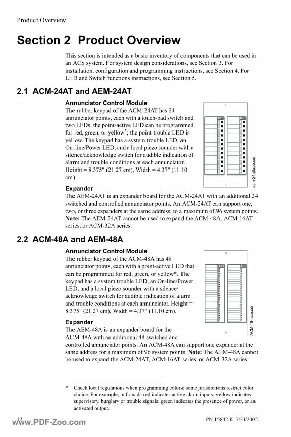
2.1 ACM-24AT and AEM-24ATAnnunciator Control ModuleThe rubber keypad of the ACM-24AT has 24 annunciator points, each with a touch-pad switch and two LEDs: the point-active LED can be programmed for red, green, or yellow*; the point-trouble LED is yellow. The keypad has a system trouble LED, an On-line/Power LED, and a local piezo sounder with a silence/acknowledge switch for audible indication of alarm and trouble conditions at each annunciator. Height = 8.375" (21.27 cm), Width = 4.37" (11.10 cm).
ExpanderThe AEM-24AT is an expander board for the ACM-24AT with an additional 24 switched and controlled annunciator points. An ACM-24AT can support one, two, or three expanders at the same address, to a maximum of 96 system points. Note: The AEM-24AT cannot be used to expand the ACM-48A, ACM-16AT series, or ACM-32A series.
2.2 ACM-48A and AEM-48AAnnunciator Control ModuleThe rubber keypad of the ACM-48A has 48 annunciator points, each with a point-active LED that can be programmed for red, green, or yellow*. The keypad has a system trouble LED, an On-line/Power LED, and a local piezo sounder with a silence/acknowledge switch for audible indication of alarm and trouble conditions at each annunciator. Height = 8.375" (21.27 cm), Width = 4.37" (11.10 cm).
ExpanderThe AEM-48A is an expander board for the ACM-48A with an additional 48 switched and controlled annunciator points. An ACM-48A can support one expander at the same address for a maximum of 96 system points. Note: The AEM-48A cannot be used to expand the ACM-24AT, ACM-16AT series, or ACM-32A series.
* Check local regulations when programming colors; some jurisdictions restrict color choice. For example, in Canada red indicates active alarm inputs; yellow indicates supervisory, burglary or trouble signals; green indicates the presence of power, or an activated output.
acm
-24a
tface
.cdr
ACM
-48-
face
.cdr
www.PDF-Zoo.com
Product Overview
PN 15842:K 7/23/2002 13
2.3 ACM-16AT Series
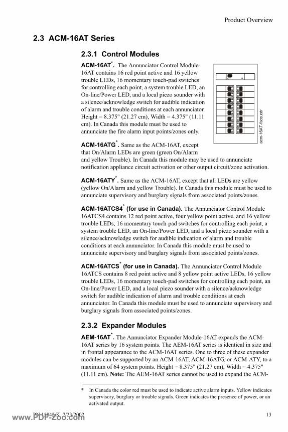
2.3.1 Control ModulesACM-16AT*. The Annunciator Control Module-16AT contains 16 red point active and 16 yellow trouble LEDs, 16 momentary touch-pad switches for controlling each point, a system trouble LED, an On-line/Power LED, and a local piezo sounder with a silence/acknowledge switch for audible indication of alarm and trouble conditions at each annunciator. Height = 8.375" (21.27 cm), Width = 4.375" (11.11 cm). In Canada this module must be used to annunciate the fire alarm input points/zones only.
ACM-16ATG*. Same as the ACM-16AT, except that On/Alarm LEDs are green (green On/Alarm and yellow Trouble). In Canada this module may be used to annunciate notification appliance circuit activation or other output circuit/zone activation.
ACM-16ATY*. Same as the ACM-16AT, except that all LEDs are yellow (yellow On/Alarm and yellow Trouble). In Canada this module must be used to annunciate supervisory and burglary signals from associated points/zones.
ACM-16ATCS4* (for use in Canada). The Annunciator Control Module 16ATCS4 contains 12 red point active, four yellow point active, and 16 yellow trouble LEDs, 16 momentary touch-pad switches for controlling each point, a system trouble LED, an On-line/Power LED, and a local piezo sounder with a silence/acknowledge switch for audible indication of alarm and trouble conditions at each annunciator. In Canada this module must be used to annunciate supervisory and burglary signals from associated points/zones.
ACM-16ATCS* (for use in Canada). The Annunciator Control Module 16ATCS contains 8 red point active and 8 yellow point active LEDs, 16 yellow trouble LEDs, 16 momentary touch-pad switches for controlling each point, an On-line/Power LED, and a local piezo sounder with a silence/acknowledge switch for audible indication of alarm and trouble conditions at each annunciator. In Canada this module must be used to annunciate supervisory and burglary signals from associated points/zones.
2.3.2 Expander ModulesAEM-16AT*. The Annunciator Expander Module-16AT expands the ACM-16AT series by 16 system points. The AEM-16AT series is identical in size and in frontal appearance to the ACM-16AT series. One to three of these expander modules can be supported by an ACM-16AT, ACM-16ATG, or ACM-ATY, to a maximum of 64 system points. Height = 8.375" (21.27 cm), Width = 4.375" (11.11 cm). Note: The AEM-16AT series cannot be used to expand the ACM-
* In Canada the color red must be used to indicate active alarm inputs. Yellow indicates supervisory, burglary or trouble signals. Green indicates the presence of power, or an activated output.
acm
-16A
T-fa
ce.c
dr
www.PDF-Zoo.com

Product Overview
14 PN 15842:K 7/23/2002
24AT, ACM-48A, or ACM-32A series. Expander LED colors need not match the control module LED colors for the expander to operate.
AEM-16ATY*. Same as the AEM-16AT but all LEDs are yellow (yellow On/Alarm and yellow Trouble).
AEM-16ATG*. Same as the AEM-16AT, but On/Alarm LEDs are green (green On/Alarm and yellow Trouble).
2.4 ACM-32A Series
2.4.1 Control ModulesACM-32A*. The Annunciator Control Module-32A contains 32 red point active LEDs, a system trouble LED, an On-line/Power LED, and a local piezo sounder with a silence/acknowledge switch for audible indication of alarm and trouble conditions at each annunciator. Height = 8.375" (21.27 cm), Width = 4.375" (11.11 cm). In Canada this module must be used to annunciate the fire alarm input points/zones only.
ACM-32AG*. Same as the ACM-32A, but On/Alarm LEDs are green (green On/Alarm and yellow Trouble). In Canada this module may be used to annunciate notification appliance circuit activation or other output circuit/zone activation.
ACM-32AY*. Same as the ACM-32A but with all LEDs yellow (yellow On/Alarm and yellow Trouble). In Canada this module must be used to annunciate supervisory and burglary signals from associated points/zones.
2.4.2 Expander ModulesAEM-32A*. The Annunciator Expander Module-32A expands the ACM-32A series by 32 system points. The AEM-32A (with red LEDs) is identical in frontal appearance to the ACM-32A. One expander module can be supported by an ACM-32A, ACM-32AG, or ACM-32AY, providing a maximum of 64 points. Height = 8.375" (21.27 cm), Width = 4.375" (11.11 cm). Note: The AEM-32A cannot be used to expand the ACM-24AT, ACM-48A, or ACM-32A series. Expander LED colors need not match the control module LED colors for the expander to operate.
AEM-32Y*. Same as the AEM-32A but with all LEDs yellow (yellow On/Alarm and yellow Trouble).
AEM-32G*. Same as the AEM-32A, but On/Alarm LEDs are green (green On/Alarm and yellow Trouble).
* In Canada the color red must be used to indicate active alarm inputs. Yellow indicates supervisory, burglary or trouble signals. Green indicates the presence of power, or an activated output.
acm
-32A
-face
3.cd
r
www.PDF-Zoo.com

Product Overview
PN 15842:K 7/23/2002 15
2.5 Cabinet & Panel Hardware
2.5.1 Surface-Mount Backboxes These backboxes provide a surface-mount enclosure for remote mounting annunciators. Knockouts are provided for use with 1/2" conduit. Dimensions are provided in Table 2-1.
ABS-1B, ABS-1. Mounts one annunciator directly to the ABS-1/1B without a dress plate. ABS-1 only fits ACM-16AT/ACM-32A series; the “B” version is black and is slightly deeper to fit either series. Note: This backbox will not support the installation of the Annunciator Key Switch or the Annunciator Phone Jack for Firefighters' Telephone.
ABS-2B, ABS-2. Mounts two annunciators directly to the ABS-2/2B without a dress plate. ABS-2 only fits ACM-16AT/ACM-32A series; the “B” version is black and is slightly deeper to fit either series. Note: This backbox will not support the installation of the Annunciator Key Switch or the Annunciator Phone Jack.
ABS-4D, ABS-4R. Mounts four annunciators, or two annunciators to the right of an NCA. This surface box can also be mounted semi-flush. Note: This backbox will not support the installation of the Annunciator Key Switch or the Annunciator Phone Jack for Firefighters' Telephone.
ABS-1TB, ABS-1T. Mounts one annunciator. Unlike the ABS-1/1B and ABS-2/2B, the ABS-1T/1TB has an increased depth that allows mounting of the Annunciator Phone Jack for Firefighters' Telephone and Annunciator Key Switch. ABS-1T only fits ACM-16AT/ACM-32A series; the “B” version is black and is slightly deeper to fit either series.
2.5.2 Flush-mount Backboxes These backboxes provide a flush-mount enclosure for remote mounting of annunciators. Knockouts are provided for use with 1/2" conduit. Dimensions are listed in Table 2-1. Backboxes include a trim plate and an adhesive-backed annunciator label for the dress plate (15824).
ABF-1B, ABF-1. Mounts one annunciator. ABF-1 only fits ACM-16AT/ACM-32A series; the “B” version is black and is slightly deeper to fit either series.
5043
9d2.
tif
ABS-1B, ABS-1
ABF-1B, ABF-1
abf-1
-iso.
cdr
www.PDF-Zoo.com

Product Overview
16 PN 15842:K 7/23/2002
ABF-2B, ABF-2. Mounts two annunciators. ABF-2 only fits ACM-16AT/ACM-32A series; the “B” version is black and is slightly deeper to fit either series.
ABF-4B, ABF-4. Mounts four annunciators. ABF-4 only fits ACM-16AT/ACM-32A series; the “B” version is black and is slightly deeper to fit either series.
2.5.3 Semi-flush-mount BackboxesThese backboxes provide a semi-flush-mount enclosure for remote mounting of annunciators. Knockouts are provided for use with 1/2" conduit. Dimensions are listed in Table 2-1.
ABF-1DB, ABF-1D. Mounts one annunciator behind an attractive smoked glass door with keylock. ABF-1D only fits ACM-16AT/ACM-32A series; the “B” version is black and is slightly deeper to fit either series.
ABF-2DB, ABF-2B. Mounts two annunciators or an NCA; otherwise the same as ABF-1D/1DB.
ABS-4D, ABS-4R. These backboxes can be surface-mounted or semi-flush mounted; see description in Section 2.5.1.
ABF-4B, ABF-4
abf-4
-iso.
cdr
ABF-
1-is
ovie
w.c
dr, a
bf-1
db.c
dr
ABF-1DB, ABF-1D
www.PDF-Zoo.com

Product Overview
PN 15842:K 7/23/2002 17
Table 2-1 Backbox Sizing Guide
Part Number Height Width Depth Color
ABS-18.5" (21.59 cm) 4.5" (11.43 cm)
1.375" (3.49 cm) GrayABS-1B 2.0" (5.08 cm) BlackABS-2
8.5" (21.59 cm) 8.920" (22.66 cm)1.375" (3.49 cm) Gray
ABS-2B 2.0" (5.08 cm) Black
ABS-4D,ABS-4DR
Box: 11.97" (30.40 cm)Door: 11.97" (30.40 cm)
Box: 19.87" (50.47 cm)Door: 19.87" (50.47 cm)
Box: 3.5" (8.89 cm)Door: 1.25" (3.18 cm)
Black or
RedABS-1T
9.938" (25.24 cm) 4.625" (11.75 cm)2.5" (6.35 cm) Gray
ABS-1TB 2.5" (6.35 cm) Black
ABF-1,ABF-1B
Box: 9.938" (25.24 cm)Trim plate:
11" (27.94 cm)
Box: 4.625" (11.75 cm)Trim plate:
6.25" (15.875 cm)2.5" (6.35 cm) Gray,
Black
ABF-2 Box: 9.938" (25.24 cm)Trim plate: 11" (27.94 cm)
Box: 9.188" (23.34 cm)Trim plate:
10.625" (26.99 cm)
1.375" (3.49 cm) Gray
ABF-2B 3.75" (9.525 cm) Black
ABF-4 Box: 9.938" (25.24 cm)Trim plate:
11.0" (27.94 cm)
Box: 17.750" (45.09 cm)Trim plate:
19.375" (49.21 cm)2.5" (6.35 cm)
Gray
ABF-4B Black
ABF-1D, ABF-1DB
Box: 9.938" (25.24 cm)Door: 11.0" (27.94 cm)
Box: 4.625" (11.75 cm)Door: 6" (15.24 cm)
Box: 2.5" (6.35 cm)Door: 0.75" (1.9 cm)
Gray,Black
ABF-2DBox: 9.938" (25.24 cm)Door: 11.0" (27.94 cm)
Box: 9.188" (20.80 cm)Door: 10.375" (26.35 cm)
Box: 2.5" (6.35 cm)Door: 0.75" (1.9 cm) Gray
ABF-2DB Box: 3.750" (9.53 cm)Door: 0.75" (1.9 cm) Black
www.PDF-Zoo.com
Product Overview
18 PN 15842:K 7/23/2002
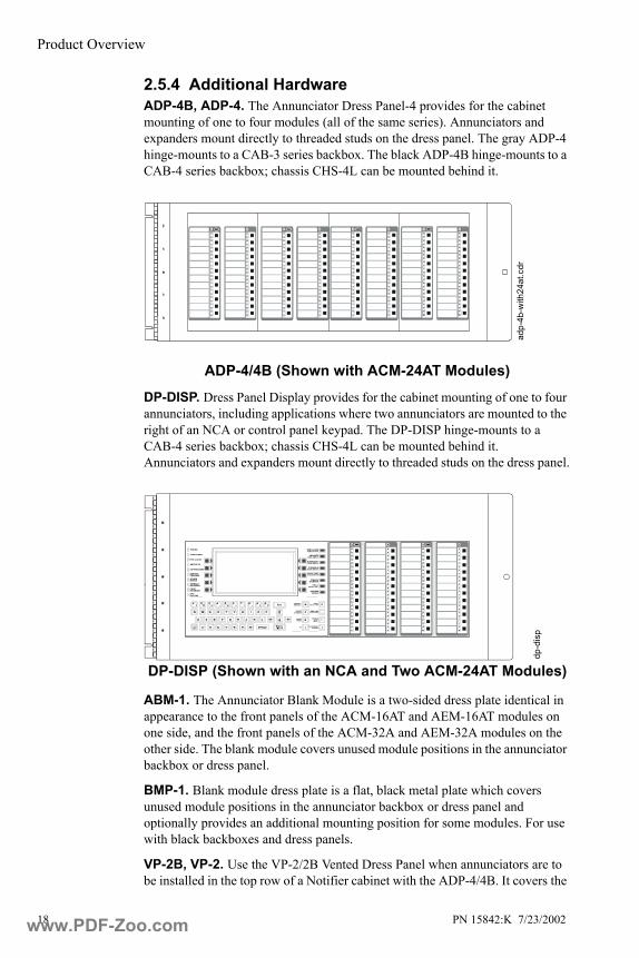
2.5.4 Additional Hardware ADP-4B, ADP-4. The Annunciator Dress Panel-4 provides for the cabinet mounting of one to four modules (all of the same series). Annunciators and expanders mount directly to threaded studs on the dress panel. The gray ADP-4 hinge-mounts to a CAB-3 series backbox. The black ADP-4B hinge-mounts to a CAB-4 series backbox; chassis CHS-4L can be mounted behind it.
DP-DISP. Dress Panel Display provides for the cabinet mounting of one to four annunciators, including applications where two annunciators are mounted to the right of an NCA or control panel keypad. The DP-DISP hinge-mounts to a CAB-4 series backbox; chassis CHS-4L can be mounted behind it. Annunciators and expanders mount directly to threaded studs on the dress panel.
ABM-1. The Annunciator Blank Module is a two-sided dress plate identical in appearance to the front panels of the ACM-16AT and AEM-16AT modules on one side, and the front panels of the ACM-32A and AEM-32A modules on the other side. The blank module covers unused module positions in the annunciator backbox or dress panel.
BMP-1. Blank module dress plate is a flat, black metal plate which covers unused module positions in the annunciator backbox or dress panel and optionally provides an additional mounting position for some modules. For use with black backboxes and dress panels.
VP-2B, VP-2. Use the VP-2/2B Vented Dress Panel when annunciators are to be installed in the top row of a Notifier cabinet with the ADP-4/4B. It covers the
adp-
4b-w
ith24
at.c
dr
ADP-4/4B (Shown with ACM-24AT Modules)
dp-d
isp
DP-DISP (Shown with an NCA and Two ACM-24AT Modules)
www.PDF-Zoo.com
Product Overview
PN 15842:K 7/23/2002 19
gap between the ADP-4/4B and the top of the cabinet. It secures to the cabinet with two screws. The “B” version is black.
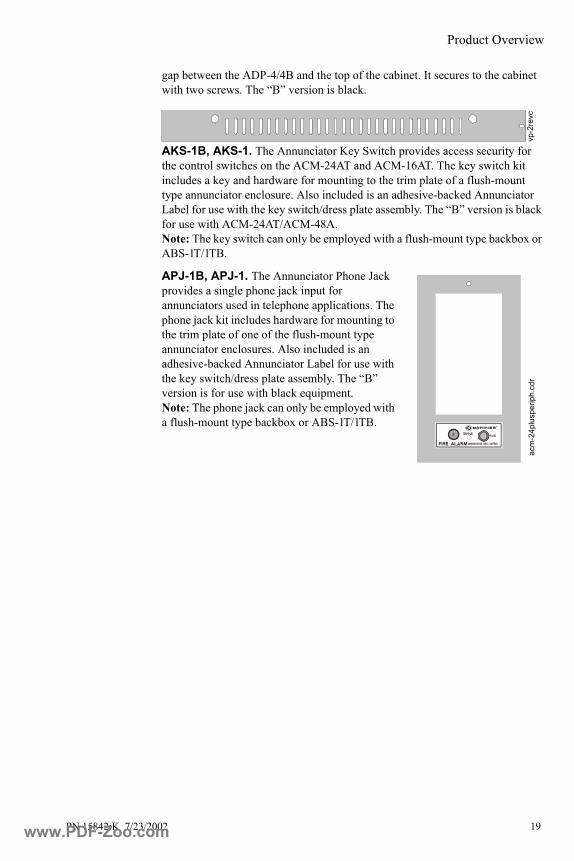
AKS-1B, AKS-1. The Annunciator Key Switch provides access security for the control switches on the ACM-24AT and ACM-16AT. The key switch kit includes a key and hardware for mounting to the trim plate of a flush-mount type annunciator enclosure. Also included is an adhesive-backed Annunciator Label for use with the key switch/dress plate assembly. The “B” version is black for use with ACM-24AT/ACM-48A.Note: The key switch can only be employed with a flush-mount type backbox or ABS-1T/1TB.
APJ-1B, APJ-1. The Annunciator Phone Jack provides a single phone jack input for annunciators used in telephone applications. The phone jack kit includes hardware for mounting to the trim plate of one of the flush-mount type annunciator enclosures. Also included is an adhesive-backed Annunciator Label for use with the key switch/dress plate assembly. The “B” version is for use with black equipment. Note: The phone jack can only be employed with a flush-mount type backbox or ABS-1T/1TB.
vp-2
revc
acm
-24p
lusp
erip
h.cd
r
www.PDF-Zoo.com

Design Considerations
20 PN 15842:K 7/23/2002
Section 3 Design Considerations3.1 Limits
The standard Notifier EIA-485 circuit can drive up to 32 annunciators with expanders. One system can mix ACM-24AT, ACM-48A, ACM-16AT, ACM-32A, and their expanders with other ACS devices such as LDM, TM-4, etc. An end-of-line resistor must be installed or enabled on the last ACS device on the circuit. The number of annunciators that can engage in two-way communication depends on the number of addresses available with a given fire alarm control panel. The actual number of ACS devices that can be powered in a particular system depends on the current available from the control panel’s power supply. Refer to the installation manual for the particular control panel for more details. For information on boosting the EIA-485 circuit signal or adding additional devices (not addresses), see the RPT-485W/RPT-485WF Installation Manual.
3.2 Wire RunsCommunication between the control panel and ACS annunciators occurs over a power-limited 2-wire EIA-485 serial interface. This communication is supervised by the fire alarm control panel. Each annunciator/expander module also requires a power-limited 24 VDC power connection. This power circuit is inherently supervised; loss of power registers as a communication failure at the control panel. The ACS can also be powered from a power-limited and regulated remote power supply listed for fire-protective signalling use
Note: (AM2020/AFP1010 installations only) SIB-2048A/SIB-NET can support two EIA-485 circuits, each capable of spanning 6,000 feet at 16 AWG. For more details, refer to Appendix P.
3.3 EIA-485 Wiring Specifications Wire the EIA-485 circuit as shown in Section 4.5 “EIA-485 Circuit Connections”. These requirements must be followed:
• The EIA-485 circuit cannot be T-Tapped; it must be wired in a continuous fashion to function properly.
• There is a maximum of 6,000 feet at 16 AWG between the panel and the last annunciator on the EIA-485 circuit (subject to your system’s power restrictions).
AnnunciatorFire Alarm Control Panel
ACS Power(12 to 18 AWG)
filtered & power-limited
Two-wire EIA-485 Circuit(Maximum of 6,000 feet)
power-limited & supervised
caba
3.w
mf,
ACM
-24A
Tfac
e.cd
r
www.PDF-Zoo.com
Design Considerations
PN 15842:K 7/23/2002 21
• The wiring size must be a 12 AWG to 18 AWG twisted shielded pair cable having a characteristic impedance of 120 ohms, +/- 20%.
• Limit the total wire resistance to 100 ohms on the EIA-485 circuit, and 10 ohms on the annunciator power circuit.
• Do not run cable adjacent to, or in the same conduit as, 120 volts AC service, “noisy” electrical circuits that are powering mechanical bells or horns, audio circuits above 25 volts RMS, motor control circuits, or SCR power circuits.
• If annunciators are to be mounted in a separate cabinet or powered by a remote power supply, see Figure 3-2 Using Multiple Power Supplies With the EIA-485 Circuit. For information on boosting the EIA-485 circuit signal or adding additional devices (not addresses), see the RPT-485W/RPT-485WF Installation Manual.
All power must be turned off when connecting the annunciator.
3.4 Receive/Transmit and Receive Only Configuration Receive/Transmit AnnunciatorsAnnunciators that are configured to serve as full function annunciators can both receive status information as well as transmit commands to the control panel. This allows the annunciator to remotely execute functions of the control panel in addition to displaying the status of the system.
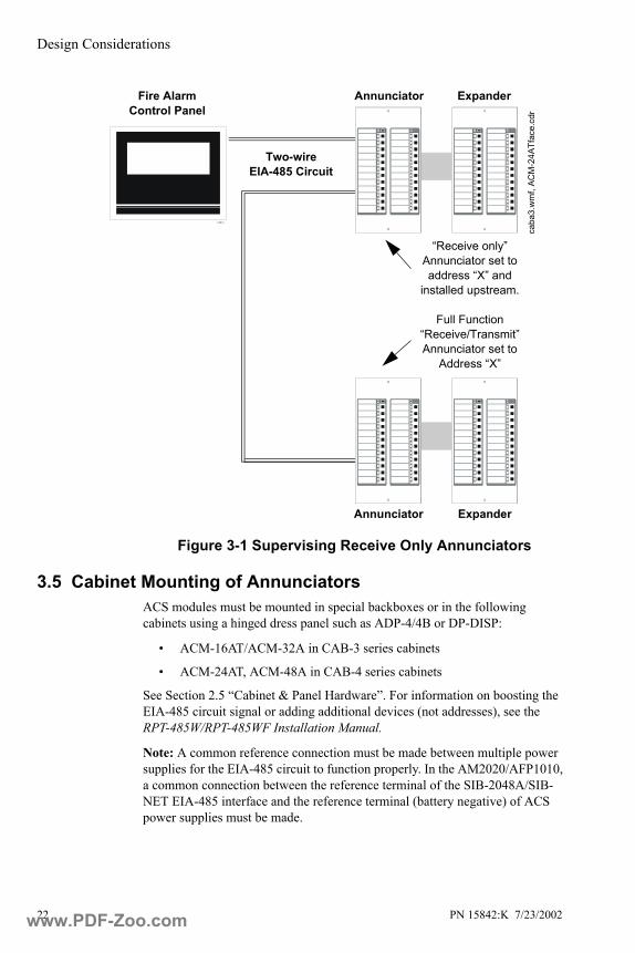
Receive Only AnnunciatorsFor redundant annunciation of system points, annunciators can be configured as “Receive Only” annunciators. Receive Only annunciators must be set to the same address as the annunciators they duplicate. Receive Only annunciators intercept information being transmitted to a “Receive/Transmit” annunciator for duplication at an intermediate display location. When configured for Receive Only operation, they cannot be used to send information to the system, and as a result are not supervised by the control panel. They cannot perform remote functions such as Acknowledge, Signal Silence, or System Reset. Control switches on Receive Only annunciators can be used only for local functions, such as lamp test. Wiring to Receive Only annunciators may be supervised by installing the modules “upstream” of fully supervised, Receive/Transmit annunciators along the EIA-485 line (see Figure 3-1).
www.PDF-Zoo.com
Design Considerations
22 PN 15842:K 7/23/2002
Figure 3-1 Supervising Receive Only Annunciators
3.5 Cabinet Mounting of Annunciators ACS modules must be mounted in special backboxes or in the following cabinets using a hinged dress panel such as ADP-4/4B or DP-DISP:
• ACM-16AT/ACM-32A in CAB-3 series cabinets
• ACM-24AT, ACM-48A in CAB-4 series cabinets
See Section 2.5 “Cabinet & Panel Hardware”. For information on boosting the EIA-485 circuit signal or adding additional devices (not addresses), see the RPT-485W/RPT-485WF Installation Manual.
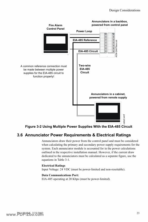
Note: A common reference connection must be made between multiple power supplies for the EIA-485 circuit to function properly. In the AM2020/AFP1010, a common connection between the reference terminal of the SIB-2048A/SIB-NET EIA-485 interface and the reference terminal (battery negative) of ACS power supplies must be made.
AnnunciatorFire Alarm Control Panel
Two-wire EIA-485 Circuit
caba
3.w
mf,
ACM
-24A
Tfac
e.cd
r
Annunciator Expander
Expander
“Receive only” Annunciator set to address “X” and
installed upstream.
Full Function “Receive/Transmit” Annunciator set to
Address “X”
www.PDF-Zoo.com
Design Considerations
PN 15842:K 7/23/2002 23
Figure 3-2 Using Multiple Power Supplies With the EIA-485 Circuit
3.6 Annunciator Power Requirements & Electrical RatingsAnnunciators draw their power from the control panel and must be considered when calculating the primary and secondary power supply requirements for the system. Each annunciator module is accounted for in the power calculations outlined in the respective installation manual. However, if the current draw dedicated to the annunciators must be calculated as a separate figure, use the equations in Table 3-1.
Electrical RatingsInput Voltage: 24 VDC (must be power-limited and non-resettable).
Data Communications Port: EIA-485 operating at 20 Kbps (must be power-limited).
EIA-485 Reference
Annunciators in a backbox, powered from control panelFire Alarm
Control Panel
EIA-485 Circuit
caba
3.w
mf
Annunciators in a cabinet, powered from remote supply
Two-wire EIA-485 Circuit
Power Loop
A common reference connection must be made between multiple power supplies for the EIA-485 circuit to
function properly!
ACM
-24A
Tfac
e.cd
r
www.PDF-Zoo.com
Design Considerations
24 PN 15842:K 7/23/2002
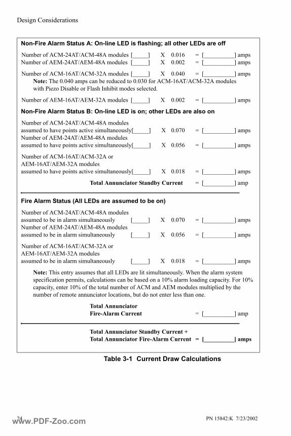
Table 3-1 Current Draw Calculations
Non-Fire Alarm Status A: On-line LED is flashing; all other LEDs are off
Number of ACM-24AT/ACM-48A modules [_____] X 0.016 = [__________] amps Number of AEM-24AT/AEM-48A modules [_____] X 0.002 = [__________] amps
Number of ACM-16AT/ACM-32A modules [_____] X 0.040 = [__________] amps Note: The 0.040 amps can be reduced to 0.030 for ACM-16AT/ACM-32A modules with Piezo Disable or Flash Inhibit modes selected.
Number of AEM-16AT/AEM-32A modules [_____] X 0.002 = [__________] amps
Non-Fire Alarm Status B: On-line LED is on; other LEDs are also on
Number of ACM-24AT/ACM-48A modules assumed to have points active simultaneously[_____] X 0.070 = [__________] amps Number of AEM-24AT/AEM-48A modules assumed to have points active simultaneously[_____] X 0.056 = [__________] amps
Number of ACM-16AT/ACM-32A or AEM-16AT/AEM-32A modules assumed to have points active simultaneously[_____] X 0.018 = [__________] amps
Total Annunciator Standby Current = [__________] amp
Fire Alarm Status (All LEDs are assumed to be on)
Number of ACM-24AT/ACM-48A modules assumed to be in alarm simultaneously [_____] X 0.070 = [__________] amps Number of AEM-24AT/AEM-48A modules assumed to be in alarm simultaneously [_____] X 0.056 = [__________] amps
Number of ACM-16AT/ACM-32A or AEM-16AT/AEM-32A modules assumed to be in alarm simultaneously [_____] X 0.018 = [__________] amps
Note: This entry assumes that all LEDs are lit simultaneously. When the alarm system specification permits, calculations can be based on a 10% alarm loading capacity. For 10% capacity, enter 10% of the total number of ACM and AEM modules multiplied by the number of remote annunciator locations, but do not enter less than one.
Total Annunciator Fire-Alarm Current = [__________] amp
Total Annunciator Standby Current + Total Annunciator Fire-Alarm Current = [__________] amps
www.PDF-Zoo.com

Installation, Configuration, and Programming
PN 15842:K 7/23/2002 25
Section 4 Installation, Configuration, and ProgrammingThis section provides an overview of installation procedures for ACS annunciators.
For wiring & programming details that are unique to a specific fire alarm control panel, refer to that panel's appendix in this manual, and to that panel's programming guide (see Section 1.2 “Related Documentation” for part numbers). Refer to the appendix section if, for example, you need to locate the terminal block on the control panel to which you would connect a particular ACS circuit.
For operating information, see Section 5 “LED and Keypad-Switch Functions” which provides details on LED and switch functions.
4.1 Installation Checklist1. Mount and ground the cabinet or backbox (Section 4.3).
2. Pull wiring into backbox and connect removable terminal blocks to wires (Section 4.3, Section 4.5, Section 4.9).
3. Connect shield for EIA-485 circuit (Section 4.6).
4. Connect Earth Ground to a mounting screw on the backbox or cabinet (Section 4.8).
5. Place slide-in labels in annunciators and expanders; attach adhesive labels to trim plates (Section 4.10).
6. Mount key switch and/or phone jack onto annunciators (Section 4.11).
7. Mount and connect annunciators and expanders (Section 4.4).
8. Configure annunciators for the number of installed expanders (Section 4.12.3).
9. Set DIP switches & module addresses (Section 4.12).
10. Make all electrical connections:• EIA-485 circuit & End-of-line resistor (Section 4.5 and Section 4.7).• Power circuit (Section 4.9)• ACM-16AT, ACM-32A and expanders only: Supervising devices
(Section 4.14)
11. Attach doors to semi-flush-mount backboxes (Section 4.4).
12. Power up system according to instructions in the control panel manual.
13. Program the control panel (Section 4.15).
14. ACM-24AT, ACM-48A and expanders only: Set LED colors to correspond with panel-programming selections (Section 5.1).
15. Test annunciators (Section 4.15).
www.PDF-Zoo.com
Installation, Configuration, and Programming
26 PN 15842:K 7/23/2002
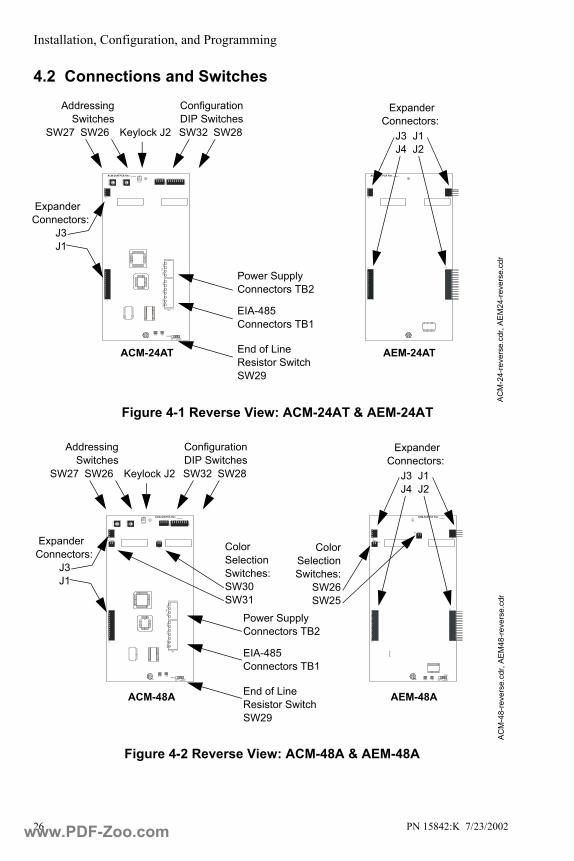
4.2 Connections and Switches
ACM-24ATPCA Rev. ____54
32
1 0 9
87
654
32
1 0 9
87
6 54
32
1 0 9
87
654
32
1 0 9
87
6
SW32
SW28
KEYLOCK
J2
PWR SUPPLY
+24V
RE
FAC
S+A
CS-
RE
FEG
ND
EIA485 INTFCTB1
RXB TXBSW29
DISABLE ENABLE ELR TERMINATE
J1
SW27
T
ENS
SW26
O
NES
J3
TB2
AEM-24ATPCA Rev. ____
J1
J3 J4
J2
ACM
-24-
reve
rse.
cdr,
AEM
24-re
vers
e.cd
r
Configuration DIP Switches
EIA-485 Connectors TB1
Figure 4-1 Reverse View: ACM-24AT & AEM-24AT
Keylock J2
End of Line Resistor Switch SW29
SW32 SW28
AddressingSwitches
SW27 SW26
Expander Connectors:
Power Supply Connectors TB2
J3 J1J4 J2
Expander Connectors:
J3J1
ACM-24AT AEM-24AT
ACM-48APCA Rev. ____54
32
1 0 9
87
654
32
1 0 9
87
6 54
32
1 0 9
87
654
32
1 0 9
87
6
SW27
T
ENS
SW32
SW26
ON
ES
SW28
KEYLOCK
J2
J1
SW31
SW30
J3
PWR SUPPLY
+24V
RE
FAC
S+A
CS-
RE
FEG
ND
EIA485 INTFCTB1
TB2
RXB TXBSW29
DISABLE ENABLE ELR TERMINATE
AEM-48APCA Rev. ____
SW25
SW26
RXB TXB
SW29
DISABLE ENABLE ELR TERMINATE
J2
J1
J3 J4
ACM
-48-
reve
rse.
cdr,
AEM
48-re
vers
e.cd
r
Configuration DIP Switches
Power Supply Connectors TB2
EIA-485 Connectors TB1
Figure 4-2 Reverse View: ACM-48A & AEM-48A
Keylock J2
End of Line Resistor Switch SW29
SW32 SW28
AddressingSwitches
SW27 SW26
Color Selection Switches:SW30SW31
ColorSelectionSwitches:
SW26SW25
Expander Connectors:
J3 J1J4 J2
Expander Connectors:
J3J1
ACM-48A AEM-48A
www.PDF-Zoo.com

Installation, Configuration, and Programming
PN 15842:K 7/23/2002 27
Annunciator Key Switch Connector
Configuration DIP Switches
Figure 4-3 Reverse View: ACM-16AT, ACM-32A and expanders
Addressing Switches
EIA-485 Connectors TB2
Power Supply Connectors TB1
ExpanderConnector J1
Tens OnesAnnunciator Address
Annunciator Key Switch Connector
DIP Switches
Dip Switch set to “OFF” position
Dip Switch set to “ON” position
Figure 4-4 End View: ACM-16AT and ACM-32A
www.PDF-Zoo.com
Installation, Configuration, and Programming
28 PN 15842:K 7/23/2002
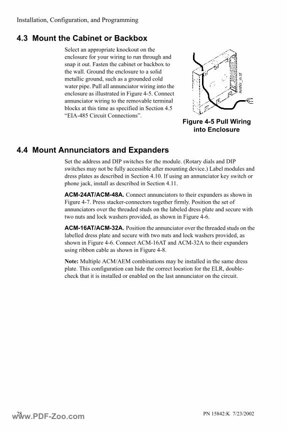
4.3 Mount the Cabinet or Backbox Select an appropriate knockout on the enclosure for your wiring to run through and snap it out. Fasten the cabinet or backbox to the wall. Ground the enclosure to a solid metallic ground, such as a grounded cold water pipe. Pull all annunciator wiring into the enclosure as illustrated in Figure 4-5. Connect annunciator wiring to the removable terminal blocks at this time as specified in Section 4.5 “EIA-485 Circuit Connections”.
4.4 Mount Annunciators and Expanders Set the address and DIP switches for the module. (Rotary dials and DIP switches may not be fully accessible after mounting device.) Label modules and dress plates as described in Section 4.10. If using an annunciator key switch or phone jack, install as described in Section 4.11.
ACM-24AT/ACM-48A. Connect annunciators to their expanders as shown in Figure 4-7. Press stacker-connectors together firmly. Position the set of annunciators over the threaded studs on the labeled dress plate and secure with two nuts and lock washers provided, as shown in Figure 4-6.
ACM-16AT/ACM-32A. Position the annunciator over the threaded studs on the labelled dress plate and secure with two nuts and lock washers provided, as shown in Figure 4-6. Connect ACM-16AT and ACM-32A to their expanders using ribbon cable as shown in Figure 4-8.
Note: Multiple ACM/AEM combinations may be installed in the same dress plate. This configuration can hide the correct location for the ELR, double-check that it is installed or enabled on the last annunciator on the circuit.
Figure 4-5 Pull Wiring into Enclosure
AnW
ir_in
.tif
www.PDF-Zoo.com
Installation, Configuration, and Programming
PN 15842:K 7/23/2002 29
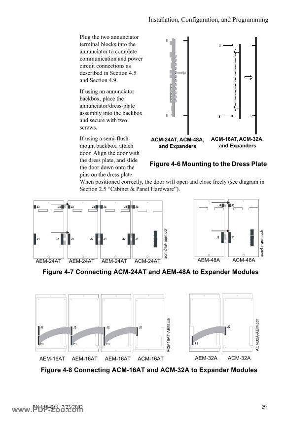
Plug the two annunciator terminal blocks into the annunciator to complete communication and power circuit connections as described in Section 4.5 and Section 4.9.
If using an annunciator backbox, place the annunciator/dress-plate assembly into the backbox and secure with two screws.
If using a semi-flush-mount backbox, attach door. Align the door with the dress plate, and slide the door down onto the pins on the dress plate. When positioned correctly, the door will open and close freely (see diagram in Section 2.5 “Cabinet & Panel Hardware”).
Figure 4-6 Mounting to the Dress Plate
ACM-16AT, ACM-32A, and Expanders
ACM-24AT, ACM-48A, and Expanders
Figure 4-7 Connecting ACM-24AT and AEM-48A to Expander Modules
TB2 PWR SUPPLY
+24V
REF
RS48
5+R
S485
-R
EFE
GN
D
RS485 INTFCTB1
J2J1
J3
J1
J4 J3
J1
J3 J4
J2 J1
J3 J4
J2
acm
24at
-aem
.cdr
ACM-24ATAEM-24ATAEM-24ATAEM-24AT
J2
J4
J1
J3
J2
TB2 PWR SUPPLY
+24V
REF
RS4
85+
RS4
85-
REF
EGND
RS485 INTFCTB1
acm
48-a
em.c
drACM-48AAEM-48A
J2J2
P3
J2
P3
J2
P3
J2
P3
ACM
16AT
-AEM
.cdr
Figure 4-8 Connecting ACM-16AT and ACM-32A to Expander Modules
ACM
32A-
AEM
.cdr
ACM-16ATAEM-16ATAEM-16ATAEM-16AT ACM-32AAEM-32A
www.PDF-Zoo.com
Installation, Configuration, and Programming
30 PN 15842:K 7/23/2002
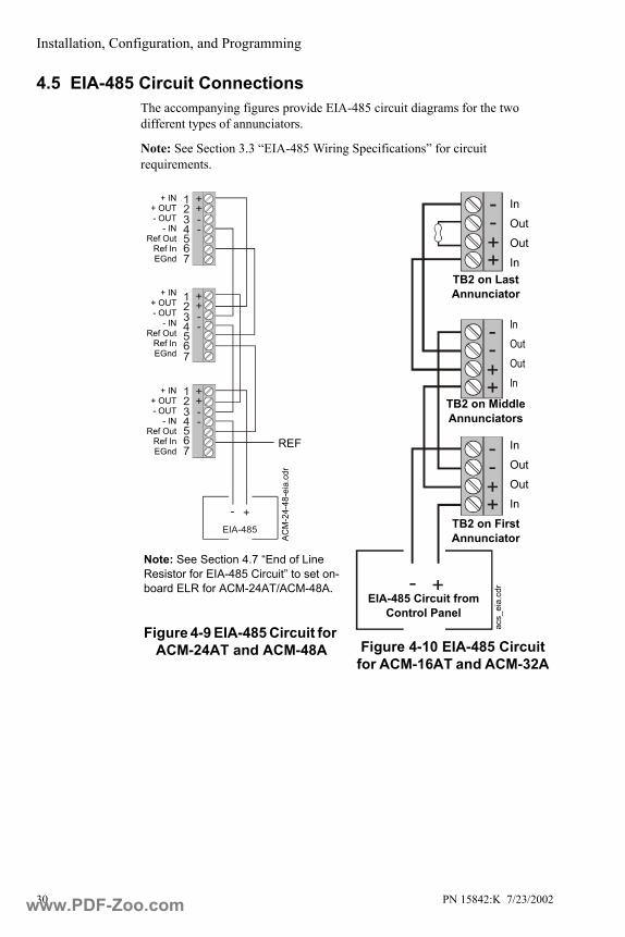
4.5 EIA-485 Circuit Connections The accompanying figures provide EIA-485 circuit diagrams for the two different types of annunciators.
Note: See Section 3.3 “EIA-485 Wiring Specifications” for circuit requirements.
--
++
EIA-485
--
++
--
++
34
12
7
56
34
12
7
56
34
12
7
56
- +
ACM
-24-
48-e
ia.c
dr
REF
+ IN+ OUT- OUT
- INRef Out
Ref InEGnd
+ IN+ OUT- OUT
- INRef Out
Ref InEGnd
+ IN+ OUT- OUT
- INRef Out
Ref InEGnd
Note: See Section 4.7 “End of Line Resistor for EIA-485 Circuit” to set on-board ELR for ACM-24AT/ACM-48A.
Figure 4-9 EIA-485 Circuit for ACM-24AT and ACM-48A
--++
--++
--++
- +
Figure 4-10 EIA-485 Circuit for ACM-16AT and ACM-32A
TB2 on Last Annunciator
EIA-485 Circuit from Control Panel
acs_
eia.
cdr
InOutOutIn
TB2 on First Annunciator
TB2 on Middle Annunciators
InOutOutIn
InOutOutIn
www.PDF-Zoo.com

Installation, Configuration, and Programming
PN 15842:K 7/23/2002 31
4.6 Shielding the EIA-485 CircuitThe EIA-485 circuit must be wired using a twisted-shielded pair cable having a Characteristic Impedance of 120 ohms, +/- 20%. Do not run cable adjacent to, or in the same conduit as, 120-volt AC service, noisy electrical circuits that are powering mechanical bells or horns, audio circuits above 25 Vrms, motor control circuits, or SCR power circuits. All enclosures, including the FACP backbox, must be connected to earth ground! Never use the shield for grounding purposes. Terminate the EIA-485 shield at the Fire Alarm Control Panel only.
• When the EIA-485 shield is in conduit: Connect it to system reference (system common). The shield can enter the cabinet, but must be insulated from the cabinet (no electrical contact). Between annunciators, wire-nut multiple shields together (which can be inside of the respective enclosure, but can not contact the enclosure).
• When the EIA-485 shield is not in conduit: Terminate the shield at the outside of the FACP backbox (ground). Do not allow the shield to enter or even touch the cabinet. Between annunciators, wire-nut multiple shields together outside of the respective enclosures (see Figure 4-11).
4.7 End of Line Resistor for EIA-485 CircuitFor the last device on the EIA-485 circuit, an end-of-line resistor must be installed or enabled (depending on the type of ACS device).
• For ACM-24AT or ACM-48A, set SW29 to “ENABLE” to install the built-in end-of-line resistor (see Figure 4-12).
• For ACM-16AT or ACM-32A, install a 120-ohm End-of-Line Resistor (Notifier Part Number 71244, supplied with the annunciator) must be installed at the last annunciator on the EIA-485 circuit (see Figure 4-10 on page 30).
All other ACS annunciators should be set to “DISABLE” or the ELR removed. Power must be turned off when connecting the annunciator to avoid damaging the equipment.
Figure 4-11 Terminating the Shield w
ireco
nd.p
cxEnclosure Annunciator
RXB TXBSW29
DISABLE ENABLE ELR TERMINATE
Figure 4-12 SW29 on ACM-24AT or ACM-48A
ACM
-SW
29.c
dr
www.PDF-Zoo.com

Installation, Configuration, and Programming
32 PN 15842:K 7/23/2002
4.8 Earth GroundConnect Earth Ground to a mounting screw on the backbox or cabinet During mounting (see Section 4.3), the backbox or cabinet should have been connected to a solid earth ground such as a cold water pipe.
• ACM-24AT, ACM-48A: Ground is on the EIA-485 terminal block.
• ACM-16AT and ACM-32A: Ground is on the Power terminal block.
4.9 Main Power Supply ConnectionsThe ACS power source must be filtered, non-resettable, 24 VDC listed for fire-protective signalling use. Sources include main power supplies, auxiliary power supplies, and on-board power supplies (integral to fire alarm control panel).
The power run to the annunciator need not contain a Power Supervision Relay because loss of power is inherently supervised through communication loss (loss of EIA-485 communication is registered at the control panel during loss of power to the annunciator).
See accompanying figures for power supply diagrams:
• Section 4-13 “Power Circuit for ACM-24AT and ACM-48A”.
• Section 4-14 “Power Circuit for ACM-16AT and ACM-32A”.
For details about connections to particular control panels, see the appropriate appendix in this manual.
Note: All power must be turned off when connecting the 24 VDC power to the annunciator. Reapply power according to the instructions in your control panel manual.
www.PDF-Zoo.com

Installation, Configuration, and Programming
PN 15842:K 7/23/2002 33
- +
++
++
++
TB2 PWR SUPPLY
TB2 PWR SUPPLY
TB2 PWR SUPPLY
+24 VDC In+24 VDC Out
Reference OutReference In
Note: On ACM-24AT and ACM-48A, earth ground is on TB1 with the EIA-485 connection.
Figure 4-13 Power Circuit forACM-24AT and ACM-48A
24 VDC Power
ACM
-24-
48-p
wr.c
dr
+24 VDC In+24 VDC Out
Reference OutReference In
+24 VDC In+24 VDC Out
Reference OutReference In
+ -
++
----
--
--
++
++
Figure 4-14 Power Circuit forACM-16AT and ACM-32A
24 VDC Power
TB1
Jumper for supervisory devices (see Section 4.14)
ACS1
6-32
-pw
r.cdr
N.C. Trouble InputsN.C. Trouble Inputs
Common InCommon Out
Power InPower Out
Earth Ground
N.C. Trouble InputsN.C. Trouble Inputs
Common InCommon Out
Power InPower Out
Earth Ground
N.C. Trouble InputsN.C. Trouble Inputs
Common InCommon Out
Power InPower Out
Earth Ground
TB1
TB1
www.PDF-Zoo.com
Installation, Configuration, and Programming
34 PN 15842:K 7/23/2002
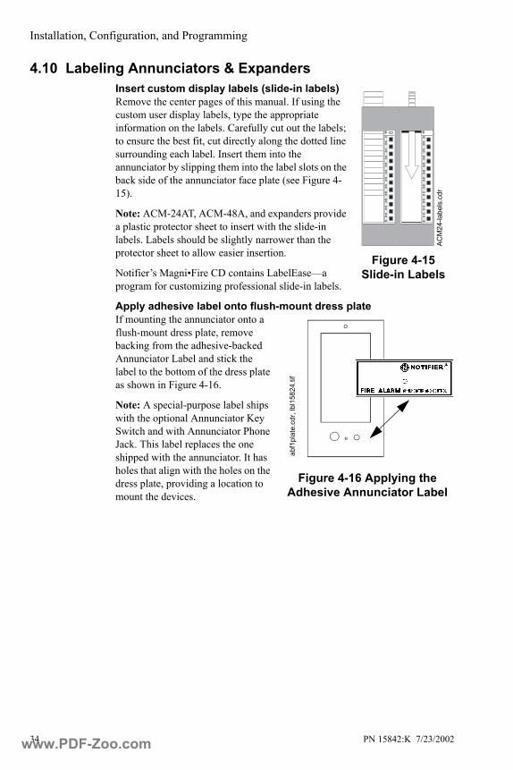
4.10 Labeling Annunciators & ExpandersInsert custom display labels (slide-in labels)Remove the center pages of this manual. If using the custom user display labels, type the appropriate information on the labels. Carefully cut out the labels; to ensure the best fit, cut directly along the dotted line surrounding each label. Insert them into the annunciator by slipping them into the label slots on the back side of the annunciator face plate (see Figure 4-15).
Note: ACM-24AT, ACM-48A, and expanders provide a plastic protector sheet to insert with the slide-in labels. Labels should be slightly narrower than the protector sheet to allow easier insertion.
Notifier’s Magni•Fire CD contains LabelEase—a program for customizing professional slide-in labels.
Apply adhesive label onto flush-mount dress plateIf mounting the annunciator onto a flush-mount dress plate, remove backing from the adhesive-backed Annunciator Label and stick the label to the bottom of the dress plate as shown in Figure 4-16.
Note: A special-purpose label ships with the optional Annunciator Key Switch and with Annunciator Phone Jack. This label replaces the one shipped with the annunciator. It has holes that align with the holes on the dress plate, providing a location to mount the devices.
Figure 4-15 Slide-in Labels
ACM
24-la
bels
.cdr
Figure 4-16 Applying the Adhesive Annunciator Label
abf1
plat
e.cd
r, lb
l158
24.ti
f
www.PDF-Zoo.com
Installation, Configuration, and Programming
PN 15842:K 7/23/2002 35
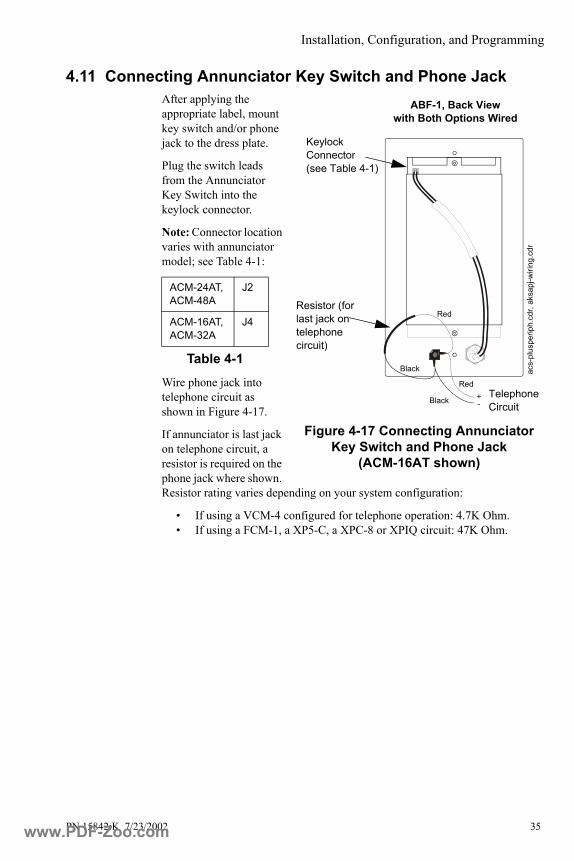
4.11 Connecting Annunciator Key Switch and Phone Jack After applying the appropriate label, mount key switch and/or phone jack to the dress plate.
Plug the switch leads from the Annunciator Key Switch into the keylock connector.
Note: Connector location varies with annunciator model; see Table 4-1:
Wire phone jack into telephone circuit as shown in Figure 4-17.
If annunciator is last jack on telephone circuit, a resistor is required on the phone jack where shown. Resistor rating varies depending on your system configuration:
• If using a VCM-4 configured for telephone operation: 4.7K Ohm.• If using a FCM-1, a XP5-C, a XPC-8 or XPIQ circuit: 47K Ohm.
ACM-24AT, ACM-48A
J2
ACM-16AT, ACM-32A
J4
Table 4-1
-+ Telephone
Circuit
Red
Red
Black
Black
acs-
plus
perip
h.cd
r, ak
sapj
-wiri
ng.c
dr
Keylock Connector (see Table 4-1)
Resistor (for last jack on telephone circuit)
Figure 4-17 Connecting Annunciator Key Switch and Phone Jack
(ACM-16AT shown)
ABF-1, Back View with Both Options Wired
www.PDF-Zoo.com
Installation, Configuration, and Programming
36 PN 15842:K 7/23/2002
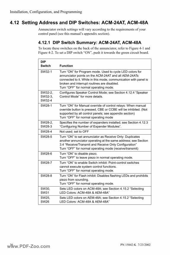
4.12 Setting Address and DIP Switches: ACM-24AT, ACM-48AAnnunciator switch settings will vary according to the requirements of your control panel (see this manual’s appendix section).
4.12.1 DIP Switch Summary: ACM-24AT, ACM-48A To locate these switches on the back of the annunciator, refer to Figure 4-1 and Figure 4-2. To set a DIP switch “ON”, push it towards the green circuit board.
DIP Switch Function
SW32-1 Turn “ON” for Program mode. Used to cycle LED colors for annunciator points on the ACM-24AT and all AEM-24ATs connected to it. While in this mode, communication with panel is broken and interrupt routines are disabled. Turn “OFF” for normal operating mode.
SW32-2, SW32-3, SW32-4
Configures Speaker Control Mode; see Section 4.12.4 “Speaker Control Mode” for more details.
SW28-1 Turn “ON” for Manual override of control relays: When manual override button is pressed, CBE or CCBE will be inhibited. (Not supported by all control panels; see appendix section)Turn “OFF” for normal operating mode
SW28-2, SW28-3
Specifies the number of expanders installed; see Section 4.12.3 “Configuring Number of Expander Modules”.
SW28-4 Not used; set to OFFSW28-5 Turn “ON” to set annunciator as Receive Only: Duplicates
another annunciator operating at the same address; see Section 3.4 “Receive/Transmit and Receive Only Configuration”Turn “OFF” for normal operating mode (receive/transmit)
SW28-6 Turn “ON” to disable piezo. Turn “OFF” to leave piezo in normal operating mode.
SW28-7 Turn “ON” to enable Switch inhibit: Point-control switches cannot execute system control functions.Turn “OFF” for normal operating mode.
SW28-8 Turn “ON” for Flash inhibit: Disables flashing LEDs and prohibits piezo from sounding.Turn “OFF” for normal operating mode.
SW30, SW31
Sets LED colors on ACM-48A; see Section 4.15.2 “Selecting LED Colors: ACM-48A & AEM-48A”
SW25, SW26
Sets LED colors on AEM-48A; see Section 4.15.2 “Selecting LED Colors: ACM-48A & AEM-48A”
www.PDF-Zoo.com
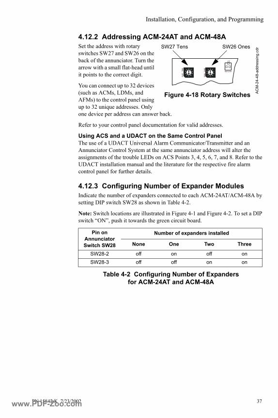
Installation, Configuration, and Programming
PN 15842:K 7/23/2002 37
4.12.2 Addressing ACM-24AT and ACM-48ASet the address with rotary switches SW27 and SW26 on the back of the annunciator. Turn the arrow with a small flat-head until it points to the correct digit.
You can connect up to 32 devices (such as ACMs, LDMs, and AFMs) to the control panel using up to 32 unique addresses. Only one device per address can answer back.
Refer to your control panel documentation for valid addresses.
Using ACS and a UDACT on the Same Control PanelThe use of a UDACT Universal Alarm Communicator/Transmitter and an Annunciator Control System at the same annunciator address will alter the assignments of the trouble LEDs on ACS Points 3, 4, 5, 6, 7, and 8. Refer to the UDACT installation manual and the literature for the respective fire alarm control panel for further details.
4.12.3 Configuring Number of Expander ModulesIndicate the number of expanders connected to each ACM-24AT/ACM-48A by setting DIP switch SW28 as shown in Table 4-2.
Note: Switch locations are illustrated in Figure 4-1 and Figure 4-2. To set a DIP switch “ON”, push it towards the green circuit board.
Table 4-2 Configuring Number of Expanders for ACM-24AT and ACM-48A
Pin on Annunciator Switch SW28
Number of expanders installed
None One Two Three
SW28-2 off on off onSW28-3 off off on on
54
32
1 0 9
87
654
32
1 0 9
87
6 54
32
1 0 9
87
654
32
1 0 9
87
6
KEYLOCK
J2
SW27
T
ENS
SW26
O
NES
ACM
-24-
48-a
ddre
ssin
g.cd
r
Figure 4-18 Rotary Switches
SW27 Tens SW26 Ones
www.PDF-Zoo.com

Installation, Configuration, and Programming
38 PN 15842:K 7/23/2002
4.12.4 Speaker Control Mode ACM-24AT boards provide a Speaker Control Mode for use with XPIQ or control modules. This is available for the following panels: AFP-300/AFP-400, AFC-600, NFS-640, NFS-3030, NCA, and AM2020/AFP1010. Note: The XPIQ can only support up to four channels.
The board switches are grouped depending on the number of channels, so that the number of switches per group equals the number of channels enabled on the XPIQ. This enables the ACS to control operation of groups of multi-channels mapped to groups of multiple speakers. Within a group, channels have priority and only one channel can output its contents on the speaker circuit. Pressing a switch in a group has the following effects:
1. If there are no lit LEDs in the group, the output of the channel will be directed to the speaker circuit, and the point-active LED at that switch will flash.
2. If the LED is unlit but other outputs within the group are active, the other outputs will be deactivated and their LEDs will turn off. If the output of a particular LED cannot be deactivated (due to panel programming choices, for example), that LED will turn on steady.
3. If the LED is lit steady, the output will be deactivated, and the point-active LED will turn off.
4. If the LED was flashing, the output will be turned off, the LED will turn off, the next highest-priority LED within the same group will begin to flash.
For example, in a system with three channels and four speakers, where channel one has higher priority than channel two, which has higher priority than channel three, the system would be set up with one ACM-24AT board, and DIP SW32 on the ACM-24AT would be set as follows:
• SW32-2 OFF• SW32-3 ON• SW32-4 OFF
In this example, point mappings are as shown the “3 Switches per Group” section of Table 4-3. If Switch 8 were pressed with no lit LEDs in the group, the output of Channel 2 would be directed to speaker circuit 3, and the point-active LED at switch P8 would flash.
Configuring Switch GroupsAnnunciator switches can be set in groups from one-point up to eight-points. If selecting 5-point or 7-point groups, note that there will be some unused switches; any unused points should be programmed as monitor points.
Configure Speaker Control Mode with DIP switch SW32-2, SW32-3, and SW32-4 according to the point assignments shown in Table 4-2.
www.PDF-Zoo.com
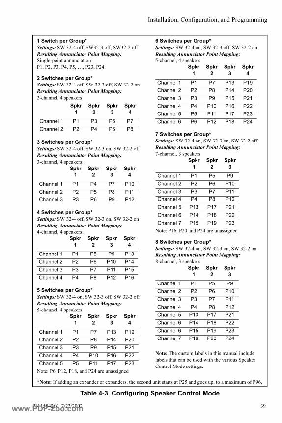
Installation, Configuration, and Programming
PN 15842:K 7/23/2002 39
Table 4-3 Configuring Speaker Control Mode
1 Switch per Group*Settings: SW 32-4 off, SW32-3 off, SW32-2 offResulting Annunciator Point Mapping: Single-point annunciationP1, P2, P3, P4, P5, …, P23, P24.
2 Switches per Group*Settings: SW 32-4 off, SW 32-3 off, SW 32-2 onResulting Annunciator Point Mapping: 2-channel, 4 speakers
3 Switches per Group*Settings: SW 32-4 off, SW 32-3 on, SW 32-2 offResulting Annunciator Point Mapping: 3-channel, 4 speakers:
4 Switches per Group*Settings: SW 32-4 off, SW 32-3 on, SW 32-2 onResulting Annunciator Point Mapping: 4-channel, 4 speakers:
5 Switches per Group*Settings: SW 32-4 on, SW 32-3 off, SW 32-2 offResulting Annunciator Point Mapping: 5-channel, 4 speakers
Note: P6, P12, P18, and P24 are unassigned
6 Switches per Group*Settings: SW 32-4 on, SW 32-3 off, SW 32-2 onResulting Annunciator Point Mapping: 5-channel, 4 speakers
7 Switches per Group*Settings: SW 32-4 on, SW 32-3 on, SW 32-2 offResulting Annunciator Point Mapping: 7-channel, 3 speakers
Note: P16, P20 and P24 are unassigned
8 Switches per Group*Settings: SW 32-4 on, SW 32-3 on, SW 32-2 onResulting Annunciator Point Mapping: 8-channel, 3 speakers
Note: The custom labels in this manual include labels that can be used with the various Speaker Control Mode settings.
Spkr 1
Spkr 2
Spkr 3
Spkr 4
Channel 1 P1 P3 P5 P7Channel 2 P2 P4 P6 P8
Spkr 1
Spkr 2
Spkr 3
Spkr 4
Channel 1 P1 P4 P7 P10Channel 2 P2 P5 P8 P11Channel 3 P3 P6 P9 P12
Spkr 1
Spkr 2
Spkr 3
Spkr 4
Channel 1 P1 P5 P9 P13Channel 2 P2 P6 P10 P14Channel 3 P3 P7 P11 P15Channel 4 P4 P8 P12 P16
Spkr 1
Spkr 2
Spkr 3
Spkr 4
Channel 1 P1 P7 P13 P19Channel 2 P2 P8 P14 P20Channel 3 P3 P9 P15 P21Channel 4 P4 P10 P16 P22Channel 5 P5 P11 P17 P23
Spkr 1
Spkr 2
Spkr 3
Spkr 4
Channel 1 P1 P7 P13 P19Channel 2 P2 P8 P14 P20Channel 3 P3 P9 P15 P21Channel 4 P4 P10 P16 P22Channel 5 P5 P11 P17 P23Channel 6 P6 P12 P18 P24
Spkr 1
Spkr 2
Spkr 3
Channel 1 P1 P5 P9Channel 2 P2 P6 P10Channel 3 P3 P7 P11Channel 4 P4 P8 P12Channel 5 P13 P17 P21Channel 6 P14 P18 P22Channel 7 P15 P19 P23
Spkr 1
Spkr 2
Spkr 3
Channel 1 P1 P5 P9Channel 2 P2 P6 P10Channel 3 P3 P7 P11Channel 4 P4 P8 P12Channel 5 P13 P17 P21Channel 6 P14 P18 P22Channel 6 P15 P19 P23Channel 7 P16 P20 P24
*Note: If adding an expander or expanders, the second unit starts at P25 and goes up, to a maximum of P96.
www.PDF-Zoo.com

Installation, Configuration, and Programming
40 PN 15842:K 7/23/2002
4.13 Setting Address and DIP Switches: ACM-16AT, ACM-32A Annunciator switch settings will vary according to the requirements of your control panel (see this manual’s appendix section).
4.13.1 DIP Switch Summary: ACM-16AT, ACM-32A
4.13.2 Addressing ACM-16AT and ACM-32ASet the address with rotary switches on the back of the annunciator (see Figure 4-4). Turn the arrow with a small flat-head until it points to the correct digit. The rotary switch on the left sets the ‘tens’ digit; the switch on the right sets the ‘ones’ digit.
Up to 32 devices (such as ACMs, LDMs, and AFMs) can be connected to the EIA-485 circuit; the number of addresses available and the number of devices that can answer back depend on the control panel. Refer to your control panel documentation for valid addresses.
Using ACS and a UDACT on the Same Control PanelThe use of a UDACT Universal Alarm Communicator/Transmitter and an Annunciator Control System on the same control panel will alter the assignments of the trouble LEDs on ACS Points 3, 4, 5, 6, 7, and 8. Refer to the UDACT installation manual and the literature for the respective fire alarm control panel for further details.
DIP Switch Function
1 Manual override of control relays (not supported by all control panels; see appendix section)
2, 3 Expanders installed: Set these switches according to how many expanders are installed at the address. See Section 4.13.3 “Configuring Number of Expander Modules”
4 Eight-point Shift (not supported by all control panels; see appendix section)
5 Receive Only (duplicates another annunciator operating at the same address; see Section 3.4 “Receive/Transmit and Receive Only Configuration”)
6 Piezo disabled when set to “ON”7 Switch Inhibit: Set this switch “ON” to disable the point control
switches on the annunciator and prevent them from executing system control functions. When inhibited, the switches will serve as local Lamp Test switches only. In addition, the Acknowledge/Lamp Test switch will function only in a local capacity unrecognized by the system. NOTE: Point-control switches cannot execute system control functions when set to “ON” (Details of function vary according to control panel; see appendix section)
8 Flash inhibit. Disables flashing LEDs and prohibits piezo from sounding.
www.PDF-Zoo.com

Installation, Configuration, and Programming
PN 15842:K 7/23/2002 41
4.13.3 Configuring Number of Expander ModulesIndicate the number of expanders connected to each ACM-16AT/ACM-32A by setting the DIP switch on the end of the annunciator, as shown in Table 4-4.
Note: Switch locations are illustrated in Figure 4-4. To set a DIP switch “ON”, push it towards the green circuit board.
Table 4-4 Configuring Number of Expanders for ACM-16AT and ACM-32A
4.14 Supervising Devices with ACM-16AT, ACM-32AIf using ACM-16AT or ACM-32A, the normally closed Trouble Input on those modules can be used for supervising local power sources or other devices. If employed, all changes in status (to and from the trouble state) will be sent to the control panel in the event of device failure or restoral. If not used, a jumper must be installed across these terminals TB1-6 and TB1-7; without this jumper, the control panel will register a trouble condition. (See Figure 4-19.)
Pin on Annunciator DIP
Switch
Number of expanders installed
None One Two Three
2 off on off on3 off off on on
When not using the trouble input, jumper terminals TB1-6 and TB1-7 together. If an electrical short circuit (jumper) does not exist between terminals TB1-6 and TB1-7, the control panel will register a trouble condition.
Figure 4-19 Using the Trouble Input on ACM-16AT and ACM-32A for Supervising Devices
ACSs
uper
.wm
f
Normally closed trouble
contacts
5 VDC @ 0.5 mA
Trouble Input
TB1 on ACM-16AT, ACM-32ASupervised Device
TB1 on ACM-16AT, ACM-32A
www.PDF-Zoo.com

Installation, Configuration, and Programming
42 PN 15842:K 7/23/2002
4.15 Programming the Control Panel and AnnunciatorsAfter annunciator installation is complete, program the fire alarm control panel to accept the annunciators as explained in the panel's programming guide (see Section 1.2 “Related Documentation” for part numbers).
4.15.1 Selecting LED Colors: ACM-24AT and AEM-24ATSteps to set color of a point-active LED:
1. Power up system according to your control panel instructions.
2. Set DIP switch SW32-1 to “on” to enter programming mode.
3. For each point, press the rubber switch to cycle red/green/yellow and select color that is appropriate for the point’s function (suggested: red for alarm, yellow for trouble, green for active).
4. Set DIP switch SW32-1 back to “off” to return to normal operation.
5. Hold down the Acknowledge/Lamp Test switch to do a lamp test and verify color selections were set correctly.
4.15.2 Selecting LED Colors: ACM-48A & AEM-48ASet SW31 to set color of the point-active LEDs in the right column, and SW30 to set color of the point-active LEDs in the left column. DIP switches are located behind the column of LEDs they control.
To locate these switches on the back of the annunciator, refer to Figure 4-1 and Figure 4-2. To set a DIP switch “ON”, push it towards the green circuit board.
4.16 Testing the Annunciators After programming, fully test the Annunciator Control System to ensure that each switch performs its intended function, that each LED lights in the correct color, and that the annunciators can perform the functions outlined in this manual.
LED
ACM-48A AEM-48A
Switch Position
Switch Position
Switch Position
Switch Position
No color SW30-1 offSW30-2 off
SW31-1 offSW31-2 off
SW25-1 offSW25-2 off
SW26-1 offSW26-2 off
green SW30-1 onSW30-2 off
SW31-1 onSW31-2 off
SW25-1 onSW25-2 off
SW26-1 onSW26-2 off
red SW30-1 offSW30-2 on
SW31-1 offSW31-2 on
SW25-1 offSW25-2 on
SW26-1 offSW26-2 on
yellow SW30-1 onSW30-2 on
SW31-1 onSW31-2 on
SW25-1 onSW25-2 on
SW26-1 onSW26-2 on
www.PDF-Zoo.com
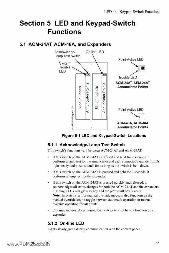
LED and Keypad-Switch Functions
PN 15842:K 7/23/2002 43
Section 5 LED and Keypad-Switch Functions
5.1 ACM-24AT, ACM-48A, and Expanders
Figure 5-1 LED and Keypad-Switch Locations
5.1.1 Acknowledge/Lamp Test SwitchThis switch’s functions vary between ACM-24AT and AEM-24AT:
• If this switch on the ACM-24AT is pressed and held for 2 seconds, it performs a lamp test for the annunciator and each connected expander. LEDs light steady and piezo sounds for as long as the switch is held down.
• If this switch on the AEM-24AT is pressed and held for 2 seconds, it performs a lamp test for the expander.
• If this switch on the ACM-24AT is pressed quickly and released, it acknowledges all status changes for both the ACM-24AT and the expanders. Flashing LEDs will glow steady and the piezo will be silenced. Note: In systems set for manual override mode, it also functions as the manual override key to toggle between automatic operation or manual override operation for all points.
• Pressing and quickly releasing this switch does not have a function on an expander.
5.1.2 On-line LEDLights steady green during communication with the control panel.
ACM-24AT, AEM-24AT Annunciator Points
System Trouble LED
Annu
ncia
tor P
oint
s
Point-Active LED
Trouble LED
Acknowledge/Lamp Test Switch
On-line LED
Annu
ncia
tor P
oint
s
Slid
e-in
Lab
els
Slid
e-in
Lab
els
Point-Active LED
ACM-48A, AEM- 48AAnnunciator Pointsac
m24
-48-
diag
ram
.cdr
www.PDF-Zoo.com

LED and Keypad-Switch Functions
44 PN 15842:K 7/23/2002
5.1.3 System Trouble LEDGlows yellow for all trouble conditions in the system, including points or zones not mapped to the annunciator/expanders. Flashes if communication with control panel is broken.
Note: In systems capable of manual override, this LED may be used to indicate manual override mode.
Note: If annunciator is set for Flash-inhibit, this LED will be on steady for unacknowledged events.
5.1.4 Control SwitchFunctions as a local Lamp Test for the two LEDs dedicated to a point. Control switches can be used to execute such system functions as ACKNOWLEDGE, SIGNAL SILENCE, and SYSTEM RESET. Switches can also be used to control the states of various output circuits. Switches are used to select color of LEDs; see Section 4.15.1 “Selecting LED Colors: ACM-24AT and AEM-24AT”.
Note: If annunciator is set for Switch-inhibit, these switches will not be able to execute system control functions; see appendix section for your fire alarm control panel.
5.1.5 Point-Active LEDOn steady to indicate an active point; after being acknowledged it glows steady until reset.
Note: In Speaker and Telephone Mode, this LED will flash to indicate an active point.
Note: In Speaker Control Mode, this LED works differently; see Section 4.12.4.
5.1.6 Trouble LEDFlashes to indicate a trouble situation. After being acknowledged it glows until reset. If communication with control panel is broken, all trouble LEDs flash.
Note: If annunciator is set for Flash-inhibit, this LED will be on steady for trouble situations.
www.PDF-Zoo.com
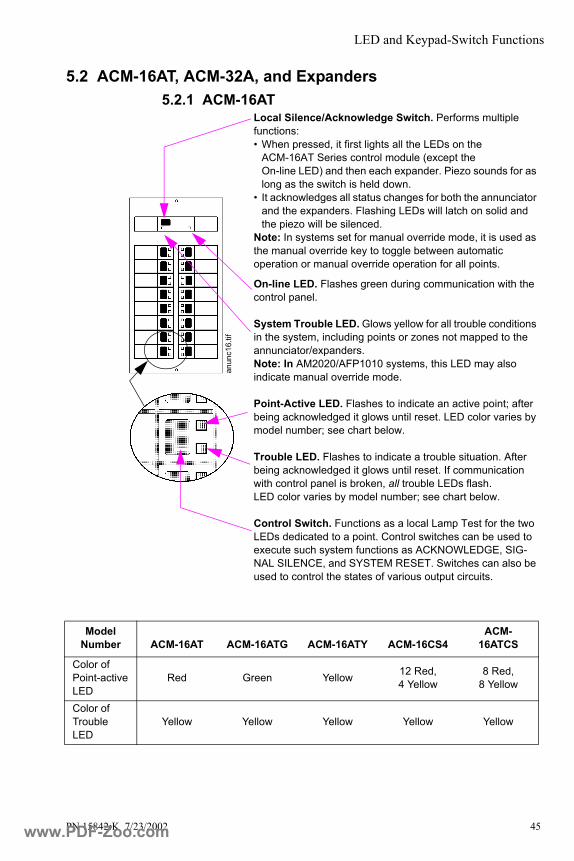
LED and Keypad-Switch Functions
PN 15842:K 7/23/2002 45
5.2 ACM-16AT, ACM-32A, and Expanders5.2.1 ACM-16AT
anun
c16.
tif
Local Silence/Acknowledge Switch. Performs multiple functions: • When pressed, it first lights all the LEDs on the
ACM-16AT Series control module (except the On-line LED) and then each expander. Piezo sounds for as long as the switch is held down.
• It acknowledges all status changes for both the annunciator and the expanders. Flashing LEDs will latch on solid and the piezo will be silenced.
Note: In systems set for manual override mode, it is used as the manual override key to toggle between automatic operation or manual override operation for all points.
On-line LED. Flashes green during communication with the control panel.
System Trouble LED. Glows yellow for all trouble conditions in the system, including points or zones not mapped to the annunciator/expanders. Note: In AM2020/AFP1010 systems, this LED may also indicate manual override mode.
Point-Active LED. Flashes to indicate an active point; after being acknowledged it glows until reset. LED color varies by model number; see chart below.
Trouble LED. Flashes to indicate a trouble situation. After being acknowledged it glows until reset. If communication with control panel is broken, all trouble LEDs flash.LED color varies by model number; see chart below.
Control Switch. Functions as a local Lamp Test for the two LEDs dedicated to a point. Control switches can be used to execute such system functions as ACKNOWLEDGE, SIG-NAL SILENCE, and SYSTEM RESET. Switches can also be used to control the states of various output circuits.
Model Number ACM-16AT ACM-16ATG ACM-16ATY ACM-16CS4
ACM-16ATCS
Color of Point-active LED
Red Green Yellow 12 Red, 4 Yellow
8 Red, 8 Yellow
Color of Trouble LED
Yellow Yellow Yellow Yellow Yellow
www.PDF-Zoo.com

LED and Keypad-Switch Functions
46 PN 15842:K 7/23/2002
5.2.2 AEM-16AT
anun
c16.
tif
Lamp Test Switch. When pressed, it lights all the LEDs on the AEM-16AT Series expander (except the On-line LED) and sounds the piezo for as long as the switch is held down.
Inactive LEDs. These two LEDs are not functional on expander modules.
Point-Active LED. Flashes to indicate an active point; after being acknowledged it glows until reset. LED color varies by model number; see chart below.
Trouble LED. Flashes to indicate a trouble situation. After being acknowledged it glows until reset. If communication with control panel is broken, all trouble LEDs flash.LED color varies by model number; see chart below.
Control SwitchFunctions as a local Lamp Test for the two LEDs dedicated to this point. Control switches can be used to execute such system functions as ACKNOWLEDGE, SIGNAL SILENCE, and SYSTEM RESET. Switches can also be used to control the states of various output circuits.
Model Number AEM-16AT AEM-16ATG AEM-16ATY
Color of Point-active LED Red Green Yellow
Color of Trouble LED Yellow Yellow Yellow
www.PDF-Zoo.com
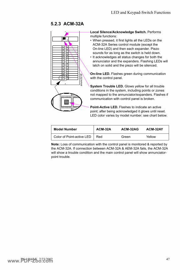
LED and Keypad-Switch Functions
PN 15842:K 7/23/2002 47
5.2.3 ACM-32A
anun
c32.
tif
Local Silence/Acknowledge Switch. Performs multiple functions: • When pressed, it first lights all the LEDs on the
ACM-32A Series control module (except the On-line LED) and then each expander. Piezo sounds for as long as the switch is held down.
• It acknowledges all status changes for both the annunciator and the expanders. Flashing LEDs will latch on solid and the piezo will be silenced.
On-line LED. Flashes green during communication with the control panel.
System Trouble LED. Glows yellow for all trouble conditions in the system, including points or zones not mapped to the annunciator/expanders. Flashes if communication with control panel is broken.
Point-Active LED. Flashes to indicate an active point; after being acknowledged it glows until reset. LED color varies by model number; see chart below.
Note: Loss of communication with the control panel is monitored & reported by the ACM-32A. If connection between ACM-32A & AEM-32A fails, the ACM-32A will show a trouble condition and the main control panel will show annunciator-point trouble.
Model Number ACM-32A ACM-32AG ACM-32AY
Color of Point-active LED Red Green Yellow
www.PDF-Zoo.com

LED and Keypad-Switch Functions
48 PN 15842:K 7/23/2002
5.2.4 AEM-32A
anun
c32.
tif
Lamp Test Switch. When pressed, it lights all the LEDs on the AEM-16AT Series expander (except the On-line LED) and sounds the piezo for as long as the switch is held down.
Inactive LEDs. These two LEDs are not functional on expander modules.
Point-Active LED. Flashes to indicate an active point; after being acknowledged it glows until reset. LED color varies by model number; see chart below.
Note: Loss of communication with the control panel is monitored & reported by the ACM-32A. If connection between ACM-32A & AEM-32A fails, the ACM-32A will show a trouble condition and the main control panel will show annunciator-point trouble.
Model Number AEM-32A AEM-32AG AEM-32AY
Color of Point-active LED Red Green Yellow
www.PDF-Zoo.com
AFP-100 Systems
PN 15842:K 7/23/2002 49
APPENDIX L AFP-100 Systems
L.1 CapabilitiesThe AFP-100 allows annunciators to be programmed by zone or by point. The EIA-485 interface will allow up to 32 annunciators with 64 points at an address, but two-way communications can occur with only one annunciator per address. The other devices must be configured as “Receive Only”.
When the panel is programmed by zone, annunciator address 1 is available, and ACS annunciation displays the 56 software zones of the AFP-100. When the panel is programmed by point, 198 points are available. Annunciator addresses 1, 2, 3, and 4 can be used, but only address 1 is supervised.
The furthest annunciator can be 6,000 feet from the fire alarm control panel (check power limitations).
ACS annunciators on the AFP-100 can not be used for manual control of control modules, bell circuits, or relays (except for global Silence and Drill switches).
L.2 Connecting the EIA-485 CircuitEIA-485 wiring is connected to TB5 of the AFP-100 as shown in the accompanying illustration.
See Section 3.3 “EIA-485 Wiring Specifications” for details and notes about EIA-485 requirements.
L.3 Providing Power to AnnunciatorsThe annunciator’s power supply is connected to +24V non-resettable power; use the middle two pins on TB4 of the AFP-100 as shown in the accompanying illustration. See Section 3.6 “Annunciator Power Requirements & Electrical Ratings” for specifications.
The power run to the annunciator need not contain a Power Supervision Relay because loss of power is inherently supervised through communication loss. This 24 VDC output is power-limited, filtered, and non-resettable.
!
+ -
acs1
00ei
a.cd
r
TB5 on the AFP-100
-+-+-+
+ -
24V UNREG 24VNON-RST 24V RST acs1
00pw
r.cdr
24 VDC
TB4 on the AFP-100
www.PDF-Zoo.com
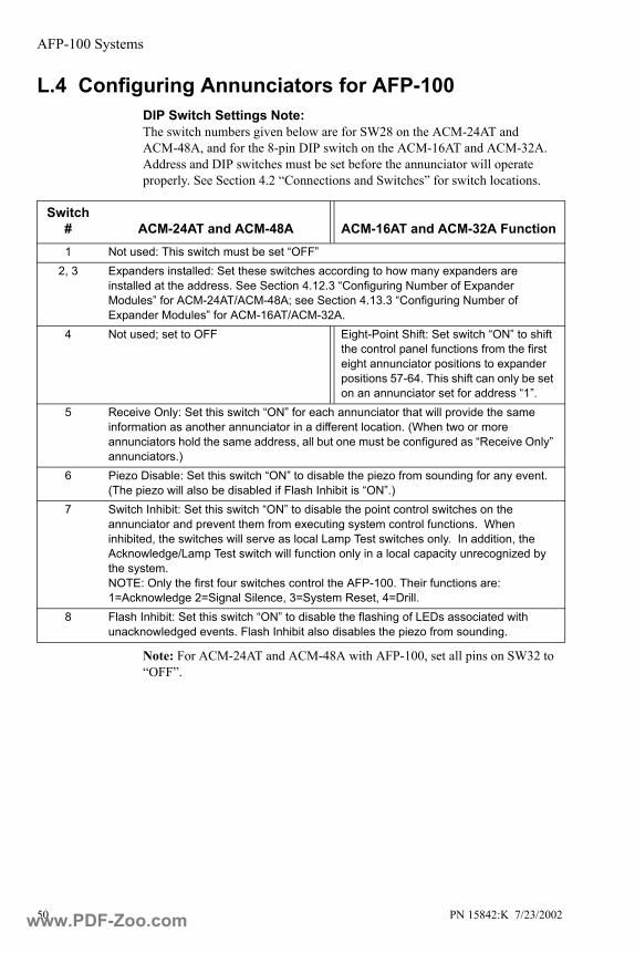
AFP-100 Systems
50 PN 15842:K 7/23/2002
L.4 Configuring Annunciators for AFP-100DIP Switch Settings Note:The switch numbers given below are for SW28 on the ACM-24AT and ACM-48A, and for the 8-pin DIP switch on the ACM-16AT and ACM-32A. Address and DIP switches must be set before the annunciator will operate properly. See Section 4.2 “Connections and Switches” for switch locations.
Note: For ACM-24AT and ACM-48A with AFP-100, set all pins on SW32 to “OFF”.
Switch # ACM-24AT and ACM-48A ACM-16AT and ACM-32A Function1 Not used: This switch must be set “OFF”
2, 3 Expanders installed: Set these switches according to how many expanders are installed at the address. See Section 4.12.3 “Configuring Number of Expander Modules” for ACM-24AT/ACM-48A; see Section 4.13.3 “Configuring Number of Expander Modules” for ACM-16AT/ACM-32A.
4 Not used; set to OFF Eight-Point Shift: Set switch “ON” to shift the control panel functions from the first eight annunciator positions to expander positions 57-64. This shift can only be set on an annunciator set for address “1”.
5 Receive Only: Set this switch “ON” for each annunciator that will provide the same information as another annunciator in a different location. (When two or more annunciators hold the same address, all but one must be configured as “Receive Only” annunciators.)
6 Piezo Disable: Set this switch “ON” to disable the piezo from sounding for any event. (The piezo will also be disabled if Flash Inhibit is “ON”.)
7 Switch Inhibit: Set this switch “ON” to disable the point control switches on the annunciator and prevent them from executing system control functions. When inhibited, the switches will serve as local Lamp Test switches only. In addition, the Acknowledge/Lamp Test switch will function only in a local capacity unrecognized by the system. NOTE: Only the first four switches control the AFP-100. Their functions are: 1=Acknowledge 2=Signal Silence, 3=System Reset, 4=Drill.
8 Flash Inhibit: Set this switch “ON” to disable the flashing of LEDs associated with unacknowledged events. Flash Inhibit also disables the piezo from sounding.
www.PDF-Zoo.com

AFP-200 Systems
PN 15842:K 7/23/2002 51
APPENDIX M AFP-200 Systems
M.1 CapabilitiesACS annunciation displays the 99 software zones of the AFP-200, plus 8 system points, for a total point count of 107. Information is transmitted using only addresses 1 and 2. Up to 32 devices can be driven by the EIA-485 communications output, using two unique addresses with 64 points at an address. Two-way communications can occur with only one annunciator per address; other devices on the same address must be configured as “Receive Only”. The furthest annunciator can be separated from the control panel by no more than 6,000 feet of wire (@16AWG); check specific current requirements for your system.
ACS annunciators on the AFP-200 can not be used for manual control of control modules, bell circuits, or relays (except for global Silence and Drill switches).
M.2 Connecting the EIA-485 CircuitEIA-485 wiring is connected to TB5 of the AFP-200 as shown in the accompanying illustration.
Note:
• Set SW2 on AFP-200 to “ACS” position.
• EIA-485 circuit rated 5.5 VDC max., 60 mA max.
See Section 3.3 “EIA-485 Wiring Specifications” for details and notes about EIA-485 requirements.
M.3 Providing Power to AnnunciatorsThe annunciator’s power supply is connected to +24V non-resettable power; use the middle two pins on TB1 of the AFP-200 as shown in the accompanying illustration. See Section 3.6 “Annunciator Power Requirements & Electrical Ratings” for specifications.
The power run to the annunciator need not contain a Power Supervision Relay because loss of power is inherently supervised through communication loss. This 24 VDC output is power-limited, filtered, and non-resettable.
!
+ -
TB5 TB6
acs2
00ei
a.cd
r
TB5 on the AFP-200
EIA-485 output
-+-+-+
+ -
UNREG+24V
NON-RST+24V
RESET+24V ac
s200
pwr.w
mf
TB1 on the AFP-200
24 VDC
www.PDF-Zoo.com

AFP-200 Systems
52 PN 15842:K 7/23/2002
M.4 Configuring Annunciators for the AFP-200DIP Switch Settings Note:The switch numbers given below are for SW28 on the ACM-24AT and ACM-48A, and for the 8-pin DIP switch on the ACM-16AT and ACM-32A. Address and DIP switches must be set before the annunciator will operate properly. See Section 4.2 “Connections and Switches” for switch locations.
Note: For ACM-24AT and ACM-48A with AFP-200, set all pins on SW32 to “OFF”.
Switch # ACM-24AT and ACM-48A ACM-16AT and ACM-32A Function1 Not used: This switch must be set “OFF”
2, 3 Expanders installed: Set these switches according to how many expanders are installed at the address. See Section 4.12.3 “Configuring Number of Expander Modules” for ACM-24AT/ACM-48A; see Section 4.13.3 “Configuring Number of Expander Modules” for ACM-16AT/ACM-32A.
4 Not used; set to OFF Eight-Point Shift: Set switch “ON” to shift the control panel functions from the first eight annunciator positions to expander positions 57-64. This shift can only be set on an annunciator set for address “1”.
5 Receive Only: Set this switch “ON” for each annunciator that will provide the same information as another annunciator in a different location. (When two or more annunciators hold the same address, all but one must be configured as “Receive Only” annunciators.)
6 Piezo Disable: Set this switch “ON” to disable the piezo from sounding for any event. (The piezo will also be disabled if Flash Inhibit is “ON”.)
7 Switch Inhibit: Set this switch “ON” to disable the point control switches on the annunciator and prevent them from executing system control functions. When inhibited, the switches will serve as local Lamp Test switches only. In addition, the Acknowledge/Lamp Test switch will function only in a local capacity unrecognized by the system. NOTE: Only the first four switches control the AFP-200. Their functions are: 1=Acknowledge 2=Signal Silence, 3=System Reset, 4=Drill.
8 Flash Inhibit: Set this switch “ON” to disable the flashing of LEDs associated with unacknowledged events. Flash Inhibit also disables the piezo from sounding.
www.PDF-Zoo.com
AFP-300/AFP-400
PN 15842:K 7/23/2002 53
APPENDIX N AFP-300/AFP-400
N.1 CapabilitiesWhen installed with an AFP-300/AFP-400, ACS annunciators can be used to annunciate control panel status, addressable devices, panel modules, and software zones. The fire alarm control panel uses ACS Annunciator addresses 1 through 19 (1 through 10 when employing a UDACT). Up to 32 devices can be driven by the EIA-485 communications output, all addresses combined, with up to 64 points to an address. Two-way communications can occur with only one annunciator per address; other devices on the same address must be configured as “Receive Only”.
The panel annunciation points are divided into nine groups of 64 points. Each group can be assigned to one or more of the 19 annunciator addresses supported by the AFP-300/AFP-400. See the AFP-300/AFP-400 Programming Manual for assignment details.
N.2 Connecting the EIA-485 CircuitEIA-485 wiring is connected to TB4 of the AFP-300/AFP-400 as shown in the accompanying illustration.
See Section 3.3 “EIA-485 Wiring Specifications” for details and notes about EIA-485 requirements.
N.3 Providing Power to AnnunciatorsAFP-300/AFP-400 panels use Main Power Supply MPS-400. The annunciator’s power supply is connected to either of the MPS-400’s two non-resettable power supplies: TB2 Terminals 1(+) and 2 (-) or TB2 Terminals 3 (+) and 4(-), as shown in the accompanying illustration. No more than 1.25A can be drawn from these power-limited terminals in standby or alarm.
See Section 3.6 “Annunciator Power Requirements & Electrical Ratings” for specifications.
The power run to the annunciator need not contain a Power Supervision Relay because loss of power is inherently supervised through communication loss. This 24 VDC output is power-limited, filtered, and non-resettable.
!
-+
+ -
acs4
00ei
a.cd
r
TB4 on AFP-300/AFP-400
+ - + -
-+-+-+ acs4
00pw
r.cdr
TB2 on the MPS-400
24 VDCA B
www.PDF-Zoo.com
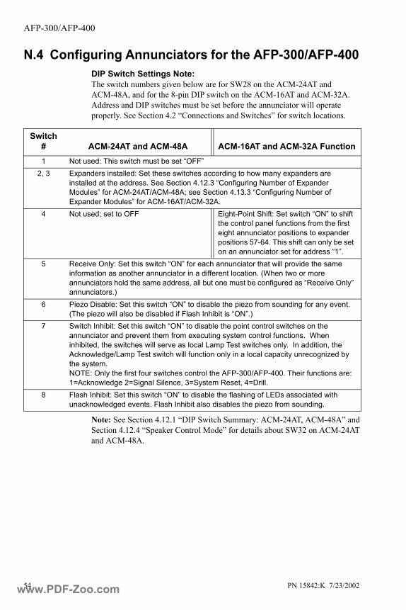
AFP-300/AFP-400
54 PN 15842:K 7/23/2002
N.4 Configuring Annunciators for the AFP-300/AFP-400DIP Switch Settings Note:The switch numbers given below are for SW28 on the ACM-24AT and ACM-48A, and for the 8-pin DIP switch on the ACM-16AT and ACM-32A. Address and DIP switches must be set before the annunciator will operate properly. See Section 4.2 “Connections and Switches” for switch locations.
Note: See Section 4.12.1 “DIP Switch Summary: ACM-24AT, ACM-48A” and Section 4.12.4 “Speaker Control Mode” for details about SW32 on ACM-24AT and ACM-48A.
Switch # ACM-24AT and ACM-48A ACM-16AT and ACM-32A Function1 Not used: This switch must be set “OFF”
2, 3 Expanders installed: Set these switches according to how many expanders are installed at the address. See Section 4.12.3 “Configuring Number of Expander Modules” for ACM-24AT/ACM-48A; see Section 4.13.3 “Configuring Number of Expander Modules” for ACM-16AT/ACM-32A.
4 Not used; set to OFF Eight-Point Shift: Set switch “ON” to shift the control panel functions from the first eight annunciator positions to expander positions 57-64. This shift can only be set on an annunciator set for address “1”.
5 Receive Only: Set this switch “ON” for each annunciator that will provide the same information as another annunciator in a different location. (When two or more annunciators hold the same address, all but one must be configured as “Receive Only” annunciators.)
6 Piezo Disable: Set this switch “ON” to disable the piezo from sounding for any event. (The piezo will also be disabled if Flash Inhibit is “ON”.)
7 Switch Inhibit: Set this switch “ON” to disable the point control switches on the annunciator and prevent them from executing system control functions. When inhibited, the switches will serve as local Lamp Test switches only. In addition, the Acknowledge/Lamp Test switch will function only in a local capacity unrecognized by the system. NOTE: Only the first four switches control the AFP-300/AFP-400. Their functions are: 1=Acknowledge 2=Signal Silence, 3=System Reset, 4=Drill.
8 Flash Inhibit: Set this switch “ON” to disable the flashing of LEDs associated with unacknowledged events. Flash Inhibit also disables the piezo from sounding.
www.PDF-Zoo.com

AFP-300/AFP-400
PN 15842:K 7/23/2002 55
N.5 System and Point Annunciation The control panel's annunciation points are divided into nine ACS Selection Groups of 64 points. Table N-1, which follows, summarizes the ACS Selection Groups and what an annunciator displays if a group is selected. The AFP-300/AFP-400 installation manual provides a complete listing of the points within the ACS Selection Groups and instructions on programming the panel for addressable annunciators.
Note: Annunciators configured for point annunciation:
• Do not respond to any status change that is not within its ACS Selection Group. This includes system alarm or system trouble.
• Do mask status changes for point number 1 of the start address selection.
• Do not respond to System Reset, Acknowledge, or Alarm Silence.
• Do not use the battery saving feature (100 mA battery load)
ACS Selection Group Annunciator Display
1 Control Panel Status and Zones 1-56
2 Zones 57-99, NAC Ckts 1-4 and 16 Special Zones
3 Intelligent Modules 101 to 164
4 Intelligent Modules 201-264 (AFP-400 only)
5 Intelligent Modules 165-196 and 265-296 (AFP-400 only)
6 Detectors 101 to 164 on SLC loop 1
7 Detectors 201-264 on SLC loop 2 (AFP-400 only)
8 Detectors 165-196 and 265-296 (AFP-400 only)
9 Panel Output Circuit Modules (64 points)
A Programmable annunciator group A; requires VeriFire™ 400 software to program
B Programmable annunciator group B; requires VeriFire™ 400 software to program
* or 0 Annunciator Not Installed At Address
Table N-1 Zone and Point Mapping With AFP-300/AFP-400
www.PDF-Zoo.com
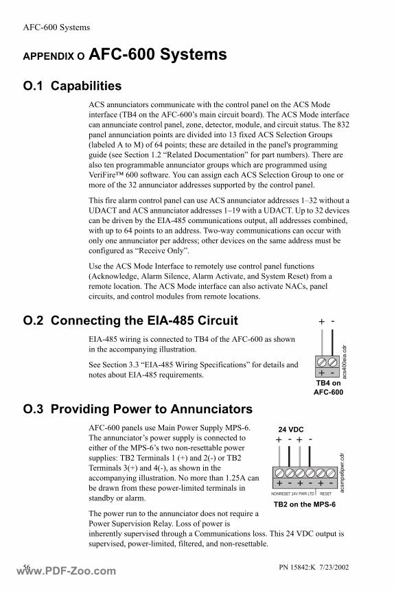
AFC-600 Systems
56 PN 15842:K 7/23/2002
APPENDIX O AFC-600 Systems
O.1 CapabilitiesACS annunciators communicate with the control panel on the ACS Mode interface (TB4 on the AFC-600’s main circuit board). The ACS Mode interface can annunciate control panel, zone, detector, module, and circuit status. The 832 panel annunciation points are divided into 13 fixed ACS Selection Groups (labeled A to M) of 64 points; these are detailed in the panel's programming guide (see Section 1.2 “Related Documentation” for part numbers). There are also ten programmable annunciator groups which are programmed using VeriFire™ 600 software. You can assign each ACS Selection Group to one or more of the 32 annunciator addresses supported by the control panel.
This fire alarm control panel can use ACS annunciator addresses 1–32 without a UDACT and ACS annunciator addresses 1–19 with a UDACT. Up to 32 devices can be driven by the EIA-485 communications output, all addresses combined, with up to 64 points to an address. Two-way communications can occur with only one annunciator per address; other devices on the same address must be configured as “Receive Only”.
Use the ACS Mode Interface to remotely use control panel functions (Acknowledge, Alarm Silence, Alarm Activate, and System Reset) from a remote location. The ACS Mode interface can also activate NACs, panel circuits, and control modules from remote locations.
O.2 Connecting the EIA-485 CircuitEIA-485 wiring is connected to TB4 of the AFC-600 as shown in the accompanying illustration.
See Section 3.3 “EIA-485 Wiring Specifications” for details and notes about EIA-485 requirements.
O.3 Providing Power to AnnunciatorsAFC-600 panels use Main Power Supply MPS-6. The annunciator’s power supply is connected to either of the MPS-6’s two non-resettable power supplies: TB2 Terminals 1 (+) and 2(-) or TB2 Terminals 3(+) and 4(-), as shown in the accompanying illustration. No more than 1.25A can be drawn from these power-limited terminals in standby or alarm.
The power run to the annunciator does not require a Power Supervision Relay. Loss of power is inherently supervised through a Communications loss. This 24 VDC output is supervised, power-limited, filtered, and non-resettable.
-+
+ -
acs4
00ei
a.cd
r
TB4 on AFC-600
+ -+ -
-+-+-+NONRESET 24V PWR LTD RESET ac
smps
6pw
r.cdr
TB2 on the MPS-6
24 VDC
www.PDF-Zoo.com

AFC-600 Systems
PN 15842:K 7/23/2002 57
O.4 Configuring Annunciators for the AFC-600DIP Switch Settings Note:The switch numbers given below are for SW28 on the ACM-24AT and ACM-48A, and for the 8-pin DIP switch on the ACM-16AT and ACM-32A. Address and DIP switches must be set before the annunciator will operate properly. See Section 4.2 “Connections and Switches” for switch locations.
Note: See Section 4.12.1 “DIP Switch Summary: ACM-24AT, ACM-48A” and Section 4.12.4 “Speaker Control Mode” for details about SW32 on ACM-24AT and ACM-48A.
O.5 System and Point Annunciation The control panel's annunciation points are divided into 13 ACS Selection Groups of 64 points. Table O-1, which follows, summarizes the ACS Selection Groups and what an annunciator displays if a group is selected. This fire alarm control panel's Programming Manual provides a complete listing of the points within the ACS Selection Groups and instructions on programming the panel for addressable annunciators.
Switch # ACM-24AT and ACM-48A ACM-16AT and ACM-32A Function1 Not used: This switch must be set “OFF”
2, 3 Expanders installed: Set these switches according to how many expanders are installed at the address. See Section 4.12.3 “Configuring Number of Expander Modules” for ACM-24AT/ACM-48A; see Section 4.13.3 “Configuring Number of Expander Modules” for ACM-16AT/ACM-32A.
4 Not used; set to OFF Eight-Point Shift: Set switch “ON” to shift the control panel functions from the first eight annunciator positions to expander positions 57-64. This shift can only be set on an annunciator set for address “1”.
5 Receive Only: Set this switch “ON” for each annunciator that will provide the same information as another annunciator in a different location. (When two or more annunciators hold the same address, all but one must be configured as “Receive Only” annunciators.)
6 Piezo Disable: Set this switch “ON” to disable the piezo from sounding for any event. (The piezo will also be disabled if Flash Inhibit is “ON”.)
7 Switch Inhibit: Set this switch “ON” to disable the point control switches on the annunciator and prevent them from executing system control functions. When inhibited, the switches will serve as local Lamp Test switches only. In addition, the Acknowledge/Lamp Test switch will function only in a local capacity unrecognized by the system. NOTE: Only the first four switches control the AFC-600. Their functions are: 1=Acknowledge 2=Signal Silence, 3=System Reset, 4=Drill.
8 Flash Inhibit: Set this switch “ON” to disable the flashing of LEDs associated with unacknowledged events. Flash Inhibit also disables the piezo from sounding.
www.PDF-Zoo.com

AFC-600 Systems
58 PN 15842:K 7/23/2002
*Note: VeriFire™ 600 is required to define Programmable Annunciator Groups.
Note: Annunciators configured for point annunciation:
• Do not respond to any status change, including system alarm or system trouble, that is not within its ACS Selection Group.
• Do mask status changes for point number 1 of the start address selection.• Do not respond to System Reset, Acknowledge, or Alarm Silence.• Do not use the battery saving feature (100 mA battery load).
ACS Selection Group Annunciator Display
A 8 Systems points + Zones 1-56B Zones 57-99, 8 F zones, 4 NACC Loop 1, Modules 1-64D Loop 2, Modules 1-64E Loop 1, Modules 65-128F Loop 2, Modules 65-128G Loop 1 - Modules 129-159, 2 unused points
Loop 2 - Modules 129-159, 2 unused pointsH Loop 1, Detectors 1-64I Loop 2, Detectors 1-64J Loop 1, Detectors 65-128K Loop 2, Detectors 65-128L Loop 1 - Detectors 129-159, 2 unused points
Loop 2 - Detectors 129-159, 2 unused pointsM Panel circuits 1-1 to 8-8 (64)1 Programmable Annunciator Group #1 *2 Programmable Annunciator Group #2 *3 Programmable Annunciator Group #3 *4 Programmable Annunciator Group #4 *5 Programmable Annunciator Group #5 *6 Programmable Annunciator Group #6 *7 Programmable Annunciator Group #7 *8 Programmable Annunciator Group #8 *9 Programmable Annunciator Group #9 *0 Programmable Annunciator Group #10 *
Table O-1 ACS Selection Groups and the Annunciator Display
www.PDF-Zoo.com
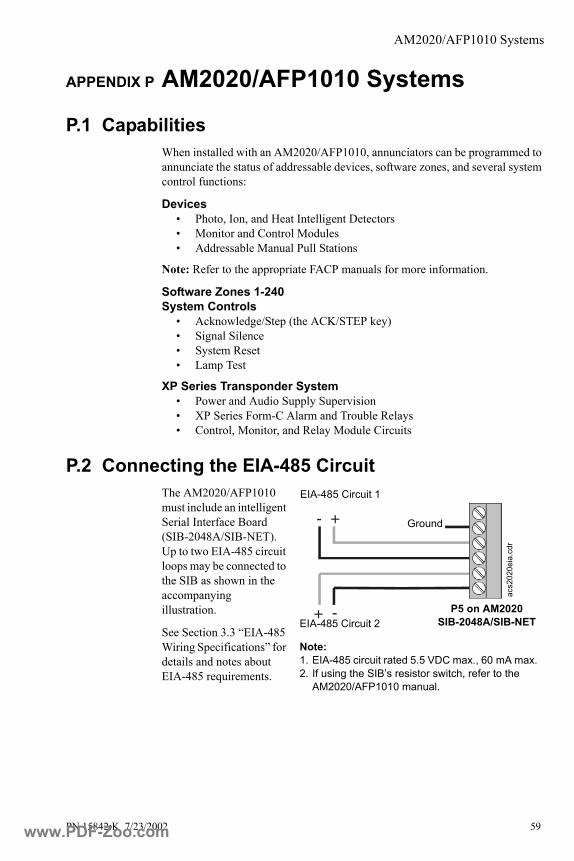
AM2020/AFP1010 Systems
PN 15842:K 7/23/2002 59
APPENDIX P AM2020/AFP1010 Systems
P.1 CapabilitiesWhen installed with an AM2020/AFP1010, annunciators can be programmed to annunciate the status of addressable devices, software zones, and several system control functions:
Devices• Photo, Ion, and Heat Intelligent Detectors• Monitor and Control Modules• Addressable Manual Pull Stations
Note: Refer to the appropriate FACP manuals for more information.
Software Zones 1-240System Controls
• Acknowledge/Step (the ACK/STEP key)• Signal Silence• System Reset• Lamp Test
XP Series Transponder System• Power and Audio Supply Supervision• XP Series Form-C Alarm and Trouble Relays• Control, Monitor, and Relay Module Circuits
P.2 Connecting the EIA-485 CircuitThe AM2020/AFP1010 must include an intelligent Serial Interface Board (SIB-2048A/SIB-NET). Up to two EIA-485 circuit loops may be connected to the SIB as shown in the accompanying illustration.
See Section 3.3 “EIA-485 Wiring Specifications” for details and notes about EIA-485 requirements.
+ -
+ -
acs2
020e
ia.c
dr
Ground
P5 on AM2020 SIB-2048A/SIB-NET
EIA-485 Circuit 1
EIA-485 Circuit 2
Note: 1. EIA-485 circuit rated 5.5 VDC max., 60 mA max. 2. If using the SIB’s resistor switch, refer to the
AM2020/AFP1010 manual.
www.PDF-Zoo.com
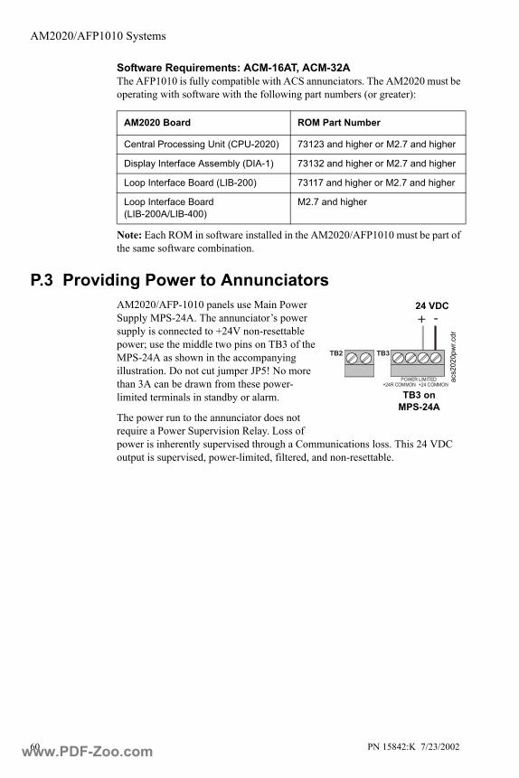
AM2020/AFP1010 Systems
60 PN 15842:K 7/23/2002
Software Requirements: ACM-16AT, ACM-32AThe AFP1010 is fully compatible with ACS annunciators. The AM2020 must be operating with software with the following part numbers (or greater):
Note: Each ROM in software installed in the AM2020/AFP1010 must be part of the same software combination.
P.3 Providing Power to Annunciators AM2020/AFP-1010 panels use Main Power Supply MPS-24A. The annunciator’s power supply is connected to +24V non-resettable power; use the middle two pins on TB3 of the MPS-24A as shown in the accompanying illustration. Do not cut jumper JP5! No more than 3A can be drawn from these power-limited terminals in standby or alarm.
The power run to the annunciator does not require a Power Supervision Relay. Loss of power is inherently supervised through a Communications loss. This 24 VDC output is supervised, power-limited, filtered, and non-resettable.
AM2020 Board ROM Part Number
Central Processing Unit (CPU-2020) 73123 and higher or M2.7 and higher
Display Interface Assembly (DIA-1) 73132 and higher or M2.7 and higher
Loop Interface Board (LIB-200) 73117 and higher or M2.7 and higher
Loop Interface Board (LIB-200A/LIB-400)
M2.7 and higher
TB2 TB3
+ -
POWER LIMITED+24R COMMON +24 COMMON
acs2
020p
wr.c
dr
24 VDC
TB3 on MPS-24A
www.PDF-Zoo.com

AM2020/AFP1010 Systems
PN 15842:K 7/23/2002 61
P.4 Programming the AM2020/AFP1010 for Remote Annunciation
Annunciator points must be programmed from the AM2020/AFP1010 before the annunciators will function. The AM2020/AFP1010 employ the following format for annunciator points:
Note: To program the annunciators into AM2020/AFP1010 memory, and to map system points and software zones to annunciator points, refer to the AM2020/AFP1010 Manual.
Note: When using the NCA to annunciate points on the AM2020/AFP1010 over the network, enable state reporting in the AM2020/AFP1010 panel for control module points and “NONA”/”NOA” module points; refer to the NCA Manual for instructions.
A(xx) P(yy)
Annunciator addressIn the range of 1-32, as set on the annunciator’s rotary decimal switches.
Annunciator Points per Module
ACM-24AT, Points 1-24
First AEM-24AT, Points 25-48
Second AEM-24AT, Points 49-64
Note: Points 65-72 are not used
ACM-48A, Points 1-48
AEM-48A Points 49-64 Note: Points 65-96 are not used
ACM-16AT, Points 1-16
First AEM-16AT, Points 17-32
Second AEM-16AT, Points 33-48
Third AEM-16AT, Points 49-64
ACM-32A, Points 1-32
AEM-32A, Points 33-64
www.PDF-Zoo.com

AM2020/AFP1010 Systems
62 PN 15842:K 7/23/2002
P.5 Configuring Annunciators for AM2020/AFP1010DIP Switch Settings Note:The switch numbers given below are for SW28 on the ACM-24AT and ACM-48A, and for the 8-pin DIP switch on the ACM-16AT and ACM-32A. Address and DIP switches must be set before the annunciator will operate properly. See Section 4.2 “Connections and Switches” for switch locations.
Note: See Section 4.12.1 “DIP Switch Summary: ACM-24AT, ACM-48A” and Section 4.12.4 “Speaker Control Mode” for details about SW32 on ACM-24AT and ACM-48A.
Switch # ACM-24AT and ACM-48A ACM-16AT and ACM-32A Function1 Manual override: Set “ON” when the annunciator is used for manual override of control
relays.2, 3 Expanders installed: Set these switches according to how many expanders are
installed at the address. See Section 4.12.3 “Configuring Number of Expander Modules” for ACM-24AT/ACM-48A; see Section 4.13.3 “Configuring Number of Expander Modules” for ACM-16AT/ACM-32A.
4 Not used; set to OFF Eight-Point Shift: Always set this switch “OFF” in AM2020/AFP1010 systems.
5 Receive Only: Set this switch “ON” for each annunciator that will provide the same information as another annunciator in a different location. (When two or more annunciators hold the same address, all but one must be configured as “Receive Only” annunciators.)
6 Piezo Disable: Set this switch “ON” to disable the piezo from sounding for any event. (The piezo will also be disabled if Flash Inhibit is “ON”.)
7 Switch Inhibit: Set this switch “ON” to disable the point control switches on the annunciator and prevent them from executing system control functions. When inhibited, the switches will serve as local Lamp Test switches only. In addition, the Acknowledge/Lamp Test switch will function only in a local capacity unrecognized by the system.
8 Flash Inhibit: Set this switch “ON” to disable the flashing of LEDs associated with unacknowledged events. Flash Inhibit also disables the piezo from sounding.
www.PDF-Zoo.com
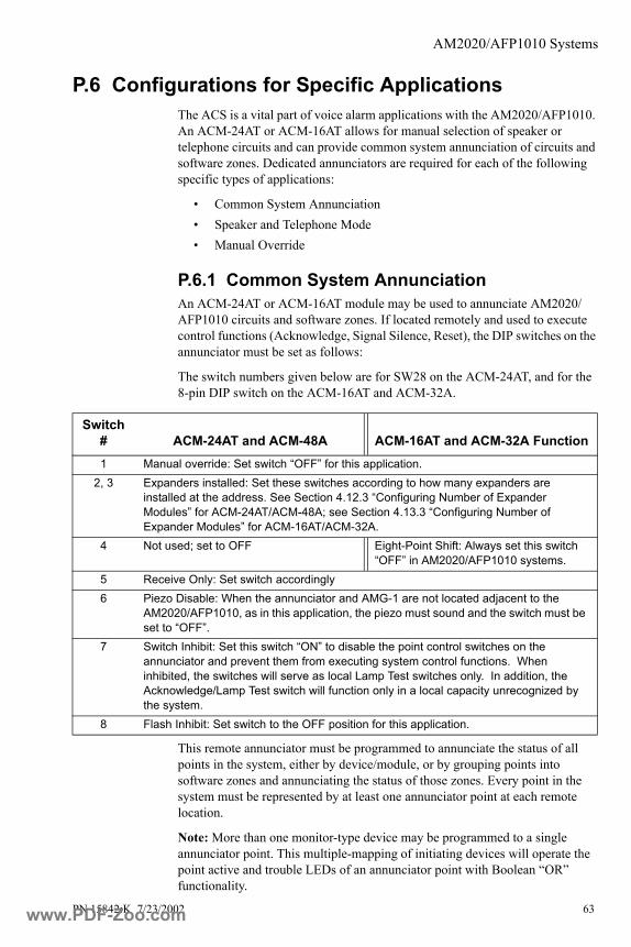
AM2020/AFP1010 Systems
PN 15842:K 7/23/2002 63
P.6 Configurations for Specific ApplicationsThe ACS is a vital part of voice alarm applications with the AM2020/AFP1010. An ACM-24AT or ACM-16AT allows for manual selection of speaker or telephone circuits and can provide common system annunciation of circuits and software zones. Dedicated annunciators are required for each of the following specific types of applications:
• Common System Annunciation• Speaker and Telephone Mode• Manual Override
P.6.1 Common System AnnunciationAn ACM-24AT or ACM-16AT module may be used to annunciate AM2020/AFP1010 circuits and software zones. If located remotely and used to execute control functions (Acknowledge, Signal Silence, Reset), the DIP switches on the annunciator must be set as follows:
The switch numbers given below are for SW28 on the ACM-24AT, and for the 8-pin DIP switch on the ACM-16AT and ACM-32A.
This remote annunciator must be programmed to annunciate the status of all points in the system, either by device/module, or by grouping points into software zones and annunciating the status of those zones. Every point in the system must be represented by at least one annunciator point at each remote location.
Note: More than one monitor-type device may be programmed to a single annunciator point. This multiple-mapping of initiating devices will operate the point active and trouble LEDs of an annunciator point with Boolean “OR” functionality.
Switch # ACM-24AT and ACM-48A ACM-16AT and ACM-32A Function1 Manual override: Set switch “OFF” for this application.
2, 3 Expanders installed: Set these switches according to how many expanders are installed at the address. See Section 4.12.3 “Configuring Number of Expander Modules” for ACM-24AT/ACM-48A; see Section 4.13.3 “Configuring Number of Expander Modules” for ACM-16AT/ACM-32A.
4 Not used; set to OFF Eight-Point Shift: Always set this switch “OFF” in AM2020/AFP1010 systems.
5 Receive Only: Set switch accordingly6 Piezo Disable: When the annunciator and AMG-1 are not located adjacent to the
AM2020/AFP1010, as in this application, the piezo must sound and the switch must be set to “OFF”.
7 Switch Inhibit: Set this switch “ON” to disable the point control switches on the annunciator and prevent them from executing system control functions. When inhibited, the switches will serve as local Lamp Test switches only. In addition, the Acknowledge/Lamp Test switch will function only in a local capacity unrecognized by the system.
8 Flash Inhibit: Set switch to the OFF position for this application.
www.PDF-Zoo.com

AM2020/AFP1010 Systems
64 PN 15842:K 7/23/2002
P.6.2 Speaker and Telephone Mode To execute audio functions, use an ACM-24AT or ACM-16AT set to address 1. This annunciator (and any expanders) must be installed adjacent to the AMG-1 and points assigned for AMG control cannot be used for common system annunciation, or for the manual control of circuits and relays. Telephone points can be mapped to unused points on this annunciator or on another ACM-24AT or ACM-16AT annunciator for the control of telephone circuits. Set the DIP switches as follows.The switch numbers given below are for SW28 on the ACM-24AT, and for the 8-pin DIP switch on the ACM-16AT.
Dip Switch:
When configured as outlined in Speaker and Telephone Mode, the ACM-24AT or ACM-16AT will function as follows:
• All new conditions (except telephone call-in) The piezo will not sound and LEDs will not flash.
• Telephone call-in: The piezo will sound and both the point active and trouble LEDs for the respective telephone point will flash. Pressing the telephone point switch on the ACM-24AT or ACM-16AT will silence the piezo and illuminate LEDs steadily. The AM2020/AFP1010 will indicate telephone circuit connection by turning off the trouble LED.
P.6.3 Manual OverrideManual Override allows the on/off control of relays to be placed under sole control of the annunciator switches. When Dip Switch 1 is ON, and the Manual Override key has been pressed on the ACM-24AT or ACM-16AT, the annunciator is in Manual Override mode, and the yellow override LED is ON. Pressing the key again returns the annunciator to automatic mode. In manual mode, automatic (control-by-event) commands from the AM2020/AFP1010 are ignored, and relays may be switched on/off only from the annunciator switches. In automatic mode, the relays may be switched by either the AM2020/AFP1010 or the annunciator switches.
Switch # ACM-24AT Function ACM-16AT Function1 Manual override: Set switch “OFF” for this application
2, 3 Expanders installed: Set these switches according to how many expanders are installed at the address. See Section 4.12.3 “Configuring Number of Expander Modules” for ACM-24AT/ACM-48A; see Section 4.13.3 “Configuring Number of Expander Modules” for ACM-16AT/ACM-32A.
4 Not used; set to OFF Eight-Point Shift: Always set this switch “OFF” in AM2020/AFP1010 systems.
5 Receive Only: Set switch “OFF” for this application.6 Piezo Disable: Set this switch “ON” for this application unless the annunciator and
AMG-1 are not located adjacent to the AM2020/AFP1010. In that case, the piezo must sound and the switch must be set to “OFF”.
7 Switch Inhibit: Set this switch”OFF” for this application.8 Flash Inhibit: Set this switch “ON” for this application.
www.PDF-Zoo.com

AM2020/AFP1010 Systems
PN 15842:K 7/23/2002 65
When in manual override mode, all points displayed on the ACM-24AT or ACM-16AT and all its expanders will ignore subsequent Control-by-Event (CBE) commands from the panel.
Manual Override Mode can be entered by pressing the Manual Override switch on the ACM-24AT or ACM-16AT module (Use special slide-in label).
• The Manual LED on the ACM-24AT or ACM-16AT module will illuminate steadily.
• The AM2020/AFP1010 will register an ANNUNCIATOR TROUBLE condition.
• The state of the each annunciator point will remain the same as before.
• The output circuits can now be controlled via their point switches.
The AM2020/AFP1010 Control-By-Event will not override the manual control setting of the ACM-24AT or ACM-16AT module. To return the annunciator to Automatic Mode, press the Manual Override switch again (toggle action). Set the DIP switches on a Manual Override annunciator as follows.The switch numbers given below are for SW28 on the ACM-24AT, and for the 8-pin DIP switch on the ACM-16AT.
Dip Switch:
!
Switch # ACM-24AT Function ACM-16AT Function1 Manual override: Set “ON” for this application.
2, 3 Expanders installed: Set these switches according to how many expanders are installed at the address. See Section 4.12.3 “Configuring Number of Expander Modules” for ACM-24AT/ACM-48A; see Section 4.13.3 “Configuring Number of Expander Modules” for ACM-16AT/ACM-32A.
4 Not used; set to OFF Eight-Point Shift: Always set this switch “OFF” in AM2020/AFP1010 systems.
5 Receive Only: Set this switch “OFF” for this application.6 Piezo Disable: Set this switch “ON” for this application unless the annunciator and
AMG-1 are not located adjacent to the AM2020/AFP1010. In that case, the piezo must sound and the switch must be set to “OFF”.
7 Switch Inhibit: Set this switch “OFF” for this application.8 Flash Inhibit: Set this switch “OFF” for this application.
www.PDF-Zoo.com
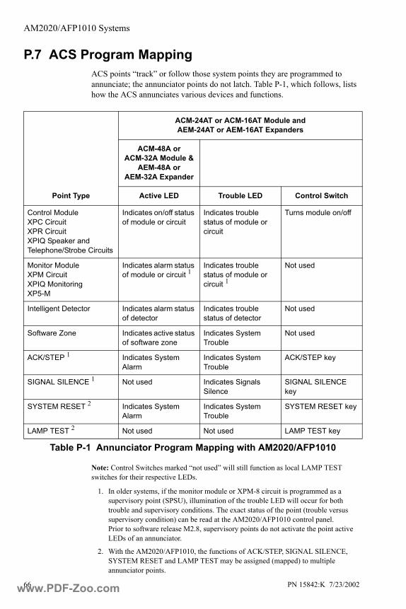
AM2020/AFP1010 Systems
66 PN 15842:K 7/23/2002
P.7 ACS Program MappingACS points “track” or follow those system points they are programmed to annunciate; the annunciator points do not latch. Table P-1, which follows, lists how the ACS annunciates various devices and functions.
Note: Control Switches marked “not used” will still function as local LAMP TEST switches for their respective LEDs.
1. In older systems, if the monitor module or XPM-8 circuit is programmed as a supervisory point (SPSU), illumination of the trouble LED will occur for both trouble and supervisory conditions. The exact status of the point (trouble versus supervisory condition) can be read at the AM2020/AFP1010 control panel.Prior to software release M2.8, supervisory points do not activate the point active LEDs of an annunciator.
2. With the AM2020/AFP1010, the functions of ACK/STEP, SIGNAL SILENCE, SYSTEM RESET and LAMP TEST may be assigned (mapped) to multiple annunciator points.
Point Type
ACM-24AT or ACM-16AT Module and AEM-24AT or AEM-16AT Expanders
ACM-48A or ACM-32A Module &
AEM-48A or AEM-32A Expander
Active LED Trouble LED Control Switch
Control Module XPC CircuitXPR CircuitXPIQ Speaker and Telephone/Strobe Circuits
Indicates on/off status of module or circuit
Indicates trouble status of module or circuit
Turns module on/off
Monitor Module XPM CircuitXPIQ MonitoringXP5-M
Indicates alarm status of module or circuit 1
Indicates trouble status of module or circuit 1
Not used
Intelligent Detector Indicates alarm status of detector
Indicates trouble status of detector
Not used
Software Zone Indicates active status of software zone
Indicates System Trouble
Not used
ACK/STEP 1 Indicates System Alarm
Indicates System Trouble
ACK/STEP key
SIGNAL SILENCE 1 Not used Indicates Signals Silence
SIGNAL SILENCE key
SYSTEM RESET 2 Indicates System Alarm
Indicates System Trouble
SYSTEM RESET key
LAMP TEST 2 Not used Not used LAMP TEST key
Table P-1 Annunciator Program Mapping with AM2020/AFP1010
www.PDF-Zoo.com
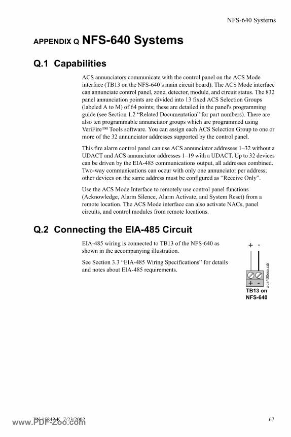
NFS-640 Systems
PN 15842:K 7/23/2002 67
APPENDIX Q NFS-640 Systems
Q.1 CapabilitiesACS annunciators communicate with the control panel on the ACS Mode interface (TB13 on the NFS-640’s main circuit board). The ACS Mode interface can annunciate control panel, zone, detector, module, and circuit status. The 832 panel annunciation points are divided into 13 fixed ACS Selection Groups (labeled A to M) of 64 points; these are detailed in the panel's programming guide (see Section 1.2 “Related Documentation” for part numbers). There are also ten programmable annunciator groups which are programmed using VeriFire™ Tools software. You can assign each ACS Selection Group to one or more of the 32 annunciator addresses supported by the control panel.
This fire alarm control panel can use ACS annunciator addresses 1–32 without a UDACT and ACS annunciator addresses 1–19 with a UDACT. Up to 32 devices can be driven by the EIA-485 communications output, all addresses combined. Two-way communications can occur with only one annunciator per address; other devices on the same address must be configured as “Receive Only”.
Use the ACS Mode Interface to remotely use control panel functions (Acknowledge, Alarm Silence, Alarm Activate, and System Reset) from a remote location. The ACS Mode interface can also activate NACs, panel circuits, and control modules from remote locations.
Q.2 Connecting the EIA-485 CircuitEIA-485 wiring is connected to TB13 of the NFS-640 as shown in the accompanying illustration.
See Section 3.3 “EIA-485 Wiring Specifications” for details and notes about EIA-485 requirements.
-+
+ -
acs4
00ei
a.cd
r
TB13 on NFS-640
www.PDF-Zoo.com

NFS-640 Systems
68 PN 15842:K 7/23/2002
Q.3 Providing Power to AnnunciatorsNFS-640 panels have an integral on-board power supply. The annunciator’s power supply is connected to TB7 of the control panel as shown in the accompanying illustration. No more than 1.25A can be drawn from these power-limited terminals in standby or alarm.
The power run to the annunciator does not require a Power Supervision Relay. Loss of power is inherently supervised through a Communications loss. This 24 VDC output is supervised, power-limited, filtered, and non-resettable.
TB7
-+-+
-+
acs6
40pw
r.cdr
24 VDC
TB7 on NFS-640
www.PDF-Zoo.com
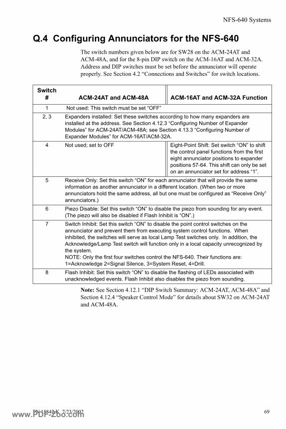
NFS-640 Systems
PN 15842:K 7/23/2002 69
Q.4 Configuring Annunciators for the NFS-640The switch numbers given below are for SW28 on the ACM-24AT and ACM-48A, and for the 8-pin DIP switch on the ACM-16AT and ACM-32A. Address and DIP switches must be set before the annunciator will operate properly. See Section 4.2 “Connections and Switches” for switch locations.
Note: See Section 4.12.1 “DIP Switch Summary: ACM-24AT, ACM-48A” and Section 4.12.4 “Speaker Control Mode” for details about SW32 on ACM-24AT and ACM-48A.
Switch # ACM-24AT and ACM-48A ACM-16AT and ACM-32A Function1 Not used: This switch must be set “OFF”
2, 3 Expanders installed: Set these switches according to how many expanders are installed at the address. See Section 4.12.3 “Configuring Number of Expander Modules” for ACM-24AT/ACM-48A; see Section 4.13.3 “Configuring Number of Expander Modules” for ACM-16AT/ACM-32A.
4 Not used; set to OFF Eight-Point Shift: Set switch “ON” to shift the control panel functions from the first eight annunciator positions to expander positions 57-64. This shift can only be set on an annunciator set for address “1”.
5 Receive Only: Set this switch “ON” for each annunciator that will provide the same information as another annunciator in a different location. (When two or more annunciators hold the same address, all but one must be configured as “Receive Only” annunciators.)
6 Piezo Disable: Set this switch “ON” to disable the piezo from sounding for any event. (The piezo will also be disabled if Flash Inhibit is “ON”.)
7 Switch Inhibit: Set this switch “ON” to disable the point control switches on the annunciator and prevent them from executing system control functions. When inhibited, the switches will serve as local Lamp Test switches only. In addition, the Acknowledge/Lamp Test switch will function only in a local capacity unrecognized by the system. NOTE: Only the first four switches control the NFS-640. Their functions are: 1=Acknowledge 2=Signal Silence, 3=System Reset, 4=Drill.
8 Flash Inhibit: Set this switch “ON” to disable the flashing of LEDs associated with unacknowledged events. Flash Inhibit also disables the piezo from sounding.
www.PDF-Zoo.com

NFS-640 Systems
70 PN 15842:K 7/23/2002
Q.5 System and Point AnnunciationThe control panel's annunciation points are divided into 13 ACS Selection Groups of 64 points. Table O-1, which follows, summarizes the ACS Selection Groups and what an annunciator displays if a group is selected. This fire alarm control panel's Programming Manual provides a complete listing of the points within the ACS Selection Groups and instructions on programming the panel for addressable annunciators.
*Note: Defining Programmable Annunciator Groups requires VeriFire™ Tools.Note: Annunciators configured for point annunciation:
• Do not respond to any status change, including system alarm or system trouble, that is not within its ACS Selection Group.
• Do mask status changes for point number 1 of the start address selection.• Do not respond to System Reset, Acknowledge, or Alarm Silence.• Do not use the battery saving feature (100 mA battery load).
ACS Selection Group Annunciator Display
A 8 Systems points + Zones 1-56B Zones 57-99, 8 F zones, 4 NACC Loop 1, Modules 1-64D Loop 2, Modules 1-64E Loop 1, Modules 65-128F Loop 2, Modules 65-128G Loop 1 - Modules 129-159, 2 unused points
Loop 2 - Modules 129-159, 2 unused pointsH Loop 1, Detectors 1-64I Loop 2, Detectors 1-64J Loop 1, Detectors 65-128K Loop 2, Detectors 65-128L Loop 1 - Detectors 129-159, 2 unused points
Loop 2 - Detectors 129-159, 2 unused pointsM Panel circuits 1-1 to 8-8 (64)1 Programmable Annunciator Group #1 *2 Programmable Annunciator Group #2 *3 Programmable Annunciator Group #3 *4 Programmable Annunciator Group #4 *5 Programmable Annunciator Group #5 *6 Programmable Annunciator Group #6 *7 Programmable Annunciator Group #7 *8 Programmable Annunciator Group #8 *9 Programmable Annunciator Group #9 *0 Programmable Annunciator Group #10 *
Table Q-1 ACS Selection Groups and the Annunciator Display
www.PDF-Zoo.com

System 500 Systems: ACM-16AT and ACM-32A Only
PN 15842:K 7/23/2002 71
APPENDIX R System 500 Systems: ACM-16AT and ACM-32A Only
R.1 CapabilitiesWhen installed with a System 500, ACM-16AT, ACM-32A and expanders can annunciate the status of initiating and notification circuits, relays, and several system control functions. Up to 32 devices can be connected to the EIA-485 communications output, all addresses combined, with up to 64 points to an address. Two-way communications can occur with only one annunciator set to address “1”; other devices must be configured as “Receive Only”. Check battery calculation tables for power limitations. Each annunciator LED is automatically assigned to one and only one system point:
Circuits:• IZ-4/IZ-4A/IZ-8 Initiating Device Circuits (alarm and trouble)• IC-4/ICE-4/ICR-4L Notification Appliance Circuits (activation and
trouble)• CR-4/CRE-4/CR-4L Control Relays (activation and trouble)• TC-2/TC-4 circuits (activation and trouble)
System Controls:• Acknowledge• Signal Silence• System Reset• Activate Notification Circuits 1 and 2, the Remote Signalling Municipal
Tie circuit, and the Alarm Relay.
R.2 Connecting EIA-485 CircuitCommunication between the control panel and the Annunciator Control System is accomplished over a two-wire EIA-485 serial interface. This communication, to include the wiring, is supervised by the System 500. Loss of communication results in “System Trouble” and “Module Failure” indications at the control panel. The EIA-485 circuit that drives the ACS must be connected to Terminal Block 2 on the control panel (as shown in the accompanying figure.)
• Power-limited and supervised.
• 6,000 feet maximum distance
-
+
5000
tb1.
cdr
TB2 on main board of System 500
www.PDF-Zoo.com
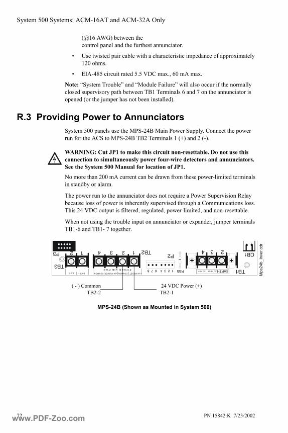
System 500 Systems: ACM-16AT and ACM-32A Only
72 PN 15842:K 7/23/2002
(@16 AWG) between the control panel and the furthest annunciator.
• Use twisted pair cable with a characteristic impedance of approximately 120 ohms.
• EIA-485 circuit rated 5.5 VDC max., 60 mA max.
Note: “System Trouble” and “Module Failure” will also occur if the normally closed supervisory path between TB1 Terminals 6 and 7 on the annunciator is opened (or the jumper has not been installed).
R.3 Providing Power to AnnunciatorsSystem 500 panels use the MPS-24B Main Power Supply. Connect the power run for the ACS to MPS-24B TB2 Terminals 1 (+) and 2 (-).
No more than 200 mA current can be drawn from these power-limited terminals in standby or alarm.
The power run to the annunciator does not require a Power Supervision Relay because loss of power is inherently supervised through a Communications loss. This 24 VDC output is filtered, regulated, power-limited, and non-resettable.
When not using the trouble input on annunciator or expander, jumper terminals TB1-6 and TB1- 7 together.
!WARNING: Cut JP1 to make this circuit non-resettable. Do not use this connection to simultaneously power four-wire detectors and annunciators. See the System 500 Manual for location of JP1.
P3
TB3
TB2
TB1
CB1P2
R551 2 3 4 6 7 8 EARTHAC NEUTCOMMONCOMMONBATT - +24 VRESET
AC HOT+24 VPOWERBATT +
2 3 41 2 3 41 2
Mps
24b_
Inve
r.cdr
( - ) CommonTB2-2
24 VDC Power (+) TB2-1
MPS-24B (Shown as Mounted in System 500)
www.PDF-Zoo.com
System 500 Systems: ACM-16AT and ACM-32A Only
PN 15842:K 7/23/2002 73
R.4 Configuring the ACS for System 500 Note: Address and DIP switches must be set before the annunciator will operate properly.
DIP Switch settings
Switch # ACM-16AT and ACM-32A Function1 Not used: This switch must be set “OFF”
2, 3 Expanders installed: Set these switches according to how many expanders are installed at the address. See Section 4.13.3 “Configuring Number of Expander Modules”
4 Eight-Point Shift: Set switch “ON” to switch the control panel functions out of the first eight annunciator points. This switch is intended for systems between 9 and 16 circuits and employing one ACM-16AT (with no expander) where annunciation of all circuits is desired.
5 Receive Only: Set this switch “ON” for each annunciator that will provide the same information as another annunciator in a different location. (When two or more annunciators hold the same address, all but one must be configured as “Receive Only” annunciators.)
6 Piezo Disable: Set this switch “ON” to disable the piezo from sounding for any event. (The piezo will also be disabled if Flash Inhibit is “ON”.)
7 Switch Inhibit: Set this switch “ON” to disable the point control switches on the annunciator and prevent them from executing system control functions. When inhibited, the switches will serve as local Lamp Test switches only. In addition, the Acknowledge/Lamp Test switch will function only in a local capacity unrecognized by the system. NOTE: Only the first four switches control the System 500. Their functions are: 1=Acknowledge 2=Signal Silence, 3=System Reset, 4=Drill.
8 Flash Inhibit: Set this switch “ON” to disable the flashing of LEDs associated with unacknowledged events. Flash Inhibit also disables the piezo from sounding.
www.PDF-Zoo.com
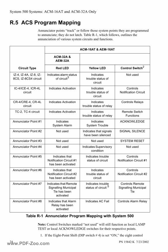
System 500 Systems: ACM-16AT and ACM-32A Only
74 PN 15842:K 7/23/2002
R.5 ACS Program MappingAnnunciator points “track” or follow those system points they are programmed to annunciate; they do not latch. Table R-1, which follows, outlines the annunciation of various system circuits and functions.
Note: Control Switches marked “not used” will still function as local LAMP TEST or local ACKNOWLEDGE switches for their respective points.
1. If the Eight-Point Shift (DIP switch # 4) is set “ON,” the eight control
Circuit Type
ACM-16AT & AEM-16AT
ACM-32A & AEM-32A
Red LED Yellow LED Control Switch2
IZ-4, IZ-4A, IZ-8, IZ-8CS, IZ-8CS4 circuit
Indicates alarm status of circuit3
Indicates trouble status of
circuit
Not used
IC-4/ICE-4, ICR-4L circuit
Indicates Activation Indicates trouble status of
circuit
Controls Notification Circuit
CR-4/CRE-4, CR-4L circuit
Indicates Activation Indicates trouble status of relay
Controls Relays
TC-2, TC-4 circuit Indicates Activation Indicates trouble status of relay
Remote Switch Functions
Annunciator Point #1 Indicates System Alarm
Indicates System Trouble
ACKNOWLEDGE
Annunciator Point #2 Not used Indicates that signals have been silenced
SIGNAL SILENCE
Annunciator Point #3 Not used Not used SYSTEM RESET
Annunciator Point #4 Not used Indicates Supervisory condition
Not used
Annunciator Point #5 Indicates that Notification Circuit #1 has been activated
Indicates trouble status of circuit
Controls Notification Circuit #1
Annunciator Point #6 Indicates that Notification Circuit #2 has been activated
Indicates trouble status of
circuit
Controls Notification Circuit #2
Annunciator Point #7 Indicates that Remote Signalling Municipal
Tie has been activated
Indicates trouble status of circuit 5
Controls Remote Signalling Municipal
Tie
Annunciator Point #8 Indicates that Alarm Relay has been
activated
Indicates AC Fail Controls Alarm Relay
Table R-1 Annunciator Program Mapping with System 500
www.PDF-Zoo.com
System 500 Systems: ACM-16AT and ACM-32A Only
PN 15842:K 7/23/2002 75
panel functions will be shifted out of annunciator points 1 through 8. Those eight points will annunciate the first module.
2. These control switches are active only if all of these conditions are set:
• Receive Only (DIP Switch # 5) is set to “OFF.”
• Switch Inhibit (DIP Switch # 7) is set to “OFF.”
3. With Software P/N #S500R4.0 or higher installed in the System 500, the manner in which IZ-8, IZ-8CS, and IZ-8CS4 circuits programmed as supervisory are annunciated depends upon whether Mode 1 or Mode 2 is selected.
4. ICR-4L and CR-4L circuits are annunciated as points 41-44 when installed behind the middle module or points 49-52 when installed behind the right-hand side module.
5. Annunciator Point #7 yellow LED indicates Municipal Tie Trouble if no UDACT is installed. It will annunciate Low Battery Ground Fault if a UDACT is installed in the system.
www.PDF-Zoo.com

System 5000 Systems: ACM-16AT and ACM-32A Only
76 PN 15842:K 7/23/2002
APPENDIX S System 5000 Systems: ACM-16AT and ACM-32A Only
S.1 CapabilitiesWhen installed with a System 5000, the ACS can annunciate the status of initiating and notification circuits, relays, and several system control functions. Each annunciator LED is automatically assigned to one and only one system point.
Circuits:• IZM-8 Initiating Device Circuits (alarm and trouble) • ICM-4/ICE-4 Notification Appliance Circuits (trouble)*• CRM-4/CRE-4 Control Relays (trouble)*• TCM-2 circuits (trouble)*• TCM-4 circuits (trouble)*• VCM-4/DCM-4 circuits (trouble)*• AIM-200 zones (alarm and trouble)
*Indication of output circuit activation can be obtained by programming the control panel for “OUTPUT STATUS.”
System Controls:• Acknowledge• Signal Silence• System Reset
Activate Notification Circuits 1 and 2, the Remote Signalling Municipal Tie circuit, and the Alarm Relay.
S.2 Connecting the EIA-485 CircuitCommunication between the control panel and the Annunciator Control System is accomplished over a two-wire EIA-485 serial interface. This communication circuit is supervised by the System. To operate the ACS, the control panel must be Revision D or greater. The revision level of the control panel is marked on a label affixed to the upper board. Additionally, the system must be operating under control panel software with U4 ROM part number 73085 or higher.
Loss of communication results in “System Trouble” and “Module Failure” indications at the control panel.
-
+
5000
tb1.
cdr
TB2 on main boardof System 5000
www.PDF-Zoo.com

System 5000 Systems: ACM-16AT and ACM-32A Only
PN 15842:K 7/23/2002 77
Note: “System Trouble” and “Module Failure” will also occur if the normally closed supervisory path between TB1 Terminals 6 and 7 on the annunciator is opened (or the jumper has not been installed).
The EIA-485 circuit that drives the ACS must be connected to the control panel as in the accompanying illustration.
• Power-limited and supervised.• 6,000 feet maximum distance (@16 AWG) between the control panel
and the furthest annunciator.• Use twisted pair cable with a characteristic impedance of approximately
120 ohms.• EIA-485 circuit rated 5.5 VDC max., 60 mA max.
S.3 Providing Power to Annunciators MPS-24A Main Power Supply. Connect the power run for the ACS to +24V non-resettable power on TB3 of MPS-24A, as shown in accompanying illustration (filtered, power-limited, 3 amps max).
MPS-24B Main Power Supply. Cut JP1 on MPS-24B to make the circuit non-resettable and connect the power run for the ACS to MPS-24B TB2 Terminals 1 (+) and 2 (-) as shown in the accompanying illustration (filtered, power-limited, 200 milliamps max).
TB2 TB3
+ -
TB3TB2
+ -
POWER LIMITED+24R COMMON +24 COMMON
POWER LIMITED+24RST COMMON +24 COMMON ac
s500
0pw
r.cdr
24 VDC
24 VDC
!WARNING: Cut JP1 on MPS-24B to make this circuit non-resettable. Do not use this connection to simultaneously power four-wire detectors and annunciators. See the System 5000 Manual for location of JP1.
www.PDF-Zoo.com
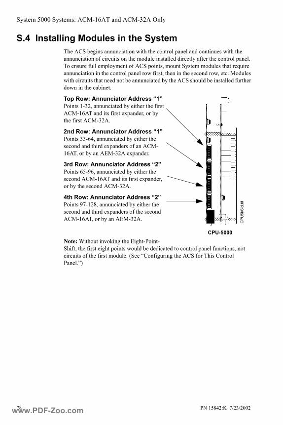
System 5000 Systems: ACM-16AT and ACM-32A Only
78 PN 15842:K 7/23/2002
S.4 Installing Modules in the SystemThe ACS begins annunciation with the control panel and continues with the annunciation of circuits on the module installed directly after the control panel. To ensure full employment of ACS points, mount System modules that require annunciation in the control panel row first, then in the second row, etc. Modules with circuits that need not be annunciated by the ACS should be installed further down in the cabinet.
Top Row: Annunciator Address “1”Points 1-32, annunciated by either the first ACM-16AT and its first expander, or by the first ACM-32A.
2nd Row: Annunciator Address “1”Points 33-64, annunciated by either the second and third expanders of an ACM-16AT, or by an AEM-32A expander.
3rd Row: Annunciator Address “2”Points 65-96, annunciated by either the second ACM-16AT and its first expander, or by the second ACM-32A.
4th Row: Annunciator Address “2”Points 97-128, annunciated by either the second and third expanders of the second ACM-16AT, or by an AEM-32A.
Note: Without invoking the Eight-Point-Shift, the first eight points would be dedicated to control panel functions, not circuits of the first module. (See “Configuring the ACS for This Control Panel.”)
CPU-5000C
PU5k
Sid.
tif
www.PDF-Zoo.com

System 5000 Systems: ACM-16AT and ACM-32A Only
PN 15842:K 7/23/2002 79
S.5 Configuring the ACS for System 5000Note: Address and DIP switches must be set before the annunciator will operate properly. The annunciator can be set for addresses 1, 2, 3 or 4. (Annunciator Address “3” and “4” are used with AIM-200. Refer to “AIM-200 Point Annunciation” on page 81.) The actual mapping arrangement for a respective annunciator module and its expanders depends on System annunciator programming. Refer to the System 5000 Programming Manual for a more detailed explanation.
DIP Switch settings
Switch # ACM-16AT and ACM-32A Function1 Not used: This switch must be set “OFF”
2, 3 Expanders installed: Set these switches according to how many expanders are installed at the address. See Section 4.13.3 “Configuring Number of Expander Modules”
4 Eight-Point Shift: Set switch “ON” to shift the control panel functions from the first eight annunciator positions to expander positions 57-64. This shift can only be set on an annunciator set for address “1”.
5 Receive Only: Set this switch “ON” for each annunciator that will provide the same information as another annunciator in a different location. (When two or more annunciators hold the same address, all but one must be configured as “Receive Only” annunciators.)
6 Piezo Disable: Set this switch “ON” to disable the piezo from sounding for any event. (The piezo will also be disabled if Flash Inhibit is “ON”.)
7 Switch Inhibit: Set this switch “ON” to disable the point control switches on the annunciator and prevent them from executing system control functions. When inhibited, the switches will serve as local Lamp Test switches only. In addition, the Acknowledge/Lamp Test switch will function only in a local capacity unrecognized by the system. NOTE: Only the first four switches control the System 5000. Their functions are: 1=Acknowledge 2=Signal Silence, 3=System Reset, 4=Drill.
8 Flash Inhibit: Set this switch “ON” to disable the flashing of LEDs associated with unacknowledged events. Flash Inhibit also disables the piezo from sounding.
www.PDF-Zoo.com

System 5000 Systems: ACM-16AT and ACM-32A Only
80 PN 15842:K 7/23/2002
S.6 ACS Program MappingAnnunciator points “track” or follow those system points they are programmed to annunciate; they do not latch. Table S-1 outlines the annunciation of various system circuits and functions.
Note: Control Switches marked “not used” will still function as local LAMP TEST or local ACKNOWLEDGE switches for their respective points.
1. If the Eight-Point Shift (DIP switch #4) is set “ON”, the eight control panel functions will be shifted from annunciator points 1 through 8 to points 57 through 64 (provided those points exist in the system).
Circuit Type
ACM-16AT & AEM-16AT
ACM-32A & AEM-32A
Red LED Yellow LED Control Switch2
IZM-8, IZM-8CS, IZM-8CS4 circuit
Indicates alarmstatus of circuit6
Indicates trouble status of circuit
Not used
ICM-4/ICE-4 circuit Indicates Activation3 Indicates trouble status of circuit
Controls Notification Circuit4
CRM-4/CRE-4 circuit Indicates Activation3 Indicates trouble status of relay
Controls Relays4
TCM-2, TCM-4VCM-4, DCM-4 circuit
Indicates Activation3 Indicates trouble status of relay
Remote Switch Functions4
AIM-200 zone5 Indicates alarm status of circuit
Indicates trouble status of circuit
Not used
Annunciator Point #11 Indicates System Alarm
Indicates System Trouble
ACKNOWLEDGE
Annunciator Point #2 Not used Indicates signals have been silenced
SIGNAL SILENCE
Annunciator Point #3 Not used Not used SYSTEM RESET
Annunciator Point #4 Not used Indicates Supervisory condition
Not used
Annunciator Point #5 Indicates that Notification Circuit 1 has been activated
Indicates trouble status of circuit
Controls Notification Circuit #1
Annunciator Point #6 Indicates that Notification Circuit 2 has been activated
Indicates trouble status of circuit
Controls Notification Circuit 2
Annunciator Point #7 Indicates that the Remote Signalling to
Municipal Tie has been activated
Indicates trouble status of circuit7
Controls Remote Signalling Municipal Tie
Annunciator Point #8 Indicates that the Alarm Relay has been
activated
Indicates AC Fail Controls Alarm Relay
Table S-1 Annunciator Program Mapping with System 5000
www.PDF-Zoo.com
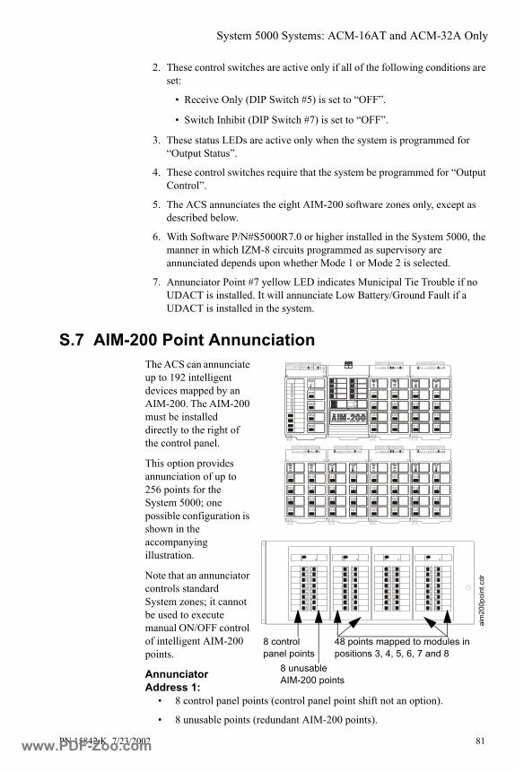
System 5000 Systems: ACM-16AT and ACM-32A Only
PN 15842:K 7/23/2002 81
2. These control switches are active only if all of the following conditions are set:
• Receive Only (DIP Switch #5) is set to “OFF”.
• Switch Inhibit (DIP Switch #7) is set to “OFF”.
3. These status LEDs are active only when the system is programmed for “Output Status”.
4. These control switches require that the system be programmed for “Output Control”.
5. The ACS annunciates the eight AIM-200 software zones only, except as described below.
6. With Software P/N#S5000R7.0 or higher installed in the System 5000, the manner in which IZM-8 circuits programmed as supervisory are annunciated depends upon whether Mode 1 or Mode 2 is selected.
7. Annunciator Point #7 yellow LED indicates Municipal Tie Trouble if no UDACT is installed. It will annunciate Low Battery/Ground Fault if a UDACT is installed in the system.
S.7 AIM-200 Point AnnunciationThe ACS can annunciate up to 192 intelligent devices mapped by an AIM-200. The AIM-200 must be installed directly to the right of the control panel.
This option provides annunciation of up to 256 points for the System 5000; one possible configuration is shown in the accompanying illustration.
Note that an annunciator controls standard System zones; it cannot be used to execute manual ON/OFF control of intelligent AIM-200 points.
Annunciator Address 1:
• 8 control panel points (control panel point shift not an option).
• 8 unusable points (redundant AIM-200 points).
J11J11
8 control panel points
48 points mapped to modules in positions 3, 4, 5, 6, 7 and 8
8 unusable AIM-200 points
aim
200p
oint
.cdr
www.PDF-Zoo.com

System 5000 Systems: ACM-16AT and ACM-32A Only
82 PN 15842:K 7/23/2002
• 48 points mapped to the next six modules installed in the System (which can also be AIM-200s for annunciation of their eight software zones).
Annunciator Address 2: • Intelligent Detectors, addressed 1-64, on the AIM-200 installed next to
the control panel.
Annunciator Address 3: • Addressable Modules, addressed 1-64, on the AIM-200 installed next to
the control panel.
Annunciator Address 4: • Intelligent Detectors, addressed 65-96, followed by Addressable
Modules, addressed 65-96, on the AIM-200 installed next to the control panel. The control panel’s programming manual provides programming instructions for this option. Refer to program choice “AIM(256)”.
Note: AIM-200 detector and module addresses 97, 98, and 99 may be used, but cannot be point-annunciated.
www.PDF-Zoo.com

Combination Fire Alarm/Burglary Systems
PN 15842:K 7/23/2002 83
APPENDIX T Combination Fire Alarm/Burglary SystemsACS annunciators can be used in combination fire/burglary and burglary systems within the requirements set forth in this appendix.
1. Shielded cable must be used on all input/output wiring. Terminate both ends of the shield at earth ground.
2. The annunciators shall be mounted within the protected area.
3. A pair of LEDs shall be set up to indicate the status of the zones covered in a given premise and for the arm/disarm status.
4. Further requirements governing installation and programming are covered in manuals for individual control panels (see Section 1.2 “Related Documentation” for part numbers).
www.PDF-Zoo.com
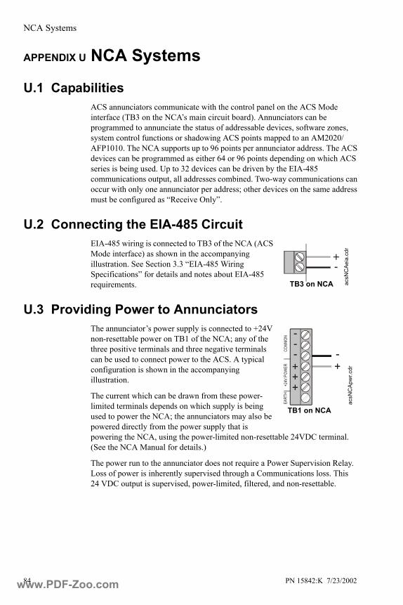
NCA Systems
84 PN 15842:K 7/23/2002
APPENDIX U NCA Systems
U.1 Capabilities ACS annunciators communicate with the control panel on the ACS Mode interface (TB3 on the NCA’s main circuit board). Annunciators can be programmed to annunciate the status of addressable devices, software zones, system control functions or shadowing ACS points mapped to an AM2020/AFP1010. The NCA supports up to 96 points per annunciator address. The ACS devices can be programmed as either 64 or 96 points depending on which ACS series is being used. Up to 32 devices can be driven by the EIA-485 communications output, all addresses combined. Two-way communications can occur with only one annunciator per address; other devices on the same address must be configured as “Receive Only”.
U.2 Connecting the EIA-485 CircuitEIA-485 wiring is connected to TB3 of the NCA (ACS Mode interface) as shown in the accompanying illustration. See Section 3.3 “EIA-485 Wiring Specifications” for details and notes about EIA-485 requirements.
U.3 Providing Power to AnnunciatorsThe annunciator’s power supply is connected to +24V non-resettable power on TB1 of the NCA; any of the three positive terminals and three negative terminals can be used to connect power to the ACS. A typical configuration is shown in the accompanying illustration.
The current which can be drawn from these power-limited terminals depends on which supply is being used to power the NCA; the annunciators may also be powered directly from the power supply that is powering the NCA, using the power-limited non-resettable 24VDC terminal. (See the NCA Manual for details.)
The power run to the annunciator does not require a Power Supervision Relay. Loss of power is inherently supervised through a Communications loss. This 24 VDC output is supervised, power-limited, filtered, and non-resettable.
+-
acsN
CAe
ia.c
dr
TB3 on NCA
acsN
CAp
wr.c
dr
TB1 on NCA
++++
----
+24V
POW
ERCO
MMON
EA
RTH
www.PDF-Zoo.com

NCA Systems
PN 15842:K 7/23/2002 85
U.4 Programming the NCA for Remote AnnunciationAnnunciator points must be programmed from the NCA before the annunciators will function. The NCA employ the following format for annunciator points:
Note: To program the annunciators into NCA memory, and to map system points and software zones to annunciator points, refer to the NCA Manual.
Note: When using the NCA to annunciate points on the AM2020/AFP1010 over the network, enable state reporting in the AM2020/AFP1010 panel for control module points and “NONA”/”NOA” module points; refer to the NCA Manual for instructions.
A(xx) P(yy)
Annunciator addressIn the range of 1-32, as set on the annunciator’s rotary decimal switches.
Annunciator Points per Module
*Note: Points 65-96 are not used unless ACS device is programmed for 96 points.
ACM-24AT, Points 1-24
First AEM-24AT, Points 25-48
Second AEM-24AT, Points 49-72*
Third AEM-24AT, Points 73-96*
ACM-48A, Points 1-48
AEM-48A, Points 49-96*
ACM-16AT, Points 1-16
First AEM-16AT, Points 17-32
Second AEM-16AT, Points 33-48
Third AEM-16AT, Points 49-64
ACM-32A, Points 1-32
AEM-32A, Points 33-64
www.PDF-Zoo.com
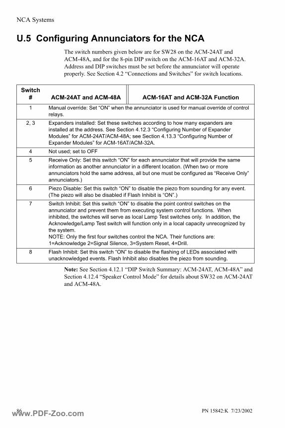
NCA Systems
86 PN 15842:K 7/23/2002
U.5 Configuring Annunciators for the NCAThe switch numbers given below are for SW28 on the ACM-24AT and ACM-48A, and for the 8-pin DIP switch on the ACM-16AT and ACM-32A. Address and DIP switches must be set before the annunciator will operate properly. See Section 4.2 “Connections and Switches” for switch locations.
Note: See Section 4.12.1 “DIP Switch Summary: ACM-24AT, ACM-48A” and Section 4.12.4 “Speaker Control Mode” for details about SW32 on ACM-24AT and ACM-48A.
Switch # ACM-24AT and ACM-48A ACM-16AT and ACM-32A Function1 Manual override: Set “ON” when the annunciator is used for manual override of control
relays.2, 3 Expanders installed: Set these switches according to how many expanders are
installed at the address. See Section 4.12.3 “Configuring Number of Expander Modules” for ACM-24AT/ACM-48A; see Section 4.13.3 “Configuring Number of Expander Modules” for ACM-16AT/ACM-32A.
4 Not used; set to OFF5 Receive Only: Set this switch “ON” for each annunciator that will provide the same
information as another annunciator in a different location. (When two or more annunciators hold the same address, all but one must be configured as “Receive Only” annunciators.)
6 Piezo Disable: Set this switch “ON” to disable the piezo from sounding for any event. (The piezo will also be disabled if Flash Inhibit is “ON”.)
7 Switch Inhibit: Set this switch “ON” to disable the point control switches on the annunciator and prevent them from executing system control functions. When inhibited, the switches will serve as local Lamp Test switches only. In addition, the Acknowledge/Lamp Test switch will function only in a local capacity unrecognized by the system. NOTE: Only the first four switches control the NCA. Their functions are: 1=Acknowledge 2=Signal Silence, 3=System Reset, 4=Drill.
8 Flash Inhibit: Set this switch “ON” to disable the flashing of LEDs associated with unacknowledged events. Flash Inhibit also disables the piezo from sounding.
www.PDF-Zoo.com

NFS-3030 Systems
PN 15842:K 7/23/2002 87
APPENDIX V NFS-3030 Systems
V.1 CapabilitiesWhen installed with an NFS-3030, annunciators can be programmed to annunciate the status of addressable devices, general zones, logic zones, and several system control functions:
Devices• Intelligent Detectors• Monitor and Control Modules• Addressable Manual Pull Stations• Wireless Devices• Panel Circuit Modules
Note: Refer to the appropriate FACP manuals for more information.
Zones 0-999
Logic Zones 1-1000
System Controls• Acknowledge• Signal Silence• System Reset• Lamp Test• Drill• Disable• Monitor• Control• Telephone
XP Series Transponder System• Power and Audio Supply Supervision• XP Series Form-C Alarm and Trouble Relays• Control, Monitor, and Relay Module Circuits
V.2 Connecting the EIA-485 Circuit One ACS circuit may be connected to the NFS-3030 as shown in the accompanying illustration. The NFS-3030 must be at the end of the EIA-485 circuit.
See Section 3.3 “EIA-485 Wiring Specifications” for details and notes about EIA-485 requirements.
+ -
3030
-AC
S-TB
7.cd
r
TB7 on NFS-3030
www.PDF-Zoo.com

NFS-3030 Systems
88 PN 15842:K 7/23/2002
V.3 Providing Power to Annunciators The annunciator’s power supply is connected to TB6 on the AMPS-24/E, as shown in the accompanying illustrations. The power run to the annunciator does not require a Power Supervision Relay. Loss of power is inherently supervised through a Communications loss. This 24 VDC output is supervised, filtered, and non-resettable. It is power-limited only if the +5V output on this terminal block is not used.
V.4 Programming the NFS-3030 for Remote Annunciation
Annunciator points must be programmed from the NFS-3030 before the annunciators will function. The NFS-3030 employs the following format for annunciator points:
Note: To program the annunciators into NFS-3030 memory, and to map system points and logic zones to annunciator points, refer to the NFS-3030 Manual.
TB6 on AMPS-24/E
amps
24-a
cspo
wer
.cdr
A(xx) P(yy)
Annunciator addressIn the range of 1-32, as set on the annunciator’s rotary decimal switches.
Annunciator Points per Module
* To use Points 65-96, program the ACS device for 96 points.
ACM-24AT, Points 1-24
First AEM-24AT, Points 25-48
Second AEM-24AT, Points 49-72*
Third AEM-24AT, Points 73-96*
ACM-48A, Points 1-48
AEM-48A, Points 49-96*
ACM-16AT, Points 1-16
First AEM-16AT, Points 17-32
Second AEM-16AT, Points 33-48
Third AEM-16AT, Points 49-64
ACM-32A, Points 1-32
AEM-32A,Points 33-64
www.PDF-Zoo.com
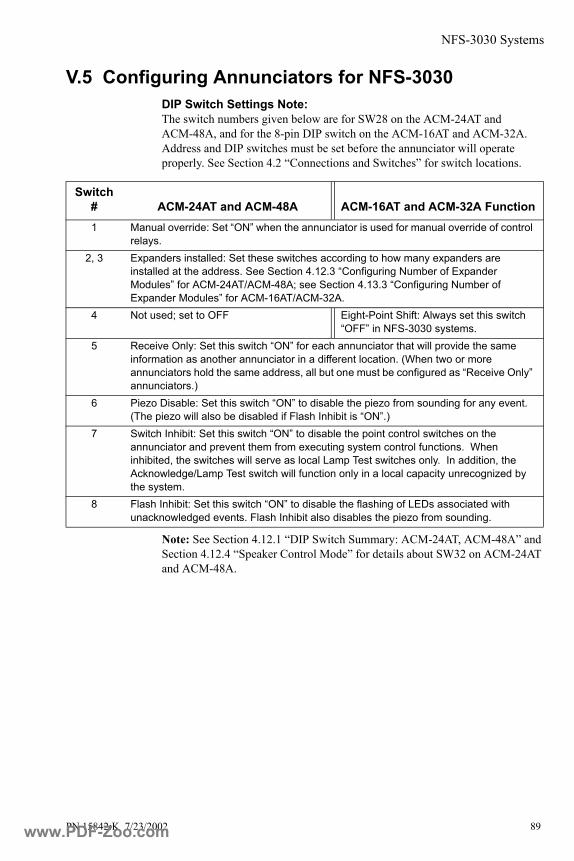
NFS-3030 Systems
PN 15842:K 7/23/2002 89
V.5 Configuring Annunciators for NFS-3030DIP Switch Settings Note:The switch numbers given below are for SW28 on the ACM-24AT and ACM-48A, and for the 8-pin DIP switch on the ACM-16AT and ACM-32A. Address and DIP switches must be set before the annunciator will operate properly. See Section 4.2 “Connections and Switches” for switch locations.
Note: See Section 4.12.1 “DIP Switch Summary: ACM-24AT, ACM-48A” and Section 4.12.4 “Speaker Control Mode” for details about SW32 on ACM-24AT and ACM-48A.
Switch # ACM-24AT and ACM-48A ACM-16AT and ACM-32A Function1 Manual override: Set “ON” when the annunciator is used for manual override of control
relays.2, 3 Expanders installed: Set these switches according to how many expanders are
installed at the address. See Section 4.12.3 “Configuring Number of Expander Modules” for ACM-24AT/ACM-48A; see Section 4.13.3 “Configuring Number of Expander Modules” for ACM-16AT/ACM-32A.
4 Not used; set to OFF Eight-Point Shift: Always set this switch “OFF” in NFS-3030 systems.
5 Receive Only: Set this switch “ON” for each annunciator that will provide the same information as another annunciator in a different location. (When two or more annunciators hold the same address, all but one must be configured as “Receive Only” annunciators.)
6 Piezo Disable: Set this switch “ON” to disable the piezo from sounding for any event. (The piezo will also be disabled if Flash Inhibit is “ON”.)
7 Switch Inhibit: Set this switch “ON” to disable the point control switches on the annunciator and prevent them from executing system control functions. When inhibited, the switches will serve as local Lamp Test switches only. In addition, the Acknowledge/Lamp Test switch will function only in a local capacity unrecognized by the system.
8 Flash Inhibit: Set this switch “ON” to disable the flashing of LEDs associated with unacknowledged events. Flash Inhibit also disables the piezo from sounding.
www.PDF-Zoo.com
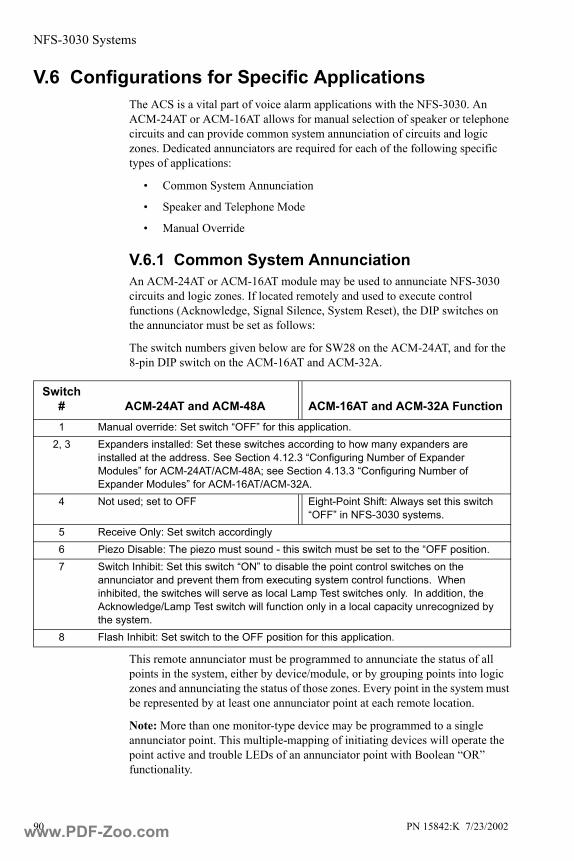
NFS-3030 Systems
90 PN 15842:K 7/23/2002
V.6 Configurations for Specific ApplicationsThe ACS is a vital part of voice alarm applications with the NFS-3030. An ACM-24AT or ACM-16AT allows for manual selection of speaker or telephone circuits and can provide common system annunciation of circuits and logic zones. Dedicated annunciators are required for each of the following specific types of applications:
• Common System Annunciation
• Speaker and Telephone Mode
• Manual Override
V.6.1 Common System AnnunciationAn ACM-24AT or ACM-16AT module may be used to annunciate NFS-3030 circuits and logic zones. If located remotely and used to execute control functions (Acknowledge, Signal Silence, System Reset), the DIP switches on the annunciator must be set as follows:
The switch numbers given below are for SW28 on the ACM-24AT, and for the 8-pin DIP switch on the ACM-16AT and ACM-32A.
This remote annunciator must be programmed to annunciate the status of all points in the system, either by device/module, or by grouping points into logic zones and annunciating the status of those zones. Every point in the system must be represented by at least one annunciator point at each remote location.
Note: More than one monitor-type device may be programmed to a single annunciator point. This multiple-mapping of initiating devices will operate the point active and trouble LEDs of an annunciator point with Boolean “OR” functionality.
Switch # ACM-24AT and ACM-48A ACM-16AT and ACM-32A Function1 Manual override: Set switch “OFF” for this application.
2, 3 Expanders installed: Set these switches according to how many expanders are installed at the address. See Section 4.12.3 “Configuring Number of Expander Modules” for ACM-24AT/ACM-48A; see Section 4.13.3 “Configuring Number of Expander Modules” for ACM-16AT/ACM-32A.
4 Not used; set to OFF Eight-Point Shift: Always set this switch “OFF” in NFS-3030 systems.
5 Receive Only: Set switch accordingly6 Piezo Disable: The piezo must sound - this switch must be set to the “OFF position.7 Switch Inhibit: Set this switch “ON” to disable the point control switches on the
annunciator and prevent them from executing system control functions. When inhibited, the switches will serve as local Lamp Test switches only. In addition, the Acknowledge/Lamp Test switch will function only in a local capacity unrecognized by the system.
8 Flash Inhibit: Set switch to the OFF position for this application.
www.PDF-Zoo.com
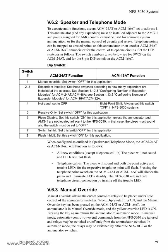
NFS-3030 Systems
PN 15842:K 7/23/2002 91
V.6.2 Speaker and Telephone Mode To execute audio functions, use an ACM-24AT or ACM-16AT set to address 1. This annunciator (and any expanders) must be installed adjacent to the AMG-1 and points assigned for AMG control cannot be used for common system annunciation, or for the manual control of circuits and relays. Telephone points can be mapped to unused points on this annunciator or on another ACM-24AT or ACM-16AT annunciator for the control of telephone circuits. Set the DIP switches as follows.The switch numbers given below are for SW28 on the ACM-24AT, and for the 8-pin DIP switch on the ACM-16AT.
Dip Switch:
When configured as outlined in Speaker and Telephone Mode, the ACM-24AT or ACM-16AT will function as follows:
• All new conditions (except telephone call-in) The piezo will not sound and LEDs will not flash.
• Telephone call-in: The piezo will sound and both the point active and trouble LEDs for the respective telephone point will flash. Pressing the telephone point switch on the ACM-24AT or ACM-16AT will silence the piezo and illuminate LEDs steadily. The NFS-3030 will indicate telephone circuit connection by turning off the trouble LED.
V.6.3 Manual OverrideManual Override allows the on/off control of relays to be placed under sole control of the annunciator switches. When Dip Switch 1 is ON, and the Manual Override key has been pressed on the ACM-24AT or ACM-16AT, the annunciator is in Manual Override mode, and the yellow override LED is ON. Pressing the key again returns the annunciator to automatic mode. In manual mode, automatic (control-by-event) commands from the NFS-3030 are ignored, and relays may be switched on/off only from the annunciator switches. In automatic mode, the relays may be switched by either the NFS-3030 or the annunciator switches.
Switch # ACM-24AT Function ACM-16AT Function1 Manual override: Set switch “OFF” for this application
2, 3 Expanders installed: Set these switches according to how many expanders are installed at the address. See Section 4.12.3 “Configuring Number of Expander Modules” for ACM-24AT/ACM-48A; see Section 4.13.3 “Configuring Number of Expander Modules” for ACM-16AT/ACM-32A.
4 Not used; set to OFF Eight-Point Shift: Always set this switch “OFF” in NFS-3030 systems.
5 Receive Only: Set switch “OFF” for this application.6 Piezo Disable: Set this switch “ON” for this application unless the annunciator and
AMG-1 are not located adjacent to the NFS-3030. In that case, the piezo must sound and the switch must be set to “OFF”.
7 Switch Inhibit: Set this switch”OFF” for this application.8 Flash Inhibit: Set this switch “ON” for this application.
www.PDF-Zoo.com

NFS-3030 Systems
92 PN 15842:K 7/23/2002
When in manual override mode, all points displayed on the ACM-24AT or ACM-16AT and all its expanders will ignore subsequent Control-by-Event (CBE) commands from the panel.
Manual Override Mode can be entered by pressing the Manual Override switch on the ACM-24AT or ACM-16AT module (Use special slide-in label).
• The Manual LED on the ACM-24AT or ACM-16AT module will illuminate steadily.
• The NFS-3030 will register an ANNUNCIATOR TROUBLE condition.
• The state of the each annunciator point will remain the same as before.
• The output circuits can now be controlled via their point switches.
The NFS-3030 Control-By-Event will not override the manual control setting of the ACM-24AT or ACM-16AT module. To return the annunciator to Automatic Mode, press the Manual Override switch again (toggle action). Set the DIP switches on a Manual Override annunciator as follows.The switch numbers given below are for SW28 on the ACM-24AT, and for the 8-pin DIP switch on the ACM-16AT.
Dip Switch:
!
Switch # ACM-24AT Function ACM-16AT Function1 Manual override: Set “ON” for this application.
2, 3 Expanders installed: Set these switches according to how many expanders are installed at the address. See Section 4.12.3 “Configuring Number of Expander Modules” for ACM-24AT/ACM-48A; see Section 4.13.3 “Configuring Number of Expander Modules” for ACM-16AT/ACM-32A.
4 Not used; set to OFF Eight-Point Shift: Always set this switch “OFF” in NFS-3030 systems.
5 Receive Only: Set this switch “OFF” for this application.6 Piezo Disable: Set this switch accordingly.7 Switch Inhibit: Set this switch “OFF” for this application.8 Flash Inhibit: Set this switch “OFF” for this application.
www.PDF-Zoo.com
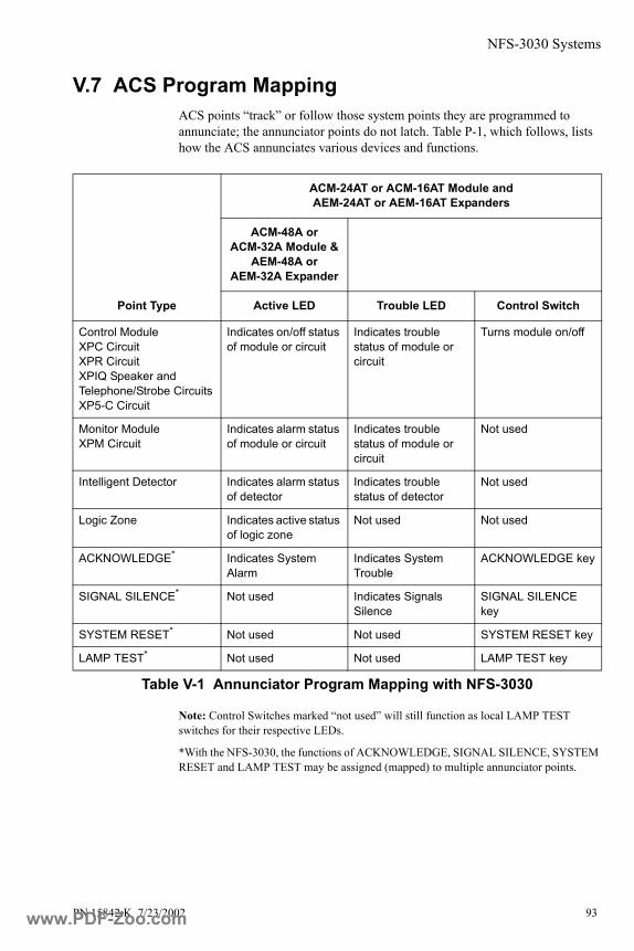
NFS-3030 Systems
PN 15842:K 7/23/2002 93
V.7 ACS Program Mapping ACS points “track” or follow those system points they are programmed to annunciate; the annunciator points do not latch. Table P-1, which follows, lists how the ACS annunciates various devices and functions.
Note: Control Switches marked “not used” will still function as local LAMP TEST switches for their respective LEDs.
*With the NFS-3030, the functions of ACKNOWLEDGE, SIGNAL SILENCE, SYSTEM RESET and LAMP TEST may be assigned (mapped) to multiple annunciator points.
Point Type
ACM-24AT or ACM-16AT Module and AEM-24AT or AEM-16AT Expanders
ACM-48A or ACM-32A Module &
AEM-48A or AEM-32A Expander
Active LED Trouble LED Control Switch
Control Module XPC CircuitXPR CircuitXPIQ Speaker and Telephone/Strobe CircuitsXP5-C Circuit
Indicates on/off status of module or circuit
Indicates trouble status of module or circuit
Turns module on/off
Monitor Module XPM Circuit
Indicates alarm status of module or circuit
Indicates trouble status of module or circuit
Not used
Intelligent Detector Indicates alarm status of detector
Indicates trouble status of detector
Not used
Logic Zone Indicates active status of logic zone
Not used Not used
ACKNOWLEDGE* Indicates System Alarm
Indicates System Trouble
ACKNOWLEDGE key
SIGNAL SILENCE* Not used Indicates Signals Silence
SIGNAL SILENCE key
SYSTEM RESET* Not used Not used SYSTEM RESET key
LAMP TEST* Not used Not used LAMP TEST key
Table V-1 Annunciator Program Mapping with NFS-3030
www.PDF-Zoo.com

NFS-3030 Systems
94 PN 15842:K 7/23/2002
Notes
www.PDF-Zoo.com

PN 15842:K 7/23/2002 95
AABF, ABS see BackboxesABM-1 18ACM-16AT 10, 26, 27, 41
Addressing 40Color variations 13DIP switches 40, 41Expanders 28, 29Keypad switches 45LEDs 45Supervising devices 41
ACM-24AT 9, 12, 26Addressing 36, 37DIP switches 36, 38, 42Expanders 28, 29Keypad switchesLEDs 42Speaker Control Mode 38
ACM-32A 10, 14, 26, 27, 41Addressing 40DIP switches 40, 41Expanders 28, 29Keypad switches 47, 48LEDs 47Supervising devices 41
ACM-48A 9, 12, 26Addressing 36, 37DIP switches 36, 42Expanders 28, 29Keypad switchesLEDs 42
AddressingACM-16AT, ACM-32A 40ACM-24AT 37ACM-48A 37Switch locations 26System 5000 78
Adhesive label 34ADP-4, ADP-4B 18AEM-16AT 10, 13
Keypad switches 46LEDs 46
AEM-24AT 9, 12DIP switches 42LEDs 42
AEM-32A 10, 14LEDs 48
AEM-48A 9, 12DIP switches 42LEDs 42
AFC-600 9DIP switches 57
Point annunciation 57Power connections 56Selection groups 57Speaker Control Mode 38
AFP-100 9DIP switches 50Power connections 49
AFP1010, see AM2020/AFP1010AFP-200 9
DIP switches 52, 54Power connections 51UDACT 40
AFP-300/AFP-400 9DIP switches 54Power connections 53Speaker Control Mode 38
AFP-400 see AFP-300/AFP-400AIM-200 81AKS-1(B), see Key switchAM2020 software requirements 60AM2020/AFP1010 9, 20
Applications 63Cabinet mounting 22Common system annunciation 63DIP switches 62, 63, 64, 65, 91Manual override 64, 91Power connections 60Speaker and Telephone Mode 64Speaker Control Mode 38
Annunciator key switch, see Key switch
Annunciator phone jack see Phone jack
Audio functions with AM2020/AFP1010 64
Audio functions with NFS-3030 91
BBackboxes 15, 16, 22, 28Battery calculations 23, 24BMP-1 18Burglary systems 83
CCabinet mounting 22, 28Cabinets see Backboxes, or DoorsCanada, National Standard of 8Common system annunciation
AM2020/AFP1010 63NFS-3030 90
Compatible panels 9Configuring the ACS
Index
www.PDF-Zoo.com

96 PN 15842:K 7/23/2002
AFC-600 57AFP-100 50AFP-200 52, 54AFP-300/AFP-400 54AM2020/AFP1010 62, 63DIP switch locations 26NCA 86NFS-3030 89, 90NFS-640 69System 500 73System 5000 79
Connecting Expanders 28, 29Control switch 80
Functions 44, 45, 46System 5000 80
Control switchesSystem 500 74
Current draw calculations 24Custom display labels 34
DDIP switches
ACM-16AT, ACM-32A 27, 40ACM-24AT 38, 42ACM-48A, AEM-48A 42AEM-24AT 42AFC-600 57AFP-100 50AFP-200 52, 54AFP-300/AFP-400 54AM2020/AFP1010 62, 64, 65, 91Configuring number of expander
modules 37, 41NCA 86NFS-3030 89, 91, 92NFS-640 69System 500 73System 5000 79with AM2020/AFP1010 63with NFS-3030 90
DP-DISP 18Dress plates 18, 29, 34
EEarth ground 32EIA-485 20, 30, 31
AFC-600 56AFP-100 49AFP-200 51AFP-300/AFP-400 53AM2020/AFP1010 59NFS-3030 87NFS-640 67, 84Shielding the circuit 31System 500 (ACM-16AT, ACM-
32A only) 71System 5000 (ACM-16AT, ACM-
32A only) 76Eight-point shift 40
System 500 73, 74System 5000 78, 79, 80
Electrical ratings 23End of line resistor 31, 35Expanders 28, 29
FFire/burglary systems 83
GGround 32
IInstallation Checklist 25Installation procedures 25Installing Modules in System
5000 78Installing modules in System
5000 78
KKey switch 34, 35Key switch connector 27keylock connector 35Keypad switches
AM2020/AFP1010 66NFS-3030 93
LLabeling 34Lamp test switch 46, 48LEDs 42
AM2020/AFP1010 66Color-programmable 42Inactive 46, 48NFS-3030 93Point-active 44, 45, 46, 47, 48System 500 74System 5000 80System Trouble 43, 44, 45, 47Trouble 44, 45, 46
Local silence/acknowledge switch 45, 47see also Acknowledge/Lamp Test
switch
MManual override 43, 45, 63, 64, 90,
91Mounting 28multiple power supplies 22, 23
www.PDF-Zoo.com
PN 15842:K 7/23/2002 97
multi-speakers 38
NNCA 38, 84
DIP switches 86NFS-3030 9, 10, 38, 87
Applications 90Common system annunciation 90DIP switches 89, 90, 92Power connections 88Speaker and Telephone Mode 91
NFS-640 9, 67DIP switches 69Selection groups 70Speaker Control Mode 38
OOn-line LED 43, 45, 47Overview
ACM-16AT 10ACM-24AT, AEM-24AT 9, 12ACM-32A 10, 14ACM-48A, AEM-48A 9, 12AEM-16AT 10, 13AEM-32A 10, 14Backboxes 15, 16Color variations 13Dress panels 18installation procedures 25Key switchPhone jack
PPhone jack 34, 35Point annunciation 57
AIM-200 81AM2020/AFP1010 61NCA 85NFS-3030 88NFS-640 70System 5000 81
Point mapping 39AFP-300/AFP-400 55
Point-active LEDs see LEDsPower connections 32, 33
AFC-600 56AFP-100 49AFP-200 51AFP-300/AFP-400 53AM2020/AFP1010 60NFS-3030 88NFS-640 68, 84System 500 72System 5000 77
Power Requirements 23
Program mappingAM2020/AFP1010 66NFS-3030 93System 500 74System 5000 80
RReceive Only Annunciators 21, 22Receive/transmit annunciators 21Related Documentation 11Remote annunciation, AM2020/
AFP1010 61Remote annunciation, NCA 85Remote annunciation, NFS-3030 88
SSelection groups
AFC-600 57AFP-300/AFP-400 55NFS-640 70
Semi-flush-mount Backboxes 16SIB, AM2020/AFP1010 59Slide-in labels 34Slide-in labels, see also center pagesSoftware requirements, AM2020 60Speaker and telephone mode
AM2020/AFP1010 63NFS-3030 90
Speaker Control Mode 38Specifications 20
Communication 20Electrical Ratings 23Power 23
Supervising devices with ACM-16AT, ACM-32A 41
Surface-Mount Backboxes 15Switch locations 26System 500
ACS program mapping 74Control switches 74DIP switches 73LEDs 74Power connections 72
System 5000 80ACS program mapping 80Control switches 80DIP switches 79EIA-485 76LEDs 80Power connections 77
System annunciation 57System Trouble LEDs see LEDs
TTesting 42
www.PDF-Zoo.com
98 PN 15842:K 7/23/2002
Trouble LEDs see LEDs
UUDACT
ACM-16AT, ACM-32A 40ACM-24AT, ACM-48A 37AFC-600 56AFP-200 40AFP-300/AFP-400 53NFS-640 67System 500 75System 5000 81
VVeriFire™ 9, 10, 56Voice applications, AM2020/
AFP1010 63Voice applications, NFS-3030 90VP-2, VP-2B 18
WWiring 28, 30, 33, 35
XXPIQ 38
ZZone mapping, AFP-300/AFP-
400 55
www.PDF-Zoo.com

Limited Warranty
NOTIFIER® warrants its products to be free from defects in materialsand workmanship for eighteen (18) months from the date ofmanufacture, under normal use and service. Products are datestamped at time of manufacture. The sole and exclusive obligation ofNOTIFIER® is to repair or replace, at its option, free of charge for partsand labor, any part which is defective in materials or workmanshipunder normal use and service. For products not under NOTIFIER®manufacturing date-stamp control, the warranty is eighteen (18)months from date of original purchase by NOTIFIER®’s distributorunless the installation instructions or catalog sets forth a shorter period,in which case the shorter period shall apply. This warranty is void if theproduct is altered, repaired or serviced by anyone other thanNOTIFIER® or its authorized distributors or if there is a failure tomaintain the products and systems in which they operate in a properand workable manner. In case of defect, secure a Return MaterialAuthorization form from our customer service department. Returnproduct, transportation prepaid, to NOTIFIER®, 12 Clintonville Road,Northford, Connecticut 06472-1653.
This writing constitutes the only warranty made by NOTIFIER® withrespect to its products. NOTIFIER® does not represent that itsproducts will prevent any loss by fire or otherwise, or that its productswill in all cases provide the protection for which they are installed orintended. Buyer acknowledges that NOTIFIER® is not an insurer andassumes no risk for loss or damages or the cost of any inconvenience,transportation, damage, misuse, abuse, accident or similar incident.
NOTIFIER® GIVES NO WARRANTY, EXPRESSED OR IMPLIED, OFMERCHANTABILITY, FITNESS FOR ANY PARTICULAR PURPOSE,OR OTHERWISE WHICH EXTEND BEYOND THE DESCRIPTIONON THE FACE HEREOF. UNDER NO CIRCUMSTANCES SHALLNOTIFIER® BE LIABLE FOR ANY LOSS OF OR DAMAGE TOPROPERTY, DIRECT, INCIDENTAL OR CONSEQUENTIAL,ARISING OUT OF THE USE OF, OR INABILITY TO USE NOTIFIER®PRODUCTS. FURTHERMORE, NOTIFIER® SHALL NOT BE LIABLEFOR ANY PERSONAL INJURY OR DEATH WHICH MAY ARISE INTHE COURSE OF, OR AS A RESULT OF, PERSONAL,COMMERCIAL OR INDUSTRIAL USE OF ITS PRODUCTS.
This warranty replaces all previous warranties and is the only warrantymade by NOTIFIER®. No increase or alteration, written or verbal, ofthe obligation of this warranty is authorized.
“NOTIFIER” is a registered trademark.
Warn-NS-10-2001.fm
www.PDF-Zoo.com

World Headquarters12 Clintonville Road
Northford, CT 06472-1653 USA203-484-7161
fax 203-484-7118
www.notifier.com
NOTIFIER is an operation of
www.PDF-Zoo.com


![D N K T K 1 EKSPERTYZA TECHNICZNA‚tusk.pdf · 2016-03-21 · 6.2.1Obci ążenie taborem samochodowym wg PN-85/S-10030 [7]. ... PN-EN 1991-2 Obciążenia ruchome mostów. [13] PN-EN](https://img.pdfslide.net/doc/110x75/5c75d1f109d3f2ff328bc526/d-n-k-t-k-1-ekspertyza-techniczna-tuskpdf-2016-03-21-621obci-azenie.jpg)