Embed Size (px)
Citation preview

Installation Manual IOM-MAB-00 08-15-04
MAB Modular Air Handler Belt Drive Installation, Operation, and Maintenance Manual
Contents PageIntroduction.............................................................1General ....................................................................1Safety .......................................................................1Inspection................................................................1Product Description ...............................................1Model Number Specification .............................................1Dimension Specification ....................................................2Blower and Plenum Information ........................................2
Standard Installation ..............................................4Ductwork ...........................................................................4Duct Insulation and Vapor Proofing...................................5Sound Attenuation.............................................................5Condensate Drain .............................................................5Water Piping......................................................................5Motors and Drives .............................................................6Electrical Connections.......................................................6
Installation of Options............................................6Grille Plenum.....................................................................6Mixing Box.........................................................................7Electric Heat......................................................................8
Air Handler Startup.................................................8Operation and Maintenance ..................................9Return Air Filters ...............................................................9Coil ....................................................................................9Belt and Pulley ..................................................................9Motor .................................................................................9Blower ...............................................................................9
Abbreviations..........................................................9
IntroductionThis document provides installation, operation, and maintenance information for the Titus Modular Air Handler Belt Drive (MAB) models.
Additional information may be found at the Titus website, www.titus-hvac.com.
GeneralThe following information is to be used by the installer as a guide. Since each installation is unique unto itself, only general topics are covered. Topic order may not be the same as required by actual installation.
This guide is not intended to supersede or circumvent any applicable national, state, or local codes.
The installation is to be performed only by individuals whose experience meets or exceeds the requirements of the work involved.
The installer MUST read the entire contents of this guide and develop a thorough understanding before beginning installation.
Due to a continuing program of product research, Titus reserves the right to discontinue or change without notice, any or all specifications or designs without incurring obligations.
Safety The installation and/or servicing of comfort conditioning equipment can be hazardous due to system pressures and electrical devices.
Caution: Only trained and qualified personnel should perform service and/or installation.
Observe all precautions and warnings in product data or attached to the unit.
Follow all safety codes. Wear eye protection and gloves. Have a fire extinguisher readily available.
Caution: Disconnect all power supplies before accessing equipment.
Disconnecting more than one power supply may be required to de-energize some equipment.
DANGER
ELECTRIC SHOCK CAN CAUSE DEATH.
Inspection Thoroughly inspect all packages upon receipt. Ensure carton(s) have not been dropped, crushed or punctured. Inspect all contents for damage. If damage is found, immediately file a claim with the delivering carrier.
Product Description This section provides model features, number nomenclature, various unit dimensions, and coil specification.
Model Number Specification The following figure defines model number nomenclature specifics.
605 Shiloh Road • Plano, Texas 75074 • 972-212-4800All rights reserved. No part of this work may be reproduced or transmitted in any form or any means, electronic or mechanical, including photocopying and recording, or by any information storage retrieval system without permission in writing from Air Distribution Technologies.

MAB Installation Manual IOM-MAB-00 08-15-04
2 of 9
Figure 1. Air Handler Model Number Nomenclature
Dimension Specification Figures 2 and 3 show dimensional callouts for all sides of an MAB unit. Tables 1 and 3 provide MAB model dimensional specifics such as tonnage, blower, filter dimensions, optional discharge or return air plenum, and shipping weight of plenum.
Blower and Plenum Information Tables 2 and 4 provide the blower coil and/or plenum specifics for MAB models. Table 5 provides water connection sizes based on model.
Figure 2. MAB08 & MAB12 Dimensional Views
Table 1. Cabinet Dimensions (MAB08 & MAB12)
Dimensions (inches) Model
A B C D E F G H J 1-inch Filter
MAB08/12 37 31.75 36 27.50 16 12 8.50 1.13 14.25 16 x 32
Table 2. Blower Coil Specifics (MAB08 & MAB12)
Rows/Fins Per Inch Coil Connection (OD Sweat) Model Nominal
CFMNominalCapacity (Tons)
HotWater
ChilledWater
Two-Row
Ship.Wgt.
Four-Row
Ship.Wgt.
Six-Row
Ship.Wgt.
MAB08 800 2 2/10 4/10 6/10 0.625 13 0.75 145 0.75 156 MAB12 1200 3 2/10 4/10 6/10 0.625 18 0.75 171 0.875 190

MAB Installation Manual IOM-MAB-00 08-15-04
3 of 9
Figure 3. Dimensional View
Table 3. Cabinet Dimensions
Model A B C D E F G H J K MAB16/20 40 26 27.5 36 25.5 11.88 13.63 1.13 13.13 21.25 MAB30/40 50 34 34.5 48 32 16.38 19 1.13 15.44 27 MAB60/80 72 34 47.5 66 45 16.38 16.38 1.13 14 34
Note: All dimensions in inches.

MAB Installation Manual IOM-MAB-00 08-15-04
4 of 9
Table 4. Blower Coil and Plenum Dimensions (MAB16 through MAB80)
Optional Discharge Grille Plenum Model Nominal
CFMNominalCapacity (Tons)
Blower 2” Filter Weight (lbs) Height
(inches) Grille Size (inches)
MAB16 1600 4 10 x 10 (2) 20 x 25 75 23 16 x 24 MAB20 2000 5 10 x 10 (2) 20 x 25 75 23 16 x 24 MAB30 3000 7.5 15 x 15 (4) 16 x 25 90 26-1/2 18 x 48 MAB40 4000 10 15 x 15 (4) 16 x 25 90 26-1/2 18 x 48 MAB60 6000 15
MAB80 8000 20 (2) 15 x 12
(2) 16 x 20 (2) 16 x 25 (2) 20 x 20 (2) 20 x 25
240 36 (4) 12 x 30
Table 5. MAB Water Coil Connection Size (OD SWT)
4-Row 6-Row 2-Row
Model Coil Size
ShipWeight
(lbs)Coil Size
ShipWeight
(lbs)Coil Size
ShipWeight
(lbs)MAB16 7/8" 321 1-1/8" 377 7/8" 30
MAB20 1-1/8" 344 1-1/8" 400 1-1/8" 34
MAB30 1-1/8" 584 1-3/8" 637 1-1/8" 49
MAB40 1-3/8" 584 1-5/8" 637 1-1/8" 53
MAB60 1-3/8" 844 1-5/8" 930 1-1/8" 86
MAB80 (2) 1-5/8" 890 (2) 1-5/8" 996 (2) 1-1/8" 106
Standard Installation Basic installation procedure covers verifying and/or installing the following items.
• Ductwork • Duct insulation and vapor proofing • Unit placement • Sound attenuation • Condensate drain • Water piping • Motors and drives • Electrical connections
Note: If mixing boxes form part of the unit, install the mixing boxes prior to installing unit. See Mixing Box installation instructions within this document.
DuctworkUse accepted industry practices and design guidelines of the ASHRAE Fundamentals Handbook. Ductwork must comply with all building codes and the National Fire Protection Association’s pamphlet 90A and 90B
Carefully inspect any previously installed ductwork to determine suitability.
Note: Ductwork should be of a size meeting requirements of the installation. Ductwork should transition gradually from a smaller size blower outlet to required duct run size to avoid excessive loss of air velocity.
MAB Installation Manual IOM-MAB-00 08-15-04
5 of 9
DANGER
BEFORE INSTALLING UNIT, DETERMINE IF THE UNIT WEIGHT CAN BE SAFELY SUPPORTED.
POSSIBLE INJURY AND DAMAGE MAY RESULT DUE TO JOIST/TRUSS OVERLOADING.
1. When return air duct connection is smaller than return air inlet opening, construct the transition piece so the horizontal and vertical dimensions of transition does not increase more than one inch for every seven feet of length.
2. Allow a minimum of three feet of straight ductwork following an equipment outlet.
3. Install unit with 1/8-inch pitch toward condensate drain opening.
Duct Insulation and Vapor Proofing Previously installed heating supply ductwork may already have adequate insulation against excessive heat loss. This insulation may be satisfactory for protection against heat gain from summer cooling. Depending upon application, additional insulation may be required.
Externally insulated ductwork must have adequate vapor seal for summer operation, especially where duct is exposed to high humidity conditions.
Sound Attenuation Flexible duct connections should be used between the unit and both the supply and return ducts.
Both suspended and base-mounted units require unit vibration isolation.
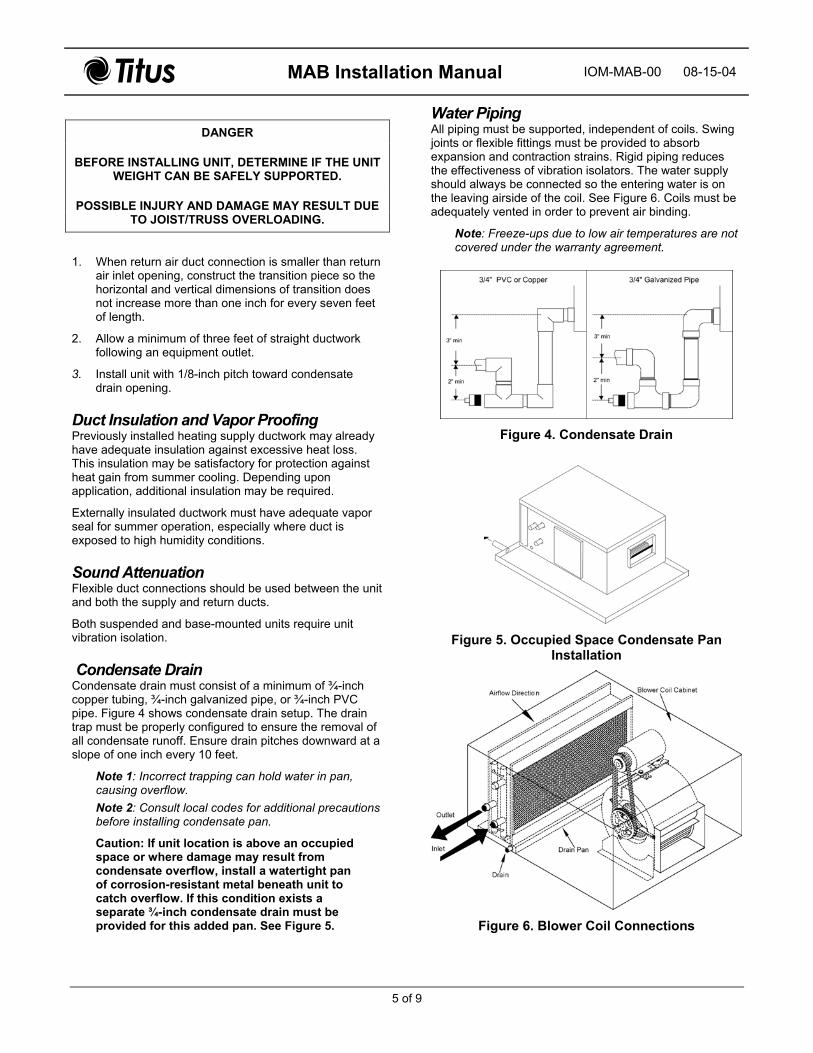
Condensate Drain Condensate drain must consist of a minimum of ¾-inch copper tubing, ¾-inch galvanized pipe, or ¾-inch PVC pipe. Figure 4 shows condensate drain setup. The drain trap must be properly configured to ensure the removal of all condensate runoff. Ensure drain pitches downward at a slope of one inch every 10 feet.
Note 1: Incorrect trapping can hold water in pan, causing overflow. Note 2: Consult local codes for additional precautions before installing condensate pan.
Caution: If unit location is above an occupied space or where damage may result from condensate overflow, install a watertight pan of corrosion-resistant metal beneath unit to catch overflow. If this condition exists a separate ¾-inch condensate drain must be provided for this added pan. See Figure 5.
Water Piping All piping must be supported, independent of coils. Swing joints or flexible fittings must be provided to absorb expansion and contraction strains. Rigid piping reduces the effectiveness of vibration isolators. The water supply should always be connected so the entering water is on the leaving airside of the coil. See Figure 6. Coils must be adequately vented in order to prevent air binding.
Note: Freeze-ups due to low air temperatures are not covered under the warranty agreement.
Figure 4. Condensate Drain
Figure 5. Occupied Space Condensate Pan Installation
Figure 6. Blower Coil Connections
MAB Installation Manual IOM-MAB-00 08-15-04
6 of 9
Motors and Drives Units are normally shipped with motor and drive installed. However; when mounting a motor on the adjustable base in the field, use extreme care to ensure proper alignment and belt tension.
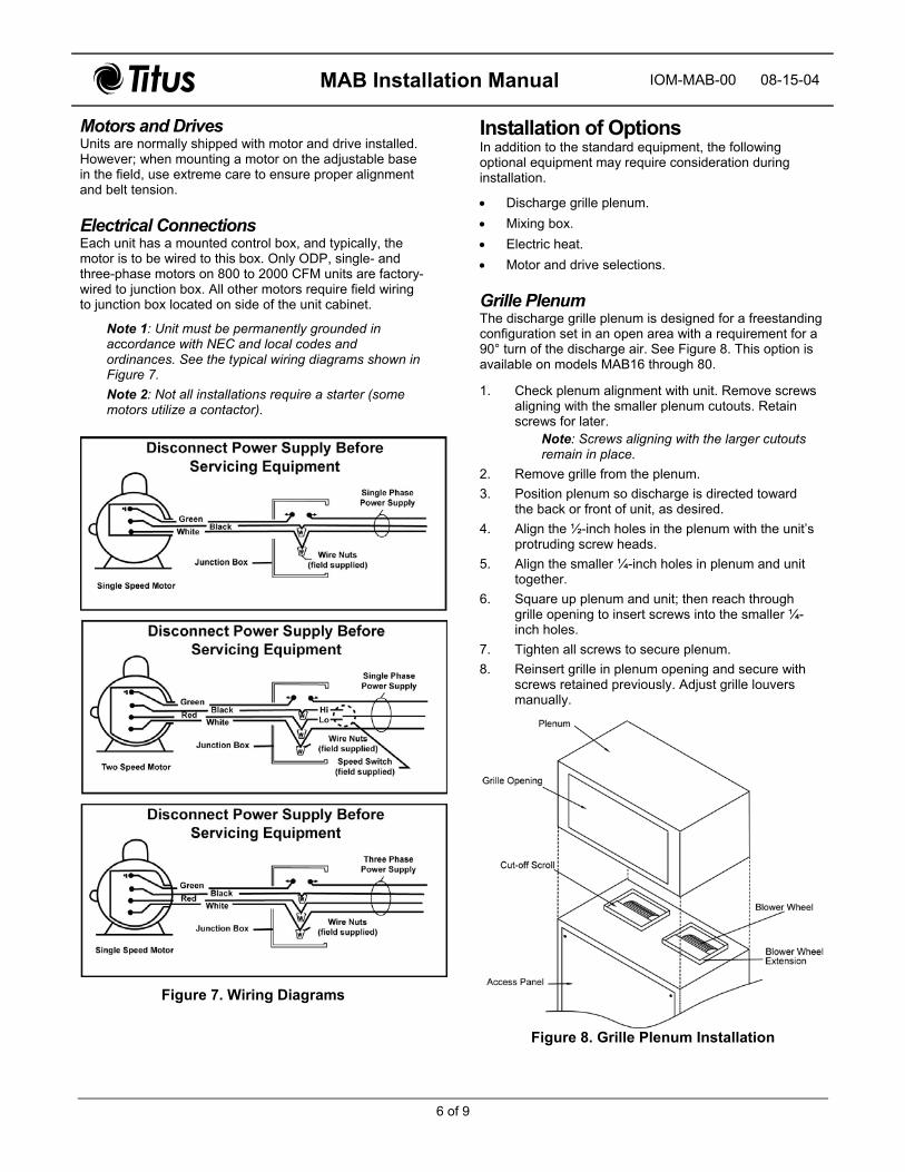
Electrical Connections Each unit has a mounted control box, and typically, the motor is to be wired to this box. Only ODP, single- and three-phase motors on 800 to 2000 CFM units are factory-wired to junction box. All other motors require field wiring to junction box located on side of the unit cabinet.
Note 1: Unit must be permanently grounded in accordance with NEC and local codes and ordinances. See the typical wiring diagrams shown in Figure 7. Note 2: Not all installations require a starter (some motors utilize a contactor).
Figure 7. Wiring Diagrams
Installation of Options In addition to the standard equipment, the following optional equipment may require consideration during installation.
• Discharge grille plenum. • Mixing box. • Electric heat. • Motor and drive selections.
Grille PlenumThe discharge grille plenum is designed for a freestanding configuration set in an open area with a requirement for a 90° turn of the discharge air. See Figure 8. This option is available on models MAB16 through 80.
1. Check plenum alignment with unit. Remove screws aligning with the smaller plenum cutouts. Retain screws for later.
Note: Screws aligning with the larger cutouts remain in place.
2. Remove grille from the plenum. 3. Position plenum so discharge is directed toward
the back or front of unit, as desired. 4. Align the ½-inch holes in the plenum with the unit’s
protruding screw heads. 5. Align the smaller ¼-inch holes in plenum and unit
together.6. Square up plenum and unit; then reach through
grille opening to insert screws into the smaller ¼-inch holes.
7. Tighten all screws to secure plenum. 8. Reinsert grille in plenum opening and secure with
screws retained previously. Adjust grille louvers manually.
Figure 8. Grille Plenum Installation

MAB Installation Manual IOM-MAB-00 08-15-04
7 of 9
Mixing Box InstallationPreparation 1.Inspect desired installation location and determine if space provides sufficient work and safety clearances. If space allows, make all sheet metal connections and attachments prior to moving complete assembly to duct connection site. Figure 9 and Table 6 provide unit, mixing boxes, and damper dimensional information.
2.
1. One side of mixing box has two plastic plugs. These plugs may be removed and placed on the opposite end to seal the unused 7/8-inch holes at the opposite cabinet end where the 5/6-inch linkage rods do not extend outward.
3.
4.
2. Choose the cabinet side most accessible for servicing to mount damper motor. Remove bolt for each damper shaft and extend shaft until second hole in shaft aligns with hole in damper blade. Insert bolt. Connect two shafts with the two crank arms and the 5/16-inch linkage rod (furnished with mixing box).
Attach mixing box to unit return-air duct flange. Vertical duct flange connections at unit rear are pre-punched to match pre-punched holes in mixing boxes. Mixing boxes may be mounted for top-rear or bottom-rear connections. After bolting vertical flange, drill holes in horizontal duct flanges. Secure flanges with screws or nuts and bolts.Use field-supplied hardware to connect motor shaft to one of the damper shafts. Connect duct to the 1-inch duct flange provided on mixing box for return and fresh air locations as needed.
Note: Installation steps 1, 2, and 3 may follow Preparation steps 1 and 2, if preferred.
3. Mount damper motor on the selected side of mixing box cabinet by drilling necessary holes and securing with screws or nuts and bolts.
Figure 9. Mixing Box Dimensions
Table 6. Mixing Box Dimensions
Mixing Box Dimensions Model A B C D E F
Damper Ship Wgt. (lbs)
NominalCFM SP Loss
MAB16/20 8 25.5 16 8 9.5 36 (2) 34 x 8 75 2000 0.07 MAB30/40 12 32 20 10 10 48 (2) 46 x 12 131 4000 0.03 MAB60/80 14 45 22 15 16 66 (2) 56 x 14 201 8000 0.04 Note: All dimensions in inches.

MAB Installation Manual IOM-MAB-00 08-15-04
8 of 9
Electric HeatPreparation Some items to consider prior to installing electric heat are as follows:
• Duct materials must be suitable for 250ºF operation. See NFPA 90A and 90B pamphlet.
• Ensure ample room exists in the ductwork. Electric heat must have at least 24 inches of straight duct clearance before an elbow. If 24 inches are unavailable, devices such as turning vanes or baffles may be required. Note: Electric heaters are incompatible with discharge grille plenum.
InstallationUse the following information to install electric heat on MAB models.
1. Position heater element section over the blower wheel of the MAB unit.
Note: Heater baffle must be aligned with the blower cut-off scroll. Heater should be rotated 180 degrees, if necessary to align. This ensures proper blower discharge of air over the heater element.
2. Attach electric heat plenum to MAB unit using #6 or larger sheet metal screws.
Note: Ensure plenum is securely attached to MAB unit only and not to blower wheel extension.
3. Add insulation, if necessary to outside of plenum. Warning: Do not insulate heater box.
Figure 10 shows MAB and electric heat components.
Air Handler Startup Check the following items before startup.
• Ensure all shipping bolts/screws are removed and all other bolts and screws are tight.
• Never assume the voltage and phase on the unit nameplate is the same as the motor wired.
• Check the alignment of the sheaves and ensure the setscrews are tight.
• Check for proper rotation of the blower pulley.
Figure 10. Modular Unit with Electric Heater Components
• Check motor phase and rotation. − Exchanging two of the three leads at the unit
junction box can reverse three-phase motor rotation.
− Exchanging leads inside the motor junction box can reverse the rotation of single-phase motors. Refer to the motor nameplate.
− Not all installations require a starter (some motors utilize a contactor).
• Ensure all filters are installed. Perform filter check with all doors and panels in place.
• Check the amperage draw of the motor. The amperage draw should not exceed the nameplate amps shown on the motor serial plate.

MAB Installation Manual IOM-MAB-00 08-15-04
9 of 9
Operation and Maintenance Read and heed warning and danger notices before operation and maintenance
DANGER DISCONNECT ELECTRICAL POWER TO ALL
CIRCUITS BEFORE SERVICING UNIT. FAILURE TO DO SO MAY RESULT IN PERSONAL INJURY FROM
ELECTRICAL SHOCK OR MOVING PARTS.
Return Air Filters Inspect return air filters on a regular basis (at least monthly). Clean or replace filter(s). Filter can be accessed from either side of unit.
Caution: Always operate unit with a filter and/or filter access door closed to avoid blower motor damage.
CoilThe coil is easily cleaned when dry. To check or clean, remove unit access panel, filter access door and filter(s). Use accepted industry methods for cleaning. Remove all foreign matter from pan and condensate drain line. Check for rust and holes.
Belt and Pulley The following list highlights items to consider for belt and pulley maintenance and adjustment.
• Proper pulley alignment and belt tension must be maintained at all times.
• Reduce speed by adjusting pulley faces so the faces are further apart.
• Increase speed by moving the faces closer together. • Check pulley setscrews and bolts.
Motor Proper lubrication is essential to long motor life. Use electric motor oil or SAE20 non-detergent oil. Tighten motor mount bracket and base bolts.
Note: Avoid over-oiling the motor. If a motor is over-oiled, the oil may run down the motor shaft and splatter.
BlowerPeriodically check bearing for wear. Replace as required.
Check wheel for dirt accumulation and clean as required.
AbbreviationsThe following table lists the abbreviations found within this document.
Abbrev. Term CFM cubic feet per minute F.P.T. Female pipe thread lbs pounds OD outside diameter PVC polyvinyl chloride SAE Society of automotive Engineers SP static pressure SWT sweat wgt. weight