Embed Size (px)
Citation preview

VARIABLE SPEED ECM MODULAR MULTI-POSITION AIR HANDLERSMODELS: MVC SERIES
INSTALLATION MANUALISO 9001
Certified QualityManagement System
LIST OF SECTIONSGENERAL . . . . . . . . . . . . . . . . . . . . . . . . . . . . . . . . . . . . . . . . . . . . . .1SAFETY . . . . . . . . . . . . . . . . . . . . . . . . . . . . . . . . . . . . . . . . . . . . . . . .1UNIT INSTALLATION . . . . . . . . . . . . . . . . . . . . . . . . . . . . . . . . . . . . .2DUCT WORK AND CONNECTIONS . . . . . . . . . . . . . . . . . . . . . . . . .5ELECTRIC HEATER INSTALLATION . . . . . . . . . . . . . . . . . . . . . . . .6LINE POWER CONNECTIONS . . . . . . . . . . . . . . . . . . . . . . . . . . . . . .7LOW VOLTAGE CONTROL CONNECTIONS . . . . . . . . . . . . . . . . . .8
REQUIRED CONTROL SET-UP . . . . . . . . . . . . . . . . . . . . . . . . . . . 10AIRFLOW AND COMFORT SETTING SELECTION . . . . . . . . . . . . 11UNIT DATA . . . . . . . . . . . . . . . . . . . . . . . . . . . . . . . . . . . . . . . . . . . 12MAINTENANCE . . . . . . . . . . . . . . . . . . . . . . . . . . . . . . . . . . . . . . . . 17AIR SYSTEM ADJUSTMENT . . . . . . . . . . . . . . . . . . . . . . . . . . . . . 17WIRING DIAGRAM . . . . . . . . . . . . . . . . . . . . . . . . . . . . . . . . . . . . . 18START UP SHEET . . . . . . . . . . . . . . . . . . . . . . . . . . . . . . . . . . . . . . 21
LIST OF FIGURESReturn Air Duct Attachment . . . . . . . . . . . . . . . . . . . . . . . . . . . . . . . . .2Typical Installation . . . . . . . . . . . . . . . . . . . . . . . . . . . . . . . . . . . . . . . .3Coil and Air Handler Attachment Details . . . . . . . . . . . . . . . . . . . . . . .3Gasket Location . . . . . . . . . . . . . . . . . . . . . . . . . . . . . . . . . . . . . . . . . .4Dimensions & Duct Connection Dimensions . . . . . . . . . . . . . . . . . . . .4Typical Horizontal Installation . . . . . . . . . . . . . . . . . . . . . . . . . . . . . . .5Duct Attachment . . . . . . . . . . . . . . . . . . . . . . . . . . . . . . . . . . . . . . . . . .6Duct Work Transition . . . . . . . . . . . . . . . . . . . . . . . . . . . . . . . . . . . . . .6Line Power Connections . . . . . . . . . . . . . . . . . . . . . . . . . . . . . . . . . . .7
Air Handler Control Board – Communications Connections . . . . . . . . 7Cooling Models with and without Electric Heat Wiring . . . . . . . . . . . . 9Two-Stage Heat Pump Wiring . . . . . . . . . . . . . . . . . . . . . . . . . . . . . . 9Air Handler with Communicating AC or HP . . . . . . . . . . . . . . . . . . . 10Multi-wire Terminal Connection . . . . . . . . . . . . . . . . . . . . . . . . . . . . 10Duct Static Measurements . . . . . . . . . . . . . . . . . . . . . . . . . . . . . . . . 17Wiring Diagram - ECM - Single Phase Heat Kits . . . . . . . . . . . . . . . 18Wiring Diagram - Three Phase Heat Kits 208-230V . . . . . . . . . . . . . 19
LIST OF TABLESDimensions . . . . . . . . . . . . . . . . . . . . . . . . . . . . . . . . . . . . . . . . . . . . .4Low Voltage Connections . . . . . . . . . . . . . . . . . . . . . . . . . . . . . . . . . .8Fault Codes . . . . . . . . . . . . . . . . . . . . . . . . . . . . . . . . . . . . . . . . . . . .10Heat Relays . . . . . . . . . . . . . . . . . . . . . . . . . . . . . . . . . . . . . . . . . . . .11Comfort Setting Selection . . . . . . . . . . . . . . . . . . . . . . . . . . . . . . . . .11Physical and Electrical Data - Cooling Only . . . . . . . . . . . . . . . . . . . .12Electrical Data - Cooling Only . . . . . . . . . . . . . . . . . . . . . . . . . . . . . .12Electrical Heat - Minimum Fan Speed . . . . . . . . . . . . . . . . . . . . . . . .12
KW & MBH Conversions - For Total Power Input Requirement . . . . 13Electric Heat Performance Data: 208/230-1-60 & 208/230-3-60 . . . 13Electrical Data For Single Source Power Supply: 208/230-1-60 . . . 13Electrical Data For Multi-source Power Supply: 208/230-1-60 . . . . . 14Electrical Data For Single Source Power Supply: 208/230-3-60 . . . 15Electrical Data For Multi-source Power Supply: 208/230-3-60 . . . . . 15Air Flow Data (CFM) . . . . . . . . . . . . . . . . . . . . . . . . . . . . . . . . . . . . . 16
SECTION I: GENERALThe MVC modular air handler series provides the flexibility forinstallation in any position. This unit may be used for upflow, downflow,horizontal right, or horizontal left applications.These units may be located in a closet, utility room, attic, crawl space,or basement. These versatile models may be used for cooling or heatpump operation with or without electric heat or indoor coil.Top or side power and control wiring, color coded leads for controlwiring, easy to install drain connections, and electric heaters allcombine to make the installation easy and minimize installation cost.Electric heat kits are available as field installed accessories. Singlephase kits are available from 2.5 kW to 25 kW. 208-230 volt threephase kits are available from 10kW to 25kW.
SECTION II: SAFETYThis is a safety alert symbol. When you see this symbol onlabels or in manuals, be alert to the potential for personalinjury.
Understand and pay particular attention to the signal words DANGER,WARNING, or CAUTION. DANGER indicates an imminently hazardous situation, which, if notavoided, will result in death or serious injury.WARNING indicates a potentially hazardous situation, which, if notavoided, could result in death or serious injury.
CAUTION indicates a potentially hazardous situation, which, if notavoided may result in minor or moderate injury. It is also used toalert against unsafe practices and hazards involving only propertydamage.
WARNINGFIRE OR ELECTRICAL HAZARDFailure to follow the safety warnings exactly could result in seriousinjury, death or property damage. A fire or electrical hazard may resultcausing property damage, personal injury or loss of life.
WARNINGThe air handler area must not be used as a broom closet or for any otherstorage purposes, as a fire hazard may be created. Never store itemssuch as the following on, near or in contact with the furnace.
1. Spray or aerosol cans, rags, brooms, dust mops, vacuum clean-ers or other cleaning tools.
2. Soap powders, bleaches, waxes or other Cleaning compounds;plastic items or containers; gasoline, kerosene, cigarette lighterfluid, dry cleaning fluids or other volatile fluid.
3. Paint thinners and other painting compounds.4. Paper bags, boxes or other paper products
Never operate the air handler with the blower door removed. To do socould result in serious personal injury and/or equipment damage.
!
!
5169038-UIM-B-0216
5169038-UIM-B-0216
SAFETY REQUIREMENTS1. Failure to carefully read and follow all instructions in this manual
can result in air handler malfunction, death, personal injury and/orproperty damage.
2. This air handler should be installed in accordance with all nationaland local building/safety codes and requirements, local plumbing orwastewater codes, and other applicable codes.
3. This air handler should be installed only in a location and positionspecified in the “Unit Installation” section of this Instruction Manual.
4. The air handler is not to be used for temporary heating of buildingsor structures under construction.
5. Always install the air handler to operate within the air handler’sintended maximum outlet air temperature.
6. The unit rating plate displays the air handler model number. Theunit dimensions for the supply air plenum are provided in Figure 5and Table 1 of this Instruction Manual. The plenum must beinstalled according to the instructions. The return air duct attach-ment is shown in Figure 1.
7. Clearance from combustible material is provided under “Clear-ances” in the “Unit Installation” section.
8. It is necessary to maintain clearances for servicing. Access must beallowed for electric heaters and blower.
9. The unit rating plate and power supply must be verified to ensurethat the electrical characteristics match.
10. Air handler shall be installed so the electrical components are pro-tected from water.
11. Installing and servicing heating/cooling equipment can be hazard-ous due to the electrical components. Only trained and licensedpersonnel should install, repair, or service heating/cooling equip-ment. Unlicensed service personnel can perform basic mainte-nance functions such as cleaning and replacing the air filters. Whenworking on heating/cooling equipment, the precautions in the man-uals and on the labels attached to the unit and other safety precau-tions must be observed as applicable.
12. These instructions cover minimum requirements and conform toexisting national standards and safety codes. In some instancesthese instructions exceed certain local codes and ordinances,especially those who have not kept up with changing residentialand non-HUD modular home construction practices. These instruc-tions are required as a minimum for a safe installation.
INSPECTIONAs soon as a unit is received, it should be inspected for possible dam-age during transit. If damage is evident, the extent of the damageshould be noted on the carrier’s freight bill. A separate request forinspection by the carrier’s agent should be made in writing. Also, beforeinstallation the unit should be checked for screws or bolts, which mayhave loosened in transit. There are no shipping or spacer bracketswhich need to be removed.All accessories such as heater kits and indoor coils should be deter-mined to be available. Installation of these accessories or field conver-sion of the unit should be accomplished before setting the unit in placeor connecting any wiring, ducts or piping.
SECTION III: UNIT INSTALLATION
UNIT SIZING1. The size of the unit should be based on an acceptable heat loss or
gain calculation for the structure. The ACCA – Manual J or otherapproved methods may be used. Reference Figure 5 and Table 1.
2. Only connect the air handler to a duct system which has an externalstatic pressure within the allowable range.
3. Airflow must be within the minimum and maximum limits approvedfor electric heat, indoor coils and outdoor units.
4. When an air handler is installed so that supply ducts carry air circu-lated by the air handler to areas outside the space containing theair handler, the return air shall also be handled by duct(s) sealed tothe air handler casing and terminating in the space to be cooled/heated.
5. Refer to the unit rating plate for the air handler model number, andthen see the dimensions page of this instruction for supply air ple-num dimensions. The plenum must be installed according to theinstructions.
6. The installer must check available supply power and verify that it iswithin the normal operating voltage range for the unit. The accept-able voltage range for these units is as follows:
WARNINGImproper installation, adjustment, alteration, or maintenance may cre-ate a condition where the operation of the product could cause per-sonal injury or property damage. Refer to this manual for assistance,or for additional information, consult a qualified contractor, installer, orservice agency.
CAUTIONThis product must be installed in strict compliance with the installationinstructions and any applicable local, state, and national codesincluding, but not limited to building, electrical, and mechanical codes.
CAUTIONThese air handlers should be transported & handled in an upright,upflow position. Failure to do so may result in unit damage and per-sonal injury. Configuration conversions should be done at site ofinstallation.
!
!
!
FIGURE 1: Return Air Duct Attachment
Entering Air Temperature LimitsWet Bulb Temp.°F Dry Bulb Temp. °F
Min. Max. Min. Max.57 72 65 95
Air Handler Voltage Normal Operating 1 Voltage Range
1. Rated in accordance with ARI Standard 110, utilization range “A”.
208-230-1-60 187-253
SIDE VIEW
RETURN AIRDUCT
A0398-001
When attaching duct work withscrews - keep screws within 5/8”of sides and back of air handler.
2 Johnson Controls Unitary Products

5169038-UIM-B-0216
CLEARANCES Clearances must be taken into consideration, and provided for asfollows:1. Maintenance and servicing access - minimum 36” from front of unit
recommended for blower motor / coil replacement.2. The duct work connected to this unit is designed for zero clearance
to combustible materials.3. A combustible floor base accessory is available for downflow appli-
cations of this unit, if required by local code.
LOCATIONLocation is usually predetermined. Check with owner’s or dealer’sinstallation plans. If location has not been decided, consider thefollowing in choosing a suitable location:1. Select a location with adequate structural support, space for service
access, and clearance for air return and supply duct connections.2. It is not recommended to use hanging brackets to wall mount this
air handler unit.3. Normal operating sound levels may be objectionable if the air han-
dler is placed directly over some rooms such as bedrooms, study,etc.
4. If using the air handler unit with an indoor coil, select a location thatwill permit installation of condensate line to open drain or outdoorsallowing condensate to drain away from structure.
5. When an indoor coil is installed in an attic or above a finished ceil-ing, an auxiliary drain pan should be provided under the air handleras is specified by most local building codes.
6. Proper electrical supply must be available.7. If unit is located in an area of high humidity (i.e. an unconditioned
garage or attic), nuisance sweating of casing may occur. On theseinstallations, unit duct connections and other openings should beproperly sealed, and a wrap of 2” fiberglass insulation with a vaporbarrier should be used.
AIR HANDLER CONFIGURATIONThese air handler units are supplied ready to be installed in an upflow,downflow, horizontal right or horizontal left position. Refer to Figure 2.The unit requires no conversion procedures.
AIR HANDLER AND COIL UPFLOW, DOWNFLOW, AND HORIZONTAL POSTIONS 1. Apply neoprene gasket to the return air end of air handler.2. Attach three tie plates to external sides and back of air handler cas-
ing using screws. Refer to Figure 3.3. Position blower casing over appropriate coil opening (depending on
configuration). Refer to Figure 2.4. Attach the three tie plates to coil casing using screws. Refer to Fig-
ure 3.5. Remove coil access panel and coil filter door.6. Slide the coil out of the coil cabinet, and set coil to the side.7. Locate 2” wide foam gasket.8. Apply foam gasket over the air handler and coil mating seams on
the interior of both unit sides and back. Refer to Figure 4.9. Slide the coil into the housing, and install the coil access panel.
NOTICEThe primary and secondary drain line must be trapped to allow properdrainage of condensate water. The secondary drain line should bepiped to a location that will give the occupant a visual warning that theprimary drain is clogged. If the secondary drain line is not used, itmust be capped.
FIGURE 2: Typical Installation
FIGURE 3: Coil and Air Handler Attachment Details
A0346-001
UPFLOW DOWNFLOW
HORIZONTAL RIGHT
HE
AT
HORIZONTAL LEFT
HEAT
HEAT
HE
AT
HE
AT
A0347-001
OUTER TIE PLATE (3 PLACES)
AIRHANDLER
COIL
NOTE:External tie platesare installed on bothsides and the back
Johnson Controls Unitary Products 3

5169038-UIM-B-0216
FIGURE 4: Gasket Location
FOAM GASKET
AIR HANDLER
FIGURE 5: Dimensions & Duct Connection Dimensions
E
F
A
A0327-001
SERVICE DISCONNECTPANEL
TOP OUTLETDIMENSIONS
BOTTOM INLETDIMENSIONS
C
D12-3/16”
19-1/8”
B 20-1/2”
21-1/2”
TABLE 1: Dimensions
ME MODELS
Dimensions1 Wiring Knockout Dimensions1, 2
A B C D E FHeight Width Bottom Opening Top Opening Power Control
MVC08BN21 21-1/2 17-1/2 16-1/2 16-1/2
7/8 (1/2)1-3/8 (1)
1-23/32 (1-1/4)7/8 (1/2)
MVC12BN21 21-1/2 17-1/2 16-1/2 16-1/2MVC14DN21 22-1/2 24-1/2 23-1/2 23-1/2MVC16CN21 22-1/2 21 20 20MVC20DN21 22-1/2 24-1/2 23-1/2 23-1/2
1. All dimensions are in inches.2. Actual size (Conduit size).
4 Johnson Controls Unitary Products

5169038-UIM-B-0216
SECTION IV: DUCT WORK AND CONNECTIONS
Air supply and return may be handled in one of several ways bestsuited to the installation. Upflow, horizontal or downflow applicationsmay be used.The vast majority of problems encountered with heating and coolingsystems can be linked to improperly designed or installed duct systems.It is therefore highly important to the success of an installation that theduct system be properly designed and installed.When installing a central air return grille in or near the living space, it isadvisable to design the duct work so that the grille is not in direct linewith the opening in the unit. One or two elbows and acoustical duct linerassures a quieter system. Operation where return air duct is short orwhere sound may be a problem, acoustical duct liner should be usedinside the duct. Use flexible duct connectors to minimize thetransmission of vibration/noise into the conditioned space.
Insulation of duct work is a must where it runs through an unheatedspace during the heating season or through an uncooled space duringthe cooling season. The use of a vapor barrier is recommended toprevent absorption of moisture from the surrounding air into theinsulation. The supply air duct should be properly sized by use of a transition tomatch unit opening. All ducts should be suspended using flexiblehangers and never fastened directly to the structure. Duct work should be fabricated and installed in accordance with localand/or national codes. This includes the standards of the National FireProtection Association for Installation of Air-Conditioning andVentilating Systems, NFPA No. 90B. Duct systems should be designedin accordance with the Air Conditioning Contractors of America (ACCA)– Manual D.
Use flexible duct collars to minimize the transmission of vibration/noiseinto the conditioned space. If electric heat is used, non-flammablematerial must be used. All ducts should be suspended using flexible hangers and neverfastened directly to the structure.
HORIZONTAL SUSPENSIONFor suspension of these units in horizontal applications, it is recom-mended to use angle steel support brackets with threaded rods, sup-porting the units from the bottom, at the locations shown in Figure 6. WARNING
Use only 1/2” screws to connect duct work to bottom of unit.
WARNINGDo not bring in return air from a location which could introduce haz-ardous substances into the airflow.Use 1/2” screws to connect duct work to cabinet. If pilot holes aredrilled, drill only through field duct and unit flange.
CAUTIONThis unit is not designed for non-ducted (freeblow) applications. Donot operate without duct work attached to unit.Equipment should never be operated without filters.
!
!
!
(Cabinet Width) PositionDimensions
H X(17-1/2”) Horizontal Left 40-1/2” – 47-1/2” 20”
(21” thru 24-1/2”) Horizontal Left 43-1/2” – 55-1/2” 21” (17-1/2”) Horizontal Right 40-1/2” – 47-1/2” 20”
(21” thru 24-1/2”) Horizontal Right 43-1/2” – 55-1/2” 21” FIGURE 6: Typical Horizontal Installation
SUSPENSION SUPPORT LOCATIONS FOR HORIZONTAL RIGHT
2” 1-1/2”
MIN. 1-1/2” x 1-1/2”Angle Recommendedlength 26” minimumwith 2” clearance on bothsides of Air Handler
MIN. 3/8”THREADED ROD
H
1”1-1/2”
A0348-002
X
H
SUSPENSION SUPPORT LOCATIONS FOR HORIZONTAL LEFT
X
TIE PLATE
Johnson Controls Unitary Products 5

5169038-UIM-B-0216
DUCT FLANGESThree duct flanges are provided to assist in positioning and attachingduct work to the air handler. These flanges are included in the unit partsbag. With the screws from the parts bag, install one of the duct flanges.Duct flanges have holes on both legs with one leg longer than the other.The longer leg can be used to mate against the air handler so thatdifferent thicknesses of duct board can be made flush with the outersurface of the air handler. Repeat the procedure for the other twoflanges. Refer to Figure 7. If the flanges are not used, they may bediscarded.
UNIT CONNECTIONSThere are several ways to handle the supply and return air ductconnections. The location and sizing of the connections depends on thesituation and the method best suited to the installation. Upflow,horizontal or downflow applications may be used.The supply air duct should be properly sized by use of a transition tomatch unit opening. Refer to Table 1 for air handler unit inlet and outletdimensions.
Duct work that is not designed to match the supply air opening cancause turbulence inside the plenum. This turbulence can change the airflow patterns across the electric heater limit switches. If the factorysuggested transition cannot be fabricated, it is recommended that ablock off plate (approximately 8" high and running the full width of theplenum) be attached to the supply opening. Refer to Figure 8 as avisual aid. The use of this block off plate will enable better air circulationacross the limit switches.
AIR FILTERSReturn air filters are required and must be field supplied. Filtration mustbe accomplished external to the unit..
SECTION V: ELECTRIC HEATER INSTALLATIONIf the air handler requires electric heat, install the electric heat kitaccording to the installation instructions included with the kit. Afterinstalling the kit, mark the air handler nameplate to designate the heaterkit that was installed. If no heater is installed, mark the name plateappropriately to indicate that no heat kit is installed.Use only 6HK Revision C or later heater kits, as listed on air handlername plate and in these Instructions. Use data from Tables 8-15 forinformation on required minimum motor speed tap to be used for heat-ing operation and maximum over-current protection device required aslisted for combination of air handler and heater kit.For Upflow, Downflow and Horizontal left-hand applications, the kits canbe installed without modification. Field modification is required for Horizontal right-hand airflow applica-tion only. Follow instructions with heater for modification.
FIGURE 7: Duct Attachment
FIGURE 8: Duct Work Transition
A0341-001
DUCT FLANGES
(Shipped in bag with coil)
A0332-001
RECOMMENDEDTRANSITION
SUGGESTED LOCATIONOF BLOCK OFF PLATE
CAUTIONUse 1/2” screws to connect duct work to unit.
CAUTIONEquipment should never be operated without filters.
NOTICEIn some horizontal applications, the service disconnects on the elec-tric heat kits must be rotated 180° so the up position of the discon-nect is the ON position. This service disconnect orientation change isrequired by UL1995, Article 26.19 (in reference to all circuit break-ers).
!
!
6 Johnson Controls Unitary Products

5169038-UIM-B-0216
SECTION VI: LINE POWER CONNECTIONSPower may be brought into the unit through the supply air end of theunit (top left when unit is vertical) or the left side panel. Use the holeappropriate to the unit’s orientation in each installation to bring conduitfrom the disconnect. The power lead conduit should be terminated atthe electrical control box. Refer to Tables 7, 11-14 and to the latestedition of the National Electric Code or in Canada the Canadianelectrical Code and local codes to determine correct wire sizing. Tominimize air leakage, seal the wiring entry point at the outside of theunit.All electrical connections to air handlers must be made with copperconductors. Direct connection of aluminum wiring to air handlers isnot approved.
If aluminum conductors are present, all applicable local and nationalcodes must be followed when converting from aluminum to copperconductors prior to connection to the air handler.The chosen conductor and connections all must meet or exceed theamperage rating of the overcurrent protector (service disconnect orfuse) in the circuit.Existing aluminum wire within the structure must be sized correctly forthe application according to National Electric Code and local codes.Caution must be used when sizing aluminum rather than copperconductors, as aluminum conductors are rated for less current thancopper conductors of the same size.
FIGURE 9: Line Power Connections
FIGURE 10: Air Handler Control Board – Communications Connections
LEAVING AIR TEMPSENSOR TERMINALS
FLOAT SWITCHINPUT
HUMIDIFIEROUTPUT
CFMINDICATOR
STATUSINDICATOR BLOWER
SPEEDJUMPERS
HUMIDISTATJUMPER
AC/HP JUMPER
MODELID PLUG
FUSE
COMMPORT
SERVICETOOLPORT
A0405-001
ELECTRONICAIR CLEANER
EAC
Johnson Controls Unitary Products 7
5169038-UIM-B-0216
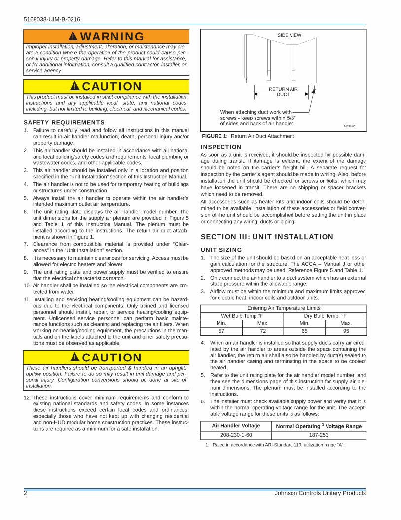
SECTION VII: LOW VOLTAGE CONTROL CONNECTIONSThe 24 volt power supply is provided by an internally wired low voltagetransformer which is standard on all models, However, if the unit is con-nected to a 208 volt power supply, the low voltage transformer must berewired to the 208 volt tap. See the unit wiring label.Remove desired knockout and pierce foil faced insulation to allow wir-ing to pass through. Use as small of a hole as possible to minimize airleakage.Install a 7/8” plastic bushing in the selected hole and keep low voltagewiring as short as possible.To further minimize air leakage, seal the wiring entry point at the out-side of the unit.The field wiring is to be connected with wire connectors to the wiresprovided. Refer to Figures 11 & 12.
Humidity Switch InputThe air handler control is designed to work with a humidity control thatcloses when the humidity is below the set-point. The control is openwhen the humidity is above the set-point. This humidity control may bereferred to as a humidistat or a dehumidistat.The humidity switch controls de-humidification operation of the controlduring cooling operation. The humidity switch should be connected toHUM wire of the control. See Figures 11 & 12.
NOTICEAll wiring must comply with local and national electrical code require-ments. Read and heed all unit caution labels.
NOTICEIt is possible to vary the amount of electric heat turned on during thedefrost cycle of a heat pump. Standard wiring will only bring on thefirst stage of electric heat during defrost. See Table 10 for additionalinformation on heat during defrost cycle.
NOTICEAll wiring must comply with local and national electrical coderequirements. Read and heed all unit caution labels.It is possible to vary the amount of electric heat turned on during thedefrost cycle of a heat pump. Standard wiring will only bring on thefirst stage of electric heat during defrost. See Heat Output and LimitConnections and Table 4 for additional information on heat duringdefrost cycle.
TABLE 2: Low Voltage Connections
Terminal Colors Signals CommentR Red 24 VAC power (fused)G Green Continuous Fan operation
Y/Y2 Yellow Second or full stage compressor operation
Y1 Yellow & Black First stage compressor operation Not used with outdoor units having one stage compressors.W2 Brown Second stage heat operationW1 White First stage heat operationO Orange Reversing valve operation
HUM Purple Humidity switch input
EAC Field Supplied Wiring Electric Air Cleaner Located on P2 connector. There is 24VAC output during indoor blower operation to
energize a pilot duty relay for an electronic air cleaner.
X/L Field Supplied Wiring
Connection point for heat pump fault indicator
This terminal is a connection point only and does not affect air handler control operation.
COM Blue 24 VAC common
8 Johnson Controls Unitary Products

5169038-UIM-B-0216
* Optional dehumidification humidistat switch contacts open on humidity rise.
NOTES:1. “Y/Y2” Thermostat wire must be connected for full CFM and applications requiring 60 second blower off delay for SEER enhancement.2. Move HUM STAT jumper on air handler control board to YES position if humidistat is used.3. For heat pump applications - set AC/HP jumper on air handler control board to the HP position.
.
* Optional dehumidification humidistat switch contacts open on humidity rise.NOTES:1. “Y/Y2” Thermostat wire must be connected for full CFM and applications requiring 60 second blower off delay for SEER enhancement.2. Remove humidistat jumper on air handler control board.3. For heat pump applications - set AC/HP jumper on air handler control board to the HP position.
CONTROL WIRING USING COMMUNICATING CONTROLSThe Communicating System consists of several intelligent communicat-ing components including the Communicating Thermostat Control(touch-screen wall thermostat), variable speed air handler, air condi-tioner (15 and 18 SEER premium air conditioners) or heat pump (13, 15and 18 SEER premium heat pumps), which continually communicatewith each other via a four-wire connection called the A-R-C-B bus.Commands, operating conditions, and other data are passed continu-ally between components over the A-R-C-B bus. See Figure 13. Theresult is a new level of comfort, versatility, and simplicity.In order to use this air handler in full communications (COMM) mode, itMUST be installed with the matching touch-screen CommunicatingControl (wall thermostat) and an outdoor air conditioner or heat pumpwith a fully communicating control.
This air handler may also be used along with the touch-screen Commu-nicating Control and a non-communicating outdoor air conditionerthrough the addition of a communicating AC Control board to the out-door unit. This system allows full communication between the air han-dler, outdoor unit, and touch-screen Communication Control. Use the wiring diagram as shown in Figure 13 to connect the air handlercontrol, touch-screen Communicating Control (wall thermostat) andcommunicating outdoor unit. Be sure that all of the “A+” terminals areconnected together, all of the “B-” terminals are connected together, allof the “C” terminals are connected together and all of the “R” terminalsare connected together. See Figure 13 & 14. When using a fully com-municating system, removal of the low voltage signal connector at P3 isrecommended (C, G, R, etc.). The four small screw terminals in the ter-minal block on the end of the air handler control should be used.
FIGURE 11: Cooling Models with and without Electric Heat Wiring
FIGURE 12: Two-Stage Heat Pump Wiring
Johnson Controls Unitary Products 9

5169038-UIM-B-0216
FLOAT SWITCH INPUTAn optional switch may be connected to the FLT terminals on the con-trol board. This feature is only functional when used with the Communi-cating Control. It is intended for use with a water overflow switch.
LEAVING AIR TEMP SENSOR INPUTA plenum air temperature sensor (thermistor) can be connected to theLAS terminals on the control board. The Communicating Control canthe monitor the temperature of the supply air in the plenum.
SECTION VIII: REQUIRED CONTROL SET-UP
1. Consult system wiring diagram to determine proper thermostatwiring for your system.
2. If using a communicating control and a humidistat is installed,change HUM STAT jumper from NO to YES.
3. Set the MODE jumper to A/C (Air Conditioner) or HP (Heat Pump)position depending on the outdoor unit included with the system.
4. Set airflow and comfort setting jumper to proper positions.
FUNCTIONALITY AND OPERATIONJumper PositionsHum Stat JumperThe HUM STAT jumper configures the control to monitor the humidityswitch input. With the jumper in the NO position, the control will ignorethe HUM input. With the jumper in the YES position, the control willmonitor the HUM input to control the blower speed for de-humidificationduring cooling operation.If the jumper is not present, the control will operate as if the jumper is inthe NO position.AC/HP JumperThe AC/HP jumper configures the control to operate properly with an airconditioner (AC position) or heat pump (HP position). With the jumper inthe AC position, the control will treat any “Y” call as a cooling call. Withthe jumper in the HP position, the O input signal is received from theroom thermostat. This allows the control to recognize whether in theheating or cooling mode and energizes the 24 VAC HUM output whenblower is on and a first stage heating call is present.If the jumper is not present, the control will operate as if the jumper is inthe HP position.Airflow and Comfort Setting JumpersSee separate section.
Status and Fault CodesThe control includes an LED that displays status and fault codes. Thesecodes are shown in Table 3. The control will display the fault codes untilpower is removed from the control or the fault condition is no longerpresent.
CAUTIONIf any field-supplied wiring is to be connected to the control board,such as will be the case if the Communicating Control is used or if ahumidistat, float switch or leaving air temperature switch are used,the additional wires MUST be routed through the hole at the lower leftof the control box. DO NOT add any additional holes to the controlbox. After attaching the additional wires to the board, the remaininghole around the wires must be plugged with the sealant putty suppliedor with a suitable waterproof sealant. FAILURE TO SEAL THIS HOLEMAY ALLOW WATER TO ENTER THE CONTROL BOX AND DAM-AGE THE CONTROL BOARD.
FIGURE 13: Air Handler with Communicating AC or HP
IMPORTANTDo not place more than one wire under any single communicationterminal screw (there are four communication terminal screws). Ifmore than one wire must be connected to a terminal screw, attachonly the terminal end of a one wire pigtail no longer than 6“, anduse a wire connector to connect the other end of the pigtail to theother wires. Failure to do this will result in nuisance communicationerror faults. See Figure 14.
FIGURE 14: Multi-wire Terminal Connection
!
A+
R
C
B-
A+
R
C
B-
A+
R
C
B-
R
G
Y/Y2
Y1
W2
W1
O
HUM
COM
TOUCH SCREENCOMMUNICATING
CONTROL
AIR HANDLERCOMMUNICATING
CONTROL
AC/HEAT PUMPCOMMUNICATING
CONTROL
EAC
A0409-001
OUTDOOR UNIT
INDOOR UNIT
WIRECONNECTOR
THERMOSTAT
TERMINALSCREW
NOTE:
Ensure only one wire under
terminal screw.
To connect more than one wire:
A+
R
C
B-
AIR HANDLERCOMMUNICATINGCONTROL BOARD
1. Connect only terminal end of” wire pigtail.
2. Use wire connector to connectother end of pigtailto other wires.
A0237-001
IMPORTANTThe following steps must be taken at the time of installation to insureproper system operation.
TABLE 3: Fault Codes
Fault or Status Condition LED1 (RED)Flash Code
StatusNo power to control OFFInternal control fault ON2 sec on 2 sec off heartbeat Normal0.1 sec on, 0.1 sec off Test modeCall for heat and cool at the same time 7Model Plug Not inserted 8Internal fault self-corrected, attempting normal operation 9
10 Johnson Controls Unitary Products

5169038-UIM-B-0216
HUM OUT OutputThe HUM OUT output can be used to drive an external relay or solenoid(24 VAC coil) to control a humidifier. The output is energized when thecontrol has a thermostat call for heating (heat pump or electric heat).
Heat Output The control is connected to the heater relays using pins 4,5, & 6 of con-nector P1. The relay outputs are 24 VAC.The control energizes the heat relays as shown in Table 4.
Depending on the heat kit installed in the air handler, the control pro-vides the flexibility to configure the amount of heat delivered with thefirst stage heating call. As an example, when the control’s W1 input isconnected to the room thermostat’s first stage heat signal, a call for firststage heat will energize one heating element (HT1). If the control’s W2input is connected to the room thermostat’s first stage heat signal, a callfor first stage heat will energize one heating element (HT2). With eitherconfiguration, the control will energize two heating elements (HT1, andHT2) when it receives a first and second stage heat input from the ther-mostat.Wiring Related FaultsIf the control receives a simultaneous call for heating and cooling (faultcode 7), the control will perform both heating and cooling operations.
SECTION IX: AIRFLOW AND COMFORT SETTING SELECTIONAIRFLOW SELECTIONWhen not using communicating functionality, the airflow and comfortsetting selection jumpers must be set properly at the time of installationfor proper system operation. Place jumpers in the proper locationsbased on the information shown in Tables 8 & 15. Inputs to air handler control board are passed to the motor which deter-mines the target CFM to be delivered. The following inputs will producethe CFM per the appropriate table and selected tap settings.
These variable speed air handlers are designed to deliver constant air-flow (CFM) regardless of the external static pressure (ESP) in theductwork. Therefore, if too many supply registers are closed, a filterbecomes clogged, or there is a restriction in the ductwork, the motor willautomatically operate at a higher speed to compensate for the higherESP. This may result in a higher operating sound level and motor dam-age.To Set Cooling Airflow:Refer to the outdoor unit technical guide for the recommended airflowwith the matching indoor coil. Refer to Table 15 for the possible highspeed cooling and heat pump airflow selections.Find the recommended system airflow in Table 15 for the installed airhandler model and outdoor unit.Select the COOL airflow you need from Table 15. Set the COOL andADJUST Jumpers on the control as indicated in Table 15.
To Set Heat Pump Airflow:The heat pump airflow setting is the same as the cooling airflow setting.No additional airflow setting is required. However, you must set the AC/HP jumper to the HP position for proper system operation (See Figure10).To Set Electric W1 Heat Airflow:The blower speed required for 1st stage electric heat is different thancooling. Refer to Table 15 for the possible CFM selections. Refer toTable 8 for the minimum required airflow for the electric heater installed.Find the desired airflow in Table 15 for low heat. Set the HEAT jumperon the control as indicated in Table 15.To Set W2 Electric Heat Airflow:Airflow for any W2 input, which is for Stages 2 & 3 of electric heat, is theindicated CFM for high heat tap selection on Table 15.
Blower Ramp-Up /Ramp-Down:To minimize the sound made by the blower when it speeds up or slowsdown, the blower will slowly ramp up or down from one speed toanother. Changes in blower speed during A/C or heat pump heating cantake up to 30 seconds. Changes in blower speed during electric resis-tance heating can take up to 15 seconds.
COMFORT SETTINGS
NormalThe normal setting provides a ramp-up from zero airflow to full capacityand a ramp-down from full capacity back to zero airflow.
HumidThe humid setting is best-suited for installations where the humidity isfrequently very high during cooling season, such as in the southern partof the country. On a call for cooling, the blower will ramp up to 50% offull capacity and will stay there for two minutes, then will ramp up to82% of full capacity and will stay there for five minutes, and then willramp up to full capacity, where it will stay until the wall thermostat is sat-isfied. DryThe dry setting is best suited to parts of the country where excessivehumidity is not generally a problem, where the summer months are usu-ally dry. On a call for cooling the motor will ramp up to full capacity andwill stay there until the thermostat is satisfied. At the end of the coolingcycle, the blower will ramp down to 50% of full capacity where it will stayfor 60 seconds. Then it will ramp down to zero.TemperateThe temperate setting is best suited for most of the country, where nei-ther excessive humidity nor extremely dry conditions are the norm. Ona call for cooling, the motor will ramp up to 63% of full capacity and willstay there for 90 seconds, then will ramp up to full capacity. At the endof the cooling cycle, the motor will ramp down to 63% of full capacityand will stay there for 30 seconds, then will ramp down to zero.
TABLE 4: Heat Relays
Input Heat Relay OutputW1 HT1W2 HT2
W1 and W2 HT1 and HT2
NOTICEIncorrect airflow and comfort settings may result in decreased systemefficiency and performance.
CAUTIONDO NOT change the ADJUST tap position on the control as this willchange your cooling airflow previously selected.
TABLE 5: Comfort Setting Selection
DELAY TAP COMFORT SETTINGA NormalB HumidC DryD Temperate
!
Johnson Controls Unitary Products 11

5169038-UIM-B-0216
SECTION X: UNIT DATATABLE 6: Physical and Electrical Data - Cooling Only
Models MVC08B MVC12B MVC14D MVC16C MVC20D Blower - Diameter x Width 10 x 8 10 x 8 11 x 10 11 x 10 11 x 10
MotorHP 1/3 HP 1/2 HP 1/2 HP 3/4 HP 3/4 HP
Nominal RPM 1050 1050 1050 1050 1050 Voltage 208/230 208/230 208/230 208/230 208/230
Full Load Amps @230V 2.9 4.5 4.5 7.0 7.0
Filter1
Type DISPOSABLE OR PERMANENTSize 16 x 20 x 1 16 x 20 x 1 22 x 20 x 1 20 x 20 x 1 22 x 20 x 1
Bottom Rack Kit 1BR01117 1BR01117 1BR01124 1BR01121 1BR01124
Permanent Type Kit 1PF0601 1PF0601 1PF0603 1PF0602 1PF0603
Shipping / Operating Weight (lbs.) 52/51 52/51 75/74 68/67 75/74
1. Field supplied.
TABLE 7: Electrical Data - Cooling Only
Models Motor FLA1 Minimum Circuit AmpacityMOP2
208V 230V 208V 230VMVC08B 3.0 2.9 3.8 3.6 15
MVC12B/MVC14D 5.0 4.5 6.3 5.6 15
MVC16C/MVC20D 7.3 7.0 9.1 8.8 15
1. FLA = Full Load Amps2. MOP = Maximum Overcurrent Protection device; must be HACR type service disconnect or time delay fuse. Refer to the latest edition of the National Electric Code
or in Canada the Canadian electrical Code and local codes to determine correct wire sizing.
TABLE 8: Electrical Heat - Minimum Fan Speed
Heater Kit Models1,2,3 Nom. kW@240V
Air Handler ModelsMVC08B MVC12B MVC14D MVC16C MVC20D
6HK(0,1)6500206 2.4kW Med Lo (D) Med Lo (D) Med Lo (D) Med Lo (D) Med Lo (D)6HK(0,1)6500506 4.8kW Med (C) Med Lo (D) Med Lo (D) Med Lo (D) Med Lo (D)6HK(0,1)6500806 7.7kW Med Hi (B) Med Lo (D) Med (C) Med Lo (D) Med Lo (D)6HK(0,1)6501006
6HK36501025 9.6kW Med Hi (B) Med Lo (D) Med (C) Med Lo (D) Med Lo (D)
6HK(1,2)6501306 12.5kW Hi (A) Med Hi (B) Med (C) Med Lo (D) Med Lo (D)6HK(1,2)6501506
6HK36501525 14.4kW – Hi (A) Med (C) Med Lo (D) Med Lo (D)
6HK(1,2)65018066HK36501825 17.3kW – Hi (A) Med Hi (B) Med (C) Med (C)
6HK(1,2)65020066HK46502025 19.2kW – Hi (A) – Med Hi (B) Med (C)
6HK(1,2)65025066HK46502525 24kW – – – – Med (C)
1. (0,1) - 0 = no service disconnect OR 1 = with service disconnect.2. (1,2) - 1 = with service disconnect, no breaker jumper bar OR 2 = with service disconnect & breaker jumper bar.3. 6HK3 = 3-Phase with terminal block connectors only, 6HK4 = 3-Phase with service disconnect.
12 Johnson Controls Unitary Products

5169038-UIM-B-0216
TABLE 9: KW & MBH Conversions - For Total Power Input RequirementFor a power distribution voltage that is different than the provided nominal voltage, multiply the kW and MBH data from the table by theconversion factor in the following table.
DISTRIBUTION POWER NOMINAL VOLTAGE CONVERSION FACTOR208V 240V 0.75220V 240V 0.84230V 240V 0.92
TABLE 10: Electric Heat Performance Data: 208/230-1-60 & 208/230-3-60
Heater Models1,2,3
Nominal kW @240V
Total Heat4 kW Staging
kW MBH W1 Only W1 + W2
208V 230V 208V 230V 208V 230V 208V 230V
1PH
6HK(0,1)6500206 2.4 1.8 2.2 6.2 7.5 1.8 2.2 1.8 2.26HK(0,1)6500506 4.8 3.6 4.4 12.3 15 3.6 4.4 3.6 4.46HK(0,1)6500806 7.7 5.8 7.1 19.7 24.1 5.8 7.1 5.8 7.16HK(0,1)6501006 9.6 7.2 8.8 24.6 30.1 7.2 8.8 7.2 8.86HK(1,2)6501306 12.5 9.4 11.5 32 39.2 3.1 3.8 9.4 11.56HK(1,2)6501506 14.4 10.8 13.2 36.9 45.1 3.6 4.4 10.8 13.26HK(1,2)6501806 17.3 13 15.9 44.3 54.2 6.5 7.9 13 15.96HK(1,2)6502006 19.2 14.4 17.6 49.2 60.2 7.2 8.8 14.4 17.66HK(1,2)6502506 24 18 22 61.5 75.2 7.2 8.8 18 22
3PH
6HK36501025 9.6 7.2 8.8 24.6 30.1 7.2 8.8 7.2 8.86HK36501525 14.4 10.8 13.2 36.9 45.1 10.8 13.2 10.8 13.26HK36501825 17.3 13 15.9 44.3 54.2 13 15.9 13 15.96HK46502025 19.2 14.4 17.6 49.2 60.2 7.2 8.8 14.4 17.66HK46502525 24 18 22 61.5 75.2 9 11 18 22
1. (0,1) - 0 = no service disconnect OR 1 = with service disconnect.2. (1,2) - 1 = with service disconnect, no breaker jumper bar OR 2 = with service disconnect & breaker jumper bar. 3. 6HK3 = 3-Phase with terminal block connectors only, 6HK4 = 3-Phase with service disconnect.4. For different power distributions, see conversion table on Page 5.
TABLE 11: Electrical Data For Single Source Power Supply: 208/230-1-60
Air Handler Models
Heater Models1,2
HeaterAmps@240V
Field WiringMin. Circuit Ampacity MOP.3
208V 230V 208V 230V
MVC08B
6HK(0,1)6500206 10 14.6 15.6 15 206HK(0,1)6500506 20 25.4 27.5 30 306HK(0,1)6500806 32 38.6 42.2 40 456HK(0,1)6501006 40 47.0 51.5 50 606HK(1,2)6501306 52 60.2 66.1 70 70
MVC12B
6HK(0,1)6500206 10 17.1 17.6 20 206HK(0,1)6500506 20 27.9 29.5 30 306HK(0,1)6500806 32 41.1 44.2 45 456HK(0,1)6501006 40 49.5 53.5 50 606HK(1,2)6501306 52 62.7 68.1 70 706HK(1,2)6501506 60 71.2 77.4 80 806HK(1,2)6501806 72 84.4 92.0 90 1006HK(1,2)6502006 80 92.8 101.3 100 110
MVC14D
6HK(0,1)6500206 10 17.1 17.6 20 206HK(0,1)6500506 20 27.9 29.5 30 306HK(0,1)6500806 32 41.1 44.2 45 456HK(0,1)6501006 40 49.5 53.5 50 606HK(1,2)6501306 52 62.7 68.1 70 706HK(1,2)6501506 60 71.2 77.4 80 806HK(1,2)6501806 72 84.4 92.0 90 100
For notes, see Page 14.
Johnson Controls Unitary Products 13

5169038-UIM-B-0216
MVC16C
6HK(0,1)6500206 10 19.9 20.7 25 256HK(0,1)6500506 20 30.8 32.7 35 356HK(0,1)6500806 32 44.0 47.3 45 506HK(0,1)6501006 40 52.4 56.6 60 606HK(1,2)6501306 52 65.6 71.3 70 806HK(1,2)6501506 60 74.0 80.5 80 906HK(1,2)6501806 72 87.3 95.2 90 1006HK(1,2)6502006 80 95.7 104.4 100 110
MVC20D
6HK(0,1)6500206 10 19.9 20.7 25 256HK(0,1)6500506 20 30.8 32.7 35 356HK(0,1)6500806 32 44.0 47.3 45 506HK(0,1)6501006 40 52.4 56.6 60 606HK(1,2)6501306 52 65.6 71.3 70 806HK(1,2)6501506 60 74.0 80.5 80 906HK(1,2)6501806 72 87.3 95.2 90 1006HK(1,2)6502006 80 95.7 104.4 100 1106HK(1,2)6502506 100 117.3 128.3 125 150
1. (0,1) - maybe 0 (no service disconnect) or 1 (with service disconnect).2. (1,2) maybe 1 (with service disconnect, no breaker jumper bar) or 2 (with service disconnect & breaker jumper bar).3. MOP = Maximum Overcurrent Protection device; must be HACR type circuit breaker or time delay fuse. Refer to the latest edition of the
National Electric Code or in Canada the Canadian electrical Code and local codes to determine correct wire sizing.
TABLE 11: Electrical Data For Single Source Power Supply: 208/230-1-60 (Continued)
Air Handler Models
Heater Models1,2
HeaterAmps@240V
Field WiringMin. Circuit Ampacity MOP.3
208V 230V 208V 230V
TABLE 12: Electrical Data For Multi-source Power Supply: 208/230-1-60
Air Handler Models
Heater Models
HeaterAmps @240V
Min. Circuit Ampacity MOP.1
208V 230V 208V 230VCircuit Circuit
1st3 2nd 3rd 1st3 2nd 3rd 1st3 2nd 3rd 1st3 2nd 3rdMVC08B 6HK16501306 52 22.5 37.6 - 24.4 41.5 - 25 40 - 25 45 -
MVC12B
6HK16501306 52 25.0 37.6 – 26.4 41.5 – 25 40 – 30 45 –6HK16501506 60 27.9 43.3 – 29.6 47.9 – 30 45 – 30 50 –6HK16501806 72 45.3 39.0 – 48.8 43.1 – 50 40 – 50 45 –6HK16502006 80 49.6 43.3 – 53.5 47.9 – 50 45 – 60 50 –
MVC14D
6HK16501306 52 25.0 37.6 – 26.4 41.5 – 25 40 – 30 45 –6HK16501506 60 27.9 43.3 – 29.6 47.9 – 30 45 – 30 50 –6HK16501806 72 45.3 39.0 – 48.8 43.1 – 50 40 – 50 45 –6HK16502006 80 49.6 43.3 – 53.5 47.9 – 50 45 – 60 50 –
MVC16C
6HK16501306 52 27.9 37.6 – 29.5 41.5 – 30 40 – 30 45 –6HK16501506 60 30.8 43.3 – 32.7 47.9 – 35 45 – 35 50 –6HK16501806 72 48.1 39.0 – 51.9 43.1 – 50 40 – 60 45 –6HK16502006 80 52.5 43.3 – 56.7 47.9 – 60 45 – 60 50 –
MVC20D
6HK16501306 52 27.9 37.6 – 29.5 41.5 – 30 40 – 30 45 –6HK16501506 60 30.8 43.3 – 32.7 47.9 – 35 45 – 35 50 –6HK16501806 72 48.1 39.0 – 51.9 43.1 – 50 40 – 60 45 –6HK16502006 80 52.5 43.3 – 56.7 47.9 – 60 45 – 60 50 –6HK16502506 100 52.5 43.3 21.7 56.7 47.9 24.0 60 45 25 60 50 25
1. MOP = Maximum Overcurrent Protection device; must be HACR type circuit breaker or time delay fuse. The 1st circuit includes blower motor amps. Refer to the latest edition of the National Electric Code or in Canada the Canadian electrical Code and local codes to determine correct wire sizing.
14 Johnson Controls Unitary Products

5169038-UIM-B-0216
TABLE 13: Electrical Data For Single Source Power Supply: 208/230-3-60
Air Handler Models Heater Models1 Heater
Amps @240V
Field Wiring
Min. Circuit Ampacity MOP.2
208V 230V 208V 230VMVC08B 6HK36501025 23.1 28.8 31.3 30 35
MVC12B
6HK36501025 23.1 31.3 33.3 35 356HK36501525 34.6 43.7 47.1 45 506HK36501825 41.6 51.3 55.5 50 60
6HK46502025* 46.2 56.3 61.0 60 70
MVC14D6HK36501025 23.1 31.3 33.3 35 356HK36501525 34.6 43.7 47.1 45 506HK36501825 41.6 51.3 55.5 55 60
MVC16C
6HK36501025 23.1 34.2 36.4 35 406HK36501525 34.6 46.6 50.2 50 556HK36501825 41.6 54.2 58.6 55 60
6HK46502025* 46.2 59.2 64.1 60 70
MVC20D
6HK36501025 23.1 34.2 36.4 35 406HK36501525 34.6 46.6 50.2 50 556HK36501825 41.6 54.2 58.6 55 60
6HK46502025* 46.2 59.2 64.1 60 70
6HK46502525* 57.7 71.6 77.9 80 80
1. Asterisk (*) denotes the 20kW and 25kW heater models (6HK46502025 and 6HK46502525) come with service disconnects standard. Single source power MCA and MOP requirements are given here only for reference if used with field installed single point power modification (S1-32436041000).
2. MOP = Maximum Overcurrent Protection device; must be HACR type circuit breaker or time delay fuse. The 1st circuit includes blower motor amps. Refer to the latest edition of the National Electric Code or in Canada the Canadian electrical Code and local codes to determine correct wire sizing.
TABLE 14: Electrical Data For Multi-source Power Supply: 208/230-3-60
Air Handler Models
Heater Models1
HeaterAmps@240V
Min. Circuit Ampacity MOP.2
208V 230V 208V 230VCircuit Circuit
1st3 2nd 1st3 2nd 1st3 2nd 1st3 2ndMVC12B 6HK46502025 46.2 31.3 25.0 33.3 27.6 35 25 35 30MVC16C 6HK46502025 46.2 34.1 25.0 36.4 27.6 35 25 40 30
MVC20D6HK46502025 46.2 34.1 25.0 36.4 27.6 35 25 40 306HK46502525 57.7 40.4 31.3 43.3 34.6 45 35 45 35
1. The 20kW and 25kW heater models (6HK46502025 and 6HK46502525) come with service disconnects standard. 2. MOP = Maximum Overcurrent Protection device; must be HACR type circuit breaker or time delay fuse. The 1st circuit includes blower motor amps.
Refer to the latest edition of the National Electric Code or in Canada the Canadian electrical Code and local codes to determine correct wire sizing.
Johnson Controls Unitary Products 15

5169038-UIM-B-0216
TABLE 15: Air Flow Data (CFM)1
High/Low Speed Cooling and Heat Pump CFMCFM
Cool Tap ADJ Tap2 MVC08B MVC12B MVC14D MVC16C MVC20DHigh Low High Low High Low High Low High Low
A B 1022 562 1350 878 1425 1037 1760 1144 1935 1316B B 795 437 1238 804 1425 910 1540 1001 1772 1152A A 900 495 1200 780 1425 926 1600 1040 1800 1170B A 700 385 1100 715 1250 813 1400 910 1575 1024A C 783 431 1050 683 1268 824 1424 926 1665 1082C B 766 421 1125 731 1344 874 1320 858 1491 969B C 609 335 963 626 1113 723 1246 810 1457 947D B 568 312 900 585 1120 728 1100 715 1350 878C A 675 371 1000 650 1200 780 1200 780 1325 861D A 500 275 800 520 1000 650 1000 650 1200 780C C 587 323 875 569 1068 694 1068 694 1226 797D C 435 239 700 455 890 579 890 579 1110 722
m3/min
Cool Tap ADJ Tap2 MVC08B MVC12B MVC14D MVC16C MVC20DHigh Low High Low High Low High Low High Low
A B 28.9 15.9 38.2 24.8 40.4 29.4 49.8 32.4 54.8 37.3B B 22.5 12.4 35.0 22.8 40.4 25.8 43.6 28.3 50.2 32.6A A 25.5 14.0 34.0 22.1 40.4 26.2 45.3 29.4 51.0 33.1B A 19.8 10.9 31.1 20.2 35.4 23.0 39.6 25.8 44.6 29.0A C 22.2 12.2 29.7 19.3 35.9 23.3 40.3 26.2 47.1 30.6C B 21.7 11.9 31.9 20.7 38.1 24.7 37.4 24.3 42.2 27.4B C 17.2 9.5 27.3 17.7 31.5 20.5 35.3 22.9 41.3 26.8D B 16.1 8.8 25.5 16.6 31.7 20.6 31.1 20.2 38.2 24.8C A 19.1 10.5 28.3 18.4 34.0 22.1 34.0 22.1 37.5 24.4D A 14.2 7.8 22.7 14.7 28.3 18.4 28.3 18.4 34.0 22.1C C 16.6 9.1 24.8 16.1 30.2 19.7 30.2 19.7 34.7 22.6D C 12.3 6.8 19.8 12.9 25.2 16.4 25.2 16.4 31.4 20.4
High/Low Speed Heat CFMCFM
Heat Tap ADJ Tap2 MVC08B MVC12B MVC14D MVC16C MVC20DHigh Low High Low High Low High Low High Low
A Any 1025 980 1225 1020 1425 1050 1650 1200 1825 1150B Any 960 960 1150 950 1325 1000 1550 1150 1775 1050C Any 725 725 950 750 1125 950 1375 1050 1570 1000D Any 580 580 725 725 900 900 1150 1000 1375 950
m3/min
Heat Tap ADJ Tap2 MVC08B MVC12B MVC14D MVC16C MVC20DHigh Low High Low High Low High Low High Low
A Any 29.0 27.8 34.7 28.9 40.4 29.7 46.7 34.0 51.7 32.6B Any 27.2 27.2 32.6 26.9 37.5 28.3 43.9 32.6 50.3 29.7C Any 20.5 20.5 26.9 21.2 31.9 26.9 38.9 29.7 44.5 28.3D Any 16.4 16.4 20.5 20.5 25.5 25.5 32.6 28.3 38.9 26.9
1. Air handler units have been tested to UL 1995 / CSA 22.2 standards up to 0.50" w.c. external static pressure. Dry coil conditions only, tested without filters.For optimal performance, external static pressures of 0.2" to 0.5" are recommended. Applications above 0.5" are not recommended. Above 0.5" CFM is reduced by 2% per 0.1" increase in static.2. The ADJ tap does not affect the HEAT tap setting.Low speed cooling used only with two stage outdoor units. Speed is preset to 65% of high speed.Dehumidification speed is 85% of jumper selected COOL tap and ADJUST tap.At some settings, LOW COOL and/or LOW HEAT airflow may be lower than what is required to operate an airflow switch on certain models of electronic air cleaners. Consult the instructions for the electronic air cleaner for further details.Airflow (CFM) indicator light (LED2) flashes once for every 100 CFM (i.e.: 12 flashes is 1200 CFM) - blinks are approximate +/- 10% of actual CFM.
16 Johnson Controls Unitary Products

5169038-UIM-B-0216
SECTION XI: MAINTENANCEFilters must be cleaned or replaced when they become dirty. Inspect atleast once per month. The frequency of cleaning depends upon thehours of operation and the local atmospheric conditions. Clean filterskeep unit efficiency high.
COIL CLEANINGIf the coil needs to be cleaned, it should be cleaned with water.
LUBRICATIONThe bearings of the blower motor are permanently lubricated.
CONDENSATE DRAINSDuring the cooling season check the condensate drain lines to be surethat condensate is flowing from the primary drain but not from thesecondary drain. If condensate ever flows from the secondary drain theunit should be promptly shut off and the condensate pan and drainscleaned to insure a free flowing primary drain.
SECTION XII: AIR SYSTEM ADJUSTMENTTo check the Cubic Feet per Minute (CFM), measure the external ductstatic using a manometer and static pressure tips. To prepare coil forstatic pressure drop measurements run the fan only to assure a dry coil.Drill 2 holes, one 12” away from the air handler in the supply air ductand on 12” away from the air handler in the return air duct (before anyelbows in the duct work). Insert the pressure tips and read the pressuredrop from the manometer.
EXTERNAL DUCT STATICMeasure the supply air static pressure. Record this positive number.Measure the return air static pressure. Record this negative number.Treat the negative number as a positive, and add the two numbers to-gether to determine the total external system static pressure. If a filterrack is installed on the return air end of the air handler or indoor coil sec-tion, make sure to measure the return air duct static between the filterand the indoor coil.
FIGURE 15: Duct Static Measurements
Take measurements here ifusing a filter rack.Return air static must betaken between the filter andindoor coil.
A0425-001
Johnson Controls Unitary Products 17

5169038-UIM-B-0216
SECTION XIII: WIRING DIAGRAM
FIGURE 16: Wiring Diagram - ECM - Single Phase Heat Kits
USE COPPER CONDUCTORS ONLY.IF ALUMINUM CONDUCTORS ARE PRESENT,ALL APPLICABLE LOCAL AND NATIONALCODES MUST BE FOLLOWED.
SEE INSTALLATION INSTRUCTIONS FOR PROPERLOW VOLTAGE FIELD WIRING CONNECTIONS.
LEGENDLS - LIMIT SWITCHSEQ - SEQUENCERHE - HEATING ELEMENTFL - FUSIBLE LINKH - SEQUENCER HEATERRLY - RELAYTSTAT - WALL THERMOSTAT
5009096-UWD-A-0415
XFORMER
BLK
RED
BLU/WHT
WHT
EQUIPMENTGROUND
BLK
RED{
208-
240
VA
C 6
0HZ
1 P
HA
SE
SU
PP
LY
24V
240VCOM
208V
XFORMER
BLU
WH
T
BR
N
HH
HH
HH
ECM AIR HANDLER WITHNO HEAT KIT WIRING DIAGRAM
10 KW AND BELOW
13 KW AND BELOW
24V
240VCOM
208V
1
2
3
4
5
6
1
2
3
4
5
6
REDBLK
9 8 7 6 5 4 3 2 1
RE
DG
RN
YE
LY
EL/
BLK
BR
NW
HT
OR
GP
RP
BLU
8 7 6 5 4 3 2 1
BRN
BLU
/WH
T
BRN
WHT
BLU
RED
BLK
GR
Y
YE
LG
RN
RE
D
CONTROLBOARD
ECMBLOWERMOTOR
GND
GR
N
BLU
/BLK
ECMBLOWERMOTOR
GND
L2
L1
L2
L1
HE1HE2 LSLS
HE3LS
H
H
FLFL
FL
3
1
5
4SEQ2 SEQ1
RED/WHT
EQUIPMENTGROUND
YEL
BRN
YEL
BLKRED
BRN
WHT
BLU
PRP
BLU
RED
BLU
BLU
1
2
3
4
5
6
L2
L1
L2
L1
HE1
HE2
LS
LS
HE3LS
H
H
FL
FL
FL
3
1
5
4SEQ1
RED/WHT
EQUIPMENTGROUND
BLU
BLKBLK
RED
RED
BRN
WHT
BLU
PRP
BLU
BLU
H
H
3
1
5
4SEQ2
BLUL2
L1
BLU
HE5LS FL HE4 LSFL
BRN
BLK
BLK
YEL
YEL
YEL
RED
RED
RED
HE4 LSFL
H
H
3
1
5
4
BLU
BLK
BLU
L2
L1
RED/WHT
EQUIPMENTGROUND
YEL
BLK
WHT
BLU
PRP
YEL
BLU
HE1LS
FL
WHEN INSTALLING HEATER KIT, BE SURE THE BLOWER SPEED IS SET TO THE SPEED SPECIFIED FOR THE AIR HANDLER/HEATER KITCOMBINATION ON THIS UNIT'S INSTALLATION INSTRUCTIONS.
HEATER KITS: 6HK*65002066HK*6500506
HEATER KITS: 6HK*65018066HK*6502006
HEATER KIT:6HK*6502506
1
2
3
4
5
6
1
2
3
4
5
6
L2
L1
HE2LS FL
RELAY 2 RELAY 1
RED/WHT
EQUIPMENTGROUND
YE
L
BLK
BLU
YEL
WHT
BLU
PRP
BLU
BLU
HE1LSFL
WHT
HEATER KITS: 6HK*65008066HK*6501006
1
2
3
4
5
6
RELAY
BLU
BLU
BLUY
EL
YE
L
RELAY 2 RELAY 1
YEL
BLKBLK
BLK
RE
D
RE
D
BLU
YEL
WHT
BLU
H
H
3
1
5
4SEQ3
YEL
BR
N
BLU
RELAY 2 RELAY 1
BLU
WH
T
RED BLK
BLK
BLU
BLK
BLK
SEQ or RLY
SEQ or RLY
HE5LS FL
HE4LS FL
HE3LS FL
HE2LS FL
HE1LS FL
208-240 VOLT
SEQ or RLY
SEQ or RLY
SEQ or RLY
SEQ or RLY
SEQ or RLY
SEQ or RLY
SEQ or RLY
SEQ or RLY
HEATER KITS:6HK*65013066HK*6501506
L2
L1
L2
L1
HE1
HE2LS
LS
HE3LS FL
FL
FL
SEQ2 SEQ1
RED/WHT
EQUIPMENTGROUND
BLK
RE
D
YEL
BLK
REDBLK
BRN
WHT
BLU
PRP
BLU
YEL
BLU
1
2
3
4
5
6
RLY
BLU
BLU BLU
YE
L
BLU
YE
L
BRN
3
1
5
4 H
H
3
1
5
4
H
H
TSTA
T
TSTA
T
18 Johnson Controls Unitary Products

5169038-UIM-B-0216
FIGURE 17: Wiring Diagram - Three Phase Heat Kits 208-230V
HE2 FL
HE3 FL
HE6 FL
HE1FL
HE4FL
HE5FL
5
4
3
2
6
1
WHITE
BLUE
PURPLE
RED / WHITE
BLACK
L3
L2
L1
GND
LEGENDFL - FUSIBLE LINKGND - EQUIPMENT GROUNDHE - HEATING ELEMENTLS - LIMIT SWITCHRLY - RELAYSD - SERVICE DICONNECT
FIELD POWER WIRING(208/230V)FACTORY WIRING(208/230V)FACTORY WIRINGLOW VOLTAGE
HEATER KITS:6HK36501025C6HK36501525C
HEATER KITS:6HK46502025C6HK46502525C
3 PHASE ELECTRIC HEAT KITS
5175906-UWD-A-0216
HEATER KIT:6HK36501825C
LS
LS
LS
LS
LS
LS
WH
ITE
WH
ITE
BLU
EB
LUE
BLU
E
WH
ITE
BR
OW
NB
RO
WN
BLU
EB
LUE
BR
OW
N
BLUE
BROWNBLUE BLUE BLUE BLUE
YELLOW YELLOW
BLACK BLACK
YELLOW YELLOW
BLACK BLACK
RED / WHITE
BLACK
BLU
EB
LAC
KB
LUE
YE
LLO
WB
LAC
KY
ELL
OW
YE
LLO
WB
LUE
BLA
CK
BLU
EB
LAC
KY
ELL
OW
RLY 1
RLY 2
RLY 3RLY 6
RLY 5
RLY 4
HE2 FL
HE3 FL
HE6 FL
HE1FL
HE4FL
HE5FL
5
4
3
2
6
1
WHITE
BLUE
PURPLE
RED / WHITE
BLACK
GND
LS
LS
LS
LS
LS
LS
WH
ITE
WH
ITE
BLU
EB
LUE
BLU
E
WH
ITE
BR
OW
NB
RO
WN
BLU
EB
LUE
BR
OW
N
BLUE
BROWN
BLU
EB
LAC
KB
LUE
YE
LLO
WB
LAC
KY
ELL
OW
YE
LLO
WB
LUE
BLA
CK
BLU
EB
LAC
KY
ELL
OW
RLY 1
RLY 2
RLY 3RLY 6
RLY 5
RLY 4
SD 1
SD 2L1
L2
L3
L1
L2
L3
BLACKBLACK
BLACK
YELLOWYELLOW
RED / WHITE
BLUEBLUE
BLACKBLACK
YELLOWYELLOW
BLUEBLUE
HE3 FL HE2FL
5
4
3
2
6
1
WHITE
BLUE
PURPLE
RED / WHITE
BLACK
L3
L2
L1
GND
LS LS
WH
ITE
WH
ITE
BLU
EB
LUE
BLU
E
WH
ITE
BLUE
BLU
EY
ELL
OW
YE
LLO
WB
LAC
K
RLY 1
RLY 2
RLY 3
HE1 FL
LS
BLACK
BLACKBLACKBLACK
RED / WHITE
BLUE
BLUE
YELLOWYELLOW
GND
Johnson Controls Unitary Products 19

5169038-UIM-B-0216
NOTES
20 Johnson Controls Unitary Products

5169038-UIM-B-0216
SECTION XIV: START UP SHEET
Residential Air Handler with Electric Heat Start-Up Sheet
Proper start-up is critical to customer comfort and equipment longevity
Other Jumpers (Check all that apply)
Equipment Data
Blower Type &
Set-Up
A B C D
A B C D
Total external static pressure
Supply Return
Condensate drain properly connected per the installation instructions Condensate trap has been primed with water
Duct connections are complete:
Number of filters Filter size
Unit is level
Filters installed
Retrofit
New Construction
Down flow
Up flow Horizontal Left
Horizontal Right
Ground connected
Start-Up TechnicianCompany Name
208 volts AC 230 volt AC
Line Voltage Measured (Volts AC)
Supply static (inches of water column) Supply air dry bulb temperature
Return air dry bulb temperature
Temperature drop
1 2 3 4 5
Low Medium Low Medium Medium High High
A B C D
Outside air dry bulb temperature
Return air wet bulb temperature
Supply air wet bulb temperature
Return static (inches of water column)
Electrical Connections & Inspection (Complete all that apply)
Continued on next Page
ECM
X-13
PSC
A B C D
Low voltage value between "R" and "C" at control board (Volts AC)
Thermostat wiring is complete Thermostat cycle rate or heat anticipator adjusted to Installation Manual specifications
AC HP ML HNOYES
Equipment Data
Air Flow SetupCOOL
ADJUST
DELAY
HEAT
HUM STAT AC/HP CONT FAN
Name Address
City State or Province Zip or Postal Code
Daytime Phone
Unit Model # Unit Serial #
Transformer wired properly for primary supply voltageInspect wires and electrical connections
Unit Location and Connections (Check all that apply)
General Information (Check all that apply)
Start-Up Date
Filters
Owner Information
Print Form Reset Form
Johnson Controls Unitary Products 21

Explain operation of system to equipment owner
Explain the importance of regular filter replacement and equipment maintenance
Clean Up Job Site
Owner Education
Comments and Additional Job Details
Provide owner with the owner's manual
Explain thermostat use and programming (if applicable) to owner
Unit Operation and Cycle Test (Complete all that apply)
Operate the unit through continuous fan cycles from the thermostat, noting and correcting any problems
Operate the unit through cooling cycles from the thermostat, noting and correcting any problems
Operate the unit through mechanical heating cycles from the thermostat, noting and correcting any problems
Operate the unit through emergency heating cycles from the thermostat, noting and correcting any problems
Job site has been cleaned, indoor and outdoor debris removed from job site
Tools have been removed from unit
All panels have been installed
Heating return air dry bulb temperature
Number of elements
Heating supply air dry bulb temperature
Air temperature rise
Electric heat kit - Model number Serial number Rated KW
Heater 1
Heater 6
Heater 3
Heater 5
Heater 2
Heater 4
Heater 1
Heater 4
Heater 2
Heater 5
Heater 3
Heater 6
Electric Heat (Complete all that apply)
Measured Voltage
Measured Amperage
Subject to change without notice. Published in U.S.A 5169038-UIM-B-0216Copyright © 2016 by Johnson Controls, Inc. All rights reserved. Supersedes: 5169038-UIM-A-0216
York International Corp.5005 York Drive
Norman, OK 73069