Embed Size (px)
Citation preview

Installation Manual
EIN-CP-SSF-520Rev 2.1 © 12/17/01
Most Versatile PanelMVP-SSF1 PTRO/Manual# EIN-CP-SSF-520
This Manual Contains:
Description Document Number
1. Installation Instructions EIN-CP-GEN-1
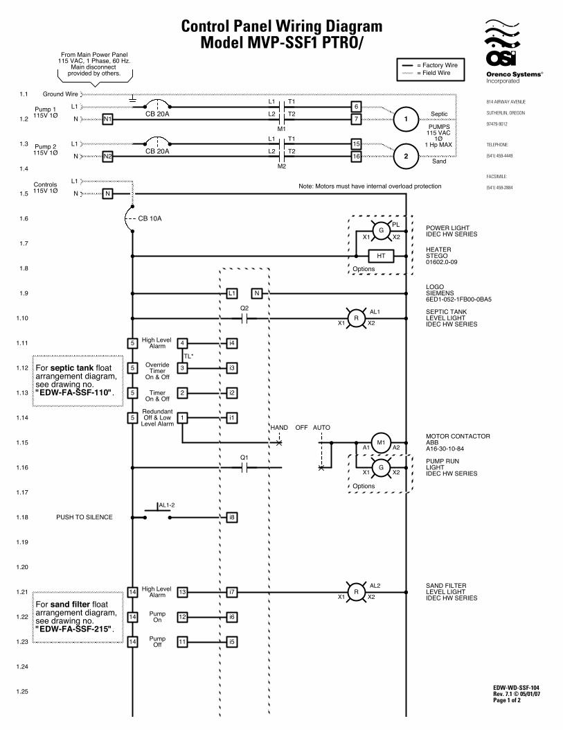
2. Panel Wiring Diagram EDW-WD-SSF-104
3. Float Arrangement Diagram EDW-FA-SSF-110
4. Float Arrangement Diagram EDW-FA-SSF-215
5. MVP-SSF PTRO/ Operation EIN-CP-OP-68
6. MVP-SSF PTRO/ Setting Instructions EIN-CP-SET-60
7. MVP-Time & Date Setting Instructions EIN-CP-SET-111
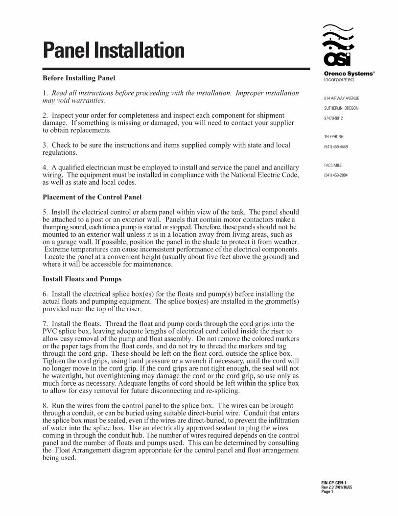
Panel Installation
EIN-CP-GEN-1Rev 2.0 ©01/10/05Page 1
Before Installing Panel
1. Read all instructions before proceeding with the installation. Improper installationmay void warranties.
2. Inspect your order for completeness and inspect each component for shipmentdamage. If something is missing or damaged, you will need to contact your supplierto obtain replacements.
3. Check to be sure the instructions and items supplied comply with state and localregulations.
4. A qualified electrician must be employed to install and service the panel and ancillarywiring. The equipment must be installed in compliance with the National Electric Code,as well as state and local codes.
Placement of the Control Panel
5. Install the electrical control or alarm panel within view of the tank. The panel shouldbe attached to a post or an exterior wall. Panels that contain motor contactors make athumping sound, each time a pump is started or stopped. Therefore, these panels should not bemounted to an exterior wall unless it is in a location away from living areas, such ason a garage wall. If possible, position the panel in the shade to protect it from weather. Extreme temperatures can cause inconsistent performance of the electrical components. Locate the panel at a convenient height (usually about five feet above the ground) andwhere it will be accessible for maintenance.
Install Floats and Pumps
6. Install the electrical splice box(es) for the floats and pump(s) before installing theactual floats and pumping equipment. The splice box(es) are installed in the grommet(s)provided near the top of the riser.
7. Install the floats. Thread the float and pump cords through the cord grips into thePVC splice box, leaving adequate lengths of electrical cord coiled inside the riser toallow easy removal of the pump and float assembly. Do not remove the colored markersor the paper tags from the float cords, and do not try to thread the markers and tagthrough the cord grip. These should be left on the float cord, outside the splice box.Tighten the cord grips, using hand pressure or a wrench if necessary, until the cord willno longer move in the cord grip. If the cord grips are not tight enough, the seal will notbe watertight, but overtightening may damage the cord or the cord grip, so use only asmuch force as necessary. Adequate lengths of cord should be left within the splice boxto allow for easy removal for future disconnecting and re-splicing.
8. Run the wires from the control panel to the splice box. The wires can be broughtthrough a conduit, or can be buried using suitable direct-burial wire. Conduit that entersthe splice box must be sealed, even if the wires are direct-buried, to prevent the infiltrationof water into the splice box. Use an electrically approved sealant to plug the wirescoming in through the conduit hub. The number of wires required depends on the controlpanel and the number of floats and pumps used. This can be determined by consultingthe Float Arrangement diagram appropriate for the control panel and float arrangementbeing used.
Wire should be sized at 14 AWG for the floats. Refer to Figure 1 to determine theproper size for the pump wires. When calculating wire size, the length and size of thebranch circuit wires from the service entrance panel to the pump control panel mustalso be taken into account. Wire that’s too small can cause an excessive voltage dropand poor pump performance.
Wires should be color coded or otherwise marked to aid in wiring the control panel.Drawing EIN-SB-SB-1 lists recommended colors for each of the wires. Colors mayrefer to either the color of the wire’s insulation, the color of a tag, or the color of anelectrical tape marker.
9. All splices made in the splice box should use waterproof wire nuts or butt connectorsand heat shrink tubing. The splices must be waterproof! Splices that are not waterproofmay cause a malfunction of the pump controls if water should leak into the splice box.Refer to Drawing EIN-SB-SB-1 for instructions on making waterproof splices. Referto the appropriate Float Arrangement diagram for instructions on how to connect thefloats together.
Connect Control Panel
10. Connect the wires coming from floats to the terminals in the control panel. Referto the appropriate Float Arrangement diagram for the correct terminal connections.
11. Connect the wires coming from the pump(s) to the pump terminals. Refer to thepanel wiring diagram for the correct terminal connections.
12. Connect the incoming power to the panel. Power to the panel must be appropriateto the control panel and pump motor (i.e. 120VAC, single phase for a 120 VAC motor,240 VAC single phase for a 240 VAC motor, etc.) Insure that the panel is properlygrounded and that the fuse or breaker and wire size, from the main power panel and tothe pump, are sized correctly. Separate circuits for the pump controls and each of thepump motors is recommended. Note: Voltage for the controls in the panel is always120VAC, although the pump voltage may be 120VAC or 240 VAC.
13. Use 60° minimum CU conductors only. Torque the terminal blocks to 15 LB-INand the ground lugs to 45 LB-IN. Torque the circuit breakers to 20 LB-IN for 14-10AWG wire, 25 LB-IN for 8 AWG wire, and 27 LB-IN for 6-4 AWG wire.
14. When power is applied to the control panel, the wires to the pump may be energized.Do not service the pump or any electrical wiring in the pump vault without disconnectingthe power at the circuit breaker and the fuse. The pump vault area is a hazardous area,and may contain explosive gases. Take appropriate precautions before working in thepump vault.
15. If you have any questions please contact Orenco Systems, Inc.
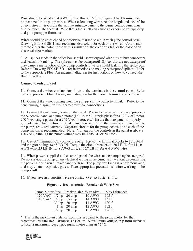
Figure 1. Recommended Breaker & Wire Size
Pump Motor Size Breaker size Wire Size Max Distance*120 VAC 1/2 hp 20 amp 10 AWG 105 ft240 VAC 1/2 hp 15 amp 14 AWG 161 ft
3/4 hp 20 amp 14 AWG 130 ft 1 hp 20 amp 12 AWG 172 ft
1 1/2 hp 20 amp 12 AWG 126 ft
* This is the maximum distance from this subpanel to the pump motor for therecommended wire size. Distance is based on 3% maximum voltage drop from subpanelto load at maximum recognized pump motor amps at 75° C.
EIN-CP-GEN-1Rev 2.0 ©01/10/05Page 2
N
EDW-WD-SSF-104Rev. 7.1 © 05/01/07Page 1 of 2
From Main Power Panel115 VAC, 1 Phase, 60 Hz.
Main disconnect provided by others.
Control Panel Wiring DiagramModel MVP-SSF1 PTRO/
NCB 20A
PUMPS115 VAC
1Ø1 Hp MAX
CB 20AN2
N1Pump 1115V 1Ø
Pump 2115V 1Ø
N
Ground Wire
L1
1
High Level Alarm
TimerOn & Off
RedundantOff & Low
Level Alarm
G
OFFHAND AUTO
1.1
1.2
1.3
1.4
1.5
1.6
1.7
1.8
1.9
1.10
1.11
1.12
1.13
1.14
1.15
1.16
1.17
1.18
1.19
LOGOSIEMENS6ED1-052-1FB00-0BA5
SEPTIC TANKLEVEL LIGHTIDEC HW SERIES
MOTOR CONTACTORABBA16-30-10-84
PUMP RUN LIGHTIDEC HW SERIES
1.20
1.21
1.22
1.23
1.24
1.25
M1
T2L2
T1L1
Options
215
16M2
T2L2
T1L1
= Factory Wire= Field Wire
6
7
5
5
4
2
1
M1A2A1
X2X1
RX2X1
CB 10A
N
L1 N
Q2
i45
i2
i1
Q1
High Level Alarm
PumpOn
PumpOff
14
14
13
12
11
i714
i6
i8PUSH TO SILENCE
SAND FILTERLEVEL LIGHTIDEC HW SERIES
RX2X1
Septic
Sand
Options
HEATERSTEGO01602.0-09
HT
OverrideTimer
On & Off3 i35
i5
TL*
L1
L1Controls115V 1Ø
POWER LIGHTIDEC HW SERIES
PL
X2X1G
For sand filter float arrangement diagram, see drawing no. "EDW-FA-SSF-215".
For septic tank floatarrangement diagram,see drawing no."EDW-FA-SSF-110".
Note: Motors must have internal overload protection
AL1-2
AL1
AL2
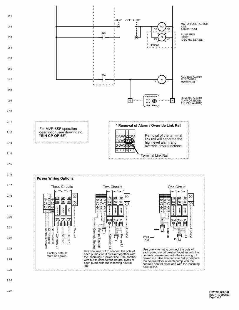
EDW-WD-SSF-104Rev. 7.1 © 05/01/07Page 2 of 2
STP Neutral
Factory default.Wire as shown.
TTThhhrrreeeeee CCCiiirrrcccuuuiiitttsss
ON
20
PUMP
ON
10
CONTRO
LS
SFP Neutral
Ground
N1
ON
20
PUMP
SFP L1
N2
Controls Neutral
STP L1
Controls L1
N
ON
20
PUMP
ON
10
CONTRO
LS
TTTwwwooo CCCiiirrrcccuuuiiitttsss OOOnnneee CCCiiirrrcccuuuiiittt
Neutral
Ground
N1
ON
20
PUMP
L1
N2
ON
20
PUMP
ON
10
CONTRO
LS
Ground
N1
ON
20
PUMP
Pumps L1
N2
WireNut
Controls Neutral
Controls L1
Pumps Neutral
N N
Use one wire nut to connect the pole of each pump circuit breaker together with the incoming L1 power line. Use another wire nut to connect the neutral block of each pump with the incoming neutral line.
Use one wire nut to connect the pole of each pump circuit breaker together with the controls breaker and with the incoming L1 power line. Use another wire nut to connect the neutral block of each pump with the controls neutral block and with the incoming neutral line.
Power Wiring Options
AUDIBLE ALARM FLOYD BELL MW09201Q
REMOTE ALARM(AHW OR EQUIV. 115 VAC ALARM)
2.1
2.2
2.3
2.4
2.5
2.6
2.7
2.8
2.9
2.10
2.11
2.12
2.13
2.14
2.15
2.16
2.17
2.18
2.19
2.20
2.21
2.22
2.23
2.24
2.25
2.26
2.27
A-+
Light Alarm
Remote Alarm
0 N
G
OFFHAND AUTOMOTOR CONTACTORABBA16-30-10-84
PUMP RUN LIGHTIDEC HW SERIES
Options
M2A2A1
X2X1
Q3
Q4
Removal of the terminal link rail will separate the high level alarm and override timer functions.
* Removal of Alarm / Override Link Rail
543210
Terminal Link Rail
For MVP-SSF operationdescription, see drawing no."EIN-CP-OP-68".
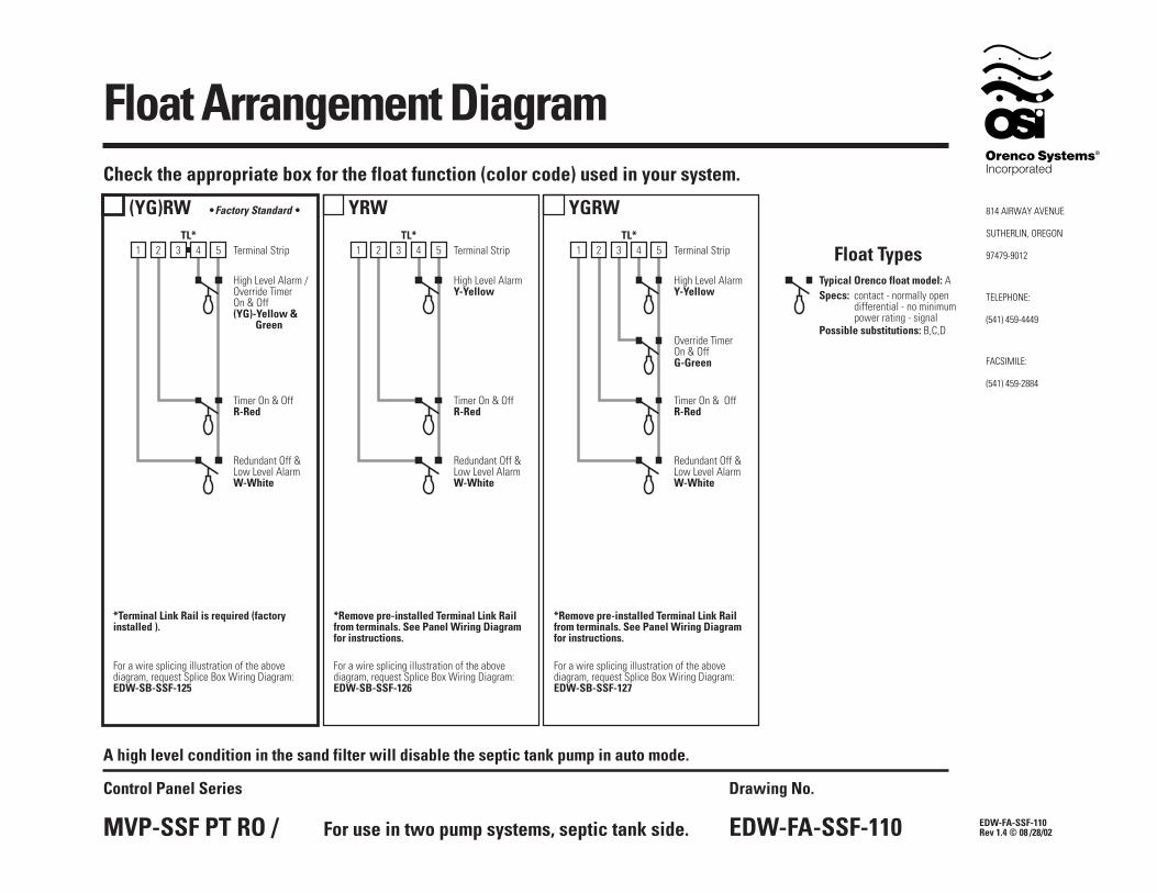
Float Arrangement Diagram
EDW-FA-SSF-110Rev 1.4 © 08 /28/02
Drawing No.
EDW-FA-SSF-110
Control Panel Series
MVP-SSF PT RO /
Check the appropriate box for the float function (color code) used in your system.
Terminal Strip
High Level AlarmY-Yellow
Override TimerOn & OffG-Green
Timer On & OffR-Red
TL*
Redundant Off &Low Level AlarmW-White
*Remove pre-installed Terminal Link Railfrom terminals. See Panel Wiring Diagramfor instructions.
For a wire splicing illustration of the abovediagram, request Splice Box Wiring Diagram:EDW-SB-SSF-127
(YG)RW
Terminal Strip
High Level Alarm /Override TimerOn & Off(YG)-Yellow &
Green
Timer On & OffR-Red
TL*
Redundant Off &Low Level AlarmW-White
*Terminal Link Rail is required (factoryinstalled ).
Terminal Strip
High Level AlarmY-Yellow
Timer On & OffR-Red
TL*
Redundant Off &Low Level AlarmW-White
*Remove pre-installed Terminal Link Railfrom terminals. See Panel Wiring Diagramfor instructions.
For a wire splicing illustration of the abovediagram, request Splice Box Wiring Diagram:EDW-SB-SSF-125
For a wire splicing illustration of the abovediagram, request Splice Box Wiring Diagram:EDW-SB-SSF-126
YRW YGRW•Factory Standard •
For use in two pump systems, septic tank side.
A high level condition in the sand filter will disable the septic tank pump in auto mode.
1 2 53 41 2 53 4 1 2 53 4
Specs: contact - normally opendifferential - no minimumpower rating - signal
Typical Orenco float model: A
Float Types
Possible substitutions: B,C,D
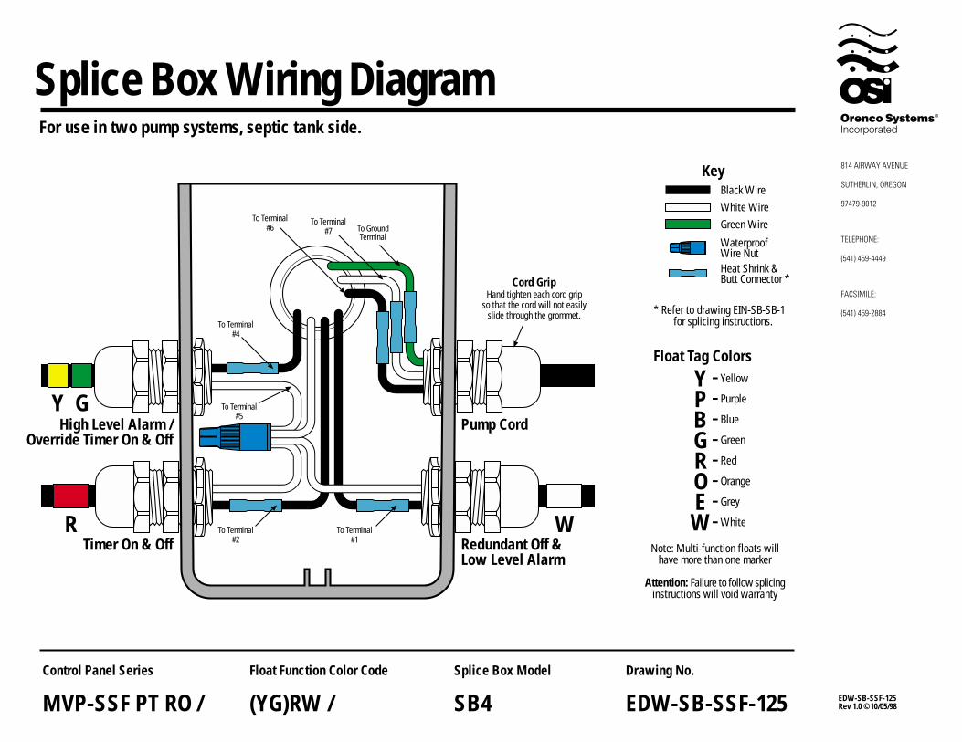
WRTimer On & Off Redundant Off &
Low Level Alarm
High Level Alarm /Override Timer On & Off
Pump CordGY To Terminal
#5
To Terminal#4
To GroundTerminal
To Terminal#7
To Terminal#6
To Terminal#2
To Terminal#1
Splice Box Wiring Diagram
Cord GripHand tighten each cord grip
so that the cord will not easilyslide through the grommet.
YPBGROEW
Yellow
Purple
Blue
Green
Red
Orange
Grey
White
KeyBlack Wire
Green WireWhite Wire
Heat Shrink &Butt Connector *
WaterproofWire Nut
Attention: Failure to follow splicinginstructions will void warranty
Note: Multi-function floats willhave more than one marker
--------
Float Tag Colors
For use in two pump systems, septic tank side.
EDW-SB-SSF-125Rev 1.0 ©10/05/98
Drawing No.
EDW-SB-SSF-125
Float Function Color Code
(YG)RW /
Splice Box Model
SB4
Control Panel Series
MVP-SSF PT RO /
* Refer to drawing EIN-SB-SB-1 for splicing instructions.
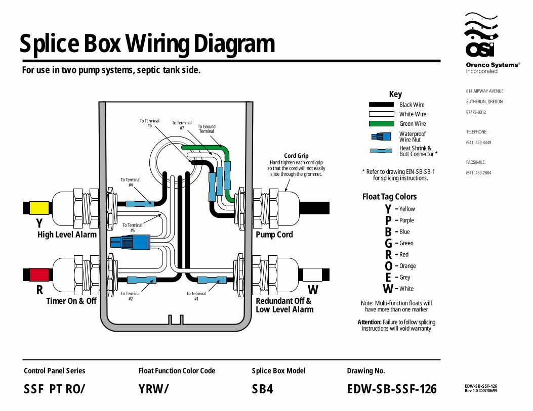
WRTimer On & Off Redundant Off &
Low Level Alarm
YHigh Level Alarm Pump Cord
To Terminal#5
To Terminal#4
To GroundTerminal
To Terminal#7
To Terminal#6
To Terminal#2
To Terminal#1
Splice Box Wiring Diagram
Cord GripHand tighten each cord grip
so that the cord will not easilyslide through the grommet.
YPBGROEW
Yellow
Purple
Blue
Green
Red
Orange
Grey
White
KeyBlack Wire
Green WireWhite Wire
Heat Shrink &Butt Connector *
WaterproofWire Nut
Attention: Failure to follow splicinginstructions will void warranty
Note: Multi-function floats willhave more than one marker
--------
Float Tag Colors
For use in two pump systems, septic tank side.
EDW-SB-SSF-126Rev 1.0 ©07/06/99
Drawing No.
EDW-SB-SSF-126
Float Function Color Code
YRW/
Splice Box Model
SB4
Control Panel Series
SSF PT RO/
* Refer to drawing EIN-SB-SB-1 for splicing instructions.
WRTimer On & Off Redundant Off &
Low Level Alarm
G
Y
Override Timer On & Off
High Level Alarm
Pump Cord
To GroundTerminal
To Terminal#7
To Terminal#6
To Terminal#4
To Terminal#3
To Terminal#2
To Terminal#1
To Terminal#5
Splice Box Wiring Diagram
Cord GripHand tighten each cord grip
so that the cord will not easilyslide through the grommet.
YPBGROEW
Yellow
Purple
Blue
Green
Red
Orange
Grey
White
KeyBlack Wire
Green WireWhite Wire
Heat Shrink &Butt Connector *
WaterproofWire Nut
Attention: Failure to follow splicinginstructions will void warranty
Note: Multi-function floats willhave more than one marker
--------
Float Tag Colors
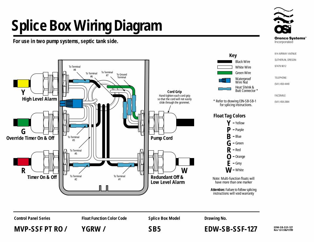
For use in two pump systems, septic tank side.
EDW-SB-SSF-127Rev 1.0 ©06/17/99
Drawing No.
EDW-SB-SSF-127
Float Function Color Code
YGRW /
Splice Box Model
SB5
Control Panel Series
MVP-SSF PT RO /
* Refer to drawing EIN-SB-SB-1 for splicing instructions.
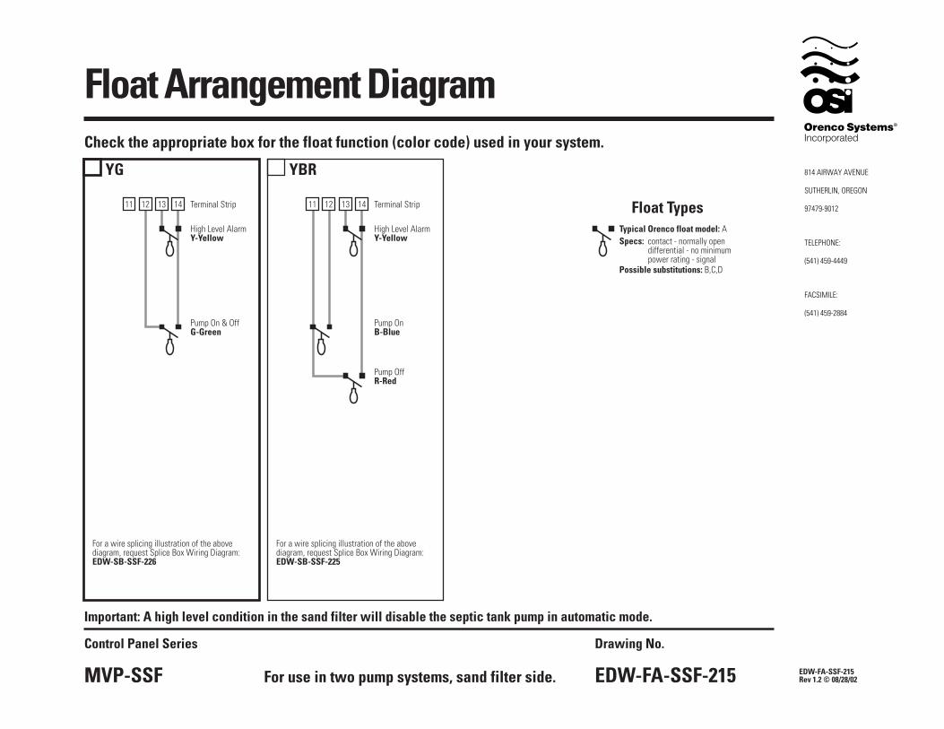
Float Arrangement Diagram
EDW-FA-SSF-215Rev 1.2 © 08/28/02
Drawing No.
EDW-FA-SSF-215
Control Panel Series
MVP-SSF
YG
Terminal Strip
High Level AlarmY-Yellow
Pump On & OffG-Green
For a wire splicing illustration of the abovediagram, request Splice Box Wiring Diagram:EDW-SB-SSF-226
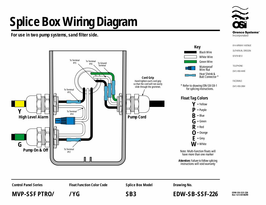
For use in two pump systems, sand filter side.
Important: A high level condition in the sand filter will disable the septic tank pump in automatic mode.
YBR
Terminal Strip
High Level AlarmY-Yellow
Pump OnB-Blue
Pump OffR-Red
For a wire splicing illustration of the abovediagram, request Splice Box Wiring Diagram:EDW-SB-SSF-225
Check the appropriate box for the float function (color code) used in your system.
12 1413 11 12 141311
Specs: contact - normally opendifferential - no minimumpower rating - signal
Typical Orenco float model: A
Float Types
Possible substitutions: B,C,D
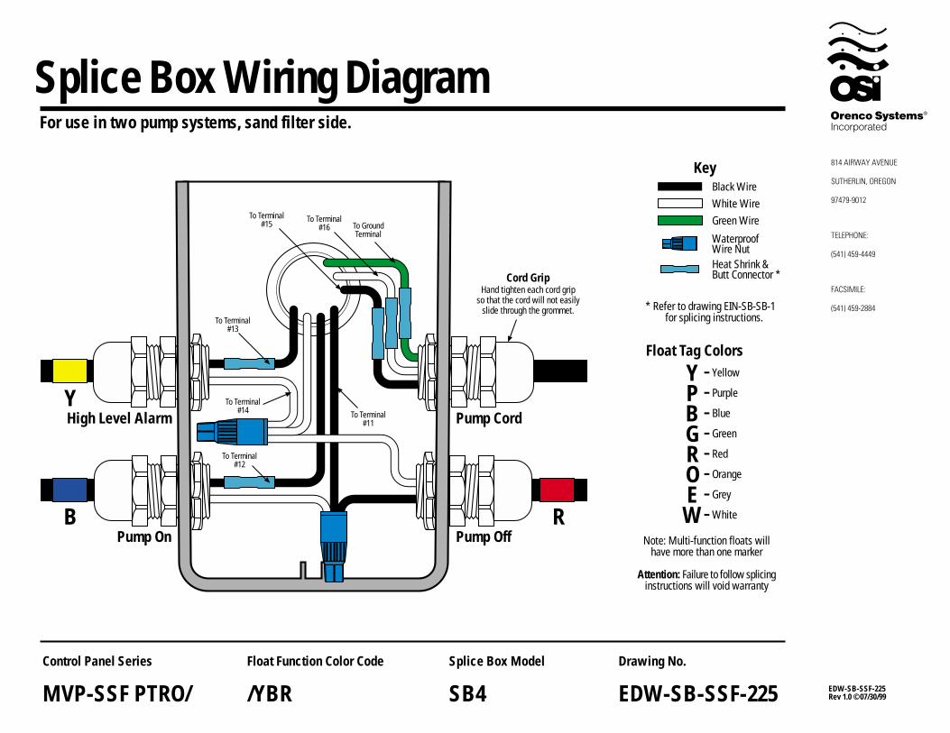
RBPump On Pump Off
YHigh Level Alarm Pump Cord
To Terminal#12
To Terminal#14
To Terminal#13
To GroundTerminal
To Terminal#16
To Terminal#15
Splice Box Wiring Diagram
Cord GripHand tighten each cord grip
so that the cord will not easilyslide through the grommet.
YPBGROEW
Yellow
Purple
Blue
Green
Red
Orange
Grey
White
KeyBlack Wire
Green WireWhite Wire
Heat Shrink &Butt Connector *
WaterproofWire Nut
Attention: Failure to follow splicinginstructions will void warranty
Note: Multi-function floats willhave more than one marker
--------
Float Tag Colors
EDW-SB-SSF-225Rev 1.0 ©07/30/99
Drawing No.
EDW-SB-SSF-225
Float Function Color Code
/YBR
Splice Box Model
SB4
Control Panel Series
MVP-SSF PTRO/
* Refer to drawing EIN-SB-SB-1 for splicing instructions.
For use in two pump systems, sand filter side.
To Terminal#11
GPump On & Off
YHigh Level Alarm Pump Cord
To Terminal#12
To Terminal#14
To Terminal#13
To GroundTerminal
To Terminal#16
To Terminal#15
Splice Box Wiring Diagram
Cord GripHand tighten each cord grip
so that the cord will not easilyslide through the grommet.
YPBGROEW
Yellow
Purple
Blue
Green
Red
Orange
Grey
White
KeyBlack Wire
Green WireWhite Wire
Heat Shrink &Butt Connector *
WaterproofWire Nut
Attention: Failure to follow splicinginstructions will void warranty
Note: Multi-function floats willhave more than one marker
--------
Float Tag Colors
For use in two pump systems, sand filter side.
EDW-SB-SSF-226Rev 1.0 ©07/30/99
Drawing No.
EDW-SB-SSF-226
Float Function Color Code
/ YG
Splice Box Model
SB3
Control Panel Series
MVP-SSF PTRO/
* Refer to drawing EIN-SB-SB-1 for splicing instructions.
MVP-SSF PTRO/ Operation
EIN-CP-OP-68Rev 6.0 © 08/10/05Page 1 of 2
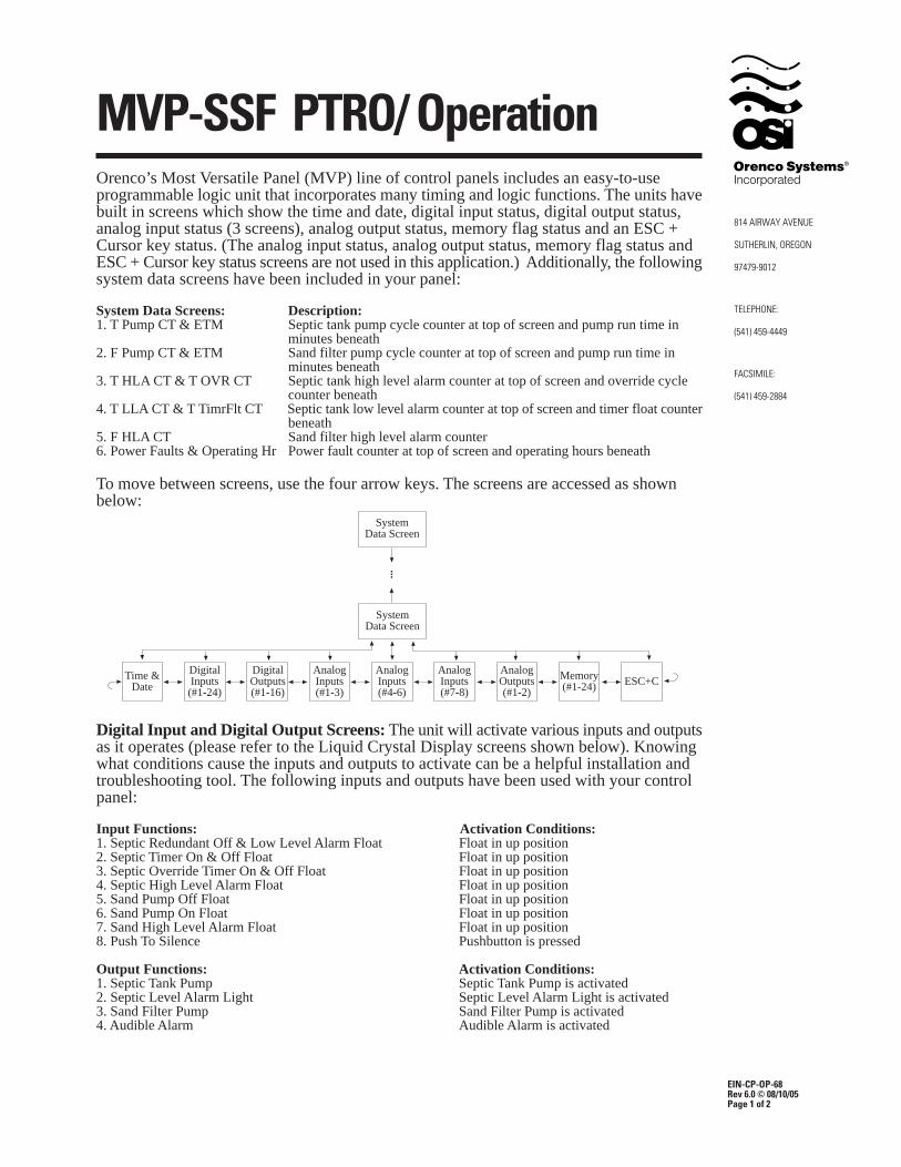
Orenco’s Most Versatile Panel (MVP) line of control panels includes an easy-to-useprogrammable logic unit that incorporates many timing and logic functions. The units havebuilt in screens which show the time and date, digital input status, digital output status,analog input status (3 screens), analog output status, memory flag status and an ESC +Cursor key status. (The analog input status, analog output status, memory flag status andESC + Cursor key status screens are not used in this application.) Additionally, the followingsystem data screens have been included in your panel:
System Data Screens: Description:1. T Pump CT & ETM Septic tank pump cycle counter at top of screen and pump run time in
minutes beneath2. F Pump CT & ETM Sand filter pump cycle counter at top of screen and pump run time in
minutes beneath3. T HLA CT & T OVR CT Septic tank high level alarm counter at top of screen and override cycle
counter beneath4. T LLA CT & T TimrFlt CT Septic tank low level alarm counter at top of screen and timer float counter
beneath5. F HLA CT Sand filter high level alarm counter6. Power Faults & Operating Hr Power fault counter at top of screen and operating hours beneath
To move between screens, use the four arrow keys. The screens are accessed as shownbelow:
Memory(#1-24) ESC+C
AnalogOutputs(#1-2)
SystemData Screen
SystemData Screen
...
AnalogInputs(#4-6)
AnalogInputs(#7-8)
AnalogInputs(#1-3)
DigitalOutputs(#1-16)
Time &Date
DigitalInputs(#1-24)
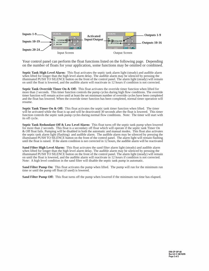
Digital Input and Digital Output Screens: The unit will activate various inputs and outputsas it operates (please refer to the Liquid Crystal Display screens shown below). Knowingwhat conditions cause the inputs and outputs to activate can be a helpful installation andtroubleshooting tool. The following inputs and outputs have been used with your controlpanel:
Input Functions: Activation Conditions:1. Septic Redundant Off & Low Level Alarm Float Float in up position2. Septic Timer On & Off Float Float in up position3. Septic Override Timer On & Off Float Float in up position4. Septic High Level Alarm Float Float in up position5. Sand Pump Off Float Float in up position6. Sand Pump On Float Float in up position7. Sand High Level Alarm Float Float in up position8. Push To Silence Pushbutton is pressed
Output Functions: Activation Conditions:1. Septic Tank Pump Septic Tank Pump is activated2. Septic Level Alarm Light Septic Level Alarm Light is activated3. Sand Filter Pump Sand Filter Pump is activated4. Audible Alarm Audible Alarm is activated
EIN-CP-OP-68Rev 6.0 © 08/10/05Page 2 of 2
Output Screen
Outputs 1-9
Input Screen
Outputs 10-16
Inputs 1-9
Inputs 10-19
Inputs 20-24
ActivatedInput/Output
Your control panel can perform the float functions listed on the following page. Dependingon the number of floats for your application, some functions may be omitted or combined.
Septic Tank High Level Alarm: This float activates the septic tank alarm light (steady) and audible alarmwhen lifted for longer than the high level alarm delay. The audible alarm may be silenced by pressing theilluminated PUSH TO SILENCE button on the front of the control panel. The alarm light (steady) will remainon until the float is lowered, and the audible alarm will reactivate in 12 hours if condition is not corrected.
Septic Tank Override Timer On & Off: This float activates the override timer function when lifted formore than 2 seconds. This timer function controls the pump cycles during high flow conditions. The overridetimer function will remain active until at least the set minimum number of override cycles have been completedand the float has lowered. When the override timer function has been completed, normal timer operation willresume.
Septic Tank Timer On & Off: This float activates the septic tank timer function when lifted. The timerwill be activated while the float is up and will be deactivated 30 seconds after the float is lowered. This timerfunction controls the septic tank pump cycles during normal flow conditions. Note: The timer will start withits off cycle.
Septic Tank Redundant Off & Low Level Alarm: This float turns off the septic tank pump when loweredfor more than 2 seconds. This float is a secondary off float which will operate if the septic tank Timer On& Off float fails. Pumping will be disabled in both the automatic and manual modes. This float also activatesthe septic tank alarm light (flashing) and audible alarm. The audible alarm may be silenced by pressing theilluminated PUSH TO SILENCE button on the front of the control panel. The alarm light will remain flashinguntil the float is raised. If the alarm condition is not corrected in 12 hours, the audible alarm will be reactivated
Sand Filter High Level Alarm: This float activates the sand filter alarm light (steady) and audible alarmwhen lifted for longer than the high level alarm delay. The audible alarm may be silenced by pressing theilluminated PUSH TO SILENCE button on the front of the control panel. The alarm light (steady) will remainon until the float is lowered, and the audible alarm will reactivate in 12 hours if condition is not corrected.Note: A high level condition in the sand filter will disable the septic tank pump in automatic.
Sand Filter Pump On: This float activates the pump when lifted. The pump will run for the minimum runtime or until the pump off float (if used) is lowered.
Sand Filter Pump Off: This float turns off the pump when lowered if the minimum run time has elapsed.
EIN-CP-SET-60Rev 6.0 © 08/10/05Page 1 of 3
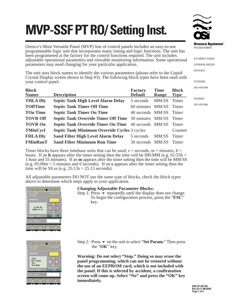
Changing Adjustable Parameter Blocks:Step 1: Press � repeatedly until the display does not change.
To begin the configuration process, press the “ESC” key.
Step 2: Press � on the unit to select “Set Param.” Then press the “OK” key.
Warning: Do not select “Stop.” Doing so may erase thepanel programming, which can not be restored withoutthe use of an EEPROM card, which is not included withthe panel. If this is selected by accident, a confirmationscreen will come up. Select “No” and press the “OK” keyimmediately.
Orenco’s Most Versatile Panel (MVP) line of control panels includes an easy-to-useprogrammable logic unit that incorporates many timing and logic functions. The unit hasbeen programmed at the factory for the control functions required. The unit includesadjustable operational parameters and viewable monitoring information. Some operationalparameters may need changing for your particular application.
The unit uses block names to identify the various parameters (please refer to the LiquidCrystal Display screen shown in Step #3). The following block types have been used withyour control panel:
Block Factory Time BlockNames Description Default Range Type .THLA Dly Septic Tank High Level Alarm Delay 5 seconds MM:SS TimerTOffTime Septic Tank Timer Off Time 60 minutes MM:SS TimerTOn Time Septic Tank Timer On Time 40 seconds MM:SS TimerTOVR Off Septic Tank Override Timer Off Time 30 minutes MM:SS TimerTOVR On Septic Tank Override Timer On Time 40 seconds MM:SS TimerTMinCycl Septic Tank Minimum Override Cycles 3 cycles CounterFHLA Dly Sand Filter High Level Alarm Delay 5 seconds MM:SS TimerFMinRunT Sand Filter Minimum Run Time 30 seconds MM:SS Timer
Timer blocks have three timebase units that can be used; s = seconds, m = minutes, h =hours. If an h appears after the timer setting then the time will be HH:MM (e.g. 01:55h =1 hour and 55 minutes). If an m appears after the timer setting then the time will be MM:SS(e.g. 05:00m = 5 minutes and 0 seconds). If an s appears after the timer setting then thetime will be SS.ss (e.g. 25:13s = 25.13 seconds).
All adjustable parameters DO NOT use the same type of blocks, check the block typesabove to determine which steps apply to your application.
MVP-SSF PT RO/ Setting Inst.
EIN-CP-SET-60Rev 6.0 © 08/10/05Page 2 of 3
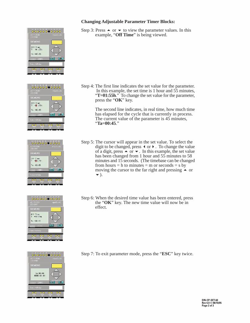
Changing Adjustable Parameter Timer Blocks:
Step 3: Press � or � to view the parameter values. In this example, “Off Time” is being viewed.
Step 4: The first line indicates the set value for the parameter. In this example, the set time is 1 hour and 55 minutes,“T=01:55h.” To change the set value for the parameter,press the “OK” key.
The second line indicates, in real time, how much timehas elapsed for the cycle that is currently in process.The current value of the parameter is 45 minutes, “Ta=00:45.”
Step 5: The cursor will appear in the set value. To select thedigit to be changed, press �or�. To change the valueof a digit, press � or �. In this example, the set valuehas been changed from 1 hour and 55 minutes to 58 minutes and 15 seconds. (The timebase can be changedfrom hours = h to minutes = m or seconds = s bymoving the cursor to the far right and pressing � or�).
Step 6: When the desired time value has been entered, press the “OK” key. The new time value will now be in effect.
Step 7: To exit parameter mode, press the “ESC” key twice.
EIN-CP-SET-60Rev 6.0 © 08/10/05Page 3 of 3
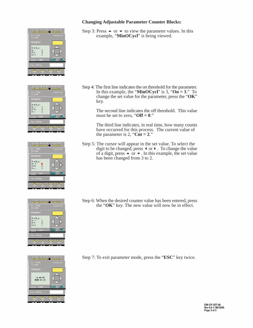
Changing Adjustable Parameter Counter Blocks:
Step 3: Press � or � to view the parameter values. In this example, “MinOCycl” is being viewed.
Step 4: The first line indicates the on threshold for the parameter.In this example, the “MinOCycl” is 3, “On = 3.” Tochange the set value for the parameter, press the “OK”key.
The second line indicates the off threshold. This valuemust be set to zero, “Off = 0.”
The third line indicates, in real time, how many countshave occurred for this process. The current value of the parameter is 2, “Cnt = 2.”
Step 5: The cursor will appear in the set value. To select thedigit to be changed, press �or�. To change the valueof a digit, press � or �. In this example, the set valuehas been changed from 3 to 2.
Step 6: When the desired counter value has been entered, pressthe “OK” key. The new value will now be in effect.
Step 7: To exit parameter mode, press the “ESC” key twice.
MVP - Control Panel InstructionsContrast Adjustment and Time & Date Settings
EIN-CP-SET-111Rev 7.0 © 08/09/05Page 1 of 2
Orenco’s Most Versatile Panel (MVP) line of control panels includes an easy-to-useprogrammable logic unit that incorporates many timing and logic functions. The readabilityof the display may vary with temperature and ambient light. If the screen is difficult to read,adjusting the contrast is recommended. Instructions for adjusting the contrast are shownbelow. Setting the date and time is typically not necessary. However, if required, the timeand date can be set by following instructions shown below.
To adjust the settings, use the four arrow keys located on the face of the unit (up, down, left,and right), along with the “ESC” key and the “OK” key. Follow the steps, below:
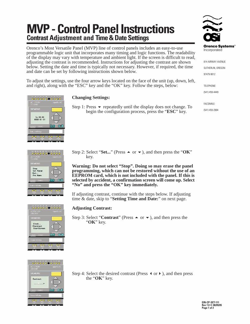
Changing Settings:
Step 1: Press � repeatedly until the display does not change. To begin the configuration process, press the “ESC” key.
Step 2: Select “Set...” (Press � or �), and then press the “OK” key.
Warning: Do not select “Stop”. Doing so may erase the panelprogramming, which can not be restored without the use of anEEPROM card, which is not included with the panel. If this isselected by accident, a confirmation screen will come up. Select“No” and press the “OK” key immediately.
If adjusting contrast, continue with the steps below. If adjustingtime & date, skip to “Setting Time and Date:” on next page.
Adjusting Contrast:
Step 3: Select “Contrast” (Press � or �), and then press the “OK” key.
Step 4: Select the desired contrast (Press �or�), and then press the “OK” key.
EIN-CP-SET-111Rev 7.0 © 08/09/04Page 2 of 2
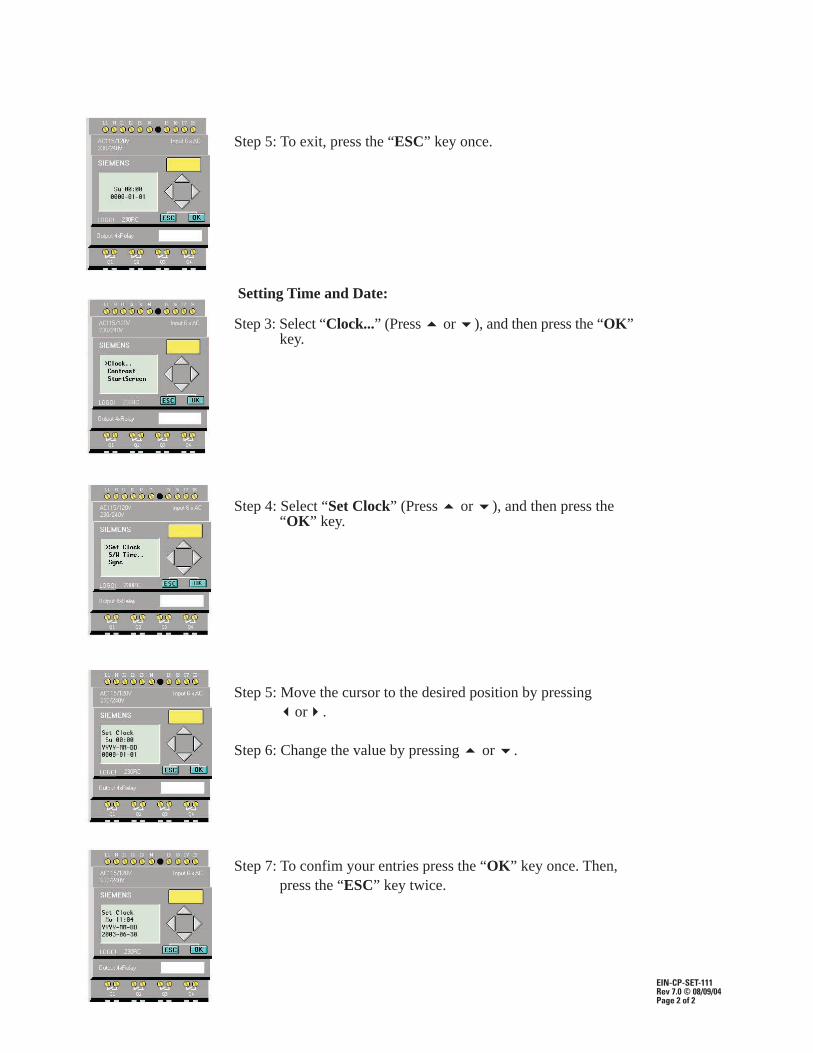
Step 5: To exit, press the “ESC” key once.
Setting Time and Date:
Step 3: Select “Clock...” (Press � or �), and then press the “OK”key.
Step 4: Select “Set Clock” (Press � or �), and then press the “OK” key.
Step 5: Move the cursor to the desired position by pressing�or�.
Step 6: Change the value by pressing � or �.
Step 7: To confim your entries press the “OK” key once. Then, press the “ESC” key twice.
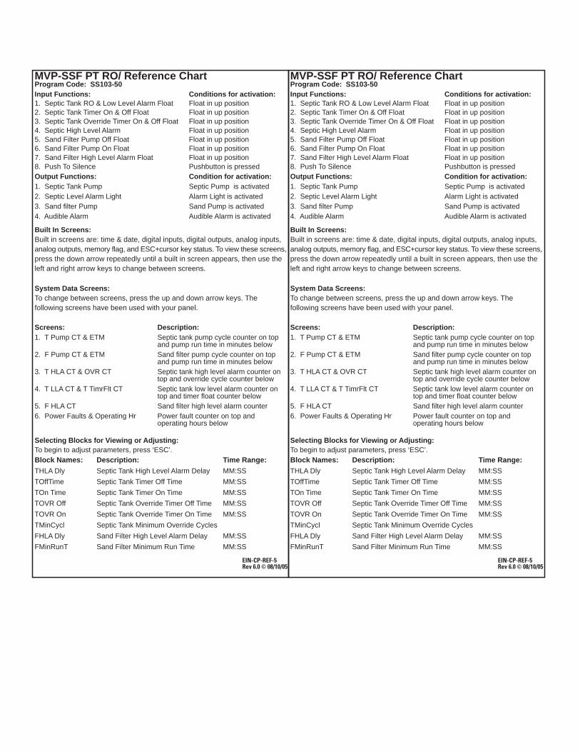
MVP-SSF PT RO/ Reference ChartProgram Code: SS103-50Input Functions: Conditions for activation:1. Septic Tank RO & Low Level Alarm Float Float in up position2. Septic Tank Timer On & Off Float Float in up position3. Septic Tank Override Timer On & Off Float Float in up position4. Septic High Level Alarm Float in up position5. Sand Filter Pump Off Float Float in up position6. Sand Filter Pump On Float Float in up position7. Sand Filter High Level Alarm Float Float in up position8. Push To Silence Pushbutton is pressedOutput Functions: Condition for activation:1. Septic Tank Pump Septic Pump is activated2. Septic Level Alarm Light Alarm Light is activated3. Sand filter Pump Sand Pump is activated4. Audible Alarm Audible Alarm is activated
Built In Screens:Built in screens are: time & date, digital inputs, digital outputs, analog inputs,analog outputs, memory flag, and ESC+cursor key status. To view these screens,press the down arrow repeatedly until a built in screen appears, then use theleft and right arrow keys to change between screens.
System Data Screens:To change between screens, press the up and down arrow keys. Thefollowing screens have been used with your panel.
Screens: Description:1. T Pump CT & ETM Septic tank pump cycle counter on top
and pump run time in minutes below2. F Pump CT & ETM Sand filter pump cycle counter on top
and pump run time in minutes below3. T HLA CT & OVR CT Septic tank high level alarm counter on
top and override cycle counter below4. T LLA CT & T TimrFlt CT Septic tank low level alarm counter on
top and timer float counter below5. F HLA CT Sand filter high level alarm counter6. Power Faults & Operating Hr Power fault counter on top and
operating hours below
Selecting Blocks for Viewing or Adjusting:To begin to adjust parameters, press ‘ESC’.Block Names: Description: Time Range:THLA Dly Septic Tank High Level Alarm Delay MM:SS
TOffTime Septic Tank Timer Off Time MM:SS
TOn Time Septic Tank Timer On Time MM:SS
TOVR Off Septic Tank Override Timer Off Time MM:SS
TOVR On Septic Tank Override Timer On Time MM:SS
TMinCycl Septic Tank Minimum Override Cycles
FHLA Dly Sand Filter High Level Alarm Delay MM:SS
FMinRunT Sand Filter Minimum Run Time MM:SS
EIN-CP-REF-5Rev 6.0 © 08/10/05
EIN-CP-REF-5Rev 6.0 © 08/10/05