Embed Size (px)
Citation preview

WARNING: Improper installation, adjustment, alteration, service or maintenancecan cause injury or property damage. Refer to this manual. For assis-tance or additional information, contact a qualified installer, serviceagency, or the gas supplier.
FOR YOUR SAFETYDo not store or use gasoline or other flammable vapors and liquid inthe vicinity of this or any other appliance.
FOR YOUR SAFETYIf you smell gas:
1. Open windows.2. Don’t touch electrical switches.3. Extinguish any open flame.4. Immediately call your gas supplier.
For N62X and N62XXX models: 6 cu.ft., 2-way, R.V. refrigerators.For N64X and N64XXX models: 6 cu.ft., 2-way or 3-way, R.V. refrigerators.For N64XIM and N64XIMXX models: 6 cu.ft., 2 way, R.V. refrigerators with ice maker.For N82X and N82XXX models: 8 cu.ft., 2-way, R.V. refrigerators.For N84X and N84XXX models: 8 cu.ft., 2-way or 3-way, R.V. refrigerators.For N84XIM and N84XIMXX models: 8 cu.ft., 2-way, R.V. refrigerators with ice maker.
The model numbers of 3-way refrigerators include “.3”. The model numbers of 2-way refrigera-tors do not.
NORCOLD, Inc.P.O. Box 4248Sidney, OH 45365-4248
Part No. 621831J (7-03)
English
French
Installation Manual
WARNING: DO NOT install this refrigerator in below deck marineapplications. Do not install this refrigerator in a fixed indoor cabin orother dwelling applications. This refrigerator must use onlyNORCOLD designed and approved outside air intake and exhaustventilation for correct and safe operation. Any other ventilation couldcause lethal combustion exhaust fumes and/or explosive propanegas fumes to be in the living area and/or to be below deck.
Installation Manual 2
Table of Contents
Safety Awareness
Safety Instructions
Safety Awareness ....................................................................... 2Safety Instructions ...................................................................... 2Certification and Code Requirements ....................................... 3Ventilation Requirements ........................................................... 3Assemble the Enclosure for the Refrigerator ............................ 4Install the Lower and Upper Vents ............................................. 4Install the Decorative Door panels (nonmetal door models) .... 6Install the Refrigerator ................................................................ 6Reverse the Door Swing (optional) ............................................ 7Connect the Ice Maker (N64XIM, N64XIMXX, N84XIM, and
N84XIMXX models) ............................................................. 8Connect the water supply line ............................................. 8
Connect the Electrical Components .......................................... 8Connect the 120 volts AC supply ........................................ 8Connect the 12 volts DC supply .......................................... 9
Connect the Propane Gas Components ................................... 9Connect the propane gas supply system........................... 9Examine the gas supply system for leaks ........................ 10
Ignition and Start Up ................................................................. 10Ignition and start up (N64X, N64XXX, N64XIM, N64XIMXX,
N84X, N84XXX, N84XIM, and N84XIMXX models) .... 10Ignition and start up (N62X, N62XX, N82X, and N82XX
models) ...................................................................... 10Do a test of the gas safety valve ......................................... 11Shut down-all models ........................................................ 11
Fault Codes (N62X, N62XX, N82X, and N82XX models) ........ 12Fault Codes (N64X, N64XXX, N64XIM, N64XIMXX,
N84X, N84XXX, N84XIM, and N84XIMXX models) .... 13
Read this manual carefully and understand the contents beforeyou install the refrigerator.
Be aware of possible safety hazards when you see the safetyalert symbol on the refrigerator and in this manual. A signalword follows the safety alert symbol and identifies the danger ofthe hazard. Carefully read the descriptions of these signalwords to fully know their meanings. They are for your safety.
WARNING: This signal word means a hazard, which ifignored, can cause dangerous personal injury, death, ormuch property damage.
CAUTION: This signal word means a hazard, which ifignored, can cause small personal injury or muchproperty damage.
WARNING:
- This refrigerator is not approved for use as a freestanding refrigerator. It is equipped for the use ofpropane gas only and can not be changed to use anyother fuels (natural gas, butane, etc.).
- Incorrect installation, adjustment, alteration, or mainte-nance of this refrigerator can cause personal injury,property damage, or both.
- Obey the instructions in this manual to install intake andexhaust vents.
- Do not install the refrigerator directly on carpet. Put therefrigerator on a metal or wood panel that extends the fullwidth and depth of the refrigerator.
- Propane gas can ignite and cause an explosion that canresult in property damage, personal injury, or death. Donot smoke or create sparks. Do not use an open flameto examine the propane gas supply line for leaks. Alwaysuse two wrenches to tighten or loosen the propane gassupply line connections.
- Make sure the electrical installation obeys all applicablecodes. See “Certification and Code Requirements”section.
- Do not bypass or change the refrigerator’s electricalcomponents or features.
- Do not spray liquids near electrical outlets, connections,or the refrigerator components. Many liquids are electri-cally conductive and can cause a shock hazard, electricalshorts, and in some cases fire.
- The refrigerator cooling system is under pressure. Do nottry to repair or to recharge a defective cooling system.
- The cooling system contains sodium chromate. Thebreathing of certain chromium compounds can causecancer. The cooling system contents can cause severeskin and eye burns, and can ignite and burn with anintense flame. Do not bend, drop, weld, move, drill,puncture, or hit the cooling system.
CAUTION:
- The rear of the refrigerator has sharp edges and corners.To prevent cuts or abrasions when working on therefrigerator, use caution and wear cut resistant gloves.

Installation Manual 3
Certification and Code Requirements Ventilation Requirements
WARNING: The completed installation must:
- Make sure there is sufficient intake of fresh air forcombustion.
- Make sure the living space is completely isolated fromthe combustion system of the refrigerator.
- Make sure there is complete and unrestricted ventila-tion of the flue exhaust which, in gas mode, canproduce carbon monoxide. The breathing of carbonmonoxide fumes can cause dizziness, nausea, or inextreme cases, death.
- Make sure the refrigerator is completely isolated fromits heat generating components through the correctuse of baffles and panel construction.
Certified installation needs one lower intake vent and one upperexhaust vent. Install the vents exactly as written in this manual.Any other installation method voids both the certification and thefactory warranty of the refrigerator.
The bottom of the opening for the lower intake vent, which isalso the service access door, must be even with or immediatelybelow the floor level. This allows any leaking propane gas toescape to the outside and not to collect at floor level.
CSA International certification allows the refrigerator to havezero (0) inch minimum clearance at the sides, rear, top, andbottom. While there are no maximum clearances specified forcertification, the following maximum clearances are necessaryfor correct refrigerator performance:
Bottom 0 inch min. 0 inch max.
Each Side 0 inch min 1/2 inch max.
Top 0 inch min. 1/4 inch max.
Rear 0 inch min. 1 inch max.
These clearances plus the lower and upper vents cause thenatural air draft that is necessary for good refrigeration. Coolerair comes in through the lower vent, goes up around therefrigerator coils where it removes the excess heat from therefrigerator components, and goes out through the upper vent.If this air flow is blocked or decreased, the refrigerator will notcool correctly.
Each NORCOLD model is certified by CSA International forcorrect ventilation. Install only the certified vents that are listedin this manual.
This refrigerator is certified by CSA International as meeting thelatest edition of ANSI Z21.19 / CAN 1.4 standards for installationin mobile homes or recreational vehicles.
The installation must obey these standards and this“Installation Manual” for the NORCOLD limited warranty to be ineffect. Installation must conform with the following asapplicable:
In the United States and Canada:
- Local codes, or in the absence of local codes, the NationalFuel Gas Code, ANSI Z223.1/NFPA 54, the Natural Gas andPropane installation Code, CSA B149.1, ANSI A119.2Recreational Vehicles Code, and CSA Z240 RV Series,Recreational Vehicles.
- A manufactured home (mobile home) installation mustconform with the Manufactured Home Construction andSafety Standard, Title 24 CFR, Part 3280 [formerly theFederal Standard for Mobile Home Construction and Safety,Title 24 (part 280), and the current CSA Z240.4, Gas-equipped Recreational Vehicles and Mobile Housing.
- If an external power source is utilized, the appliance, wheninstalled, must be electrically grounded in accordance withlocal codes or, in the absence of local codes, the NationalElectrical code, and ANSI/NFPA 70, or the CanadianElectrical Code, CSA C22.2. Parts 1 and 2.
All propane gas supply piping and fittings must obey local,state, and national codes about type and size. Thesecomponents must also obey the current NFPA 501C section 2-4, and in Canada with the current CAN 1-6.10 Standard.

Installation Manual 4
Install the Lower and Upper Vents
1. Using the following chart, decide which vents and roughopening (RO) sizes to use:
Certified Vent P/N RO Height RO Width
Upper Roof 622293 N/A N/AExhaust Cap
Upper Roof 616319 24 in. 5 1/4 in.Exhaust Vent
Upper Exhaust 621156 13 3/4 in. 21 1/2 in.& Lower IntakePlastic
Lower Square 616010 9 3/4 in. 19 3/8 in.Corner Intake
2. Install the lower intake vent (See Art01598, Art01599, andArt01602):
NOTE: The lower intake vent is also the service accessopening for the components on the rear of the refrig-erator.
WARNING: Make sure the bottom of the opening of thelower intake vent is even with or immediately below thefloor level. This allows any leaking propane gas toescape to the outside and not to collect at floor level.
- Make sure the bottom of the opening of the lower intake vent[1] is even with or immediately below the floor level.
- Align the lower intake vent vertically below the coils [2] andthe condenser [3] of the refrigerator.
Assemble the Enclosure for the Refrigerator
1. Make sure the enclosure is 59.88 - 60.01 inches high forN82X, N82XXX, N84X, N84XXX, N84XIM, and N84XIMXXmodels or 52.88 - 53.01 inches high for N62X, N62XXX,N64X, N64XXX, N64XIM, and N64XIMXX models x 23.50 -23.63 inches wide x 24.00 inches deep.
2. Make sure the floor is solid and level.
- The floor must be metal or a wood panel and extend the fullwidth and depth of the enclosure.
- The floor must be able to support the weight of the refrigera-tor and its contents.
3. Make sure there are no adjacent heat sources such as afurnace vent, a hot water heater vent, etc.
3. Install the upper exhaust vent:
CAUTION: Make sure that no sawdust, insulation, orother construction debris is on the refrigerator or in theenclosure. Debris can cause a combustion hazard andprevent the refrigerator from operating correctly.
NOTE: Tighten the screws of the upper roof exhaust cap to 10inch-pounds max. Also make sure that the air flowaround the upper roof exhaust cap is not blocked ordecreased by other roof mounted features such as aluggage carrier, an air conditioner, a solar panel, etc.
- If the design of the vehicle allows, install the roof exhaustvent [4] directly above the condenser [3] of the refrigerator(See Art01598):
- Install a baffle [5] to prevent stagnant hot air in the area[6] above the refrigerator.
- Make sure there is less than 1/4 inch clearance [7]between the baffle and the top of the refrigerator.
- Make sure the baffle is the full width of the inside ofthe enclosure.
- If the design of the vehicle does not allow you to install theroof exhaust vent directly above the condenser [3] of therefrigerator (See Art01599):
- Align the roof exhaust vent [4] above the condenser [3]of the refrigerator and move it inboard as necessary.
- Install two baffles [8] to prevent stagnant hot air in thearea [6] above the refrigerator.
- Make sure the baffles are the full width of theinside of the enclosure.
- Make sure that the baffles are no more than 45°from vertical [9].
- Put one baffle between the top rear edge of therefrigerator and the inside edge of the upperexhaust vent opening.
- Put the other baffle between the outside edge ofthe upper exhaust vent opening and the side wallof the vehicle.
- If the depth of the enclosure is 24 inches or more and isless than 25 inches, no baffles are necessary at the rear ofthe enclosure.
- If the depth of the enclosure is 25 inches or more and isless than 26 inches, add two baffles [10] to the rear of theenclosure (See Art01598 and Art01599).

Installation Manual 5
- Put one baffle 18 inches to 18 1/2 inches above thebottom of the enclosure [26] (4 1/4 inches to 4 3/4inches above the top of the lower intake vent openingREF) [27] .
- Put the other baffle at the lowest edge of the condenser[3] of the refrigerator.
- Make sure that the baffles are 1 inch or less [28]from the coils [2] and condenser of the refrigerator.
- Make sure that the baffles are the full width of theinside of the enclosure.
- If the depth of the enclosure is more than 26 inches, installa wood or an aluminum or galvanized sheet solid box baffle[25] in the rear of the enclosure (See Art01617 andArt01618).
- Make sure that the bottom of the solid box baffle is 18inches to 18 1/2 inches above the bottom of theenclosure [26] (4 1/4 inches to 4 3/4 inches above thetop of the lower intake vent opening REF) [27] .
- Make sure that the back of the solid box baffle isperpendicular to the bottom of the enclosure.
- Make sure that the back of the solid box baffle is eitheragainst the top of the enclosure or against the angledbaffle [8] (depending on the vehicle design).
- Make sure that the solid box baffle is one inch orless [28] from the coils [2] and condenser of therefrigerator.
- Make sure that the solid box baffle is the full widthof the inside of the enclosure.
- If there is more than 1/2 inch of clearance between eitherside of the refrigerator and the wall, fill the space withfiberglass insulation or add a baffle to eliminate the excessclearance.
- If the design of the vehicle does not allow you to install aroof exhaust vent, install an upper side-wall exhaust vent.
NOTE: The refrigerator is 23.7 in. min. to 24.0 in. max. fromthe rear of the breaker to the rear of the condenser[11].
N62X, N62XXX, N64X, N64XXX, N64XIM, andN64XIMXX models are 48.7 in. min. to 49.0 in. max.from the bottom of the refrigerator to the bottom ofthe refrigerator condenser [12].
N82X, N82XXX, N84X, N84XXX, N84XIM, andN84XIMXX models are 55.7 in. min. to 56.0 in. max.from the bottom of the refrigerator to the bottom ofthe refrigerator condenser [12] (See Art01601).
CAUTION: Only use an upper side-wall exhaust venton refrigerator models that are equipped with a fan. Ifyou use an upper side-wall exhaust vent on a refrigera-tor model that is not equipped with a fan, the refrigera-tor cooling performance will be poor.
- Make sure the refrigerator model is equipped with afan.
- Install the upper side-wall exhaust vent [13] (SeeArt01592 and Art01593).
- For N62X, N62XXX, N64X, N64XXX, N64XIM, andN64XIMXX models, make sure the distance [14]from the bottom of the enclosure to the top of therough opening for the upper exhaust vent is atleast 55 inches.
- For N82X, N82XXX, N84X, N84XXX, N84XIM, andN84XIMXX models, make sure the distance [14]from the bottom of the enclosure to the top of therough opening for the upper exhaust vent is atleast 62 inches.
- Align the upper exhaust vent [13] horizontally abovethe lower intake vent [1] of the refrigerator.
- To prevent stagnant hot air in the area above therefrigerator, install an aluminum or galvanizedsteel sheet baffle [15] between the top of therefrigerator and the top of the upper exhaust vent.
- Make sure there is less than 1/4 inch clear-ance between the baffle and the top of therefrigerator and that the baffle overlaps therefrigerator 1 inch or less [16].
- Make sure that the baffle is against the wall ofthe vehicle at the top of the upper exhaust ventand 1/4 inch or less from the top of theopening for the upper exhaust vent [17].
- Make sure the baffle is the full width of theinside of the enclosure
- Make sure the clearance at the sides of the refrigerator iscorrect:
- If there is more than 1/2 inch of clearance betweeneither side of the refrigerator and the wall, fill the spacewith fiberglass insulation or add a baffle to eliminatethe excess clearance.

Installation Manual 6
Put the refrigerator in position (See Art00962, Art00963, andArt00964):
WARNING: Make sure the combustion seal [11] is notbroken, is completely around the refrigerator mountingflanges, and is between the mounting flanges and thewall of the enclosure If the seal is not complete, exhaustfumes can be present in the living area of the vehicle.The breathing of exhaust fumes can cause dizziness,nausea, or in extreme cases, death.
- Push the refrigerator completely into the enclosure.
- Put the upper trim piece [13] onto the front of the refrigerator.
- Put screws [12] through the upper and lower mountingflanges on the front of the refrigerator and into the enclo-sure wall and floor.
- Put a cap [14] on each of the screw holes in the upper trimpiece [13] on the front of the refrigerator.
WARNING: Do not omit the bottom trim piece. Thispiece is part of the combustion seal.
Install the Refrigerator
NOTE: The doors are made to accept decorative panels. Thedecorative panels must be 3/16 inch or less inthickness. Install the decorative door panels in therefrigerator doors before installing the refrigerator inthe vehicle.
- Make an upper door panel that is 21 19/32 inches wide x 1417/32 inches high.
- Make a lower door panel that is:
- 21 19/32 inches wide and
- 31 5/8 inches high (for N62X, N64X, and N64XIMmodels) or
- 38 5/8 inches high (for N82X, N84X, and N84XIMmodels).
- Pull the panel retainer [1] off each door (See Art00965).
- Push the decorative door panel [2] into the slots of the door[3].
- Push each panel retainer into the slot on the edge of thedoor.
Install Decorative Door Panels (non-metaldoor models)
- When using an upper side-wall exhaust vent:
- If the depth of the enclosure is more than 24 inchesand less than 26 inches [18], install a bent aluminumor galvanized steel sheet baffle [19] to the rear of theenclosure (See Art01592).
- Make sure that the bend of the baffle is the fullwidth of the inside of the enclosure.
- Make sure that the bend of the baffle is flush withthe bottom edge of the upper intake vent doorframe.
- Make sure that the top edge of the baffle is 1/4inch or less [20] below the condenser [3] and thatthere is 1/4 inch or less clearance [21] betweenthe lower rear corner of the condenser and thebaffle.
- If the depth of the enclosure is more than 26 inches[22], install a wood or an aluminum or galvanized steelsheet solid box baffle [23] between the lower intakevent and the upper exhaust vent (See Art01593).
- Make sure that the solid box baffle is the full widthof the inside of the enclosure.
- Make sure that the bottom of the solid box baffle is18 inches to 18 1/2 inches above the bottom of theenclosure [26] (4 1/4 inches to 4 3/4 inches abovethe top of the lower intake vent opening REF) [27] .
- Make sure that the back of the solid box baffle isperpendicular to the bottom of the enclosure.
- Make sure that the horizontal top of the solid boxbaffle is even with the bottom edge of the upperexhaust vent [13].
- Make sure that the vertical top edge of the baffle is1/4 inch or less [20] below the lower rear corner ofthe condenser [3].
- Make sure that there is 1/4 inch or less clearance[21] between the rear of the condenser and thebaffle.
Installation Manual 7
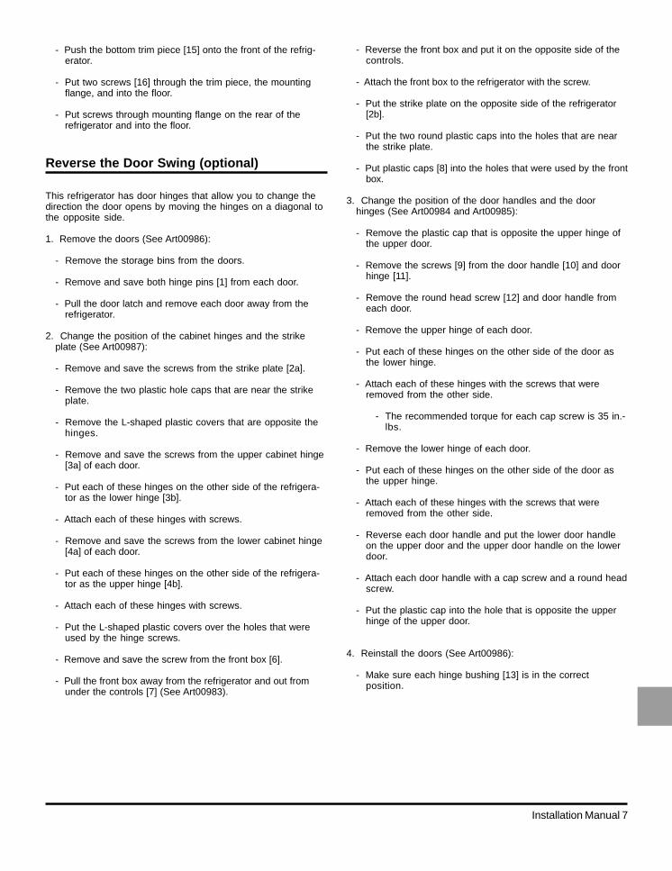
Reverse the Door Swing (optional)
This refrigerator has door hinges that allow you to change thedirection the door opens by moving the hinges on a diagonal tothe opposite side.
1. Remove the doors (See Art00986):
- Remove the storage bins from the doors.
- Remove and save both hinge pins [1] from each door.
- Pull the door latch and remove each door away from therefrigerator.
2. Change the position of the cabinet hinges and the strikeplate (See Art00987):
- Remove and save the screws from the strike plate [2a].
- Remove the two plastic hole caps that are near the strikeplate.
- Remove the L-shaped plastic covers that are opposite thehinges.
- Remove and save the screws from the upper cabinet hinge[3a] of each door.
- Put each of these hinges on the other side of the refrigera-tor as the lower hinge [3b].
- Attach each of these hinges with screws.
- Remove and save the screws from the lower cabinet hinge[4a] of each door.
- Put each of these hinges on the other side of the refrigera-tor as the upper hinge [4b].
- Attach each of these hinges with screws.
- Put the L-shaped plastic covers over the holes that wereused by the hinge screws.
- Remove and save the screw from the front box [6].
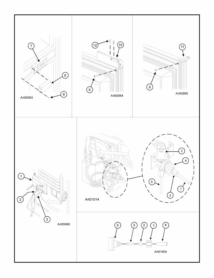
- Pull the front box away from the refrigerator and out fromunder the controls [7] (See Art00983).
- Push the bottom trim piece [15] onto the front of the refrig-erator.
- Put two screws [16] through the trim piece, the mountingflange, and into the floor.
- Put screws through mounting flange on the rear of therefrigerator and into the floor.
- Reverse the front box and put it on the opposite side of thecontrols.
- Attach the front box to the refrigerator with the screw.
- Put the strike plate on the opposite side of the refrigerator[2b].
- Put the two round plastic caps into the holes that are nearthe strike plate.
- Put plastic caps [8] into the holes that were used by the frontbox.
3. Change the position of the door handles and the doorhinges (See Art00984 and Art00985):
- Remove the plastic cap that is opposite the upper hinge ofthe upper door.
- Remove the screws [9] from the door handle [10] and doorhinge [11].
- Remove the round head screw [12] and door handle fromeach door.
- Remove the upper hinge of each door.
- Put each of these hinges on the other side of the door asthe lower hinge.
- Attach each of these hinges with the screws that wereremoved from the other side.
- The recommended torque for each cap screw is 35 in.-lbs.
- Remove the lower hinge of each door.
- Put each of these hinges on the other side of the door asthe upper hinge.
- Attach each of these hinges with the screws that wereremoved from the other side.
- Reverse each door handle and put the lower door handleon the upper door and the upper door handle on the lowerdoor.
- Attach each door handle with a cap screw and a round headscrew.
- Put the plastic cap into the hole that is opposite the upperhinge of the upper door.
4. Reinstall the doors (See Art00986):
- Make sure each hinge bushing [13] is in the correctposition.

Installation Manual 8
Connect the Electrical Components
AC Operation 120 volts AC voltage(132 volts max. - 108 volts min.)
12 volts DC control voltage(15.4 volts max. - 10.5 volts min.)
DC Operation 12 volts DC control voltage(15.4 volts max. - 10.5 volts min.)
This refrigerator operates on these electrical sources. Opera-tion out of these limits may damage the refrigerator’s electricalcircuit parts and will void the warranty.
WARNING: The rear of the refrigerator cooling systemhas hot surfaces and sharp surfaces that can damageelectrical wiring. Make sure that there is a good clear-ance between all electrical wiring and the cooling systemof the refrigerator. Position any electrical wiring within therefrigerator enclosure opposite the burner side of therefrigerator. Do not put any electrical wiring through theroof exhaust vent. Failure to correctly position electricalwiring can result in electrical shock or fire.
Connect the 120 volts AC supply:
WARNING: Connect the AC power cord(s) only to agrounded three-prong receptacle. Do not remove theround ground prong from any of the AC power cords. Donot use a two prong adapter or an extension cord withany of the AC power cords. Operation of the refrigeratorwithout correct ground can cause dangerous electricalshock or death if you are touching the metal parts of therefrigerator.
- For copper tubing, use the brass sleeve.
- For plastic tubing, use the plastic sleeve [2].
- For plastic tubing with .040 in. wall thickness, also usethe brass insert [3].
- Flush the water supply line until the water is clear.
- Put the tubing into the adapter [5] until it is against the stopof the adapter.
- Tighten the compression nut by hand (hard finger tight).
- Using two wrenches, tighten the compression nut 1 ½ to 2turns.
- Open the water shut off valve of the vehicle.
- Examine the connections for leaks.
The ice maker is assembled to the refrigerators at the factory asoptional equipment. If the refrigerator does not have a factoryinstalled ice maker, one can not be added to the refrigerator at alater time.
The refrigerator installer must connect a cold water supply lineto the solenoid valve at the rear of the refrigerator. The followingare necessary to connect the icemaker:
- 1/4 in. OD copper tubing for the water supply line.
OR
- 1/4 in. OD plastic tubing for the water supply line.
- 1/4 in. shut off valve in the water supply line. This should beeasily accessible through the lower intake vent.
Connect the water supply line:
Install a 1/4 in. OD water supply line [1] from the water shut offvalve of the vehicle to the solenoid water valve [2] at the rear ofthe refrigerator (See Art01014):
NOTE: A brass compression nut [1], a brass sleeve, a plasticsleeve [2] , and a brass insert [3] are supplied andattached to the rear of the refrigerator (See Art01604).
- Put the compression nut and then the sleeve onto the watersupply line [4].
Connect the Ice Maker(N64XIM, N64XIMXX, N84XIM, andN84XIMXX models)
- Put each hinge bushing into the bottom side of eachdoor hinge.
- Put each door in the position on the refrigerator.
NOTE: To prevent damage to the threads of the hinge pins,turn the hinge pins by hand until tight and thentighten with a screwdriver.
CAUTION: Apply Loctite removable thread locker (blue)to the threads of the hinge screws before assembly toprevent loosening during use. Do not allow Loctite tocontact any of the plastic surfaces of the refrigeratorbecause it can damage those surfaces.
- Align the hinges and put the hinge pins into each door.
- Tighten the hinge pins.
- Put the storage bins in the doors.

Installation Manual 9
Put the AC power cord(s) into a grounded three-prong recep-tacle:
- Make sure the receptacle is positioned within easy reach ofthe lower intake vent.
- Make sure the power cord(s) does not touch the burnercover, the flue pipe, or any hot component that coulddamage the insulation of the power cord.
Connect the 12 volts DC supply:
As the distance from the vehicle battery to the refrigeratorincreases, the correct AWG wire size and fuse size alsoincreases. If the wire size is too small for the distance, avoltage drop occurs. The voltage drop decreases the output ofthe system heater and causes poor cooling performance.
1. Determine the min. wire size and the max. fuse size to use:
WARNING: If you use an incorrect wire size and/or fusesize, electrical fire can result.
- On 2-way models, use a minimum of 18 AWG wire and amaximum 6 Amp fuse.
- On 3-way models, measure the distance from the vehiclebattery to the refrigerator.
- If the distance is 0 - 20 feet, use a minimum of 10 AWGwire and a maximum 30 Amp fuse.
- If the distance is over 20 feet, use a minimum of 8 AWGwire and a maximum 40 Amp fuse.
- If the wire size is larger than the min. size, use the correctfuse per RVIA A119.2 standard or local codes.
2. Install a fuse in DC power supply wires between the batteryand the refrigerator:
- Put fuse as close to the battery as possible.
3. Connect the DC power supply wires (See Art00966):
- Attach a 1/4 inch Quick Connect terminal to each DC powersupply wire.
NOTE: Do not use the chassis of the refrigerator or thevehicle frame as one of the conductors. Attach theDC power supply wires only to the battery and thepower board [1] of the refrigerator.
- Push the positive DC power wire onto the power boardterminal that is marked 12VDC.
- Push the DC ground wire onto the power board terminalthat is marked 12V GND1.
- Make sure each DC power supply wire is on the correctpolarity terminal.
Connect the Propane Gas Components
This refrigerator operates on propane gas at a pressure of 11inches Water Column Propane.
The controls operate on 12 volts DC (10.5 volts min. - 15.4 voltsmax.). Operation out of these limits can damage the refrigeratorelectrical circuit parts and will void the warranty.
Connect the propane gas supply system:
WARNING: Be very careful when working on or near thepropane gas system.
- Do not smoke, or use an open flame near the propanegas system.
- Do not use an open flame to examine for leaks.
- Do not connect the refrigerator to the propane gas tankwithout a pressure regulator between them.
- To avoid a propane gas leak, always use twowrenches to tighten or loosen the propane gas supplyline connections.
- Leaking propane gas leak can ignite or explode andresult in dangerous personal injury or death.
Connect the gas supply line to the refrigerator:
- Make sure that all tubing and fittings obey all local, state,and national codes about size and type.
- Make sure that all flexible metal connectors obey the currentCAN1-6.10 Standard.
- Make sure that the materials used for the gas supply lineobey both the current ANSI A 119.2 (NFPA 1192) and CSAZ240 Standards on Recreational Vehicles. Norcoldrecommends the use of 3/8 inch copper tubing as the gassupply line and requires a 3/8 inch SAE (UNF 5/8-18) maleflare fitting as the connection to the refrigerator.
- Put the propane gas supply line up through the floor of theenclosure.
- Make sure the hole through the floor is large enough allowclearance for the gas supply line.
- Put a weather resistant seal (grommet, sealant, etc.)around the gas supply line where it goes through the floorto prevent vibration and abrasion.
- To prevent vibration and abrasion, make sure that the gassupply line is not against anything in the enclosure.
- Attach the gas supply line to the bulkhead fitting of therefrigerator.

Installation Manual 10
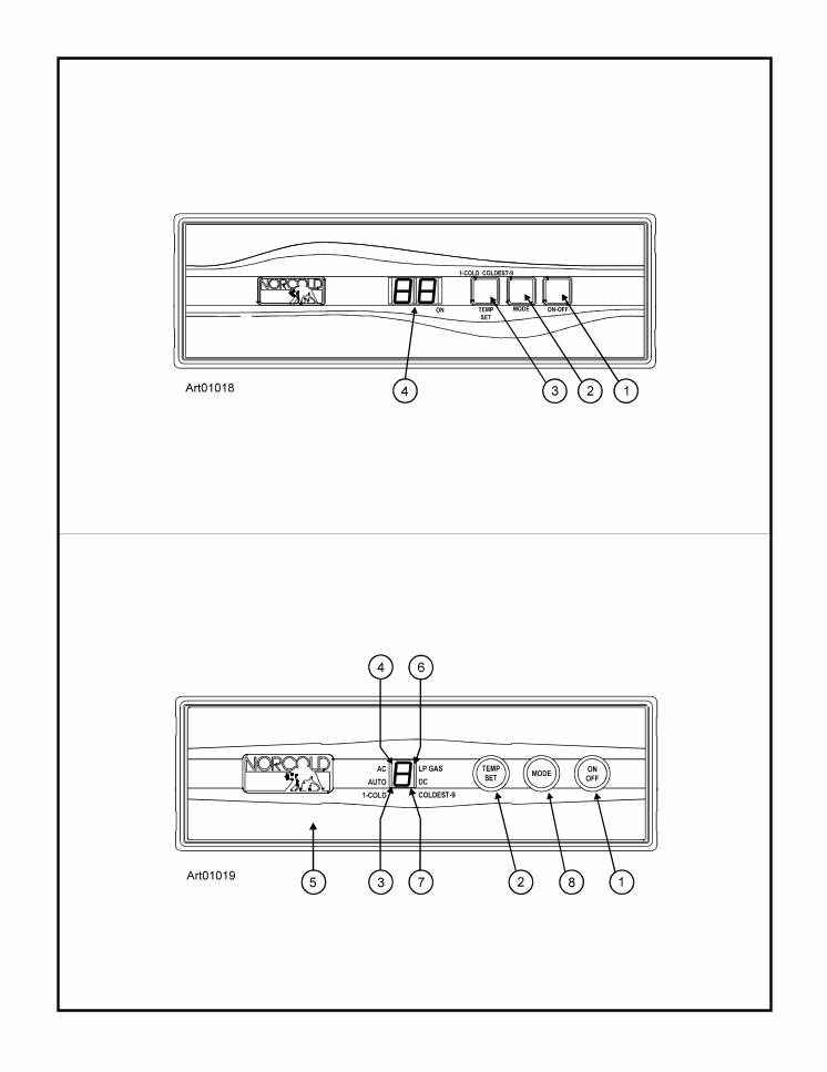
2. Push the MODE button [2] until “AU” appears in centerdisplay [4].
3. Push the TEMP SET button [3] as needed to set the thermo-stat at “4-6” temperature setting.
- If “AU” “AC” appears in the center display, it means that:
- 120 volt AC power is available to the refrigerator.
- The refrigerator is operating on AC electric power.
- After ten seconds, the “AU” “AC” goes off and only agreen dot “.” remains to show that the refrigerator isoperating.
- If “AU” “LP” appears in the center display, it means that:
- 120 volt AC power is not available to the refrigerator.
- The refrigerator is operating on propane gas.
- After ten seconds, the “AU” “LP” goes off and only agreen dot “.” remains to show that the refrigerator isoperating.
- On three-way models only, if “AU” “dc” appears in the centerdisplay, it means that:
- 120 volt AC power and propane gas are not available tothe refrigerator.
- The refrigerator is operating on DC power.
- After ten seconds, the “AU” “dc” goes off and only agreen dot “.” remains to show that the refrigerator isoperating.
Manual Mode Operation:
1. Push the ON/OFF button [1] to start the refrigerator.
2. Push the MODE button [2] until “LP” shows in the centerdisplay [4].
3. Push the TEMP SET button [3] to set the thermostat at “4-6”temperature setting.
4. The “LP” remains until you select a different operating modeor shut down the refrigerator.
Ignition and start up:(N62X, N62XX, N82X, and N82XXX models)(See Art01019)
NOTE: If the gas does not ignite in 30 seconds, the gas safetyvalve of the refrigerator automatically closes and thecontrols either select a different energy source and “F”appears in the center display or the controls change toStand By Mode.
Ignition and Start Up
Before ignition or start up of the refrigerator:
- Make sure the air flow in the lower intake vent, through therefrigerator coils and condenser, and out the upper exhaustvent is not blocked or decreased.
- Make sure there are no combustible materials in or aroundthe refrigerator.
Ignition and start up:(N64X, N64XXX, N64XIM, N64XIMXX, N84X,N84XXX, N84XIM, and N84XIMXX models)(See Art01018)
NOTE: If the gas does not ignite in 30 seconds, the gas safetyvalve of the refrigerator automatically closes and thecontrols either select a different energy source and“no” “FL” appears in the center display or the controlschange to Stand By Mode.
In Stand By Mode, an audible alarm starts and the code “no”“FL” appears in the center display. This means that the gas didnot ignite.
If the gas does not ignite after several attempts, refer to the“Fault Codes” section of this manual.
Automatic Mode Operation:
1. Push the ON/OFF button [1] to start the refrigerator.
Examine the gas supply system for leaks:
WARNING: Do not allow the leak detecting solution totouch the electrical components. Many liquids areelectrically conductive and can cause electrical shortsand in some cases, fire.
Use a leak detecting solution to examine the gas supply lineand all propane gas connections for leaks.
If you use compressed air for the test:
- The pressure of the compressed air at the manual shut offvalve of the refrigerator must not be more than 1/2 psig (14inches Water Column).
- If the pressure of the compressed air is more than 1/2 psig(14 inches Water Column), remove the gas supply linefrom the bulkhead fitting of the refrigerator before the test.
- If the pressure of the compressed air is equal to or lessthan 1/2 psig (14 inches Water Column), close the manualshut off valve of the refrigerator before the test.

Installation Manual 11
In Stand By Mode, the code “F” appears in the center display.This means that the gas did not ignite.
If the gas does not ignite after several attempts, refer to the“Fault Codes” section of this manual.
Automatic Mode Operation:
1. Push the ON/OFF button [1] to start the refrigerator.
2. Push the TEMP SET button [2] as needed to set the thermo-stat at “4-6” temperature setting.
- If the AUTO bar [3] and AC bar [4] appear in the centerdisplay [5], it means that:
- 120 volt AC power is available to the refrigerator.
- The refrigerator is operating on AC electric power.
- If the AUTO bar and the LP GAS bar [6] appear in the centerdisplay, it means that:
- 120 volt AC power is not available to the refrigerator.
- The refrigerator is operating on propane gas.
Manual Mode Operation:
1. Push the ON/OFF button [1] to start the refrigerator.
2. Push the MODE button [8] until the AUTO bar goes off andonly the LP GAS bar remains.
3. Push the TEMP SET button [2] as needed, to set the thermo-stat at “4-6” temperature setting.
4. The LP GAS bar remains until you select a different operatingmode or shut down the refrigerator.
Do a test of the gas safety valve:
1. Start up the refrigerator in the manual mode operation.
2. Open the lower intake vent.
3. Remove one wire from the solenoid of the gas safety valve atthe rear of the refrigerator.
4. Within 30 seconds, the flame should extinguish. Thismeans that the gas safety valve is operating correctly.
5. Put the wire back on the solenoid of the gas safety valve.
6. Close the lower intake vent.
Shut down - all models:
To shut down the refrigerator, push and hold the ON/OFF buttonfor two seconds.
Installation Manual 12
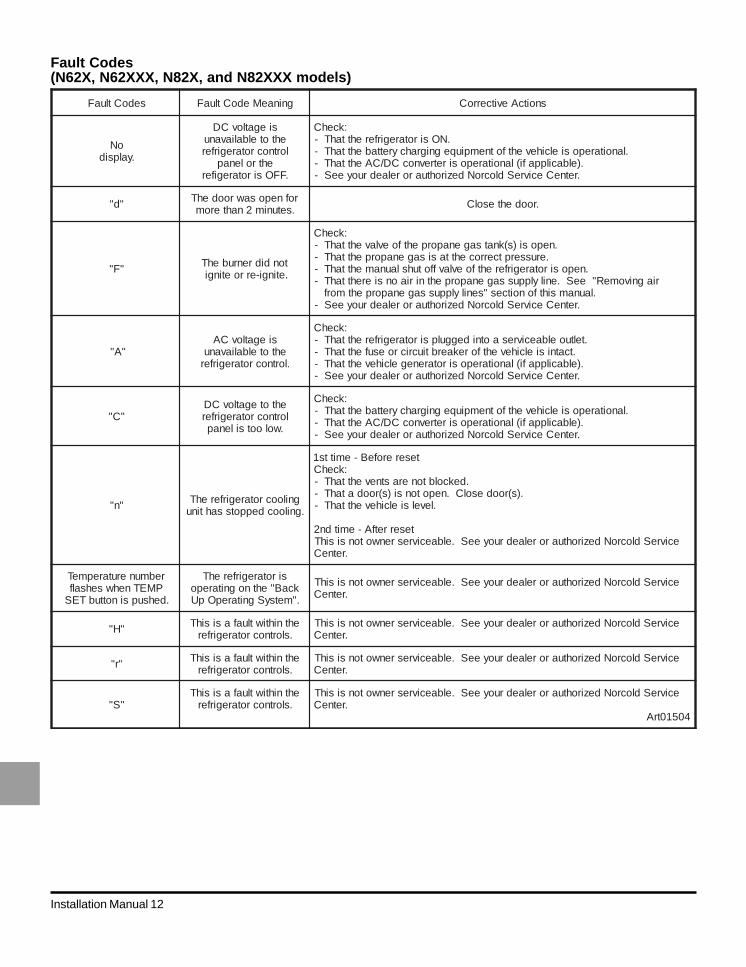
Fault Codes(N62X, N62XXX, N82X, and N82XXX models)
sedoCtluaF gninaeMedoCtluaF snoitcAevitcerroC
oN.yalpsid
siegatlovCDehtotelbaliavanu
lortnocrotaregirferehtrolenap
.FFOsirotaregifer
:kcehC.NOsirotaregirferehttahT-
.lanoitareposielcihevehtfotnempiuqegnigrahcyrettabehttahT-.)elbacilppafi(lanoitareposiretrevnocCD/CAehttahT-
.retneCecivreSdlocroNdezirohtuarorelaedruoyeeS-
"d" rofneposawroodehT.setunim2nahterom .roodehtesolC
"F" tondidrenrubehT.etingi-erroetingi
:kcehC.neposi)s(knatsagenaporpehtfoevlavehttahT-
.erusserptcerrocehttasisagenaporpehttahT-.neposirotaregirferehtfoevlavffotuhslaunamehttahT-
riagnivomeR"eeS.enilylppussagenaporpehtniriaonsierehttahT-.launamsihtfonoitces"senilylppussagenaporpehtmorf
.retneCecivreSdlocroNdezirohtuarorelaedruoyeeS-
"A"siegatlovCA
ehtotelbaliavanu.lortnocrotaregirfer
:kcehC.teltuoelbaecivresaotnideggulpsirotaregirferehttahT-
.tcatnisielcihevehtforekaerbtiucricroesufehttahT-.)elbacilppafi(lanoitareposirotarenegelcihevehttahT-
.retneCecivreSdlocroNdezirohtuarorelaedruoyeeS-
"C"ehtotegatlovCDlortnocrotaregirfer
.wolootsilenap
:kcehC.lanoitareposielcihevehtfotnempiuqegnigrahcyrettabehttahT-
.)elbacilppafi(lanoitareposiretrevnocCD/CAehttahT-.retneCecivreSdlocroNdezirohtuarorelaedruoyeeS-
"n" gniloocrotaregirferehT.gniloocdeppotssahtinu
tesererofeB-emitts1:kcehC
.dekcolbtonerastnevehttahT-.)s(roodesolC.nepotonsi)s(roodatahT-
.levelsielcihevehttahT-
teserretfA-emitdn2ecivreSdlocroNdezirohtuarorelaedruoyeeS.elbaecivresrenwotonsisihT
.retneC
rebmunerutarepmeTPMETnehwsehsalf
.dehsupsinottubTES
sirotaregirferehTkcaB"ehtnognitarepo."metsySgnitarepOpU
ecivreSdlocroNdezirohtuarorelaedruoyeeS.elbaecivresrenwotonsisihT.retneC
"H" ehtnihtiwtluafasisihT.slortnocrotaregirfer
ecivreSdlocroNdezirohtuarorelaedruoyeeS.elbaecivresrenwotonsisihT.retneC
"r" ehtnihtiwtluafasisihT.slortnocrotaregirfer
ecivreSdlocroNdezirohtuarorelaedruoyeeS.elbaecivresrenwotonsisihT.retneC
"S"ehtnihtiwtluafasisihT
.slortnocrotaregirferecivreSdlocroNdezirohtuarorelaedruoyeeS.elbaecivresrenwotonsisihT
.retneC40510trA
Installation Manual 13
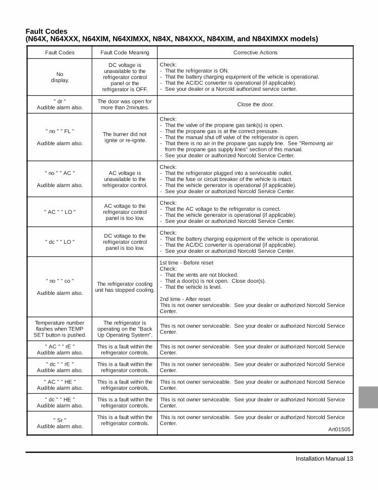
Fault Codes(N64X, N64XXX, N64XIM, N64XIMXX, N84X, N84XXX, N84XIM, and N84XIMXX models)
sedoCtluaF gninaeMedoCtluaF snoitcAevitcerroC
oN.yalpsid
siegatlovCDehtotelbaliavanu
lortnocrotaregirferehtrolenap
.FFOsirotaregirfer
:kcehC.NOsirotaregirferehttahT-
.lanoitareposielcihevehtfotnempiuqegnigrahcyrettabehttahT-.)elbacilppafi(lanoitareposiretrevnocCD/CAehttahT-.retnececivresdezirohtuadlocroNarorelaedruoyeeS-
"rd".oslamralaelbiduA
rofneposawroodehT.setunim2nahterom .roodehtesolC
"LF""on"
.oslamralaelbiduA
tondidrenrubehT.etingi-erroetingi
:kcehC.neposi)s(knatsagenaporpehtfoevlavehttahT-
.erusserptcerrocehttasisagenaporpehttahT-.neposirotaregirferehtfoevlavffotuhslaunamehttahT-
riagnivomeR"eeS.enilylppussagenaporpehtniriaonsierehttahT-.launamsihtfonoitces"senilylppussagenaporpehtmorf
.retneCecivreSdlocroNdezirohtuarorelaedruoyeeS-
"CA""on"
.oslamralaelbiduA
siegatlovCAehtotelbaliavanu
.lortnocrotaregirfer
:kcehC.teltuoelbaecivresaotnideggulprotaregirferehttahT-.tcatnisielcihevehtforekaerbtiucricroesufehttahT-
.)elbacilppafi(lanoitareposirotarenegelcihevehttahT-.retneCecivreSdlocroNdezirohtuarorelaedruoyeeS-
"OL""CA"ehtotegatlovCA
lortnocrotaregirfer.wolootsilenap
:kcehC.tcerrocsirotaregirferehtotegatlovCAehttahT-
.)elbacilppafi(lanoitareposirotarenegelcihevehttahT-.retneCecivreSdlocroNdezirohtuarorelaedruoyeeS-
"OL""cd"ehtotegatlovCDlortnocrotaregirfer
.wolootsilenap
:kcehC.lanoitareposielcihevehtfotnempiuqegnigrahcyrettabehttahT-
.)elbacilppafi(lanoitareposiretrevnocCD/CAehttahT-.retneCecivreSdlocroNdezirohtuarorelaedruoyeeS-
"oc""on"
.oslamralaelbiduA
gniloocrotaregirferehT.gniloocdeppotssahtinu
tesererofeB-emitts1:kcehC
.dekcolbtonerastnevehttahT-.)s(roodesolC.nepotonsi)s(roodatahT-
.levelsielcihevehttahT-
teserretfA-emitdn2ecivreSdlocroNdezirohtuarorelaedruoyeeS.elbaecivresrenwotonsisihT
.retneC
rebmunerutarepmeTPMETnehwsehsalf
.dehsupsinottubTES
sirotaregirferehTkcaB"ehtnognitarepo."metsySgnitarepOpU
ecivreSdlocroNdezirohtuarorelaedruoyeeS.elbaecivresrenwotonsisihT.retneC
"Er""CA".oslamralaelbiduA
ehtnihtiwtluafasisihT.slortnocrotaregirfer
ecivreSdlocroNdezirohtuarorelaedruoyeeS.elbaecivresrenwotonsisihT.retneC
"Er""cd".oslamralaelbiduA
ehtnihtiwtluafasisihT.slortnocrotaregirfer
ecivreSdlocroNdezirohtuarorelaedruoyeeS.elbaecivresrenwotonsisihT.retneC
"EH""CA".oslamralaelbiduA
ehtnihtiwtluafasisihT.slortnocrotaregirfer
ecivreSdlocroNdezirohtuarorelaedruoyeeS.elbaecivresrenwotonsisihT.retneC
"EH""cd".oslamralaelbiduA
ehtnihtiwtluafasisihT.slortnocrotaregirfer
ecivreSdlocroNdezirohtuarorelaedruoyeeS.elbaecivresrenwotonsisihT.retneC
"rS".oslamralaelbiduA
ehtnihtiwtluafasisihT.slortnocrotaregirfer
ecivreSdlocroNdezirohtuarorelaedruoyeeS.elbaecivresrenwotonsisihT.retneC
50510trA