Embed Size (px)
Citation preview

DAIKIN ROOM AIR CONDITIONER
INSTALLATION MANUALR410A Split Series
Installation manualManuel dinstallation
Manual de instalación
Eng
lish
Fran
çais
Esp
añol
MODELS
FDXS09LVJUFDXS12LVJU
CDXS15LVJUCDXS18LVJUCDXS24LVJU
Manuel dinstallation
00_CV_3P297301-3C.indd 1 10/26/2012 11:23:56 AM

Eng
lish
■English 1
Safety Precautions•ReadtheseSafetyPrecautionscarefullytoensurecorrectinstallation.•ThismanualclassifiestheprecautionsintoDANGER,WARNINGandCAUTION.Besuretofollowalltheprecautionsbelow:theyareallimportantforensuringsafety.
DANGER ..........Indicates an imminently hazardous situation which, if not avoided, will result in death or serious injury.
WARNING ........Failure to follow any of WARNING is likely to result in such grave consequences as death or serious injury.
CAUTION .........Failure to follow any of CAUTION may in some cases result in grave consequences.
•Thefollowingsafetysymbolsareusedthroughoutthismanual:
Besuretoobservethisinstruction. Besuretoestablishanearthconnection. Neverattempt.
•Aftercompletinginstallation,testtheunittocheckforinstallationerrors.Givetheuseradequateinstructionscon-cerningtheuseandcleaningoftheunitaccordingtotheOperationManual.
DANGER•Refrigerantgasisheavierthanairandreplacesoxygen.Amassiveleakcouldleadtooxygendepletion,especiallyinbasements,andanasphyxiationhazardcouldoccurleadingtoseriousinjuryordeath.
•Iftherefrigerantgasleaksduringinstallation,ventilatetheareaimmediately.Refrigerantgasmayproduceatoxicgasifitcomesincontactwithfiresuchasfromafanheater,stoveorcookingdevice.Exposuretothisgascouldcausesevereinjuryordeath.
•Aftercompletingtheinstallationwork,checkthattherefrigerantgasdoesnotleak.Refrigerantgasmayproduceatoxicgasifitcomesincontactwithfiresuchasfromafanheater,stoveorcookingdevice.Exposuretothisgascouldcausesevereinjuryordeath.
•Donotgroundunitstowaterpipes,telephonewiresorlightningrodsbecauseincompletegroundingcouldcauseasevereshockhazardresultinginsevereinjuryordeath,andtogaspipesbecauseagasleakcouldresultinanexplosionwhichcouldleadtosevereinjuryordeath.
•Safelydisposeofthepackingmaterials.Packingmaterials,suchasnailsandothermetalorwoodenparts,maycausestabsorotherinjuries.Tearapartandthrowawayplasticpackagingbagssothatchildrenwillnotplaywiththem.Childrenplayingwithplasticbagsfacethedangerofdeathbysuffocation.
•Donotinstallunitinanareawhereflammablematerialsarepresentduetoriskofexplosionresultinginseriousinjuryordeath.
•Donotgroundunitstotelephonewiresorlightningrodsbecauselightningstrikescouldcauseasevereshockhazardresultinginsevereinjuryordeath,andtogaspipesbecauseagasleakcouldresultinanexplosionwhichcouldleadtosevereinjuryordeath.
WARNING•Installationshallbelefttotheauthorizeddealeroranothertrainedprofessional.Improperinstallationmaycausewaterleakage,electricalshock,fire,orequipmentdamage.
•Installtheairconditioneraccordingtotheinstructionsgiveninthismanual.Incompleteinstallationmaycausewaterleakage,electricalshock,fireorequipmentdamage.
•Besuretousethesuppliedorexactspecifiedinstallationparts.Useofotherpartsmaycausetheunittocometolose,waterleakage,electricalshock,fireorequipmentdamage.
•Installtheairconditioneronasolidbasethatislevelandcansupporttheweightoftheunit.Aninadequatebaseorincompleteinstallationmaycauseinjuryorequipmentdamageintheeventtheunitfallsoffthebaseorcomesloose.
•Electricalworkshallbecarriedoutinaccordancewiththeinstallationmanualandthenational,stateandlocalelectricalwiringcodes.Insufficientcapacityorincompleteelectricalworkmaycauseelectricalshock,fireorequipmentdamage.
•Besuretouseadedicatedpowercircuit.Neveruseapowersupplysharedbyanotherappliance.Followallappropriateelectricalcodes.
•Forwiring,useawireorcablelongenoughtocovertheentiredistancewithnosplicesifpossible.Donotuseanextensioncord.Donotputotherloadsonthepowersupply.Useonlyaseparatededicatedpowercircuit.(Failuretodosomaycauseabnormalheat,electricshock,fireorequipmentdamage.)
•Usethespecifiedtypesofwiresforelectricalconnectionsbetweentheindoorandoutdoorunits.Followallstateandlocalelectricalcodes.Firmlyclamptheinterconnectingwiressotheirterminalsreceivenoexternalstresses.Incompleteconnectionsorclampingmaycauseterminaloverheating,fireorequipmentdamage.
01_EN_3P297301-3C.indd 1 10/26/2012 11:27:22 AM

2 ■English
Safety Precautions WARNING
•Afterconnectingallwiringbesuretoshapethecablessothattheydonotputunduestressontheelectricalcovers,panelsorterminals.Installcoversoverthewires.Incompletecoverinstallationmaycauseterminaloverheating,electricalshock,fireorequipmentdamage.
•Wheninstallingorrelocatingthesystem,besuretokeeptherefrigerantcircuitfreefromallsubstancesotherthanthespecifiedrefrigerant(R410A),suchasair.(Anypresenceofairorotherforeignsubstanceintherefrigerantcircuitcausesanabnormalpressurerisewhichmayresultinrupture,resultingininjury.)
•Duringpump-down,stopthecompressorbeforeremovingtherefrigerantpiping.Ifthecompressorisstillrunningandtheshut-offvalveisopenduringpump-down,airwillbesuckedinwhentherefrigerantpipingisremoved,causingabnormallyhighpressurewhichcouldleadtoequipmentdamageorandpersonalinjury.
•Duringinstallation,attachtherefrigerantpipingsecurelybeforerunningthecompressor.Iftherefrigerantpipesarenotattachedandtheshut-offvalveisopenwhenthecompressorisrun,airwillbesuckedin,causingabnormalpressureintherefrigerationcycle,whichmayresultinequipmentdamageandeveninjury.
•Installaleakcircuitbreaker,asrequired.Ifaleakcircuitbreakerisnotinstalled,electricshockmayresult.
•Besuretoinstallagroundfaultcircuitinterrupterbreaker.Failuretoinstallagroundfaultcircuitinterrupterbreakermayresultinelectricallyshocksorpersonalinjury.
CAUTION•Establishdrainpipingaccordingtotheinstructionsofthismanual.Inadequatepipingmaycausewaterdamage.
•Noteforinstallingtheoutdoorunit.(Forheatpumpmodelonly.)Inregionsofthecountrywheretheoutsidetemperatureisatorbelowthefreezingpoint,thedrainmayfreeze.Ifso,itisrecommendedthatanelectricheaterbeinstalledinordertoprotectthedrainfromfreezing.
•Tightentheflarenutaccordingtothespecifiedtorque.Atorquewrenchshouldbeused.Iftheflarenutistightenedtoomuch,theflarenutmaycrackovertimeandcauserefrigerantleakage.
•Donottouchtheheatexchangerfins.Improperhandlingmayresultininjury.
•Beverycarefulaboutproducttransportation.SomeproductsusePPbandsforpackaging.DonotuseanyPPbandsforameansoftransportation.Itisdangerous.
Accessories
Wireless remote
controller
1 pc.
Screws for conduit
mounting plate
2 pcs.
Insulation tube
1 pc.
Dry battery AAA. LR03 (alkaline)
Mounting frame Screws
M4 × 25
Decorative cover
Remote controller
holder
1 pc.1 pc. 1 pc.
Receiver kitAir filter
1 set 1 pc. 2 pcs.
2 pcs.
Clamp metal
1 pc. 1 pc.
Insulation for fitting
1 each
Sealing pad
Large and small
1 each
for gas pipe
for liquid pipe One is spare
Large
Small24 pcs.4 pcs.
Washer for hanger bracket
8 pcs. 2 pcs. 6 pcs. 1 set
Drain hose Sealingmaterial
Clamp Washer fixing plate
1 set
Screws for duct flanges
Stored in outlet vent
1 pc.
Hanger (right)
insulation
[ Other ] • Operation manual • Installation manual
1 pc.
Conduit mounting
plate
3 pcs. (only for CDXS)
2 large
1 small
01_EN_3P297301-3C.indd 2 10/26/2012 11:27:22 AM
Eng
lish
■English 3
Choosing an Installation Site•Beforechoosingtheinstallationsite,obtainuserapproval.
1. Indoor unit
CAUTION•Whenmovingtheunitduringorafterunpacking,makesuretoliftitbyholdingitsliftinglugs.Donotexertanypressureonotherparts,especiallytherefrigerantpiping,drainpipingandflangeparts.Wearprotectivegear(suchasgloves)wheninstallingtheunit.
•Ifyouthinkthehumidityinsidetheceilingmightexceed86°F(30°C)andRH80%,reinforcetheinsulationontheunitbody.Useglasswoolorpolyethylenefoamasinsulationsothatthethicknessismorethan0.4in(10mm)andfitsinsidetheceilingopening.
•Optimumairdistributionisensured.•Theairpassageisnotblocked.•Condensatecandrainproperly.•Theceilingisstrongenoughtobeartheweightoftheindoorunit.•Afalseceilingdoesnotseemtobeatanincline.•Sufficientclearanceformaintenanceandservicingisensured.•Pipingbetweentheindoorandoutdoorunitsiswithintheallowablelimits.(Refertotheinstallationmanualfortheoutdoorunit.)
•Theindoorunit,outdoorunit,powersupplywiringandtransmissionwiringisatleast3.3ft(1m)awayfromtelevisionsandradios.Thispreventsimageinterfer-enceandnoiseinelectricalappliances.(Noisemaybegenerateddependingontheconditionsunderwhichtheelectricwaveisgenerated,evenifa3.3ft(1m)allowanceismaintained.)
■Use suspension bolts to install the unit. Check whether or not the ceiling is strong enough to support the weight of the unit. If there is a risk that the ceiling is not strong enough, reinforce the ceiling before installing the unit.(Installationpitchismarkedonthecartonboxforinstallation.Refertoittocheckforpointsrequiringreinforcing.)Selectthe*Hdimensionsuchthatadownwardslopeofatleast1/100isensuredasindicatedin“Drain Piping Work”.•Theinstallationpitchislistedonthepackingmaterial,andshouldbecheckedwhendecidingwhethertoreinforcethelocationornot.
Control box Maintenancespace
12 (300)or more
13/16 (20) or more
100
(250
0)
or m
ore
*H=
9-1/
2 (2
40)
or m
ore
7-7/
8 (2
00)
Ceiling
Floor surface
(unit : in (mm))
If th
ere
is
no c
eilin
g
■ Select the signal receiver mounting location according to the following conditions:•Installthesignalreceiver,whichhasabuilt-intemperaturesensor,neartheintakeventwherethereisconvectionofairanditcangetanaccuratereadingoftheroom’stemperature.If theintakeventisinanotherroomortheunitcannotbeinstalledneartheintakeventforanyotherreason,installit5ft(1.5m)abovetheflooronawallwherethereisconvection.
•Inordertogetanaccuratereadingoftheroom’stemperature,installthesignalreceiverinalocationwhereitisnotexposeddirectlytocoldorhotairfromtheairdischargegrilleortodirectsunlight.
•Sincethereceiverhasabuilt-inlightreceptortoreceivesignalsfromthewirelessremotecontroller,donotmountitinalocationwherethesignalmaybeblockedbyacurtain,etc.
Air outlet grille: Wooden or plastic grille is recommended because condensation may occur depending on humidity conditions.
CAUTIONIfthesignalreceiverisnotinstalledinalocationwherethereisconvectionofair,itmaybeunabletogetanaccuratereadingoftheroom’stemperature.
01_EN_3P297301-3C.indd 3 10/26/2012 11:27:23 AM

4 ■English
Choosing an Installation Site2. Wireless remote controller
•Turnonallthefluorescentlampsintheroom,ifany,andfindthesitewhereremotecontrollersignalsareproperlyreceivedbytheindoorunit(within13ft(4m)).
3. Outdoor unit•Foroutdoorunitinstallation,seetheinstallationmanualsuppliedwiththeoutdoorunit.
Preparations before Installation ■Relation of the unit to the suspension bolt positions. •Installtheinspectionopeningonthecontrolboxsidewheremaintenanceandinspectionofthecontrolboxareeasy.Installtheinspectionopeningalsointhelowerpartoftheunit.
■Make sure the range of the unit’s external static pres-sure is not exceeded.(Seethetechnicaldocumentationfortherangeoftheexternalstaticpressuresetting.)
■Open the installation hole. (Pre-set ceilings)•Oncetheinstallationholeisopenedintheceilingwheretheunitistobeinstalled,passrefrigerantpiping,drainpiping,transmis-sionwiring,andremotecontrollerwiring(unneededifusingawirelessremotecontroller)totheunit’spipingandwiringholes.See“Refrigerant Piping Work”,“Drain Piping Work”,and“Wiring”.
•Afteropeningtheceilinghole,makesureceilingislevelifneeded.Itmightbenecessarytoreinforcetheceilingframetopreventshaking.Consultanarchitectorcarpenterfordetails.
■ Install the suspension bolts.(UseW3/8toM10suspensionbolts.)•Useahole-in-anchor,sunkeninsert,sunkenanchorforexistingceilings,andasunkeninsert,sunkenanchororotherparttobeprocuredinthefieldtoreinforcetheceilingtobearingtheweightoftheunit.(RefertoFig.)
19-11/16 (500)
17-3/4 (450)
(Inspection opening size)
Air outlet
Suspensionbolt pitch
(unit : in (mm))
Air inlet
Control box
(Sus
pens
ion
bolt
pitc
h)
Ceiling
24-7/16 (620)
24-7/16 (620)
A
Arrow view Inspection door
(Ceiling opening)
<SERVICE SPACE>
A B
FDXS09/12 CDXS15/18A 27-9/16 (700)B 29-1/8 (740) 37 (940)
35-7/16 (900)CDXS24
44-7/8 (1140)43-5/16 (1000)
Note: All the above parts are field supplied.
Suspension bolt
Long nut or turn-buckle
Anchor bolt
Indoor unit
Ceiling slab
■Mount chamber cover and air filter (acces-sory).Forbottomintake,replacethechambercoverandtheprotectionnetintheprocedurelistedinFig.(1)Removetheprotectionnet.(6locations)
Removethechambercover.(7locations)(2)Reattachtheremovedchambercoverinthe
orientationshowninFig.(7locations)ReattachtheremovedprotectionnetintheorientationshowninFig.(6locations)RefertoFig.forthedirectionoftheprotectionnet.
Air inlet
Air inlet
(1)
Chamber cover
(2)
Air outletAir outlet
Chamber cover
Protection net
Protection net
01_EN_3P297301-3C.indd 4 10/26/2012 11:27:23 AM
Eng
lish
■English 5
(3)Attachsealingpadasshownintherightfigure.(Storedinoutletvent)(onlyforCDXS)(Inordertotakeintheairinsidetheceiling,andwhennottakinginairfromoutdoorair,itisnotnecessarytostick.)•Attachthesealingpad(accessory)totheplatemetalsectionswhicharenotcoveredbyanti-sweatmaterial.
•Makesuretherearenogapsbetweenthedifferentpiecesofsealingpad.
Air inlet
(3)
Air outlet Air outlet
Air inlet
Anti-sweat material included with the product
Anti-sweat material included with the product
Sealing pad (Small)
For rear intake type
Sealing pad (Large)
Sealing pad (Small)(accessory) (accessory)
Sealing pad (Large)
(accessory) (accessory)
For bottom intake type
(4)Attachthehanger(right)insulationtotherighthanger.(Storedinoutletvent)(Seethebelowfigureforthestickingbaseline.)
Hanger (right) insulation(accessory)
SlitStick
ing base line
Hanger bracket (right)
Arrow view
(5)Attachtheairfilter(accessory)inthemannershowninthediagram.
In case of bottom side In case of back side
FilterPush
Push
Main unit
Attach the filter to the main unit while pushing down on the bends. *
* FDXS09/12, CDXS15/18 : 2 bends CDXS24 : 3 bends
■When two indoor units are installed in one room, one of the two wireless remote controllers can be easily set for another addresses.
J4 ADDRESSEXIST 1CUT 2
PCB in the indoor unit • Cut the jumper JA on PCB.
• Cut the jumper J4.
Wireless remote controller
1 2 3
JAADDRESS:
CUTEXIST 1
2ADDRESSJA
JBJC
J4
01_EN_3P297301-3C.indd 5 10/26/2012 11:27:24 AM
6 ■English
Indoor Unit Installation<< As for the parts to be used for installation work, be sure to use the provided accessories and specified
parts designated by our company. >>
■ Install the indoor unit temporarily. •Attachthehangerbrackettothesuspensionbolt.Besuretofixitsecurelybyusinganutandwasherfromtheupperandlowersidesofthehangerbracket.(RefertoFig.)
[ PRECAUTION ]Sincetheunitusesaplasticdrainpan,preventweldingspatterandotherforeignsubstancesfromenteringtheoutletholeduringinstallation.
■Adjust the height of the unit.
■Check the unit is horizontally level.
[ How to secure washers ]
Insert below washer
Washer fixing plate
(accessory)
Part to be procured in the field
[ Securing the hanger bracket ]
Washer for hanging bracket
Hanger bracket
Tighten(double nut)
(accessory)
Vinyl tubeLevel
CAUTION•Makesuretheunitisinstalledlevelusingaleveloraplastictubefilledwithwater.Inusingaplastictubeinsteadofalevel,adjustthetopsurfaceoftheunittothesurfaceofthewateratbothendsoftheplastictubeandadjusttheunithorizontally.(Onethingtowatchoutforinparticularisifitisinstalledsothattheslopeisnotinthedirectionofthedrainpiping,asthismightcauseleaking.)
■ Tighten the upper nut.
■Mounting the receiver.Mountthereceiverasshownbelow.
1 Press the receiver into the mounting frame.
2 Mount the completed assembly using two screws.
3 Press the decorative cover into the mounting frame.
Note) Mount the Remote controller cord far enough away from strong electrical wires (such as distribution wires for electrical lights, air conditioners, etc.) and from weak electrical wires (such as wires for telephones, intercoms, etc.).
For heat pump: If your feet feel cold when using the heating function, it is recommended that the air outlet grille shown at below be attached.
(Adjustable angle)45°
Outdoor unit InstallationInstallasdescribedintheinstallationmanualsuppliedwiththeoutdoorunit.
01_EN_3P297301-3C.indd 6 10/26/2012 11:27:25 AM
Eng
lish
■English 7
Refrigerant Piping WorkSeetheinstallationmanualsuppliedwiththeoutdoorunit.
1. Flaring the pipe end1)Cutthepipeendwithapipecutter.2)Removeburrswiththecutsurfacefacingdown-
wardsothatthechipsdonotenterthepipe.3)Puttheflarenutonthepipe.4)Flarethepipe.5)Checkthattheflaringisproperlymade.
A
A
(Cut exactly at right angles.) Remove burrs
Flare’s inner surface must be flaw-free.
The pipe end must be evenly flared in a perfect circle.
Make sure that the flare nut is fitted.
Check
0-0.02in (0-0.5mm) 0.04-0.06in (1.0-1.5mm) 0.06-0.08in (1.5-2.0mm)
Set exactly at the position shown below.
Clutch-type
Flare tool for R410A
Clutch-type (Rigid-type) Wing-nut type (Imperial-type)
Conventional flare tool
Flaring
Die
WARNING•Donotusemineraloilonflaredpart.•Preventmineraloilfromgettingintothesystemasthiswouldreducethelifetimeoftheunits.•Neverusepipingwhichhasbeenusedforpreviousinstallations.Onlyusepartswhicharedeliveredwiththeunit.•NeverinstalladriertothisR410Aunitinordertoguaranteeitslifetime.•Thedryingmaterialmaydissolveanddamagethesystem.Incompleteflaringmaycauserefrigerantgasleakage.
2. Refrigerant piping1)Topreventgasleakage,applyrefrigerationmachineoiltotheinner
surfaceoftheflare.(UserefrigerationoilforR410A)
2)Alignthecentersofbothflaresandtightentheflarenuts3or4turnsbyhand.Thentightenthemfullywiththetorquewrenches.•Usetorquewrencheswhentighteningtheflarenutstopreventdamagetotheflarenutsandescapinggas.
Flarenuttighteningtorque
Gasside Liquidside
3/8inch(9.5mm)
1/2inch(12.7mm)
5/8inch(15.9mm)
1/4inch(6.4mm)
24.1-29.4ft•lbf(32.7-39.9N•m)
36.5-44.5ft•lbf(49.5-60.3N•m)
45.6-55.6ft•lbf(61.8-75.4N•m)
10.4-12.7ft•lbf(14.2-17.2N•m)
CAUTION•Overtightening may damage the flare and cause leaks.
3) After the work is finished, make sure to check that there is no gas leak. Torque wrench
Piping union
Flare nutSpanner
Do not apply refrigeration oil to the outer surface.
Flare nut
Apply refrigeration
oil to the inner
surface of the flare.
Do not apply refrigeration oil to the flare nut to avoid tightening with excessive torque.
4) After checking for gas leaks, be sure to insulate the pipe connections.•Insulateusingtheinsulationforfittingincludedwiththeliquidandgaspipes.Besides,makesuretheinsulationforfittingontheliquidandgaspipinghasitsseamsfacingup.(Tightenbothedgeswithclamp.)
•Forthegaspiping,wrapthemediumsealingpadovertheinsulationforfitting(flarenutpart).
Gas pipe
Liquid pipe
Piping insulation material (main unit)
Attach to baseFlare nut connection
Turn seams up
Insulation for fitting
(accessory)Clamp
Piping insulation material(Field supplied)
Gas Piping Insulation Procedure
(accessory)
Main unit
Clamp (accessory)
Flare nut connection
Turn seams up
Piping insulation material(Field supplied)
Piping insulation material (main unit)
Attach to base
Main unit
Insulation for fitting (accessory)
Liquid Piping Insulation Procedure
Small sealing pad
Measure the length of the gas pipe as you will have to cover it with the sealing tape.
(accessory)
Wrap the sealing tape around the gas pipe.
Main unit
01_EN_3P297301-3C.indd 7 10/26/2012 11:27:25 AM

8 ■English
Refrigerant Piping WorkCAUTION
Besuretoinsulateanyfieldpipingallthewaytothepipingconnectioninsidetheunit.Anyexposedpipingmaycausecondensa-tionorburnsiftouched.
Cautions on Pipe Handling•Protecttheopenendofthepipeagainstdustandmoisture.(Tightenbothedgeswithclamp.)
•Allpipebendsshouldbeasgentleaspossible.Useapipebenderforbending.(Seetheminimumbendradiusinthetablebelow.)
Wall
If no flare cap is available, cover the flare mouth with tape to keep dirt or water out.
Be sure to place a cap.
Rain
Selection of Copper and Heat Insulation materialsWhenusingcommercialcopperpipesandfittings,observethefollowing:•Insulationmaterial:PolyethylenefoamHeattransferrate:0.041to0.052W/mK(0.024to0.030Btu/fth°F(0.035to0.045kcal/mh°C))BesuretouseinsulationthatisdesignedforusewithHVACSystems.
•Besuretoinsulateboththegasandliquidpipingandtoprovideinsulationdimensionsasbelow.
Gasside Liquidside GaspipethermalinsulationLiquidpipethermalinsulation
O.D.3/8inch(9.5mm)
O.D.1/2inch(12.7mm)
O.D.5/8inch(15.9mm)
O.D.1/4inch(6.4mm)
I.D.15/32-19/32inch(12-15mm)
I.D.9/16-5/8inch(14-16mm)
I.D.5/8-25/32inch(16-20mm)
I.D.5/16-13/32inch(8-10mm)
Minimumbendradius Thickness13/32inch(10mm)Min.
1-3/16inch(30mm)ormore
1-9/16inch(40mm)ormore
1-15/16inch(50mm)ormore
1-3/16inch(30mm)ormore
Thickness0.031inch(0.8mm)(C1220T-O)
Thickness0.039inch(1.0mm)(C1220T-O)
Thickness0.031inch(0.8mm)(C1220T-O)
Also,whensubjecttohighhumidity,heatinsulationoftherefrigerantpiping(theunitpipingandbranchpiping)mustbefurtherreinforced.Reinforcetheinsulationwheninstallingtheunitnearbathrooms,kitchens,andothersimilarlocations.Refertothefollowing:•86°F(30°C),morethan75%RH:13/16inch(20mm)Min.inthicknessIftheinsulationisnotsufficient,condensationmayformonthesurfaceoftheinsulation.
•Useseparatethermalinsulationpipesforgasandliquidrefrigerantpipes.
Gas pipeLiquid pipe
Gas pipe insulation
Liquid pipe insulation
Finishing tape Drain hose
Drain Piping WorkCAUTION
Makesureallwaterisoutbeforemakingtheductconnection.
■ Install the drain piping.•Makesurethedrainworksproperly.•Thediameterofthedrainpipeshouldbegreaterthanorequaltothediameteroftheconnectingpipe(vinyltube;pipesize:25/32inch(20mm);outerdimension:1-1/32inch(26mm)).
Drain pipe connection hole
Refrigerant pipes
Connect the drain pipe after removing the rubber cap and insulation tubing attached to the connection hole.
•Keepthedrainpipeshortandslopingdownwardsatagradientofatleast1/100topreventairpocketsfromforming.
OK
Wrong
01_EN_3P297301-3C.indd 8 10/26/2012 11:27:26 AM
Eng
lish
■English 9
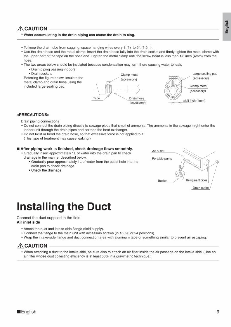
CAUTION•Water accumulating in the drain piping can cause the drain to clog.
•Tokeepthedraintubefromsagging,spacehangingwiresevery3(1)to5ft(1.5m).•Usethedrainhoseandthemetalclamp.Insertthedrainhosefullyintothedrainsocketandfirmlytightenthemetalclampwiththeupperpartofthetapeonthehoseend.Tightenthemetalclampuntilthescrewheadislessthan1/8inch(4mm)fromthehose.
•Thetwoareasbelowshouldbeinsulatedbecausecondensationmayformtherecausingwatertoleak.•Drainpipingpassingindoors•Drainsockets
Referringthefigurebelow,insulatethemetalclampanddrainhoseusingtheincludedlargesealingpad.
ϕ1/8 inch (4mm)
Large sealing pad
Clamp metal
(accessory)
(accessory)Clamp metal
Drain hoseTape
(accessory)
(accessory)
<PRECAUTIONS>
Drainpipingconnections•Donotconnectthedrainpipingdirectlytosewagepipesthatsmellofammonia.Theammoniainthesewagemightentertheindoorunitthroughthedrainpipesandcorrodetheheatexchanger.
•Donottwistorbendthedrainhose,sothatexcessiveforceisnotappliedtoit.(Thistypeoftreatmentmaycauseleaking.)
■After piping work is finished, check drainage flows smoothly.•Graduallyinsertapproximately1Lofwaterintothedrainpantocheckdrainageinthemannerdescribedbelow.
•Graduallypourapproximately1Lofwaterfromtheoutletholeintothedrainpantocheckdrainage.
•Checkthedrainage.
Portable pump
Refrigerant pipesBucket
Air outlet
Drain outlet
Installing the DuctConnecttheductsuppliedinthefield.Air inlet side
•Attachtheductandintake-sideflange(fieldsupply).•Connecttheflangetothemainunitwithaccessoryscrews(in16,20or24positions).•Wraptheintake-sideflangeandductconnectionareawithaluminumtapeorsomethingsimilartopreventairescaping.
CAUTION•Whenattachingaducttotheintakeside,besurealsotoattachanairfilterinsidetheairpassageontheintakeside.(Useanairfilterwhosedustcollectingefficiencyisatleast50%inagravimetrictechnique.)
01_EN_3P297301-3C.indd 9 10/26/2012 11:27:26 AM

10 ■English
Installing the DuctOutlet side
•Connecttheductaccordingtotheinsideoftheoutlet-sideflange.•Wraptheoutlet-sideflangeandtheductconnectionareawithaluminumtapeorsomethingsimilartopreventairescaping.
Main unit
Air inlet side Outlet side
Connection screw(accessory)
(field supply)
(field supply)
(field supply)
(field supply)
Flange
Flange
Aluminum tape
Aluminum tape
Insulation material
CAUTION•Besuretoinsulatetheducttopreventcondensationfromforming.(Material:glasswoolorpolyethylenefoam,1inch(25mm)thick)
•Useelectricinsulationbetweentheductandthewallwhenusingmetalductstopassmetallathsofthenetorfenceshapeormetalplatingintowoodenbuildings.
WiringSeetheinstallationmanualsuppliedwiththeoutdoorunit.
■HOW TO CONNECT WIRINGS.•WireonlyafterremovingthecontrolboxcoverasshownintheFig.
*Remote controller wiring
Control box cover
Wiring Diagram(rear)
Conduit mounting plate(accessory)
Conduit(field supply)
Lock nut(field supply)
Screw(accessory)
Power supply wiringGround wire
• Wrap the power supply wiring and the remote controller wiring with the sealing material as shown in the figure below.(Otherwise, moisture or small creatures such as insects from the outside may cause short-circuit inside the control box.)Attach securely so that there are no gaps.
Insideunit
Outsideunit
[How to adhere it]
Wire
(accessory)Sealing material Wiring
through hole
01_EN_3P297301-3C.indd 10 10/26/2012 11:27:26 AM
Eng
lish
■English 11
CAUTION•Whendoingthewiring,makesurethewiringisneatanddoesnotcausethecontrolboxcovertostickup,thenclosethecoverfirmly.Whenattachingthecontrolboxcover,makesureyoudonotpinchanywires.
•Outsidetheunit,separatethelowvoltagewiring(remotecontrollerwiring)andhighvoltagewiring(groundwireandpowersupplywiring)atleast5insothattheydonotpassthroughthesameplacetogether.Proximitymaycauseelectricalinterfer-ence,malfunctions,andbreakage.
[ PRECAUTION ]
•Seealsothe“ElectricalWiringDiagramLabel”whenwiringtheunitforpowersupply.
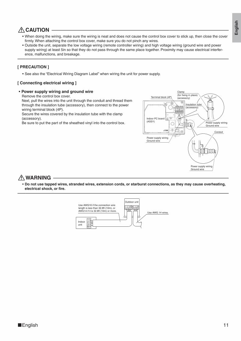
[ Connecting electrical wiring ]
•Power supply wiring and ground wireRemovethecontrolboxcover.Next,pullthewiresintotheunitthroughtheconduitandthreadthemthroughtheinsulationtube(accessory),thenconnecttothepowerwiringterminalblock(4P).Securethewirescoveredbytheinsulationtubewiththeclamp(accessory).Besuretoputthepartofthesheathedvinylintothecontrolbox.
Terminal block (4P)
Conduit
Power supply wiringGround wire
Indoor PC board(ASSY)
Clamp (for fixing in place) (accessory)
Power supply wiringGround wire
Power supply wiringGround wire
Insulation tube (accessory)
WARNING•Do not use tapped wires, stranded wires, extension cords, or starburst connections, as they may cause overheating,
electrical shock, or fire.
123
1 2 3 GRL1L2Use AWG16 if the connection wire length is less than 32.8ft (10m), or AWG14 if it is 32.8ft (10m) or more.
Outdoor unit
Indoor unit
Use AWG 14 wires.
01_EN_3P297301-3C.indd 11 10/26/2012 11:27:27 AM

12 ■English
Trial Operation and Testing1. Trial operation and testing
(1)Measurethesupplyvoltageandmakesurethatitfallsinthespecifiedrange.(2)Trialoperationshouldbecarriedoutineithercoolingorheatingmode.
(1) Press ON/OFF button to turn on the system.(2) Simultaneously press center of TEMP button and MODE button.(3) Press MODE button twice. (“ ” will appear on the display to indicate that Trial Operation mode is selected.)(4) Trial operation mode terminates in approx. 30 minutes and switches into normal mode. To quit the trial operation, press
ON/OFF button.
Trial operation from remote controller
Incoolingmode,selectthelowestprogrammabletemperature;inheatingmode,selectthehighestprogrammabletempera-ture.•Trialoperationmaybedisabledineithermodedependingontheroomtemperature.•Aftertrialoperationiscomplete,setthetemperaturetoanormallevel(79°F(26°C)to82°F(28°C)incoolingmode,68°F(20°C)to75°F(24°C)inheatingmode).
•Forprotection,thesystemdisablesrestartoperationfor3minutesafteritisturnedoff.
(3)CarryoutthetestoperationinaccordancewiththeOperationManualtoensurethatallfunctionsandparts,areworkingproperly.*Theairconditionerrequiresasmallamountofpowerinitsstandbymode.Ifthesystemisnottobeusedforsometimeafterinstallation,shutoffthecircuitbreakertoeliminateunnecessarypowerconsumption.
*Ifthecircuitbreakertripstoshutoffthepowertotheairconditioner,thesystemwillrestoretheoriginaloperationmodewhenthecircuitbreakeristurnedonagain.
2. Test items
Testitems Symptom(diagnosticdisplayonRC) Check
Indoorandoutdoorunitsareinstalledproperlyonsolidbases. Fall,vibration,noise
Norefrigerantgasleaks.Incompletecooling/heatingfunction
Refrigerantgasandliquidpipesandindoordrainhoseextensionarethermallyinsulated.
Waterleakage
Drainpipeisproperlyinstalled. Waterleakage
Systemisproperlygrounded. Electricalleakage
Thespecifiedwiresareusedforinterconnectingwireconnections. Inoperativeorburndamage
Indoororoutdoorunit’sairinletordischargehasclearpathofair.Shut-offvalvesareopened.
Incompletecooling/heatingfunction
Indoorunitproperlyreceivesremotecontrollercommands. Inoperative
01_EN_3P297301-3C.indd 12 10/26/2012 11:27:27 AM
Two-dimensional bar code is a code for manufacturing.
3P297301-3C M11B121B (1210) HT
00_CV_3P297301-3C.indd 2 10/26/2012 11:23:57 AM