Embed Size (px)
Citation preview

Installation Manual
Schlumberger Dispenser Interface Kits
Manual Number 577013-487, Revision D
For Veeder-Root TLS-350R Systems
Current Loop Dispenser Interface Module (DIM)Part No. 330404-001 and Part No. 84749X-400
SAM Dispenser Interface Module (DIM) 848731-XXXPart No. 330404-002 and Part No. 84749X-401
MicroMax with Allied DIM Installation Kit No. 848711-XXX
Pro Series with XPIC/SAM DIM Installation Kit No. 848731-XXX
MicroMax with XPIC/Tokheim DHC DIM Installation Kit No. 848751-XXX
SAM Dispenser Interface Module (DIM) 848731-XXXPart No. 330404-002 and Part No. 84749X-401
Notice
Veeder-Root makes no warranty of any kind with regard to this publication, including, but not limited to, the implied warranties of merchantability and fitness for a particular purpose.
Veeder-Root shall not be liable for errors contained herein or for incidental or consequential damages in connection with the furnishing, performance, or use of this publication.
This publication contains proprietary information which is protected by copyright. All rights reserved. No part of this publication may be photocopied, reproduced, or translated to another language without the prior written consent of Veeder-Root.
The information contained in this publication is subject to change without notice.
FCC Information
This equipment complies with the requirements in Part 15 of the FCC rules for a Class A computing device. Operation of this equipment in a residential area may cause unacceptable interference to radio and TV reception requiring the operator to take whatever steps are necessary to correct the interference.
Veeder-Root 1997. All rights reserved.
5770
13-3
49, R
evis
ion
D
Reader Comment Card
Please take a moment to review this manual. Your comments will help us improve our manuals. Thank you!
Please circle one number for each. Strongly Agree Agree Neutral Disagree Strongly
Disagree
This manual contains the information I need. 5 4 3 2 1
This manual is well organized. 5 4 3 2 1
Layout and format of the manual make it easy to use.
5 4 3 2 1
Instructions are easy to understand. 5 4 3 2 1
Instructions are complete. 5 4 3 2 1
Illustrations are clear and helpful. 5 4 3 2 1
There are enough illustrations. 5 4 3 2 1
Manual meets my expectations. 5 4 3 2 1
Things I would like to see added:
Write additional comments. Please be specific.
Manual Name Manual Title
Your Name Your Title
Company
Address
City/State/Zip Phone
Mail to:Technical Publications Dept.
Veeder-RootP.O. Box 2003
Simsbury, CT 06070-2003Or fax to:
(860) 651-2719Attn: Technical Publications Dept.
5770
13-3
39, R
evis
ion
B

i
5770
13-3
40, R
evis
ion
F
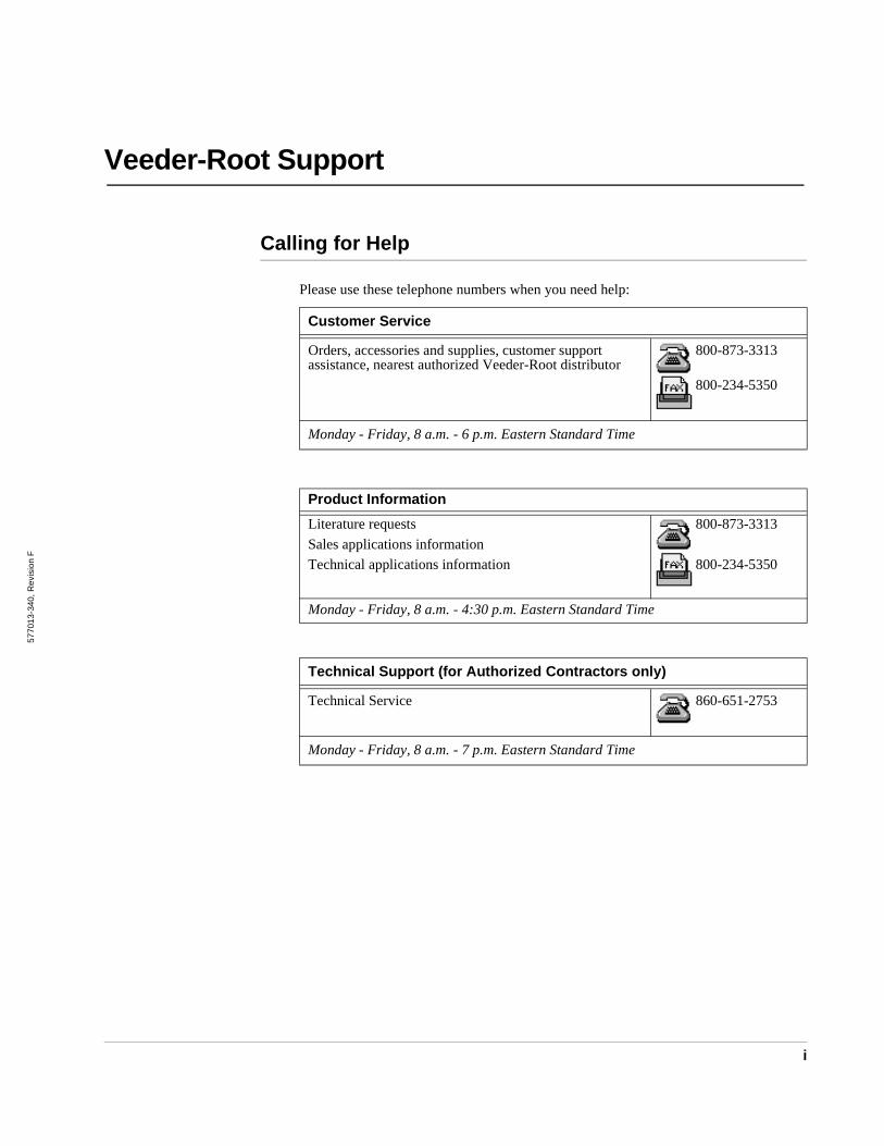
Veeder-Root Support
Calling for Help
Please use these telephone numbers when you need help:
Customer Service
Orders, accessories and supplies, customer support assistance, nearest authorized Veeder-Root distributor
800-873-3313
800-234-5350
Monday - Friday, 8 a.m. - 6 p.m. Eastern Standard Time
Product Information
Literature requests
Sales applications information
Technical applications information
800-873-3313
800-234-5350
Monday - Friday, 8 a.m. - 4:30 p.m. Eastern Standard Time
Technical Support (for Authorized Contractors only)
Technical Service 860-651-2753
Monday - Friday, 8 a.m. - 7 p.m. Eastern Standard Time

ii
iii
Veeder-Root SupportCalling for Help ...............................................................................................i
IntroductionGeneral ..........................................................................................................1Dispenser Interface Modules (DIMs) .............................................................1DIM Installation Kits .......................................................................................1Safety Symbols ..............................................................................................2Safety Warnings .............................................................................................2
DIM and CAB InstallationRequirements .................................................................................................3Dispenser Interface Module (DIM) Installation ...............................................3Mounting the Current Loop and RS-232 CAB ................................................5
MicroMax/Pro Series/SAM Generic Point-Of-Sale (POS)System Requirements ....................................................................................9System Limitations .......................................................................................10MicroMax/Allied Hardware Requirements ....................................................10Wiring New Installations ...............................................................................10Wiring Existing Installations .........................................................................12
Warranty Conditions and Limitations of LiabilityLimitations Of Liability ..................................................................................19Inspection .....................................................................................................19Limitation of Remedy and Warranty .............................................................19Limitation of Damages .................................................................................20Limitation of Actions .....................................................................................20Collateral Promises ......................................................................................20Interpretation ................................................................................................20
Glossary .................................................................................. Glossary-1
Contents
Contents
iv
Figures
Figure 1. ECPU Board Battery Switch ON (SW1).................................. 4Figure 2. DIM Card Installation .............................................................. 5Figure 3. Dimensions of Current Loop Cable Adapter Box.................... 6Figure 4. Dimensions of RS-232 Cable Adapter Box............................. 7Figure 5. MicroMax POS with Allied Station Site Controller Box
Current Loop Interface.......................................................... 11Figure 6. MicroMax POS with Allied Protocol Box Current Loop
Interface ................................................................................ 13Figure 7. Pro Series or MicroMax POS with SAM or XPIC Controller
Box and RS-232 Cable Adapter Box Interface ..................... 15Figure 8. MicroMax POS with Tokheim DHC Controller Box and
RS-232 Cable Adapter Box Interface ................................... 17Figure 9. Verifone with SAM and RS-232 Cable Adapter Box
Interface ................................................................................ 18
Introduction General
1
Introduction
General
This manual contains installation procedures for the Schlumberger Current Loop Dispenser Interface Module (DIM), SAM (Schlumberger Access Module) Dispenser Interface Module (DIM), MicroMax with Allied DIM Installation Kit, Pro Series with XPIC DIM Installation Kit or SAM DIM Installation Kit, and MicroMax with XPIC DIM Installation Kit or Tokheim DHC DIM Installation Kit.
For additional information regarding DIMs, refer to the Veeder-Root TLS-350R System Setup manual. If this is a new installation or if site preparation is necessary, refer to the Veeder-Root TLS-350R Site Preparation and Installation Instructions manual, or contact your Veeder-Root representative for assistance.
Dispenser Interface Modules (DIMs)
DIMs provide an interface for the TLS-350R to certain Point-of-Sale (POS) systems. This manual describes the operation, installation, and set-up of the Current Loop DIM.
The DIM allows the TLS-350R console to gather relevant dispensing information, including how much product has been dispensed from each fueling station.
DIM Installation Kits
DIM Installation Kits provide hardware and cable to interconnect the TLS-350R and DIM to the POS systems. The installation kits vary for each DIM, and include all adapter boxes and cables for installation. Different length cables are available.
Safety Symbols Introduction
2
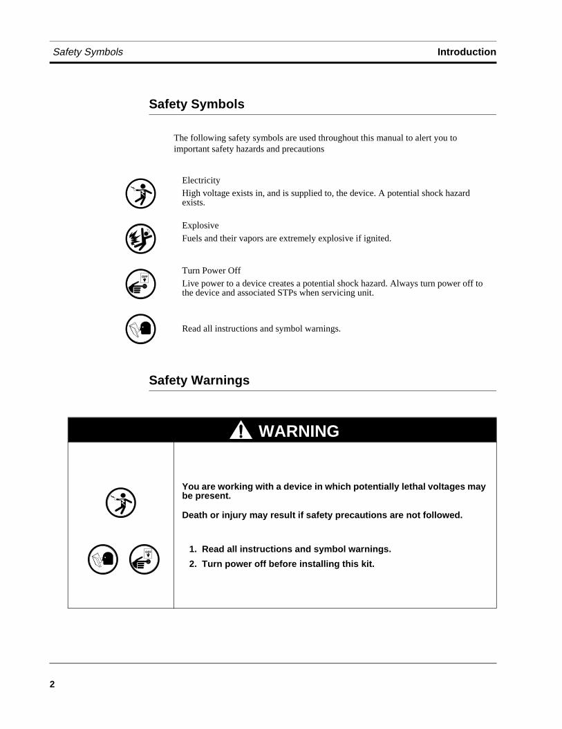
Safety Symbols
The following safety symbols are used throughout this manual to alert you to important safety hazards and precautions
Safety Warnings
Electricity
High voltage exists in, and is supplied to, the device. A potential shock hazard exists.
Explosive
Fuels and their vapors are extremely explosive if ignited.
Turn Power Off
Live power to a device creates a potential shock hazard. Always turn power off to the device and associated STPs when servicing unit.
Read all instructions and symbol warnings.
OFF
WARNING
You are working with a device in which potentially lethal voltages may be present.
Death or injury may result if safety precautions are not followed.
1. Read all instructions and symbol warnings.
2. Turn power off before installing this kit.
OFF
DIM and CAB Installation Requirements
3
DIM and CAB Installation
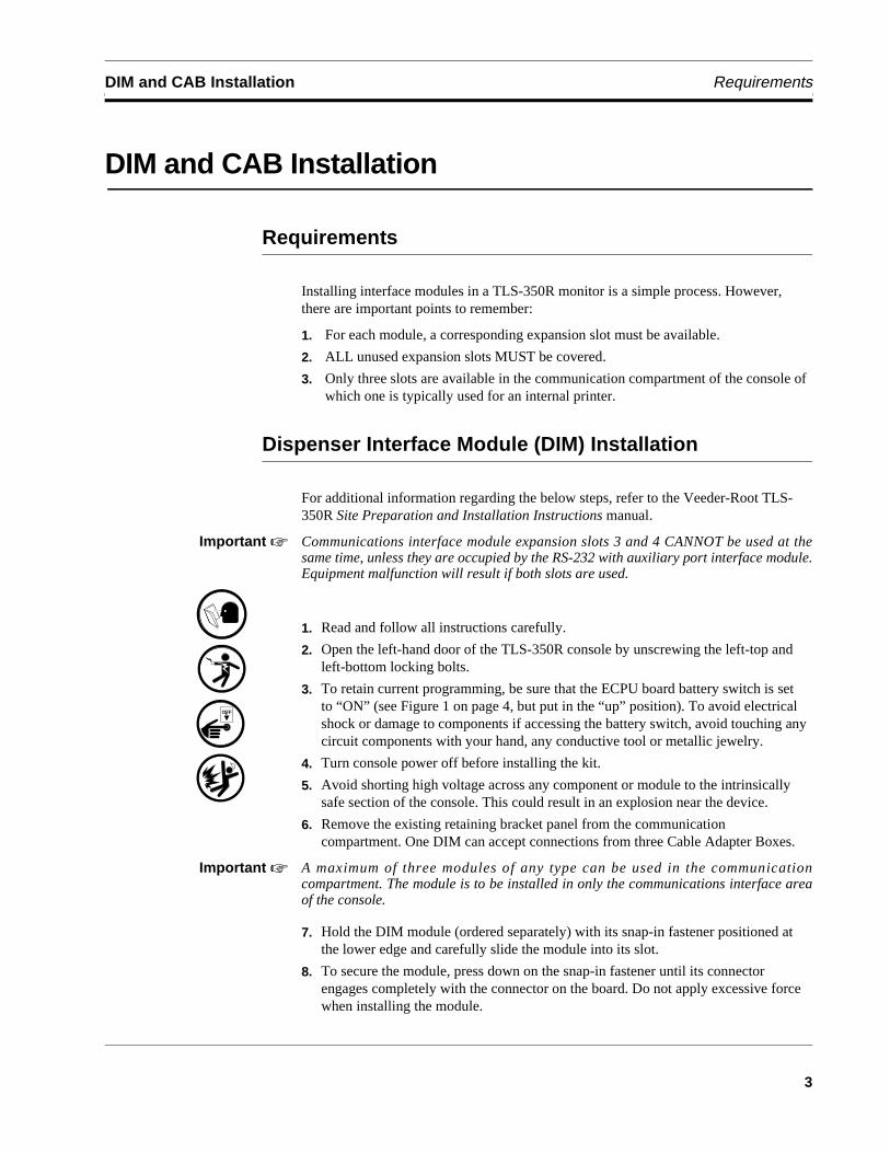
Requirements
Installing interface modules in a TLS-350R monitor is a simple process. However, there are important points to remember:
1. For each module, a corresponding expansion slot must be available.
2. ALL unused expansion slots MUST be covered.
3. Only three slots are available in the communication compartment of the console of which one is typically used for an internal printer.
Dispenser Interface Module (DIM) Installation
For additional information regarding the below steps, refer to the Veeder-Root TLS-350R Site Preparation and Installation Instructions manual.
Important ☞ Communications interface module expansion slots 3 and 4 CANNOT be used at thesame time, unless they are occupied by the RS-232 with auxiliary port interface module.Equipment malfunction will result if both slots are used.
1. Read and follow all instructions carefully.
2. Open the left-hand door of the TLS-350R console by unscrewing the left-top and left-bottom locking bolts.
3. To retain current programming, be sure that the ECPU board battery switch is set to “ON” (see Figure 1 on page 4, but put in the “up” position). To avoid electrical shock or damage to components if accessing the battery switch, avoid touching any circuit components with your hand, any conductive tool or metallic jewelry.
4. Turn console power off before installing the kit.
5. Avoid shorting high voltage across any component or module to the intrinsically safe section of the console. This could result in an explosion near the device.
6. Remove the existing retaining bracket panel from the communication compartment. One DIM can accept connections from three Cable Adapter Boxes.
Important ☞ A maximum of three modules of any type can be used in the communicationcompartment. The module is to be installed in only the communications interface areaof the console.
7. Hold the DIM module (ordered separately) with its snap-in fastener positioned at the lower edge and carefully slide the module into its slot.
8. To secure the module, press down on the snap-in fastener until its connector engages completely with the connector on the board. Do not apply excessive force when installing the module.
OFF
Dispenser Interface Module (DIM) Installation DIM and CAB Installation
4
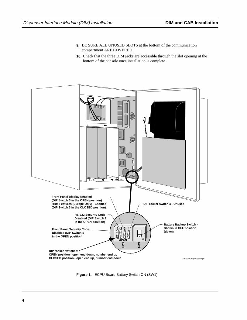
9. BE SURE ALL UNUSED SLOTS at the bottom of the communication compartment ARE COVERED!
10. Check that the three DIM jacks are accessible through the slot opening at the bottom of the console once installation is complete.
Figure 1. ECPU Board Battery Switch ON (SW1)
SW
2
SW
1
Front Panel Security Code Disabled (DIP Switch 1 in the OPEN position)
consoles\ecpubbsw.eps
RS-232 Security Code Disabled (DIP Switch 2in the OPEN position)
1 2 3 4Battery Backup Switch - Shown in OFF position(down)
OPEN
DIP rocker switches: OPEN position - open end down, number end upCLOSED position - open end up, number end down
DIP rocker switch 4 - Unused
Front Panel Display Enabled(DIP Switch 3 in the OPEN position)HRM Features (Europe Only) - Enabled (DIP Switch 3 in the CLOSED position)
DIM and CAB Installation Mounting the Current Loop and RS-232 CAB
5
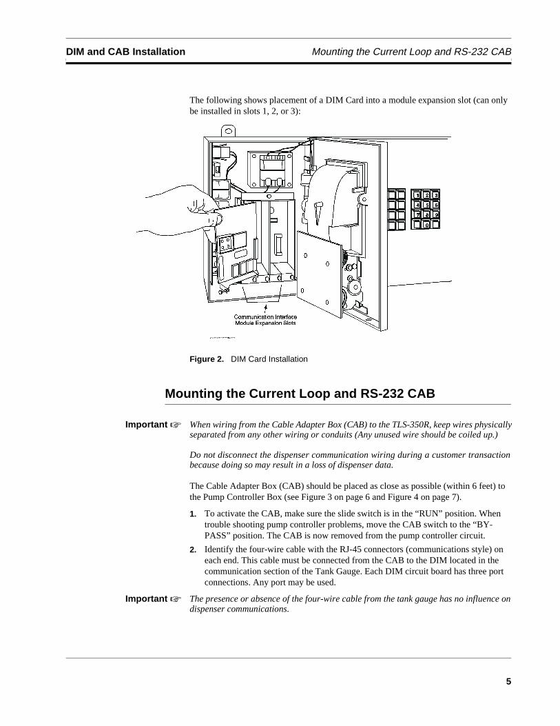
The following shows placement of a DIM Card into a module expansion slot (can only be installed in slots 1, 2, or 3):
Figure 2. DIM Card Installation
Mounting the Current Loop and RS-232 CAB
Important ☞ When wiring from the Cable Adapter Box (CAB) to the TLS-350R, keep wires physicallyseparated from any other wiring or conduits (Any unused wire should be coiled up.)
Do not disconnect the dispenser communication wiring during a customer transactionbecause doing so may result in a loss of dispenser data.
The Cable Adapter Box (CAB) should be placed as close as possible (within 6 feet) to the Pump Controller Box (see Figure 3 on page 6 and Figure 4 on page 7).
1. To activate the CAB, make sure the slide switch is in the “RUN” position. When trouble shooting pump controller problems, move the CAB switch to the “BY-PASS” position. The CAB is now removed from the pump controller circuit.
2. Identify the four-wire cable with the RJ-45 connectors (communications style) on each end. This cable must be connected from the CAB to the DIM located in the communication section of the Tank Gauge. Each DIM circuit board has three port connections. Any port may be used.
Important ☞ The presence or absence of the four-wire cable from the tank gauge has no influence ondispenser communications.
Mounting the Current Loop and RS-232 CAB DIM and CAB Installation
6
3. Mount the CAB using either the 3M “hook and loop” pads provided in the kit, or utilize the mounting ears on the CAB (see Figure 3 on page 6 and Figure 4 on page 7). Choose a surface that is clean, dry, and oil-free. For the 3M “hook and loop” pads, remove the backing paper from the back of the pad. Place the adhesive side on the surface and press firmly into position. The adhesive must be allowed to set for a minimum of one hour before attaching or removing the CAB.
Important ☞ The Cable Adapter Box can be mounted on any flat surface located indoors in a non-hazardous location.
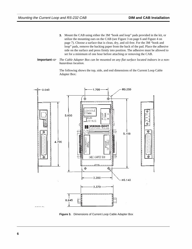
The following shows the top, side, and end dimensions of the Current Loop Cable Adapter Box:
Figure 3. Dimensions of Current Loop Cable Adapter Box
DIM and CAB Installation Mounting the Current Loop and RS-232 CAB
7
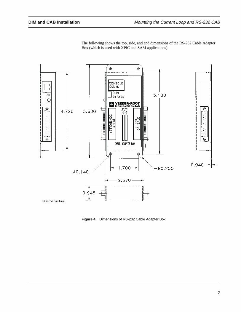
The following shows the top, side, and end dimensions of the RS-232 Cable Adapter Box (which is used with XPIC and SAM applications):
Figure 4. Dimensions of RS-232 Cable Adapter Box

Mounting the Current Loop and RS-232 CAB DIM and CAB Installation
8
MicroMax/Pro Series/SAM Generic Point-Of-Sale (POS) System Requirements
9
MicroMax/Pro Series/SAM Generic Point-Of-Sale (POS)
System Requirements
Veeder Root Hardware Requirements
The following equipment is required to interface to the Schlumberger MicroMax/Pro Series POS System:
❑ TLS-350R console with Business Inventory Reconciliation (BIR)
❑ One Schlumberger Current Loop Dispenser Interface Module (DIM) (For up to 32 fueling positions):Part No. 330404-001 when ordered with the consolePart No. 84749X-400 when ordered as an upgrade or replacementDIM Software Item No. 330435-001B (or higher)
❑ One Schlumberger SAM Dispenser Interface Module (DIM) (For up to 36 fueling positions):Part No. 330404-002 when ordered with the consolePart No. 84749X-401 when ordered as an upgrade or replacementDIM Software Item No. 331274-001
❑ One Schlumberger DIM Installation Kit: MicroMax/Allied Part No. 848711-XXXORPro Series/XPIC/SAM Part No. 848731-XXXORMicroMax/XPIC/DHC Part No. 848751-XXX
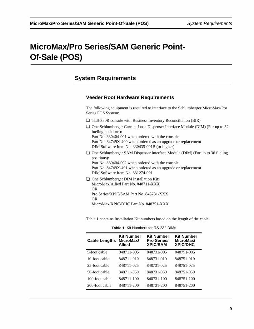
Table 1 contains Installation Kit numbers based on the length of the cable.
Table 1: Kit Numbers for RS-232 DIMs
Cable LengthsKit NumberMicroMax/Allied
Kit NumberPro Series/XPIC/SAM
Kit NumberMicroMax/XPIC/DHC
5-foot cable 848711-005 848731-005 848751-005
10-foot cable 848711-010 848731-010 848751-010
25-foot cable 848711-025 848731-025 848751-025
50-foot cable 848711-050 848731-050 848751-050
100-foot cable 848711-100 848731-100 848751-100
200-foot cable 848711-200 848731-200 848751-200
System Limitations MicroMax/Pro Series/SAM Generic Point-Of-Sale (POS)
10
Important ☞ The installation kit includes a Cable Adapter Box (CAB) and cable to the TLS-350R.The CAB should be installed as close as possible to the pump controller box. Select theshortest suitable cable, measuring from the CAB to the TLS-350R.
TLS-350R Software Requirements❑ System Software: 349511-109-A, or 309-A (or higher)
❑ Peripheral Controller Software: 002B (or higher)
❑ Parameter String: B1ESVG (when operating in the metric mode, the last “G” should be replaced with an “M”). Refer to the Veeder-Root TLS-350R System Setup manual for further information.
System Limitations
❑ Dispenses single product only; no blenders.
Important ☞ In-Dispenser credit card readers ARE supported by the Schlumberger DispenserInterface Module.
MicroMax/Allied Hardware Requirements
❑ An Allied Protocol Box (PCB) or an Allied Station Site Controller (SSC) Box.
❑ Schlumberger MicroMax Point-of-Sale (POS) console (other POS terminals are not supported).
Important ☞ Schlumberger, Gilbarco, Wayne, or Tokheim dispensers may be used.
Wiring New Installations
Using a Station Site Controller (SSC) Box
Important ☞ To insure proper operation of the tank gauge, the switch on the Cable Adapter Box(CAB) must be in the “RUN” position.
1. On channel 1 of the SSC Box, disconnect the communication cable coming from the POS terminal.
2. Connect the communication cable to the POS connector on the CAB.
3. Connect the 24-inch SSC cable supplied in this kit to the Pump Controller connector of the CAB and channel 1 of the SSC.
Important ☞ The 2-position plug connector is not used with the SSC.
MicroMax/Pro Series/SAM Generic Point-Of-Sale (POS) Wiring New Installations
11
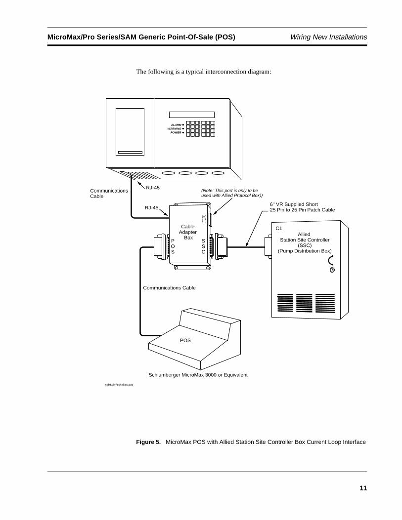
The following is a typical interconnection diagram:
Figure 5. MicroMax POS with Allied Station Site Controller Box Current Loop Interface
ALARMWARNING
POWER
Communications Cable
6" VR Supplied Short 25 Pin to 25 Pin Patch Cable
POS
cab&dim\schalssc.eps
(+)(–)
Communications Cable
Allied Station Site Controller
(SSC)(Pump Distribution Box)
Schlumberger MicroMax 3000 or Equivalent
(Note: This port is only to be used with Allied Protocol Box))
Cable Adapter
Box
RJ-45
RJ-45
POS
SSC
C1
Wiring Existing Installations MicroMax/Pro Series/SAM Generic Point-Of-Sale (POS)
12
Wiring Existing Installations
Using An Allied Protocol Box (PCB)
Important ☞ To insure proper operation of the tank gauge, the switch on the Cable Adapter Box(CAB) must be in the “RUN” position.
1. Complete all fueling transactions in process. Do not start any new transactions until the following connections are made.
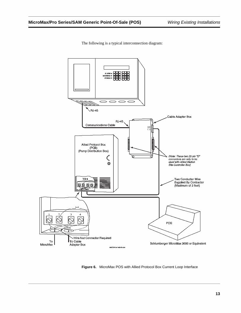
2. For Allied Protocol Boxes (PCBs), identify the communication cable coming from the Point-of-Sale (POS) terminal. This cable should connect to TB1 (terminal block) located inside the lower left hand corner of the PCB.
3. Remove the wire connected to position 2 of TB1. Connect this wire to contractor supplied two-wire cable, selecting the conductor which terminates at the “+CL” on the CAB. Attach using wire nut.
4. To complete the loop, connect the original POS wire to conductor of contractor supplied two-wire cable, terminating at “-CL” on the CAB to position 2 of TB1.
Important ☞ For applications using an Allied PCB, the two position plug connector on the bottom ofthe CAB must be used. The 24-inch controller cable and both of the DB-25 connectorsare not used.
MicroMax/Pro Series/SAM Generic Point-Of-Sale (POS) Wiring Existing Installations
13
The following is a typical interconnection diagram:
Figure 6. MicroMax POS with Allied Protocol Box Current Loop Interface
Wiring Existing Installations MicroMax/Pro Series/SAM Generic Point-Of-Sale (POS)
14
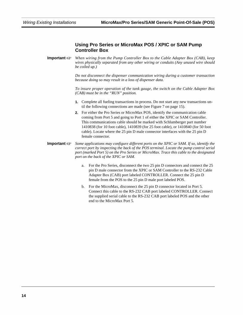
Using Pro Series or MicroMax POS / XPIC or SAM Pump Controller Box
Important ☞ When wiring from the Pump Controller Box to the Cable Adapter Box (CAB), keepwires physically separated from any other wiring or conduits (Any unused wire shouldbe coiled up.)
Do not disconnect the dispenser communication wiring during a customer transactionbecause doing so may result in a loss of dispenser data.
To insure proper operation of the tank gauge, the switch on the Cable Adapter Box(CAB) must be in the “RUN” position.
1. Complete all fueling transactions in process. Do not start any new transactions un-til the following connections are made (see Figure 7 on page 15).
2. For either the Pro Series or MicroMax POS, identify the communication cable coming from Port 5 and going to Port 1 of either the XPIC or SAM Controller. This communications cable should be marked with Schlumberger part number 1410838 (for 10 foot cable), 1410839 (for 25 foot cable), or 1410840 (for 50 foot cable). Locate where the 25 pin D male connector interfaces with the 25 pin D female connector.
Important ☞ Some applications may configure different ports on the XPIC or SAM. If so, identify thecorrect port by inspecting the back of the POS terminal. Locate the pump control serialport (marked Port 5) on the Pro Series or MicroMax. Trace this cable to the designatedport on the back of the XPIC or SAM.
a. For the Pro Series, disconnect the two 25 pin D connectors and connect the 25 pin D male connector from the XPIC or SAM Controller to the RS-232 Cable Adapter Box (CAB) port labeled CONTROLLER. Connect the 25 pin D female from the POS to the 25 pin D male port labeled POS.
b. For the MicroMax, disconnect the 25 pin D connector located in Port 5. Connect this cable to the RS-232 CAB port labeled CONTROLLER. Connect the supplied serial cable to the RS-232 CAB port labeled POS and the other end to the MicroMax Port 5.
MicroMax/Pro Series/SAM Generic Point-Of-Sale (POS) Wiring Existing Installations
15
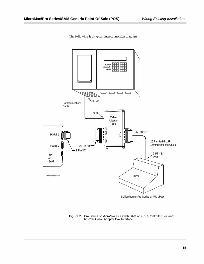
The following is a typical interconnection diagram:
Figure 7. Pro Series or MicroMax POS with SAM or XPIC Controller Box and RS-232 Cable Adapter Box Interface
ALARMWARNING
POWER
Communications Cable
POScab&dim\schxpic3.eps
Communications Cable
Cable Adapter
Box
RJ-45
RJ-45
PO
S
CO
NT
RO
LLE
R
XPICorSAM
PORT 1
PORT 2 25 Pin "D"
9 Pin "D"
25 Pin "D"
25 Pin Serial M/F
9 Pin "D"Port 5
Schlumberger Pro Series or MicroMax
Wiring Existing Installations MicroMax/Pro Series/SAM Generic Point-Of-Sale (POS)
16
Using MicroMax and Tokheim DHC Pump Controller Box
Important ☞ When wiring from the Pump Controller Box to the Cable Adapter Box (CAB), keepwires physically separated from any other wiring or conduits (Any unused wire shouldbe coiled up.)
Do not disconnect the dispenser communication wiring during a customer transactionbecause doing so may result in a loss of dispenser data.
To insure proper operation of the tank gauge, the switch on the Cable Adapter Box(CAB) must be in the “RUN” position.
1. Complete all fueling transactions in process. Do not start any new transactions un-til the following connections are made (see Figure 8 on page 17).
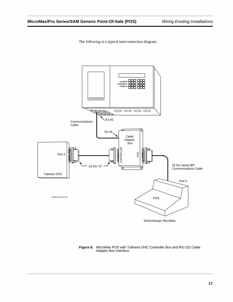
2. For MicroMax POS, identify the communication cable coming from Port 5 (of the MicroMax POS) and going to Port 2 of the Tokheim Controller.
3. Disconnect the 25 pin D connector located in Port 5 of the MicroMax. Connect this cable to the RS-232 CAB port labeled CONTROLLER. Connect the supplied serial cable to the RS-232 CAB port labeled POS and the other end to the MicroMax Port 5.
MicroMax/Pro Series/SAM Generic Point-Of-Sale (POS) Wiring Existing Installations
17
The following is a typical interconnection diagram:
Figure 8. MicroMax POS with Tokheim DHC Controller Box and RS-232 Cable Adapter Box Interface
ALARMWARNING
POWER
Communications Cable
POScab&dim\schxpic4.eps
25 Pin Serial M/F Communications Cable
Schlumberger MicroMax
Cable Adapter
Box
RJ-45
RJ-45
PO
S
CO
NTR
OLL
ER
25 Pin "D"
Tokheim DHC
Port 2
Port 5
Wiring Existing Installations MicroMax/Pro Series/SAM Generic Point-Of-Sale (POS)
18
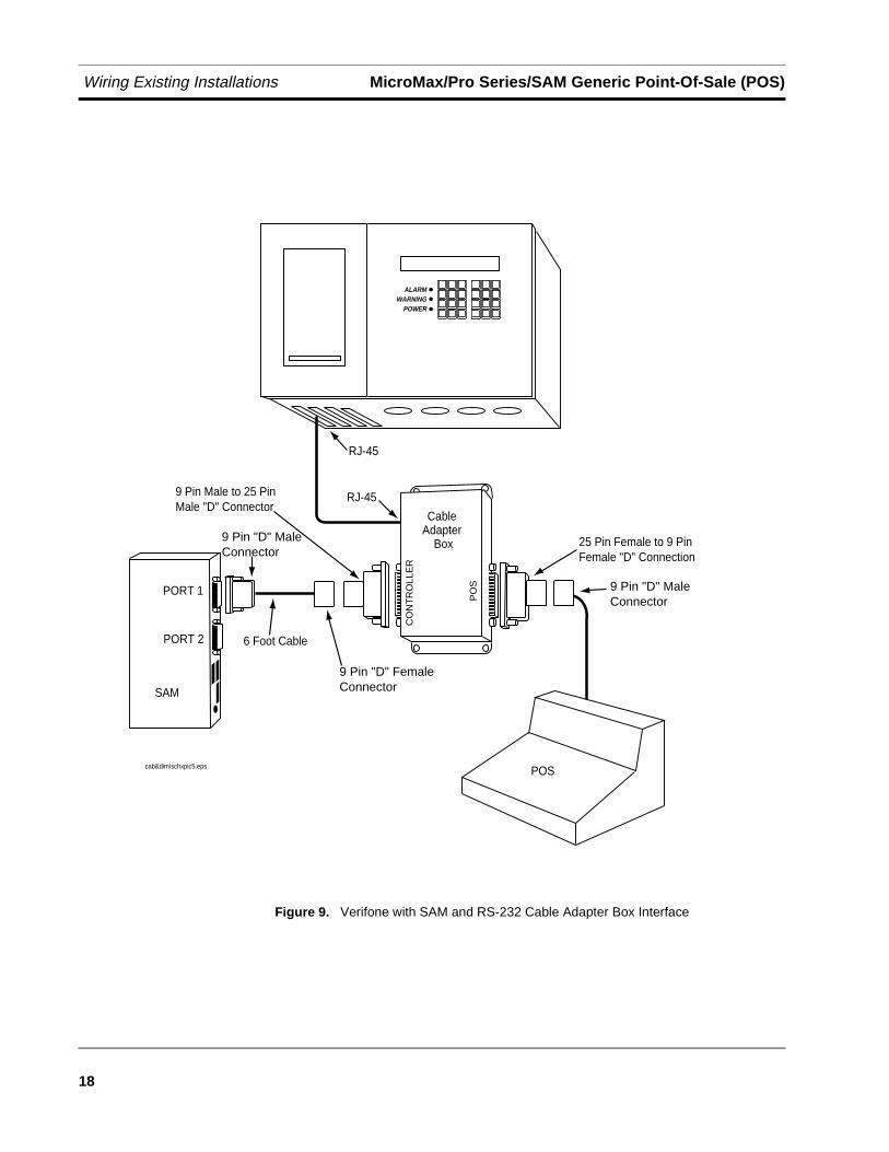
Figure 9. Verifone with SAM and RS-232 Cable Adapter Box Interface
ALARMWARNING
POWER
POScab&dim\schxpic5.eps
Cable Adapter
Box
RJ-45
RJ-45
PO
S
CO
NT
RO
LLE
R
SAM
PORT 1
PORT 2
25 Pin Female to 9 Pin Female "D" Connection
9 Pin Male to 25 Pin Male "D" Connector
9 Pin "D" Male Connector
9 Pin "D" FemaleConnector
6 Foot Cable
9 Pin "D" Male Connector
19
5770
13-3
51, R
evis
ion
B
Warranty Conditions and Limitations of Liability
Limitations Of Liability
We warrant that this product will be free from defects in materials and workmanship for a period of 1 year from the date of installation or 15 months from the date of invoice, whichever occurs first. We will repair or replace the product if it is returned to us, transportation prepaid, within the warranty period and is determined by us to be defective.
We shall not be responsible for any expenses incurred by the user.
This warranty applies only when the product is installed in accordance with Veeder-Root's specifications. This warranty will not apply to any product which has been subjected to misuse, negligence or accident; or misapplied; or used in violation of product manuals, instructions or warnings; or modified or repaired by unauthorized persons; or improperly installed.
Inspection
You shall inspect the product promptly after receipt and shall notify us at our Simsbury office in writing of any claims, including claims of breach of warranty, within 30 days after you discover or should have discovered the facts upon which the claim is based. Your failure to give written notice of a claim within the time period shall be deemed to be a waiver of such claim.
Limitation of Remedy and Warranty
The provisions of “Limitations Of Liability” on page 19 are our sole obligation and exclude all other remedies or warranties, express or implied, including warranties of MERCHANTABILITY and FITNESS FOR A PARTICULAR PURPOSE, whether or not purposes or specifications are described herein. We further disclaim any responsibility whatsoever to you or to any other person for injury to person or damage to or loss of property or value caused by any product which has been subjected to misuse, negligence, or accident; or misapplied; or used in violation of product manuals, instructions or warnings; or modified or repaired by unauthorized persons; or improperly installed.
Limitation of Damages Warranty Conditions and Limitations of Liability
20
5770
13-3
51, R
evis
ion
B
Limitation of Damages
Under no circumstances shall we be liable for any incidental, consequential or specific damages, losses or expenses arising from this contract or its performance or in connection with the use of, or inability to use, our product for any purpose whatsoever.
Limitation of Actions
No action regardless of form arising out of this contract may be commenced more than 1 year after the cause of action has accrued, except an action for nonpayment.
Collateral Promises
There are no representations, warranties, or conditions, express or implied, statutory or otherwise except those herein contained, and no agreement or waivers collateral hereto shall be binding on either party unless in writing and signed by you and accepted by us at our Simsbury office.
Interpretation
Rights and liabilities arising out of any contract with us shall be determined under the Uniform Commercial Code as enacted in Connecticut.
Glossary-21
ASC Authorized Service Contractor
AST Aboveground Storage Tank
auxiliary port Second serial port used for daisy chaining another console.
baud rate Transmission speed for serial communications.
Business Inventory Reconciliation (BIR)
The process of reconciling product dispensed with product received (deliveries), and product remaining in the tank.
Current Loop Dispenser Interface Module (CDIM)
Installs in a communication port of TLS-350R. More than one CDIM can be installed. May be installed with any combination of other DIM types. CDIM has three 4-pin phone jack con-nectors and three green LEDs inside, under cover. The green LEDs indicate data transmitted to DIM from an external device. CDIM cannot transmit to an external device. Connects via 4-wire cable to Adapter Box. Adapter box converts target communication format to RS-422 for-mat for CDIM. Adapter boxes are configured with two-wire flying leads, 25-pin “D” or nine-pin “D” T-cable connectors for various applications.
coefficient of thermal expansion
The amount of contraction or expansion that will occur with temperature changes in a specif-ic liquid.
communications Data transmissions between two or more pieces of equipment.
configuration Relative arrangement of parts of a system.
containment sump An enclosure used to contain submersible pumps and related piping to prevent the release of product into the environment.
Continuous Statistical Leak Detection (CSLD)
CSLD eliminates the need to shut down the station to run leak tests. Height data is collected during idle times and new tank information is used to produce highly accurate leak detection results.
data Information collected by the console.
default parameter setting
System set-up parameter that is pre-set by the factory.
diagnostics Indicators of the current conditions in the system.
differentiating See discriminating.
discriminating Also referred to as differentiating. A sensor that provides different alarms in the presence of hydrocarbon (fuel) leaks compared with water or other liquids.
dispenser Dispenses fuel through a nozzle, typically to a motor vehicle.
dispenser pan An enclosure used to contain dispenser piping to prevent release of product into the environ-ment.
double wall tank (DW tank)
A tank with a secondary wall to prevent leakage of product into the environment.
Glossary
Glossary
Glossary-22
Electronic Dispenser Interface Module (EDIM)
Installs in a communication port of TLS-350R. More than one EDIM can be installed. May be installed with any combination of other DIM types. EDIM has one 25-pin “D” connector outside of the port and a red and green LED inside, under cover: Red - DIM transmits to ex-ternal device; Green - external device transmits to DIM.
external output Field wiring locations where devices can be connected to the system, such as overfill alarms and warning lights.
float switch A sensing device in which a float is used to indicate the presence of liquid.
groundwater Water within the earth that supplies wells and springs.
hydrostatic sensor A sensor used to monitor liquid-filled double walled tanks, such as brine-filled tanks.
inventory How much product you have left.
interstitial Relates to the interstice, a space or gap between the walls of a double wall tank. Also referred to as annulus.
intrinsically safe A circuit in which any spark or thermal effect is incapable of causing ignition of combustible material.
magnetostriction The deformation of any substance due to the existence of magnetism.
Mechanical Dispenser Interface Module (MDIM)
Installs in the power side of TLS-350R. As many as eight MDIMs can be installed. MDIM has external eight-pin rectangular connector. May be installed with any combination of other DIM types. Connects to a maximum of four pulsers via intrinsically safe barriers which are mounted in any unused 1/2” or 1/4” hub of the dispenser junction box. Each barrier connects to a pulser with two wires that can be run anywhere inside the dispenser, without the need for conduit, because of the intrinsic safety provided by the barrier.
module An electronic component that plugs into the console to perform a special function.
probe A device used to obtain specific information in the tank and send the data to the console.
sensor A device that responds to a physical stimulus (such as water or gasoline).
tri-state sensors Tri-state sensors are piping sump sensors and steel and fiberglass tank interstitial sensors. The three conditions of this sensor are normal, fuel alarm, or sensor out.
Ullage Amount of empty space in tank
95% Ullage Amount of fuel required to fill tank to 95% capacity.
UST Underground Storage Tank
vapor A substance in the gaseous state as opposed to a liquid.
volumetric A method of detecting leaks in pressurized piping.

Sales Offices
Veeder-Root has offices around the world to serve you.
HeadquartersVeeder-Root Company125 Powder Forest DriveSimsbury, CT 06070-2003 U.S.A.(860) 651-2700 FAX: (860) 651-2719 TECH SUPPORT (860) 651-2753
EnglandVeeder-Root Environmental Systems LimitedHydrex House, Garden RoadRichmond, Surrey TW9 4NR ENGLAND44-181-392-1355
BrazilVeeder-Root do BRASILRua ado Benatti, 92Caixa Postal 834301051 Sao Paulo BRAZIL55-11-861-2155
GermanyVeeder-Root GmbHUhlandstrasse 49D-78554 Aldingen GERMANY49 (0)7424 89285
FranceVeeder-Root SARL ZI des Mardelles 94-106 rue Blaise Pascal93600 Aulnay-sous-Bois FRANCE33 (0)1 4879 5599
CanadaVeeder-Root Canada151 Superior Boulevard, Suite 24Mississauga, Ontario, L5T 2L1 CANADA905-670-2755
SingaporeVeeder-Root Singapore#2 Kallang Pudding Road#06-16 Mactech Industrial BuildingSINGAPORE 1334(65) 745-0368 FAX: (65) 745-0636
MexicoVeeder-Root MexicoPrado de las CameliasNo. 4483-4Praddos Tepeyac C.P. 45500Zapopan, Jal., MEXICO(52) 36-47-3750
577013-487, Revision D
5770
13-3
42, R
evis
ion
C