Embed Size (px)
Citation preview

www.furuno.co.jp
Installation Manual UAIS TRANSPONDER
FA-150
SAFETY INSTRUCTIONS.................................................................................................................... i
SYSTEM CONFIGURATIONS............................................................................................................. ii
EQUIPMENT LIST.............................................................................................................................. iii
1. MOUNTING.....................................................................................................................................1 1.1 Antenna Units ..........................................................................................................................1 1.2 Monitor Unit .............................................................................................................................8 1.3 UAIS Transponder .................................................................................................................10 1.4 Power Supply (option)............................................................................................................ 11 1.5 Pilot Plug (option) .................................................................................................................. 11
2. WIRING .........................................................................................................................................12 2.1 Connection.............................................................................................................................12 2.2 Changing Ship’s Mains Specifications ...................................................................................17
3. SETTING AND ADJUSTMENT......................................................................................................18 3.1 Stting MMSI, IMO No., Name and Cell Sign ..........................................................................18 3.2 Setting GPS Antenna Position ...............................................................................................20 3.3 Setting Ship Type...................................................................................................................21 3.4 Setting I/O Port ......................................................................................................................21
4. ATTACHING LAN KIT (OPTION) ...................................................................................................25
5. IEC 61162-1/2 DATA SENTENCES ...............................................................................................28
PACKING LISTS.............................................................................................................................. A-1
OUTLINE DRAWINGS .................................................................................................................... D-1
INTERCONNECTION DIAGRAM.................................................................................................... S-1

The paper used in this manualis elemental chlorine free.
・FURUNO Authorized Distributor/Dealer
9-52 Ashihara-cho,Nishinomiya, 662-8580, JAPAN
Telephone : +81-(0)798-65-2111
Fax : +81-(0)798-65-4200
A : NOV 2004.Printed in JapanAll rights reserved.
D : JUN . 11, 2008Pub. No. IME-44310-D
*00015008313**00015008313*(TATA ) FA-150*00015008313**00015008313** 0 0 0 1 5 0 0 8 3 1 3 *

i
SAFETY INSTRUCTIONS
WARNING
Turn off the power at the switchboardbefore beginning the installation.
Fire or electrical shock can result if thepower is left on.
Do not install the equipment where itmay get wet from rain or water splash.
Water in the equipment can result in fire,electrical shock or damage the equipment.
Be sure that the power supply iscompatible with the voltage rating ofthe equipment.
Connection of an incorrect power supplycan cause fire or damage the equipment. The voltage rating of the equipment appearson the label above the power connector.
ELECTRICAL SHOCK HAZARDDo not open the equipmentunless totally familiar withelectrical circuits andservice manual.
Only qualified personnelshould work inside theequipment.
CAUTIONObserve the following compass safedistances to prevent interference to amagnetic compass:
Standardcompass
Steeringcompass
FA-1501
FA-1502
GVA-100 0.3 m 0.3 m
DB-1 0.3 m 0.3 m
PR-240 0.9m 0.6 m
Attach securely protectiveearth to the ship's body.
The protective earth is required to the power supply to prevent electrical shock.
UAIS Transponder
Monitor unit
1.2 m 0.8 m
0.45 m 0.3 m

ii
SYSTEM CONFIGURATION
: Standard
: Option
GPS/VHFcombined antennaGVA-100
GPS antennaGSC-001GPA-017S
Distributor unitDB-1
VHF antenna
Power supplyPR-240
100-115/200-230 VAC1φ, 50/60Hz 12-24 VDC
: Local supply
Either
24 VDC
MONITOR UNITFA-1502
12-24 VDC
UAIS TRANSPONDERFA-1501
External display, NAVNET2, Pilot plug unitSensor
PC, BEACON RECEIVERAlarm system
UNIVERSAL AIS
STATUSNAV
FA-150 PWR
DISP DIM
MENU ENT
LAN
Category of the units
GSC-001 Exposed to the weather GPA-017S Exposed to the weather GVA-100 Exposed to the weather FA-1501 Protected from the weather FA-1502 Protected from the weather DB-1 Protected from the weather PR-240 Protected from the weather

iii
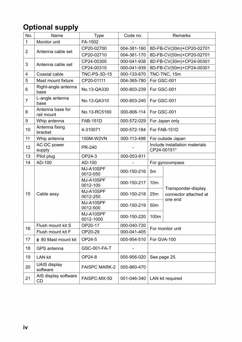
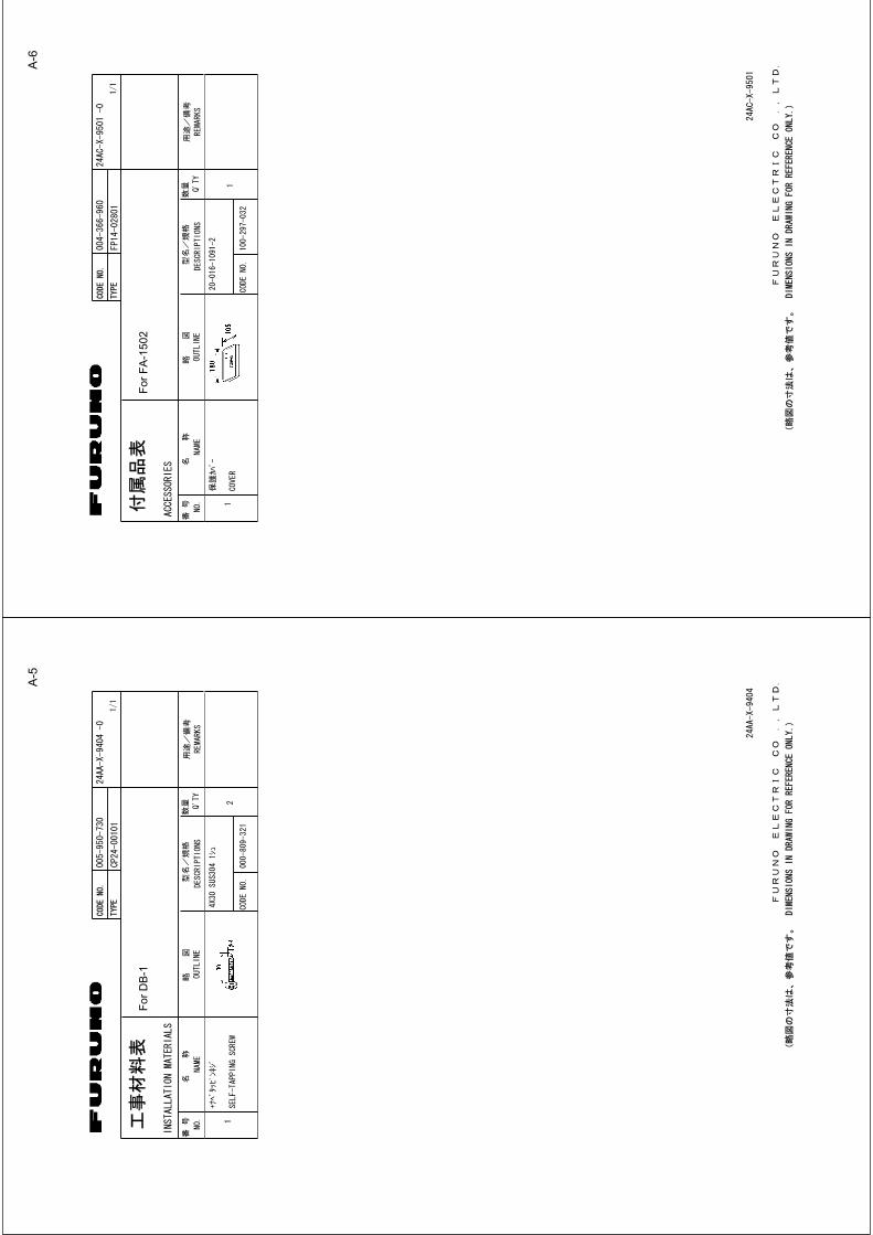
EQUIPMENT LISTS Standard supply No. Name Type Code no. Qty Remarks 1 UAIS Transponder FA-1501 - 1 2 Monitor Unit FA-1502 - 1
GSC-001 -GPS Antenna GPA-017S -3
GPS/VHF Combined GVA-100 -1 Select one.
MJ-A10SPF0012-050 000-150-216 1 Cable for FA-1501CP24-00501 005-955-550 For FA-1501
CP24-00400 000-041-980 1
For FA-1502 CP14-06001 & Cable MJ-A3SPF0013-035
CP24-00101 005-950-730 1 For DB-1 CP24-00141 005-952-330 1 For GVA-100
4 Installation Materials
CP24-00502 005-955-560 1 For GPA-017S/ GSC-001
5 Accessories FP14-02801 004-366-960 1 For FA-15026 Spare Parts SP24-00101 - 1 For FA-1502
iv
Optional supply No. Name Type Code no. Remarks 1 Monitor unit FA-1502 -
CP20-02700 004-381-160 8D-FB-CV(30m)+CP20-02701 2 Antenna cable set
CP20-02710 004-381-170 8D-FB-CV(50m)+CP20-02701 CP24-00300 000-041-938 8D-FB-CV(30m)+CP24-00301
3 Antenna cable set CP24-00310 000-041-939 8D-FB-CV(50m)+CP24-00301
4 Coaxial cable TNC-PS-3D-15 000-133-670 TNC-TNC, 15m 5 Mast mount fixture CP20-01111 004-365-780 For GSC-001
6 Right-angle antenna base No.13-QA330 000-803-239 For GSC-001
7 L-angle antenna base No.13-QA310 000-803-240 For GSC-001
8 Antenna base for rail mount No.13-RC5160 000-806-114 For GSC-001
9 Whip antenna FAB-151D 000-572-029 For Japan only
10 Antenna fixing bracket 4-310071 000-572-184 For FAB-151D
11 Whip antenna 150M-W2VN 000-113-498 For outside Japan
12 AC-DC power supply PR-240 - Include installation materials
CP24-00151* 13 Pilot plug OP24-3 000-053-911 14 AD-100 AD-100 - For gyrocompass
MJ-A10SPF 0012-050 000-150-216 5m
MJ-A10SPF 0012-100 000-150-217 10m
MJ-A10SPF 0012-250 000-150-218 25m
MJ-A10SPF 0012-500 000-150-219 50m
15 Cable assy.
MJ-A10SPF 0012-1000 000-150-220 100m
Transponder-display, connector attached at one end
Flush mount kit S OP20-17 000-040-72016
Flush mount kit F OP20-29 000-041-405For monitor unit
17 ɸ 80 Mast mount kit OP24-5 005-954-510 For GVA-100
18 GPS antenna GSC-001-FA-T -
19 LAN kit OP24-8 005-956-020 See page 25.
20 UAIS display software FAISPC MARK-2 005-860-470
21 AIS display software CD FAISPC-MX-50 001-046-340 LAN kit required

1
1. MOUNTING
NOTICEDo not apply paint, anti-corrosive sealant or contact sprayto coating or plastic parts of the equipment.
Those items contain organic solvents that can damage coatingand plastic parts, especially plastic connectors.
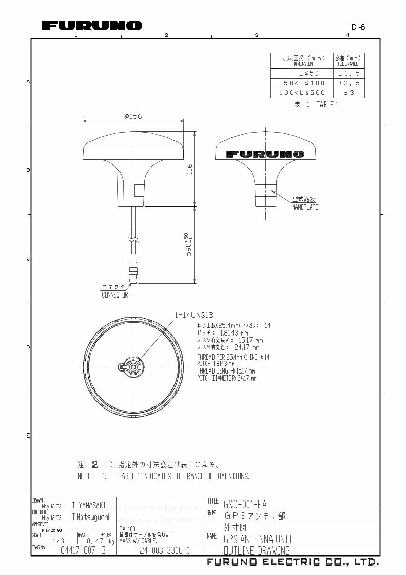
1.1 Antenna Units 1.1.1 GPS antenna unit Install the GPS antenna unit referring to the drawing on page D-5 or D-6 at the back of this manual. When selecting a mounting location for the antenna, keep in mind the following points. • Select a location out of the radar beam. The radar beam will obstruct or prevent
reception of the GPS satellite signal. • There should be no interfering object within the line-of-sight to the satellites. Objects
within line-of-sight to a satellite, for example, a mast, may block reception or prolong acquisition time.
• Mount the antenna unit as high as possible to keep it free of interfering objects and water spray, which can interrupt reception of GPS satellite signal if the water freezes.
Extending antenna cable
Three types of antenna cable extensions are optionally available. a) Antenna cable set CP20-02700
Antenna Unit
Antenna Cable
30m 1 m
Fabricate locally. (See next page.)N-P-8DFB
FA-1501
: ConnectorConversionCable Assy.NJ-JP-3DXV-1
TNCP-NJ
0.6m
Waterproofing connector
Wrap connector with vulcanizing tape and then vinyl tape. Bind the tape end with a cable-tie.
b) Antenna cable set CP20-02710 (8D-FB-CV, 50m)
Connect the cable the same as a) above. c) Cable type RG-10/UY (shipyard supply)
Note: The length of this cable should be less than 20 m to prevent signal loss. The coax. coupling cable assy.(type: NJ-TP+3DXV-1, code no. 000-123-809), coaxial connector(N-P-8DFB; supplied), vulcanizing tape and vinyl tape are required. Fabricate both ends of the cable as shown in the figure on the next page.
Waterproofing connector
2
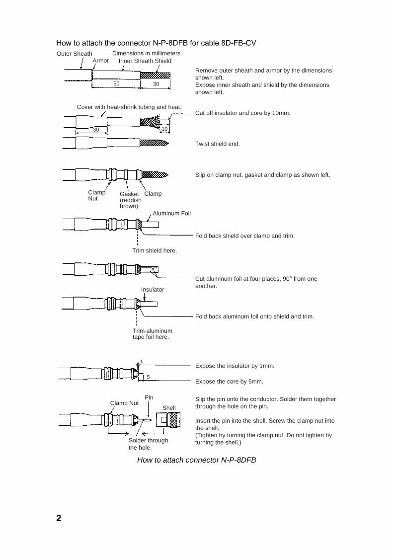
How to attach the connector N-P-8DFB for cable 8D-FB-CV Outer Sheath
ArmorDimensions in millimeters.
Inner Sheath Shield
Remove outer sheath and armor by the dimensions shown left.Expose inner sheath and shield by the dimensions shown left.
Cut off insulator and core by 10mm.
Twist shield end.
Slip on clamp nut, gasket and clamp as shown left.
Fold back shield over clamp and trim.
Cut aluminum foil at four places, 90° from one another.
Fold back aluminum foil onto shield and trim.
Expose the insulator by 1mm.
Expose the core by 5mm.
Slip the pin onto the conductor. Solder them together through the hole on the pin.
Insert the pin into the shell. Screw the clamp nut into the shell.(Tighten by turning the clamp nut. Do not tighten by turning the shell.)
Cover with heat-shrink tubing and heat.
30 10
ClampNut
Gasket(reddishbrown)
Clamp
Aluminum Foil
Trim shield here.
Trim aluminumtape foil here.
Insulator
1
5
Clamp NutPin
Shell
Solder throughthe hole.
50 30
How to attach connector N-P-8DFB

3
1.1.2 VHF antenna Location The location of the mandatory AIS VHF-antenna should be carefully considered. Digital communication is more sensitive than analog/voice communication to interference created by reflections in obstructions like masts and booms. It may be necessary to relocate the VHF radiotelephone antenna to minimize interference effects. To minimise interference effects, the following guidelines apply: • The AIS VHF antenna should be placed in an elevated position that is as free as
possible with a minimum of 0.5 meters in the horizontal direction from constructions made of conductive materials. The antenna should not be installed close to any large vertical obstruction. The objective for the AIS VHF antenna is to see the horizon freely through 360 degrees.
• The AIS VHF antenna should be installed safely away from interfering high-power energy sources like radar and other transmitting radio antennas, preferably at least 3 meters away from and out of the transmitting beam.
• There should not be more than one antenna on the same plane. The AIS VHF antenna should be mounted directly above or below the ship’s primary VHF radiotelephone antenna, with no horizontal separation and with a minimum of 2.8 meters vertical separation. If it is located on the same plane as other antennas, the distance apart should be at least 10 meters.
Cabling • The cable should be kept as short as possible to minimize signal attenuation.
Coaxial cables equal to or better than RG10U/Y are recommended. • All outdoor-installed connectors on coaxial cables should be fitted with preventive
isolation such as vulcanizing tape to protect against water penetration into the antenna cable.
• Coaxial cables should be installed in separate signal cable channels/tubes and at least 10 cm away from power supply cables. Crossing of cables should be done at right angles (90°). The minimum bend radius of the coaxial cable should be 5 times the cable's outer diameter.
• Install the VHF whip antenna referring to the outline drawing at the back of this manual. Separate this antenna from other VHF radiotelephone antennas as shown on the next page to prevent interference to the FA-150.

4
• When coaxial cable RG-10U/Y (shipyard supply) is used, attach the coaxial plug
M-P-7 (dockyard supply) as shown on the next page.
Horizontal separation distance
More than 10 m
More than 0.5 m
More than 2.8 m
Vertical separation distance
Other VHF whip antenna
Whip antenna for AIS (GPS/VHF combined antenna)

5
How to attach the plug M-P-7
Lay the coaxial cable and attach an M-type plug (if necessary) to the cable as follows. 1. Remove the sheath by 30 mm. 2. Bare 23 mm of the center conductor. Trim
braided shield by 5 mm and tin. 3. Slide coupling ring onto cable. 4. Screw the plug assembly on the cable. 5. Solder plug assembly to braided shield
through solder holes. Solder contact sleeve to conductor.
6. Screw coupling ring into plug assembly. 1.1.3 GPS/VHF combined antenna Install the combined antenna unit referring to the outline drawing. When selecting a mounting location for the antenna, keep in mind the following points. • Select a location out of the radar beam. The radar beam will obstruct or prevent
reception of the GPS satellite signal. • There should be no interfering object within the line-of-sight to the satellites. Objects
within line-of-sight to a satellite, for example, a mast, may block reception or prolong acquisition time.
• Mount the antenna unit as high as possible. Mounting it this way keeps it free of interfering objects and water spray, which can interrupt reception of GPS satellite signal if the water freezes.
• Also, refer to the antenna installation guidelines page 3.
Outdoor Indoor
N-P-8DFBN-P-8DFB
Distributor DB-1
GPS UAIS Transponder
VHF
RG-10U/Y
Installation overview of GPS/VHF combined antenna
Sheath30 mm
5 mm 2 mm
Conductor
InsulatorBraided shield
Plug assembly Contact sleeve
Cut conductor here.Solder both sides of hole.Coupling ring
6
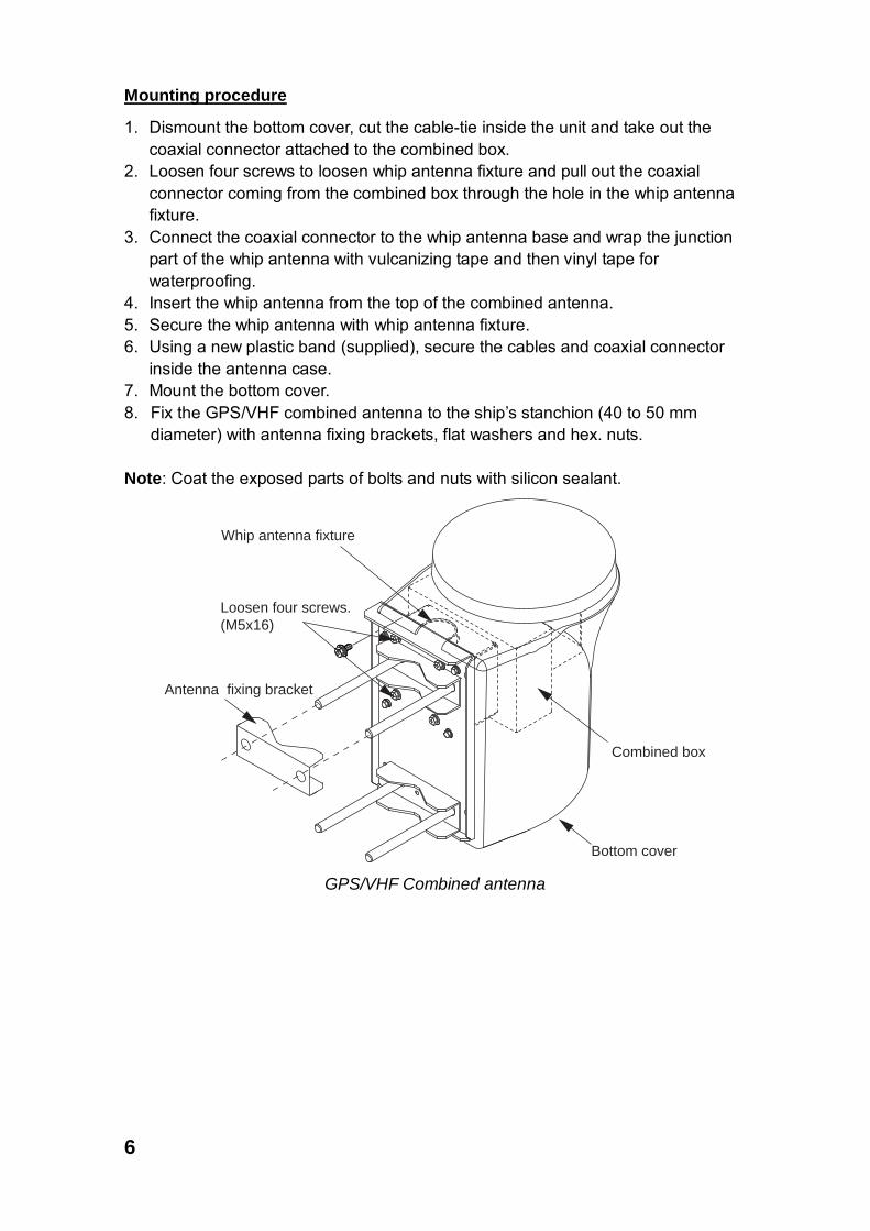
Mounting procedure
1. Dismount the bottom cover, cut the cable-tie inside the unit and take out the coaxial connector attached to the combined box.
2. Loosen four screws to loosen whip antenna fixture and pull out the coaxial connector coming from the combined box through the hole in the whip antenna fixture.
3. Connect the coaxial connector to the whip antenna base and wrap the junction part of the whip antenna with vulcanizing tape and then vinyl tape for waterproofing.
4. Insert the whip antenna from the top of the combined antenna. 5. Secure the whip antenna with whip antenna fixture. 6. Using a new plastic band (supplied), secure the cables and coaxial connector
inside the antenna case. 7. Mount the bottom cover. 8. Fix the GPS/VHF combined antenna to the ship’s stanchion (40 to 50 mm
diameter) with antenna fixing brackets, flat washers and hex. nuts. Note: Coat the exposed parts of bolts and nuts with silicon sealant.
Antenna fixing bracket
Loosen four screws.(M5x16)
Bottom cover
Combined box
Whip antenna fixture
GPS/VHF Combined antenna
7
Stanchion
The top of the stanchion comesinto contact with the flange.
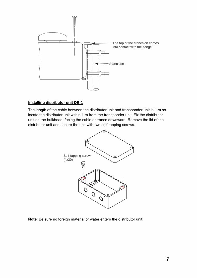
Installing distributor unit DB-1
The length of the cable between the distributor unit and transponder unit is 1 m so locate the distributor unit within 1 m from the transponder unit. Fix the distributor unit on the bulkhead, facing the cable entrance downward. Remove the lid of the distributor unit and secure the unit with two self-tapping screws.
Self-tapping screw(4x30)
Note: Be sure no foreign material or water enters the distributor unit.

8
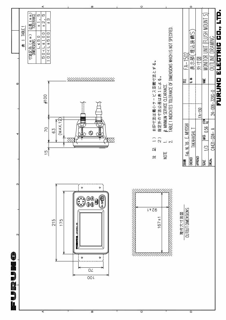
1.2 Monitor Unit The monitor unit can be installed on a desktop or flush mounted in a panel. Install it on the chart table or near the steering place, referring to the outline drawing. When selecting a mounting location for the monitor unit, keep the following in mind: • Keep the unit out of direct sunlight.
• The temperature and humidity should be moderate and stable. (Operating temperature range: -15°C to +55°C)
• Locate the unit away from exhaust pipes and vents.
• The mounting location should be well ventilated.
• Mount the unit where shock and vibration are minimal.
• Keep the unit away from electromagnetic field generating equipment such as motor, generator.
• For maintenance and checking purposes, leave sufficient space at the sides and rear of the unit and leave slack in cables. Refer to the outline drawing.
• A magnetic compass will be affected if the unit is placed too close to it. Observe the following compass safe distances to prevent disturbance to the magnetic compass:
Standard compass: 0.45 meters Steering compass: 0.3 meters
Desktop mounting
1. Fasten the hanger with four self-tapping screws (5x20). 2. Fasten the monitor unit to the hanger with two knobs.
Tabletop Overhead
Flush mounting
There are two types of flush mount kits, F type and S type. For details, see the outline diagrams at the back of this manual.

9
F type Use the optional flush mount kit OP20-29.
Name Type Code No. Qty
Cosmetic panel 20-016-1051 100-251-370-10 1
Self-tapping screw 5x20 000-162-609-10 4
Hexagon-head bolt M6x12 000-162-897-10 2
Spring washer M6 000-158-855-10 2
1. Prepare a cutout in the mounting location whose dimensions are 183 (W) x 92 (H) mm.
2. Attach the cosmetic panel (20-016-1051) to the unit with two hex head bolts (M6x12) and two spring washers (M6).
3. Fix the unit to the mounting location with four self-tapping screws (5x20).
S type Use the optional flush mount kit OP20-17.
.Name Type Code No. Qty
Fixing plate 20-007-2401 100-183-190-10 2
Hexagon-head bolt M6x12 000-162-897-10 2
Wing bolt M4x30 000-804-799 4
Wing nut M4 000-863-306 4
Spring washer M6 000-158-855-10 2
1. Prepare a cutout in the mounting location whose dimensions are 167 (W) x 92 (H) mm.
2. Insert the unit to the cutout. 3. Attach two fixing plates (20-007-2401) to the unit with two hex bolts (M6x12)
and two spring washers (M6). 4. Screw four wing bolts (M4x30) to wing nuts (M4). 5. Fasten the unit with four wing bolts and nuts.
10
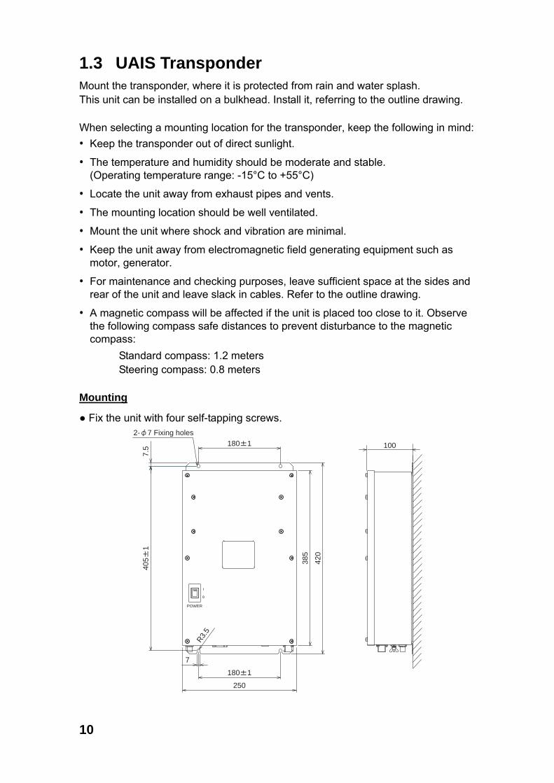
1.3 UAIS Transponder Mount the transponder, where it is protected from rain and water splash. This unit can be installed on a bulkhead. Install it, referring to the outline drawing. When selecting a mounting location for the transponder, keep the following in mind: • Keep the transponder out of direct sunlight.
• The temperature and humidity should be moderate and stable. (Operating temperature range: -15°C to +55°C)
• Locate the unit away from exhaust pipes and vents.
• The mounting location should be well ventilated.
• Mount the unit where shock and vibration are minimal.
• Keep the unit away from electromagnetic field generating equipment such as motor, generator.
• For maintenance and checking purposes, leave sufficient space at the sides and rear of the unit and leave slack in cables. Refer to the outline drawing.
• A magnetic compass will be affected if the unit is placed too close to it. Observe the following compass safe distances to prevent disturbance to the magnetic compass:
Standard compass: 1.2 meters Steering compass: 0.8 meters
Mounting
● Fix the unit with four self-tapping screws.
POWER
385
420
7
180 1
250
R3.5
405
17.5 180 1
2- 7 Fixing holes
100
11
1.4 Power Supply (option) When selecting a mounting location for the unit, keep the following in mind: • Keep the unit out away from areas subject to water splash. • Locate the unit away from exhaust pipes and vents. • The mounting location should be well ventilated. • Mount the unit where shock and vibration are minimal. • A magnetic compass will be affected if the unit is placed too close to it. Observe
the following compass safe distances to prevent disturbance to the magnetic compass:
Steering compass: 0.6 m Standard compass: 0.9 m
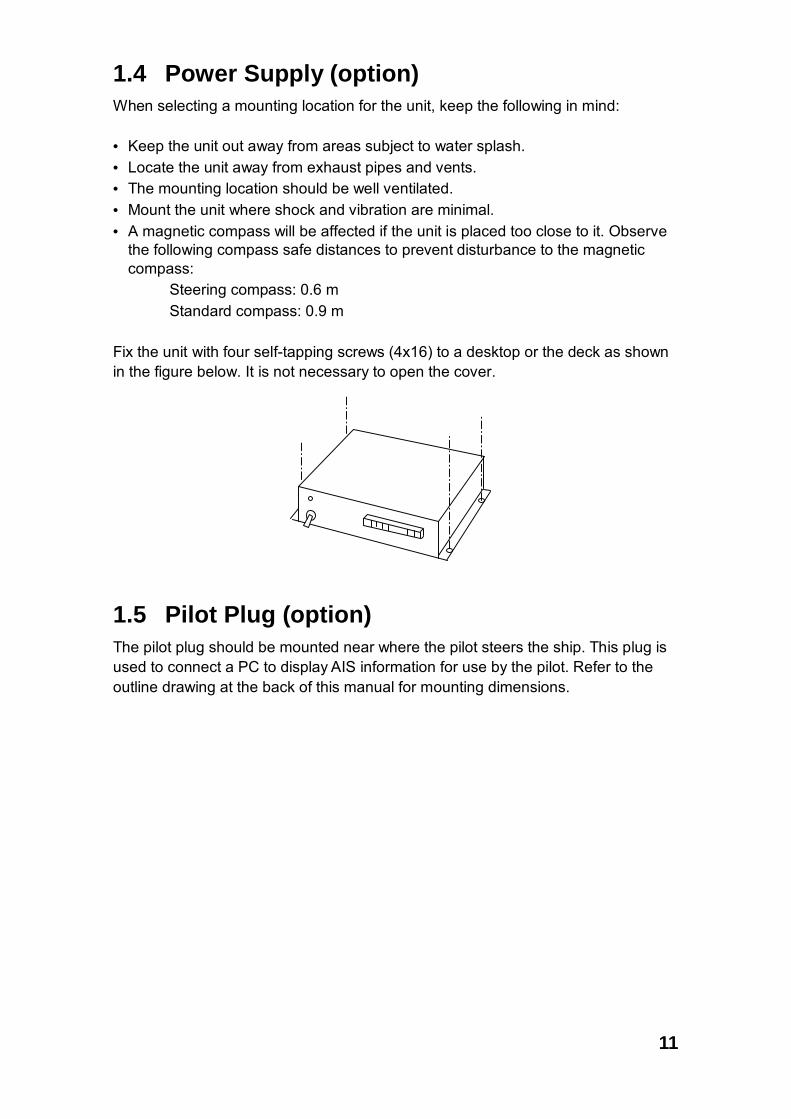
Fix the unit with four self-tapping screws (4x16) to a desktop or the deck as shown in the figure below. It is not necessary to open the cover.
1.5 Pilot Plug (option) The pilot plug should be mounted near where the pilot steers the ship. This plug is used to connect a PC to display AIS information for use by the pilot. Refer to the outline drawing at the back of this manual for mounting dimensions.

12
2. WIRING
2.1 Connection Connect the equipment, referring to the interconnection diagram at the back this manual.
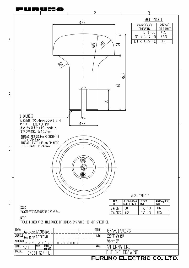
GPS AntennaGSC-001 or GPS-017S
PC
150M-W2VNor FAB-151D Either one
RG-10U/Y
RG-10U/YAttached to Distributor(approx. 1m)
Distributor unitDB-1
ACIN
DCIN
DCOUT
12-24 VDC(Connect to the alternative power source.)
100/110/115/200/220/230 VAC
Power SupplyPR-240
DP
YC
-2.5
GPS/VHF ConbinedAntenna GVA-100
8D-FB-CV, 30 m/50 m: OptionRG-10U/Y: Local supply
: Standard
: Option
: Local Supply
DPYC-1.5**
0.6 m
* **
0.8 m
: Ground is not required.
BREAKER6.3A
GPS ANT PC
VHF ANT
Other external device(See next page.)
GroundIV-2.0sq
Transponder unitFA-1501
*,**: See page 14.
12-24 VDC
Monitor unitFA-1502
IV-1.25sqMJ-A3SPF00133.5m
MJ-A10SPF00125/10/25/50/100m
IV-1.25sq
LAN
13
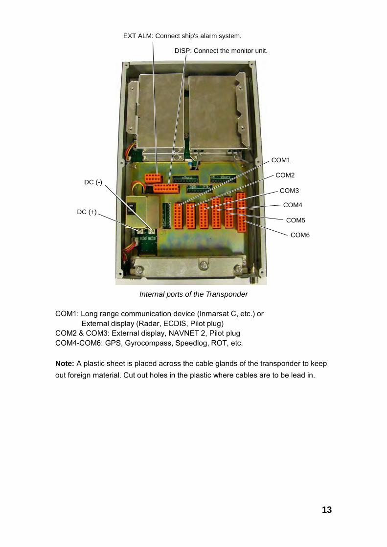
EXT ALM: Connect ship's alarm system.
DISP: Connect the monitor unit.
COM4
COM2
COM3
COM1
DC (-)
DC (+)
COM6
COM5
Internal ports of the Transponder
COM1: Long range communication device (Inmarsat C, etc.) or
External display (Radar, ECDIS, Pilot plug) COM2 & COM3: External display, NAVNET 2, Pilot plug COM4-COM6: GPS, Gyrocompass, Speedlog, ROT, etc. Note: A plastic sheet is placed across the cable glands of the transponder to keep out foreign material. Cut out holes in the plastic where cables are to be lead in.
14
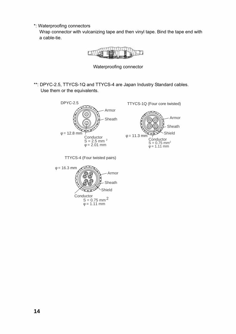
*: Waterproofing connectors Wrap connector with vulcanizing tape and then vinyl tape. Bind the tape end with a cable-tie.
Waterproofing connector
**: DPYC-2.5, TTYCS-1Q and TTYCS-4 are Japan Industry Standard cables. Use them or the equivalents.
ConductorS = 2.5 mmφ = 2.01 mm
2
DPYC-2.5
Armor
Sheath
φ = 12.8 mm
ConductorS = 0.75 mmφ = 1.11 mm
2
TTYCS-1Q (Four core twisted)
Armor
Shield
Sheath
φ = 11.3 mm
ConductorS = 0.75 mmφ = 1.11 mm
2
TTYCS-4 (Four twisted pairs)
Armor
Shield
Sheath
φ = 16.3 mm

15
Cable connection at transponder Fabrication of cables TTYCS-4 and TTYCS-1Q
L
6
Remove paint�by 50 mm.
Vinyl tape
Shield
45
50
Cut vinyl sheath.
Expose core and fold back�shield onto cable.
Lay in clamp�where paint�was removed.
L: Depends on equipment connected. Measure at the transponder.
Connection
Procedures1. Twist the cores.2. Press the terminal opener downward.3. Insert the wire to hole.4. Remove the terminal opener.5. Pull the wire to confirm that it is secure.
Terminal opener
Wiring for WAGO connector
WAGO connectorWire
Twist
Press downward.

16
Fabrication of power cable DPYC-2.5
40 mm: Peel paint.
Taping
Armor
50 mm
6 to7 mmVinyl sheath
Clamp here by cable clamp.

17
2.2 Changing Ship’s Mains Specifications The power supply PR-240 is shipped ready for connection to a 200-230 VAC ship’s mains. If the ship’s mains is 100 VAC – 115 VAC, change the tap connection and terminal board connection as below. Attach label supplied as accessories to the punch mark on the front panel according to the ship’s mains.
Ship’s mains Tap connection Terminal board connection #1 & #2
100-115 VAC SEL 115 V b
200-230 VAC SEL 230 V a
12345678
Heat sink
Tap connection (Pull out to remove)
Front
SEL115 V
SEL230 V
Top view (Cover removed)
1
2
3
100-115 VAC
1
2
3
200-230 VAC
Terminal board connection
(a) (b)
White
Black
White
Black
Punch mark
18
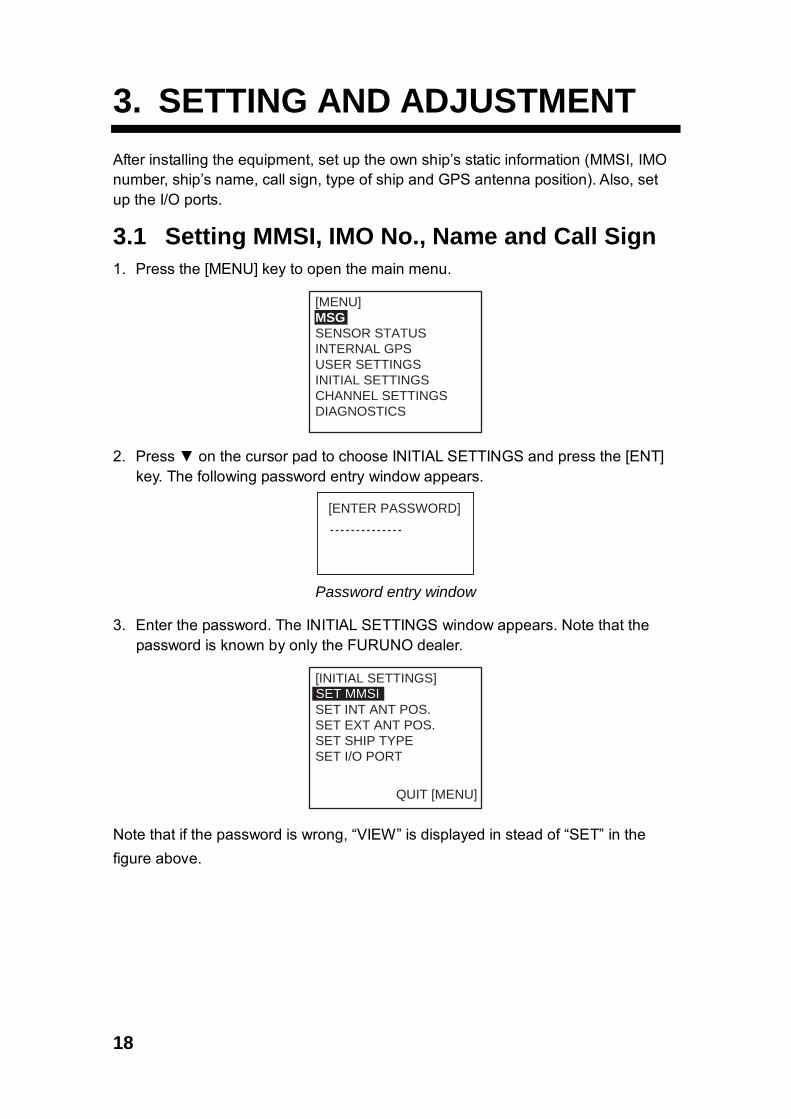
3. SETTING AND ADJUSTMENT After installing the equipment, set up the own ship’s static information (MMSI, IMO number, ship’s name, call sign, type of ship and GPS antenna position). Also, set up the I/O ports. 3.1 Setting MMSI, IMO No., Name and Call Sign 1. Press the [MENU] key to open the main menu.
[MENU]MSGSENSOR STATUSINTERNAL GPSUSER SETTINGSINITIAL SETTINGSCHANNEL SETTINGSDIAGNOSTICS
2. Press ▼ on the cursor pad to choose INITIAL SETTINGS and press the [ENT] key. The following password entry window appears.
[ENTER PASSWORD]
Password entry window
3. Enter the password. The INITIAL SETTINGS window appears. Note that the
password is known by only the FURUNO dealer.
[INITIAL SETTINGS]SET MMSISET INT ANT POS.SET EXT ANT POS.SET SHIP TYPESET I/O PORT
QUIT [MENU]
SET MMSI
Note that if the password is wrong, “VIEW” is displayed in stead of “SET” in the figure above.

19
4. SET MMSI is selected; press the [ENT] key to display the SET MMSI window.
NAME:
C. SIN:
MMSI: 000000000 IMO NO: 000000000
QUIT [MENU]
[SET MMSI]
SET MMSI window
5. MMSI is selected; press the [ENT] key. By using the cursor pad, enter ship’s
MMSI (Maritime Mobile Service Identity) in nine digits. To set value, press ▲ or ▼ key and to change the digit, press ◄ or ► key.
6. Press the [ENT] key and the IMO NO is selected. 7. Press the [ENT] key and enter ship’s IMO number in nine digits. If the IMO
number has 7 digits, enter “0” twice followed by IMO number. If the ship has no IMO number, enter nine zeroes.
8. Press the [ENT] key and the NAME is selected. 9. Press the [ENT] key and enter ship’s name, using up to 20 alphanumeric
characters. 10. Press the [ENT] key and the C. SIN is selected. 11. Press the [ENT] key and enter call sign, using up to seven alphanumeric
characters. 12. Press the [ENT] key. 13. Press the [MENU] key to save the settings. Note: If you enter incorrect data, do the procedure from step 1.

20
3.2 Setting GPS Antenna Position 1. Open the INITIAL SETTINGS window, referring to page 18. 2. Press ▲ or ▼ key to choose SET INT ANT POS. and press the [ENT] key.
[SET INT ANT POS.]
QUIT[MENU]
SET INT ANT POS. sub-menu(Data entry)
A: 0 mB: 0 mC: 0 mD: 0 m
A
B
C D
0
3. Press the [ENT] key again. 4. Enter distance for location “A” of FA-150 GPS antenna by using the cursor pad
and press the [ENT] key. A: Distance from bow to GPS antenna position, setting range: 0-511 m
5. Press the [ENT] key and enter distance for location B, C and D similar to how you did for "A" above.
B: Distance from stern to GPS antenna position, setting range: 0-511 m C: Distance from port to GPS antenna position, setting range: 0-63 m
D: Distance from starboard to GPS antenna position, the setting range: 0-63 m 6. Press the [MENU] key to return to the INITIAL SETTINGS menu. 7. Press ▲ or ▼ key to choose SET EXT ANT POS and press the [ENT] key. 8. Enter distance for location of an external GPS antenna (if connected) similar to
how you did for the internal GPS antenna. 9. Finally press the [MENU] key to save the settings.

21
3.3 Setting Ship Type 1. In the INITIAL SETTINGS window, press the ▲ or ▼ key to choose the SET
SHIP TYPE and press the [ENT] key.
[SET SHIP TYPE]TYPE NO : 0 *
* * * * TYPE DETAIL * * * *NOT AVAILABLE
2. Press the [ENT] key and set number for ship type by using ▲ or ▼ key,
referring to the table below. Table: Ship type
No. Ship type
1 Future use
2 WIG WIG: Wing in ground
3 Vessel
4 HSC HSC: High speed craft
5 Special craft
6 Passenger ships
7 Cargo ships
8 Tanker
9 Other type of ship
(For details, see “§1.5 Setting Up for Voyage” on the operator’s manual. 3. Press the [MENU] key to save the setting. 3.4 Setting I/O Port Setting COM port/PC port 1. In the INITIAL SETTINGS window, press ▲ or ▼ key to choose the SET I/O
PORT and press the [ENT] key.
[SET I/O PORT]COM1COM1SET PC PORTSET LAN PORT*SET PRIORITY
SET COM PORT
QUIT[MENU]
*: Only when LAN kit (option) attached.
SET I/O PORT menu
22
2. SET COM PORT is selected; press the [ENT] key. 3. Select an appropriate port among COM1, COM2, COM3, COM4, COM5 and
COM6. If you choose COM1 for example, do as follows. 4. Press the [ENT] key to display the COM1 setting window.
[SET COM1]MODE : LONG RANGESPEED: IEC 61162-2
QUIT [MENU]
5. Press the [ENT] key again to display the MODE setting window.
[SET COM1]MODE : LONG RANGESPEED: LONG RANGE EXT DISPLAY DISABLE
QUIT [MENU]
6. Press ▲ or ▼ to choose the device connected and press the [ENT] key. LONG RANGE: Long range communication device, for ex. Inmarsat C. EXT DISPLAY: External display, for ex. Radar, ECDIS, Pilotplug, etc. DISABLE: When the port is not used.
7. Press the [ENT] key to display the SPEED setting window.
[SET COM1]MODE : LONG RANGESPEED: IEC 61162-2 IEC 61162-1 IEC 61162-2
QUIT [MENU]
8. Press ▲ or ▼ to choose the data format, or data transmission rate. IEC61162-1: 4800 bps IEC61162-2: 38.4 Kbps
9. Press the [ENT] key. 10. Press the [MENU] key to save the settings. 11. Set up other ports similarly. 12. Set PC PORT similar to how you did for the COM PORT.
23
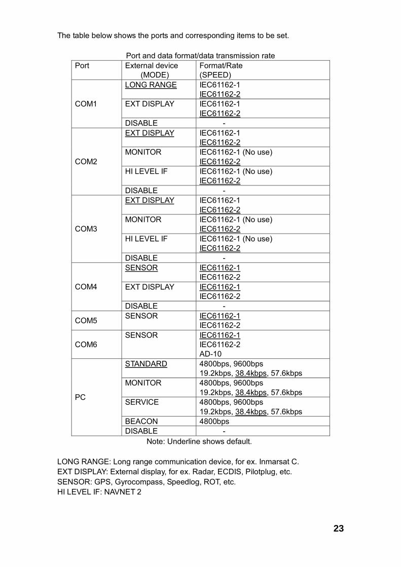
The table below shows the ports and corresponding items to be set.
Port and data format/data transmission rate Port External device
(MODE) Format/Rate (SPEED)
LONG RANGE IEC61162-1 IEC61162-2
EXT DISPLAY IEC61162-1 IEC61162-2
COM1
DISABLE - EXT DISPLAY IEC61162-1
IEC61162-2 MONITOR IEC61162-1 (No use)
IEC61162-2 HI LEVEL IF IEC61162-1 (No use)
IEC61162-2
COM2
DISABLE - EXT DISPLAY IEC61162-1
IEC61162-2 MONITOR IEC61162-1 (No use)
IEC61162-2 HI LEVEL IF IEC61162-1 (No use)
IEC61162-2
COM3
DISABLE - SENSOR IEC61162-1
IEC61162-2 EXT DISPLAY IEC61162-1
IEC61162-2 COM4
DISABLE -
COM5 SENSOR IEC61162-1 IEC61162-2
COM6 SENSOR IEC61162-1
IEC61162-2 AD-10
STANDARD 4800bps, 9600bps 19.2kbps, 38.4kbps, 57.6kbps
MONITOR 4800bps, 9600bps 19.2kbps, 38.4kbps, 57.6kbps
SERVICE 4800bps, 9600bps 19.2kbps, 38.4kbps, 57.6kbps
BEACON 4800bps
PC
DISABLE - Note: Underline shows default. LONG RANGE: Long range communication device, for ex. Inmarsat C. EXT DISPLAY: External display, for ex. Radar, ECDIS, Pilotplug, etc. SENSOR: GPS, Gyrocompass, Speedlog, ROT, etc. HI LEVEL IF: NAVNET 2

24
Priority setup 1. Press ▲ or ▼ to choose SET PRIORITY at the SET I/O PORT sub-menu and
press the [ENT] key.
[SET PRIORITY]L/L, COG, SOGHDGROT
QUIT [MENU]
PRIORITY menu
2. "L/L, COG, SOG" is selected; press the [ENT] key.
[SET L/L, COG, SOG]COM4: 1COM5: 2COM6: 3
QUIT [MENU]
3. COM4 is selected; press the [ENT] key to display the setting window.
1 2 3
4. Choose the priority level for the COM4 port (position, course over ground and speed over ground data) and press the [ENT] key. "1" is the highest and "3" is the lowest.
5. Set the priority of COM5 and COM6 similarly. Note: Do not set same number among COM4, COM5 and COM6. 6. Press the [MENU] key to return to the SET PRIORITY menu. 7. Press ▲ or ▼ to choose HDG and press the [ENT] key. 8. Set the priority for heading data similar to how you did for “L/L, COG, SOG”. 9. Press ▲ or ▼ to choose ROT and press the [ENT] key. 10. Set the priority for rate-of-turn data similarly. 11. Press the [MENU] key several times to save the settings.

25
4. ATTACHING LAN KIT (OPTION)
To connect to PC network or NAVNET 3D network, the optional LAN kit is required. Name: LAN kit Type: OP24-8 Code no.: 005-956-020
Name Code no. Qty Remark 1 NET100 board 008-535-840 1 03P9332 2 Hex. spacer 000-801-678 4
Attaching 1. Dismount the bottom cover. 2. Attach NET100 board 03P9332 to the 24P0035 board, referring to the figure
shown below.
J9
03P9332
24P0035
Spacer
Use screws removed at lidt figure.
NET Board03
Attaching 03P9332
J9
Unfasten 4 screw 24P0035
Transponder (Bottom cover removed)
SW3
3. Set DIP switch SW3 #4 as follows. • For NAVNET 3D network: SW3 #4 OFF (default)
• For PC network: SW3 #4 ON

26
Setting LAN port for PC network 1. Press the [MENU] key, choose INITIAL SETTING, enter password, choose SET
I/O PORT and press the [ENT] key to show the SET I/O PORT sub menu. 2. Press ▲ or ▼ to choose SET LAN PORT and press the [ENT] key.
[SET LAN PORT]MODE : STANDARDIP ADDRESS 172. 031. 024. 001SUB NET MASK 255. 255. 000. 000PORT NO. : 10000
QUIT [MENU] 3. Press the [ENT] key to show the mode selecting window. 4. Press ▲ or ▼ to choose suitable mode and press the [ENT] key.
STANDARD: When connecting a LAN device MONITOR: When connecting a monitor SERVICE: Data output for service man DISABLE: No connection
5. Press the [ENT] key, enter IP address in the IP ADDRESS field and press the [ENT] key. (Setting range: 000.000.000.000 to 255.255.255.255) Choose digit with ◄ or ►; set value with ▲ or ▼.
6. Press the [ENT] key, enter sub net mask in the SUB NET MASK field and press the [ENT] key. (Setting range: 000.000.000.000 to 255.255.255.255)
7. Press the [ENT] key, enter port number in the PORT NO. field and press the [ENT] key. (Setting range: 0 to 65535)
8. Press the [MENU] key several times to save the settings and close the menu. Setting LAN port for NAVNET 3D network 1. Press the [MENU] key, choose INITIAL SETTING, enter password, choose SET
I/O PORT and press the [ENT] key to show the SET I/O PORT sub menu. 2. Press ▲ or ▼ to choose SET LAN PORT and press the [ENT] key.
[SET LAN PORT] 1/2IP ADDRESS 172. 031. 024. 001SUB NET MASK 255. 255. 000. 000NAVNET PORT NO. 10000
3. Press the [ENT] key, enter IP address in the IP ADDRESS field and press the [ENT] key. (Setting range: 000.000.000.000 to 255.255.255.255) Choose digit with ◄ or ►; set value with ▲ or ▼.

27
4. Press the [ENT] key, enter sub net mask in the SUB NET MASK field and press the [ENT] key. (Setting range: 000.000.000.000 to 255.255.255.255)
5. Press the [ENT] key, enter port number in the NAVNET PORT NO. field and press the [ENT] key. (Setting range: 10000 to 30000)
6. Press▼ to show next page.
[SET LAN PORT] 2/2GATEWAY ADDRESS 000. 000. 000. 000HOST NAME : AISOAISOUTPUT : CONTINUOUSGPSOUTPUT : AUTOZDAOUTPUT : AUTO
7. Press the [ENT] key, enter gateway address in the GATEWAY ADDRESS field and press the [ENT] key. (Setting range: 000.000.000.000 to 255.255.255.255)
8. At the HOST NAME field, enter host name that is used in the NAVNET 3D(Setting range: AIS 0 to AIS 9) .
9. At the AIS OUTPUT field, set output condition. AUTO: Auto-detect of where to output AIS data. CONTINUOUS: AIS Output AIS data continuously.
10. At the GPS OUTPUT field, set GPS data (L/L, SOF, COG) output condition between AUTO and CONTINUOUS.
11. At the ZDA OUTPUT field, set time data output condition between AUTO and CONTINUOUS.
12. Press the [MENU] key several times to save the settings and close the menu.

28
5. IEC 61162-1/2 DATA SENTENCES
IEC 61162-1/2 format data is input or output from the data port COM1-COM6. The table below shows the input/output data specifications. Transponder Port Menu setting Input/Output Data format
LONG RANGE Input/Output* IEC61162-2 (38.4kbps) / IEC61162-1 (4800bps) COM1
EXT DISPLAY Input/Output* IEC61162-2 (38.4kbps) / IEC61162-1 (4800bps)
COM2 EXT DISPLAY Input/Output* IEC61162-2 (38.4kbps) / IEC61162-1 (4800bps)
COM3 EXT DISPLAY Input/Output* IEC61162-2 (38.4kbps) / IEC61162-1 (4800bps)
SENSOR Input* IEC61162-2 (38.4kbps) / IEC61162-1 (4800bps)
COM4 EXT DISPLAY Input/Output*
IEC61162-2 (38.4kbps) / IEC61162-1 (4800bps)
COM5 SENSOR Input* IEC61162-2 (38.4kbps) / IEC61162-1 (4800bps)
COM6 SENSOR Input* IEC61162-2 (38.4kbps) / IEC61162-1 (4800bps) AD-10
*: See next page for details.

29
Input data/Sentences Sentence (Priority) Contents ABM Addressed binary and safety related message ACA AIS regional channel assignment message ACK Acknowledge alarm AIR AIS interrogation request BBM UAIS broadcast binary message VSD UAIS voyage static data LRI LRF
Long Range interrogation Long Range function
DTM Datum reference GNS>GLL>GGA>RMC Position VBW>RMC>VTG>OSD Speed over ground RMC>VTG>OSD Course over ground HDT>OSD>AD-10 format Heading GBS GNSS satellite fault detection ROT>Calculated value Rate of turn SSD UAIS ship static data Output data/Sentences Sentence Contents AIVDM VHF data-link message AIVDO UAIS VHF data-link own-vessel report AIABK UAIS addressed and binary broadcast acknowledgement AILRF AILR1 AILR2 AILR3
Long-range function Long-range reply with destination for function request “A” Long-range reply for function requests “B, C, E and F” Long-range reply for function requests “I, O, P, U and W”
AIACA AIS regional channel assignment message AIALR Set alarm state AITXT Text transmission AIACS Channel management information source

A-2
ForF
A-1
502
A-1
ForF
A-1
501

A-4
ForG
PA
-017
S/G
SC
-001
A-3
A-6
For F
A-1
502
A-5
For D
B-1

Ante
nna
Cab
le S
et
CP2
0-02
700
(004
-381
-160
)
CP2
0-02
710
(004
-381
-170
)
A-8
A-7
ForF
A-1
502

Ante
nna
Cab
le S
et
CP2
0-00
300
(000
-041
-938
)
CP2
0-00
310
(000
-041
-939
)
A-9


Mar,27'07 R.Esumi


Apr.20'07 R.Esumi


3 41 2 5 6
TYPE
名前
NAMEkg
DWG. No.
SCALE
APPROVED
DRAWN
CHECKED
MASS
C
B
D
A
IEC61162-2: 38.4KBPS
IEC61162-1: 4800BPS
FA-150
U-AIS TRANSPONDER
INTERCONNECTION DIAGRAM
相互結線図
国際船舶自動識別装置
10987654321
54321
13121110987654321
10987654321
87654321
87654321
87654321
87654321
COM6_1_RD_C/AD_DATA_C
COM6_1_RD_H
COM5_1_RD_CCOM5_1_RD_H
COM4_1_RD_CCOM4_1_RD_H
COM4_JPCOM4_JP
COM4_2_RD_BCOM4_2_RD_A
COM4_TD_BCOM4_TD_A
GND_ISO
GND_ISO
COM1_JP
DISP_SW(-)DISP_SW(+)
GND_ISO
GND_ISOCOM1_JP
COM1_RD_BCOM1_RD_A
COM1_TD_BCOM1_TD_A
ACK_CACK_HALM_CALM_BALM_A
AD_CLK_CAD_CLK_H
AD_DATA_H
COM6_JPCOM6_JP
COM6_2_RD_BCOM6_2_RD_A
COM6_TD_BCOM6_TD_A
COM5_JPCOM5_JP
COM5_2_RD_BCOM5_2_RD_A
COM5_TD_BCOM5_TD_A
GND_ISO
GND_ISO
GND_ISO
GND_ISO
COM3_JPCOM3_JP
COM3_RD_BCOM3_RD_A
COM3_TD_BCOM3_TD_A
COM2_RD_B
COM2_JPCOM2_JP
COM2_RD_A
COM2_TD_BCOM2_TD_A
GND_ISO
GND_ISO
GND_ISO
GND_ISO
DISP_RD_BDISP_RD_A
GND_ISO
GND_ISODISP_TD_BDISP_TD_A
COM4
COM1
COM6
COM5
COM3
COM2
DISP
P
P
P
MJ-A10SPF0012,5m,φ8.9(10m/25m/50m/100m,OPTION)
IV-1.25sq.*1GND
MJ-A3SPF
BLKWHT
クロシロ
321
10987654321 MONITOR UNIT
FA-1502
表示部MJ-A10SPF
FG
DC_IN+DC_IN-
POWERSW_L
COM
NCFG
0V0V
SW_HRX_BRX_ATX_BTX_A
M-P-7
EANT
NJ-TP-3DXV,1m
*2
1mBUTORDISTRI-分配器
DB-1 TNC-P-3
M-P-3
1m
1m
VHF ANT
GPS ANT
VHF ANT
GPS ANT
*1
TRANSPONDER UNITトランスポンダ部
FA-1501
21
POWER
DC(-)DC(+)
DPYC-2.5 *112-24VDC
-+
*2
PE 保護アース
1φ,50/60Hz
100-115/200-230VAC
24VDC
*2
87654321
LAN
NCNCRXNNCNCRXPTXNTXP
03P9332
987654321
D-SUB 9P PC
NCCTSRTSDSR0VDTRPC_RDPC_SDNC
RJ45*3
*3
*3
*3
*3
*6
*6
EXT ALM
モモ/アカモモ/クロ
PNK/REDPNK/BLK
キ/アカキ/クロ
YEL/REDYEL/BLKWHT/REDシロ/アカ
シロ/クロ WHT/BLKハイ/アカハイ/クロ
GRY/REDGRY/BLK
P
P
P
TTYCS-4,MAX.100m*1
FUSE3A MJ-A3SPF0013,3.5m,φ6.8
ハイ/アカハイ/クロ
GRY/REDGRY/BLK
キ/アカキ/クロ
YEL/REDYEL/BLK
モモ/アカモモ/クロ
PNK/REDPNK/BLK
WHT/REDシロ/アカ
シロ/クロ WHT/BLK
*6
*6
(NORMAL CLOSE)(NORMAL OPEN)
*1
*6
*6
*3
P
P
SENSOR: GPSGYROCOMPASSSPEED LOGROT
T.YAMASAKI
T.TAKENO
NOTE:
注記
*1: SHIPYARD SUPPLY*2: OPTION*3: ADD JUMPER WHEN USING IEC61162-2.*4: PRODUCED BY AMP INC.
*2)オプション*1)造船所手配
*3)IEC61162-2使用時はジャンパーを追加する。*4)AMP社製
*6: INSULATE UNUSED WIRES.
*6)使用しない芯線は絶縁する。
IV-2sq.GND
PE 保護アースIV-1.25sq. *1
*1TTYCS-1Q,MAX.100m
TTYCS-1,MAX.100m
TTYCS-1Q,MAX.100m
TTYCS-1,MAX.100m
TTYCS-1Q,MAX.10m
*1
*1
*1
(IEC61162-2)SENSOR
(IEC61162-1)SENSOR
OR
TTYCS-1,MAX.100m*1
SENSOR(IEC61162-1)
(IEC61162-2)SENSOR
(IEC61162-1)SENSOR
(IEC61162-2)SENSOR
(IEC61162-1/2)
OR
OR
*1TTYCS-1Q,MAX.10m ALARM SYSTEM
*6
*6
*6
M-P-7
0.6m(GSC-001)
0.2m(GPA-017S)
N-P-8DFB
RG-10/UY,MAX.20m *1
TNC-J-3
TNCP-NJ
GPA-017S
GPS ANTENNAGPSアンテナ
GSC-001OR
N-P-8DFB8D-FB-CV,30/50m *2
150M-W2VNOR
FAB-151D
VHF ANTENNAVHFアンテナ
*1RG-10/UY
N-P-8DFB
RG-10/UY,MAX.20m *18D-FB-CV,30/50m *2
0.8m
GSC-001
N-J-3
N-P-8DFB
GPS/VHF ANTENNA複合空中線部
GVA-100
150M-W2VNOR
FAB-151D
*2
選択SELECT
N-J-3
-+
*1DPYC-1.5
DPYC-2.5*1
DCOUT
ACIN
DCIN SUPPLY UNIT
AC/DC POWER電源ユニットAC/DC
MJ-A10SPF0012,5/10/25/50/100m,φ9
10987654321 MONITOR UNIT
FA-1502
表示部MJ-A10SPF
SW_L
COM
NCFG
0V0V
SW_HRX_BRX_ATX_BTX_A
87
DISP
87654321
RD_BRD_A
TD_BTD_A
GND_ISO
GND_ISO
P
P
P
P
No.2 表示部 No.2 MONITOR UNIT
COM2/COM3
*6
DISP_SW(-)DISP_SW(+)
7
1
GND
SD
DGPS BEACONDGPSビーコン受信機
RECEIVERGR-80
FM14-7PDATA
TTYCS-4,MAX.100m*1
TTYCS-1Q,MAX.100m*1
STP CABLE(CAT5)*1
(MAX.15m)RS-232C CABLE
*3
PC
PC
GYROCOMPASSAD-100*5
*5)ジャイロにIEC61162インターフェイスがないときのみ接続可能。
IEC61162 INTERFACE.
*5: GYRO CONVERTOR IS AVAILABLE WHEN GYROCOMPASS HAS NO
PR-240
PR-240*2
DPYC-2.5
*1
*1
DPYC-1.51φ,50/60Hz100-115/200-230VAC
12-24VDC
24VDC
C4431-C01- M
Jun. 26 '07
Jun. 26 '07
P
P
*6
206486-1 206485
RX BRX ATX BTX ATX A
SHIELD 96541
*2OP24-3PILOT PLUG UNITパイロットプラグユニット
*1TTYCS-4,MAX.30m
*4
12345
PC
GND
RD-A
TD-ATD-B
RD-B
P
P
TTYCS-4,MAX.100m*1
*6
GND
RD-A
TD-ATD-B
RD-B
COM1~COM3は等価に使用可能COM1~COM3 USED EQUIVALENT
IV-1.25sq. *1
RADAR/ECDIS(IEC61162-1/2)
RADAR/ECDIS(IEC61162-1/2)
EXT DISPLAY
Jul.3'07 R.Esumi


![TRANSPONDER BYPASS: SENTRY KEY [INSTALLATION GUIDE] · Transponder Bypass: RF override via induction w/ loop antenna (transponder incl. no key required). This transponder bypass kit](https://img.pdfslide.net/doc/110x75/5f51bec37e825f53705baf2b/transponder-bypass-sentry-key-installation-guide-transponder-bypass-rf-override.jpg)