Embed Size (px)
Citation preview
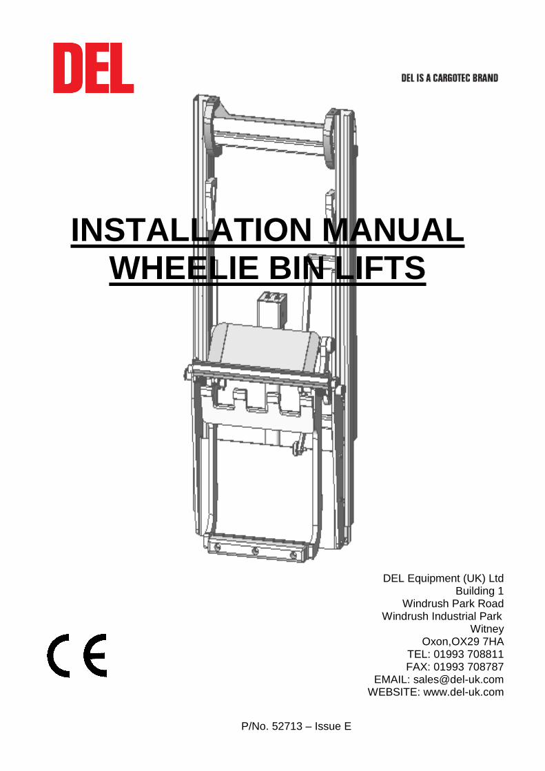
INSTALLATION MANUAL WHEELIE BIN LIFTS
P/No. 52713 – Issue E
DEL Equipment (UK) Ltd Building 1
Windrush Park Road Windrush Industrial Park
Witney Oxon,OX29 7HA
TEL: 01993 708811 FAX: 01993 708787
EMAIL: [email protected] WEBSITE: www.del-uk.com
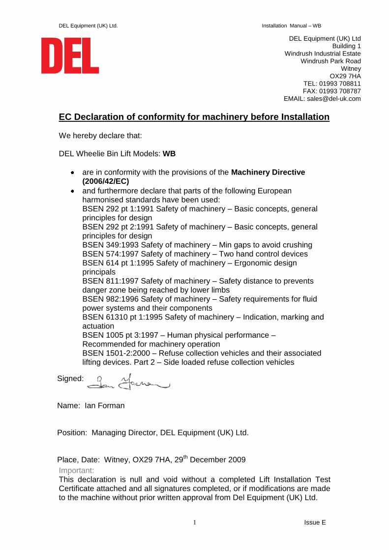
DEL Equipment (UK) Ltd. Installation Manual – WB
Issue E 1
EC Declaration of conformity for machinery before Installation We hereby declare that:
DEL Wheelie Bin Lift Models: WB
are in conformity with the provisions of the Machinery Directive (2006/42/EC)
and furthermore declare that parts of the following European harmonised standards have been used: BSEN 292 pt 1:1991 Safety of machinery – Basic concepts, general principles for design BSEN 292 pt 2:1991 Safety of machinery – Basic concepts, general principles for design BSEN 349:1993 Safety of machinery – Min gaps to avoid crushing BSEN 574:1997 Safety of machinery – Two hand control devices BSEN 614 pt 1:1995 Safety of machinery – Ergonomic design principals BSEN 811:1997 Safety of machinery – Safety distance to prevents danger zone being reached by lower limbs BSEN 982:1996 Safety of machinery – Safety requirements for fluid power systems and their components BSEN 61310 pt 1:1995 Safety of machinery – Indication, marking and actuation BSEN 1005 pt 3:1997 – Human physical performance – Recommended for machinery operation BSEN 1501-2:2000 – Refuse collection vehicles and their associated lifting devices. Part 2 – Side loaded refuse collection vehicles
Important: This declaration is null and void without a completed Lift Installation Test Certificate attached and all signatures completed, or if modifications are made to the machine without prior written approval from Del Equipment (UK) Ltd.
Signed: Name: Ian Forman Position: Managing Director, DEL Equipment (UK) Ltd. Place, Date: Witney, OX29 7HA, 29th December 2009
DEL Equipment (UK) Ltd Building 1
Windrush Industrial Estate Windrush Park Road
Witney OX29 7HA
TEL: 01993 708811 FAX: 01993 708787
EMAIL: [email protected]
DEL Equipment (UK) Ltd. Installation Manual – WB
Issue E 2
INTRODUCTION
This manual covers the installation of the Wheelie bin lift range. The correct installation and setting up of the lift is vital to the working life of the lift. Safety must be regarded as of paramount importance during installation. A risk assessment for the installation and commissioning of the bin lift is required before starting work. Read this manual fully before commencing work. The lift is heavy and can crush. Never work under the lift unless it is securely supported and always disconnect the vehicle battery before starting work.
Do not make any design modification to the Wheelie bin lift unless written permission is first obtained from DEL Equipment (UK) Ltd. Please note that any unauthorised modification may: -
Invalidate the warranty
Lead to equipment failure
Create a hazard that is not immediately obvious at the time of installation.
If you are unsure about any aspect of the installation procedure please contact DEL Service.
CONTENTS
1. Operating Systems………………………………………………….…….….3
2. Installation procedure...............................................................................4
3. Location of control positions…………………………….………..…...........12
4. In-line fuses and the earth cable…….……………………………….…......13
5. Power pack relief valve………………………………………….….….........14
6. Chain adjustment……..…………………………………………....………...15
7. Warning decals……………………………………………...…..…….……...16
8. Tests after installation………….………………………………...….............20
9. Test checklist…………………………………………………………….........22
10. Technical Information………………………………………………….…......23 - Wiring Diagrams. - Torque settings - Hydraulic fluid - Weights - Centre of gravity
11. DEL Warranty Registration Form..............................................................31
12. Tailift Test Certificate................................................................................32
IMPORTANT
This manual forms part of the Inspection record for the lift, and should be passed on to the end user, together with the operator’s manual.
DEL Equipment (UK) Ltd. Installation Manual – WB
3 Issue D
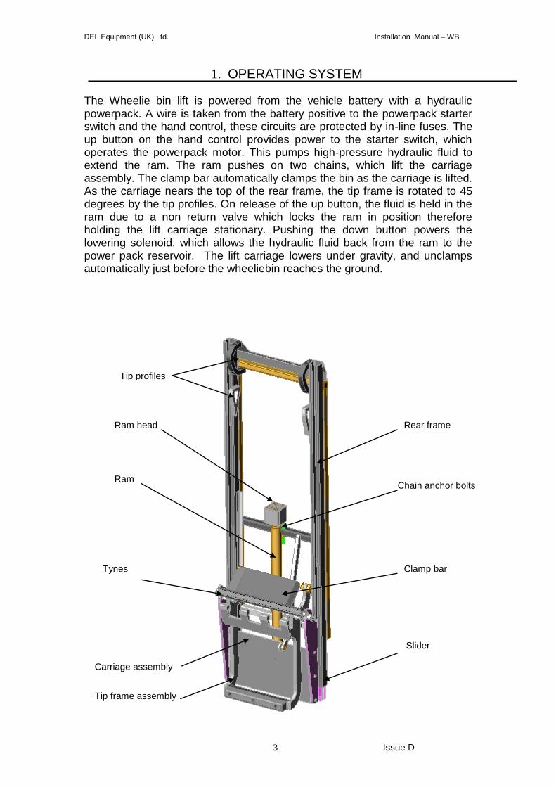
1. OPERATING SYSTEM
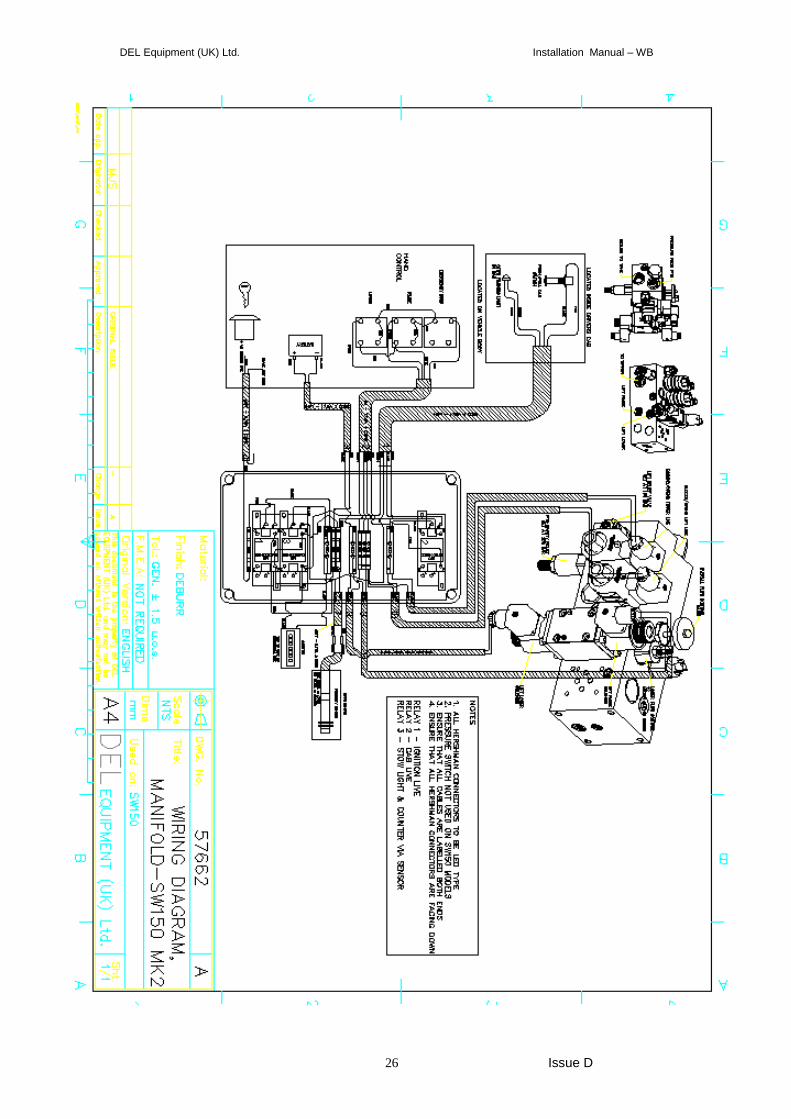
The Wheelie bin lift is powered from the vehicle battery with a hydraulic powerpack. A wire is taken from the battery positive to the powerpack starter switch and the hand control, these circuits are protected by in-line fuses. The up button on the hand control provides power to the starter switch, which operates the powerpack motor. This pumps high-pressure hydraulic fluid to extend the ram. The ram pushes on two chains, which lift the carriage assembly. The clamp bar automatically clamps the bin as the carriage is lifted. As the carriage nears the top of the rear frame, the tip frame is rotated to 45 degrees by the tip profiles. On release of the up button, the fluid is held in the ram due to a non return valve which locks the ram in position therefore holding the lift carriage stationary. Pushing the down button powers the lowering solenoid, which allows the hydraulic fluid back from the ram to the power pack reservoir. The lift carriage lowers under gravity, and unclamps automatically just before the wheeliebin reaches the ground.
Ram
Rear frame Ram head
Tip profiles
Clamp bar
Chain anchor bolts
Carriage assembly
Slider
Tip frame assembly
Tynes
DEL Equipment (UK) Ltd. Installation Manual – WB
4 Issue D
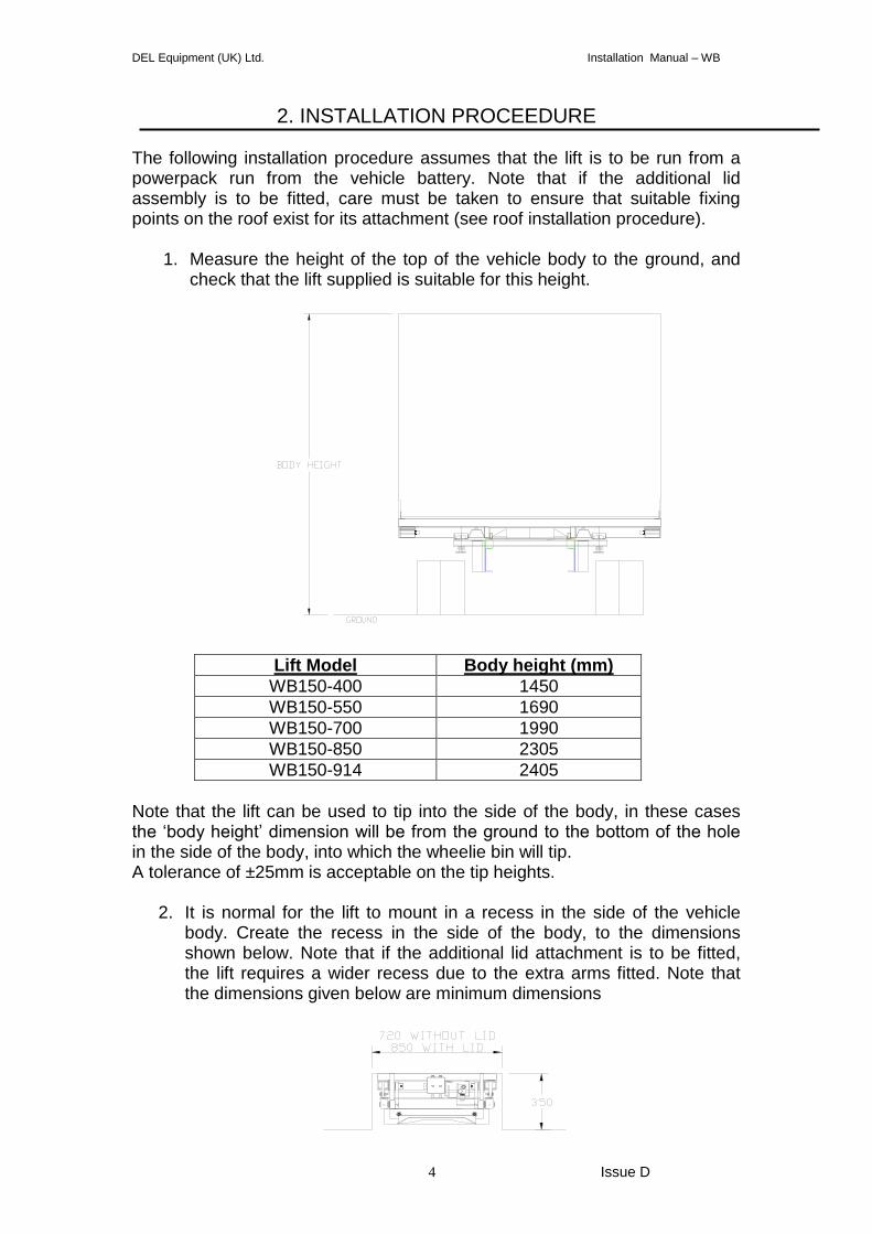
2. INSTALLATION PROCEEDURE
The following installation procedure assumes that the lift is to be run from a powerpack run from the vehicle battery. Note that if the additional lid assembly is to be fitted, care must be taken to ensure that suitable fixing points on the roof exist for its attachment (see roof installation procedure).
1. Measure the height of the top of the vehicle body to the ground, and check that the lift supplied is suitable for this height.
Lift Model Body height (mm)
WB150-400 1450
WB150-550 1690
WB150-700 1990
WB150-850 2305
WB150-914 2405
Note that the lift can be used to tip into the side of the body, in these cases the ‘body height’ dimension will be from the ground to the bottom of the hole in the side of the body, into which the wheelie bin will tip. A tolerance of ±25mm is acceptable on the tip heights.
2. It is normal for the lift to mount in a recess in the side of the vehicle body. Create the recess in the side of the body, to the dimensions shown below. Note that if the additional lid attachment is to be fitted, the lift requires a wider recess due to the extra arms fitted. Note that the dimensions given below are minimum dimensions
DEL Equipment (UK) Ltd. Installation Manual – WB
5 Issue D
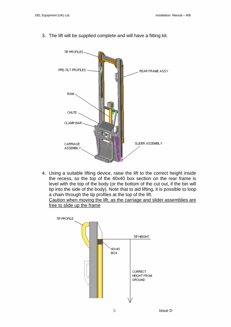
3. The lift will be supplied complete and will have a fitting kit.
4. Using a suitable lifting device, raise the lift to the correct height inside
the recess, so the top of the 40x40 box section on the rear frame is level with the top of the body (or the bottom of the cut out, if the bin will tip into the side of the body). Note that to aid lifting, it is possible to loop a chain through the tip profiles at the top of the lift. Caution when moving the lift, as the carriage and slider assemblies are free to slide up the frame
DEL Equipment (UK) Ltd. Installation Manual – WB
6 Issue D
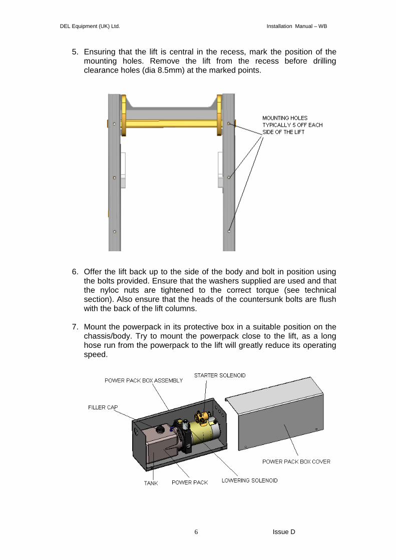
5. Ensuring that the lift is central in the recess, mark the position of the mounting holes. Remove the lift from the recess before drilling clearance holes (dia 8.5mm) at the marked points.
6. Offer the lift back up to the side of the body and bolt in position using
the bolts provided. Ensure that the washers supplied are used and that the nyloc nuts are tightened to the correct torque (see technical section). Also ensure that the heads of the countersunk bolts are flush with the back of the lift columns.
7. Mount the powerpack in its protective box in a suitable position on the
chassis/body. Try to mount the powerpack close to the lift, as a long hose run from the powerpack to the lift will greatly reduce its operating speed.
DEL Equipment (UK) Ltd. Installation Manual – WB
7 Issue D
8. Run the 2 core cable to the cab (provided in the fitting kit) and fit the cab on/off switch following the wiring diagram.
9. Mount the push button control in its bracket to the side of the body.
Ensure that its position is far enough from the lift so that the operator can work safely, but still has a good view of the working area of the lift (see control position section).
10. Wire the hand control to the powerpack following the wiring diagram. 11. Run the power and earth cables from the vehicle battery to the
powerpack. On tipper bodies, these will need to run along the chassis to the hinge then along the tipping part of the body to the powerpack. Ensure that the cables are held securely and protected where they loop at the body hinge. Ensure that the in-line mega fuse on the power cable is mounted as close to the battery as possible and in a position least susceptible to the elements.
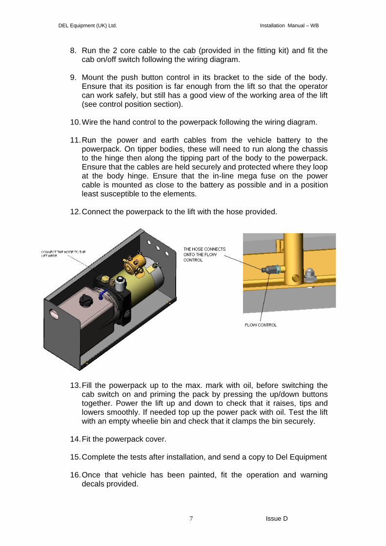
12. Connect the powerpack to the lift with the hose provided.
13. Fill the powerpack up to the max. mark with oil, before switching the
cab switch on and priming the pack by pressing the up/down buttons together. Power the lift up and down to check that it raises, tips and lowers smoothly. If needed top up the power pack with oil. Test the lift with an empty wheelie bin and check that it clamps the bin securely.
14. Fit the powerpack cover.
15. Complete the tests after installation, and send a copy to Del Equipment
16. Once that vehicle has been painted, fit the operation and warning
decals provided.
DEL Equipment (UK) Ltd. Installation Manual – WB
8 Issue D
72289 – Isolate tailift – located next to the cab switch 52314 – bin lift operation – located next to the hand control 75757 – max load – located next to the hand control 75771 – isolate power – located on the power pack box cover 75758 – hatched sticker – located on the outer edge of each tip arm 52316 – Elevating binlift – located next to the hand control.
INSTALLATION OF ADDITIONAL LID ASSEMBLY
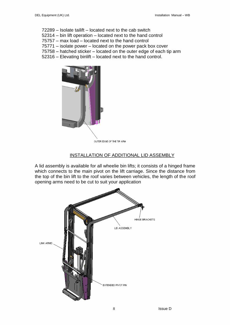
A lid assembly is available for all wheelie bin lifts; it consists of a hinged frame which connects to the main pivot on the lift carriage. Since the distance from the top of the bin lift to the roof varies between vehicles, the length of the roof opening arms need to be cut to suit your application
DEL Equipment (UK) Ltd. Installation Manual – WB
9 Issue D
1. The lid assembly will be delivered in a kit consisting of –
Lid assembly – 1 off
Mounting brackets – 2 off
Link arms – 2 off
Link arm brackets – 2 off (fitted to lift)
Extended pivot pins – 2 off (will be fitted to lift)
Mounting bolts, nuts and washers.
Link arm pivot bolts and nuts.
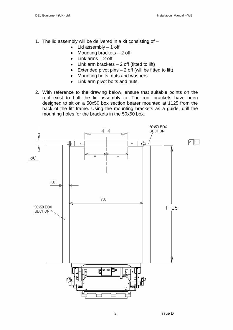
2. With reference to the drawing below, ensure that suitable points on the roof exist to bolt the lid assembly to. The roof brackets have been designed to sit on a 50x50 box section bearer mounted at 1125 from the back of the lift frame. Using the mounting brackets as a guide, drill the mounting holes for the brackets in the 50x50 box.
DEL Equipment (UK) Ltd. Installation Manual – WB
10 Issue D
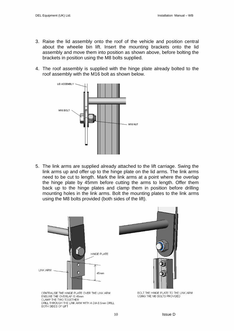
3. Raise the lid assembly onto the roof of the vehicle and position central
about the wheelie bin lift. Insert the mounting brackets onto the lid assembly and move them into position as shown above, before bolting the brackets in position using the M8 bolts supplied.
4. The roof assembly is supplied with the hinge plate already bolted to the
roof assembly with the M16 bolt as shown below.
5. The link arms are supplied already attached to the lift carriage. Swing the
link arms up and offer up to the hinge plate on the lid arms. The link arms need to be cut to length. Mark the link arms at a point where the overlap the hinge plate by 45mm before cutting the arms to length. Offer them back up to the hinge plates and clamp them in position before drilling mounting holes in the link arms. Bolt the mounting plates to the link arms using the M8 bolts provided (both sides of the lift).
DEL Equipment (UK) Ltd. Installation Manual – WB
11 Issue D
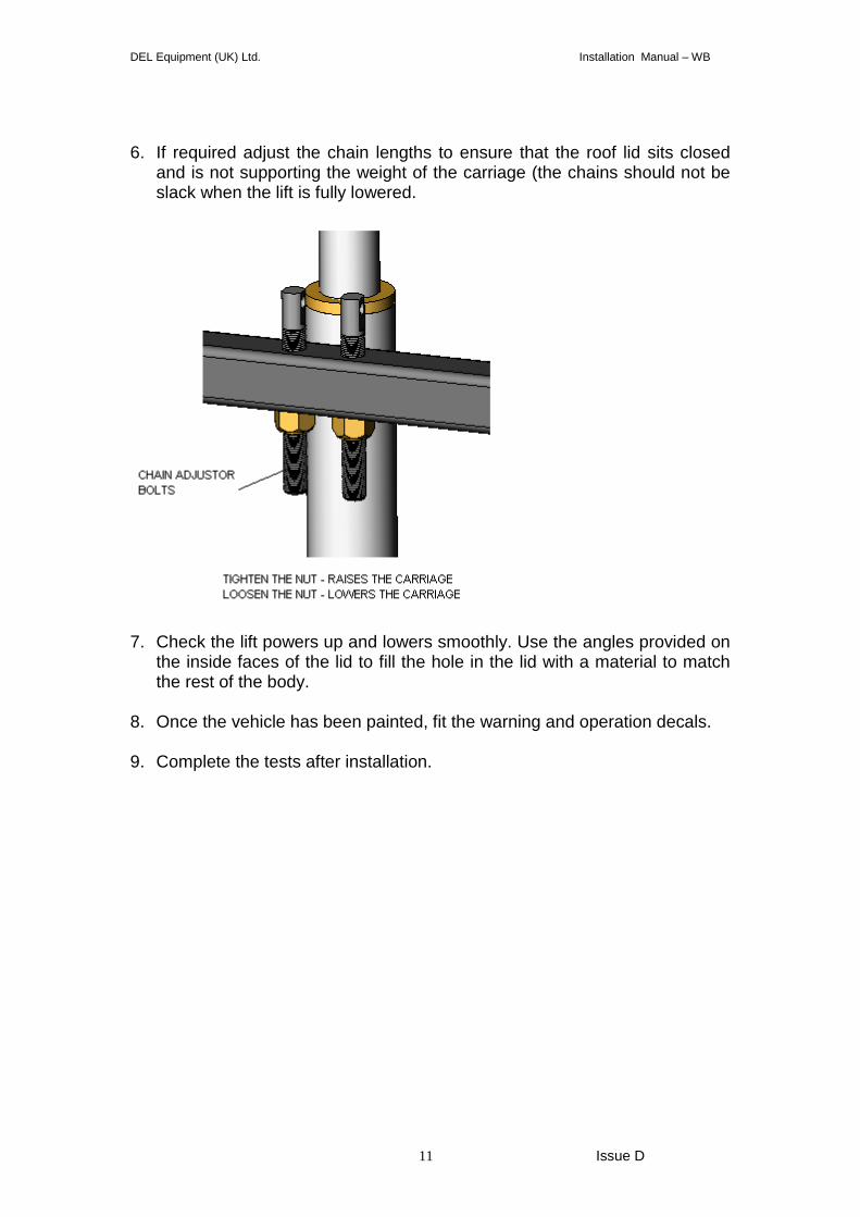
6. If required adjust the chain lengths to ensure that the roof lid sits closed
and is not supporting the weight of the carriage (the chains should not be slack when the lift is fully lowered.
7. Check the lift powers up and lowers smoothly. Use the angles provided on
the inside faces of the lid to fill the hole in the lid with a material to match the rest of the body.
8. Once the vehicle has been painted, fit the warning and operation decals. 9. Complete the tests after installation.
DEL Equipment (UK) Ltd. Installation Manual – WB
12 Issue D
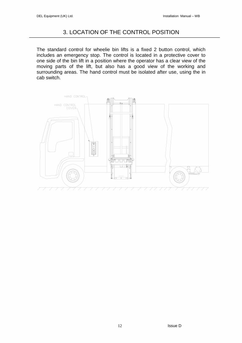
3. LOCATION OF THE CONTROL POSITION
The standard control for wheelie bin lifts is a fixed 2 button control, which includes an emergency stop. The control is located in a protective cover to one side of the bin lift in a position where the operator has a clear view of the moving parts of the lift, but also has a good view of the working and surrounding areas. The hand control must be isolated after use, using the in cab switch.
DEL Equipment (UK) Ltd. Installation Manual – WB
13 Issue D
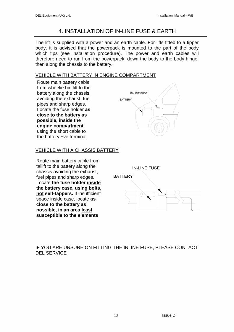
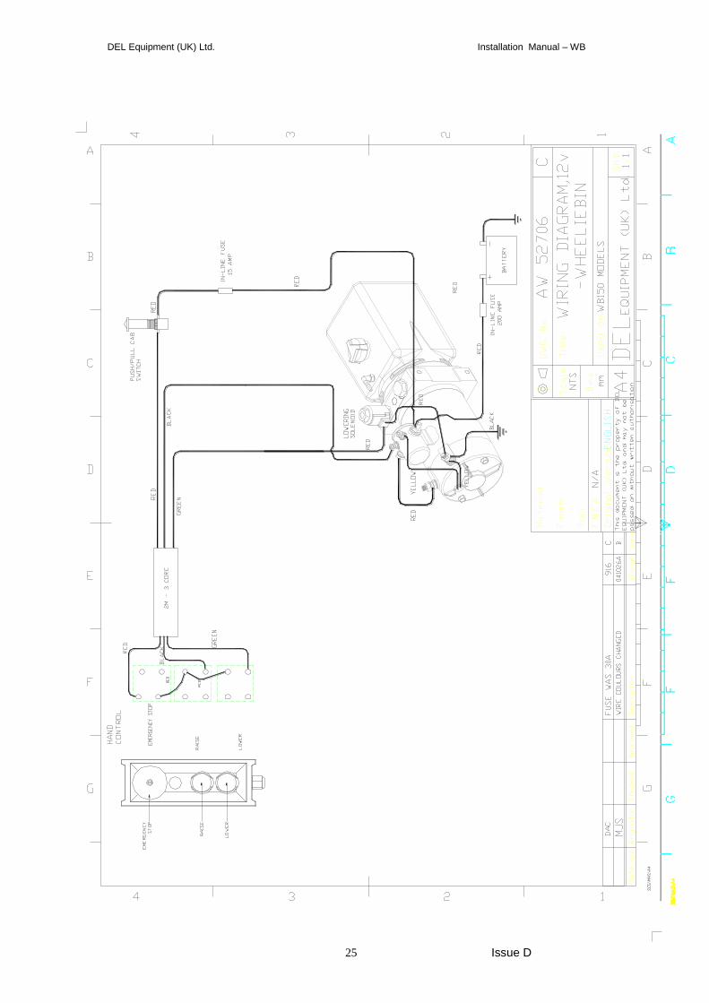
4. INSTALLATION OF IN-LINE FUSE & EARTH The lift is supplied with a power and an earth cable. For lifts fitted to a tipper body, it is advised that the powerpack is mounted to the part of the body which tips (see installation procedure). The power and earth cables will therefore need to run from the powerpack, down the body to the body hinge, then along the chassis to the battery. VEHICLE WITH BATTERY IN ENGINE COMPARTMENT
VEHICLE WITH A CHASSIS BATTERY
IF YOU ARE UNSURE ON FITTING THE INLINE FUSE, PLEASE CONTACT DEL SERVICE
Route main battery cable from wheelie bin lift to the battery along the chassis avoiding the exhaust, fuel pipes and sharp edges. Locate the fuse holder as close to the battery as possible, inside the engine compartment using the short cable to the battery +ve terminal
Route main battery cable from tailift to the battery along the chassis avoiding the exhaust, fuel pipes and sharp edges. Locate the fuse holder inside the battery case, using bolts, not self-tappers. If insufficient space inside case, locate as close to the battery as possible, in an area least susceptible to the elements
BATTERY
IN-LINE FUSE
BATTERY

DEL Equipment (UK) Ltd. Installation Manual – WB
14 Issue D
5. RELIEF VALVE
The powerpack relief valve has been factory set, if for maintenance purposes the valve needs to be adjusted, please contact the DEL service department.
DEL Equipment (UK) Ltd. Installation Manual – WB
15 Issue D
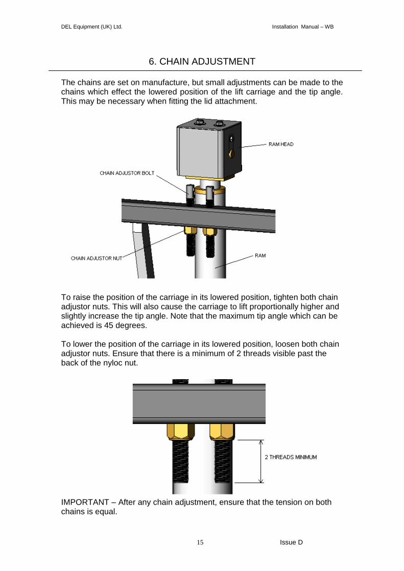
6. CHAIN ADJUSTMENT
The chains are set on manufacture, but small adjustments can be made to the chains which effect the lowered position of the lift carriage and the tip angle. This may be necessary when fitting the lid attachment.
To raise the position of the carriage in its lowered position, tighten both chain adjustor nuts. This will also cause the carriage to lift proportionally higher and slightly increase the tip angle. Note that the maximum tip angle which can be achieved is 45 degrees. To lower the position of the carriage in its lowered position, loosen both chain adjustor nuts. Ensure that there is a minimum of 2 threads visible past the back of the nyloc nut.
IMPORTANT – After any chain adjustment, ensure that the tension on both chains is equal.
DEL Equipment (UK) Ltd. Installation Manual – WB
16 Issue D
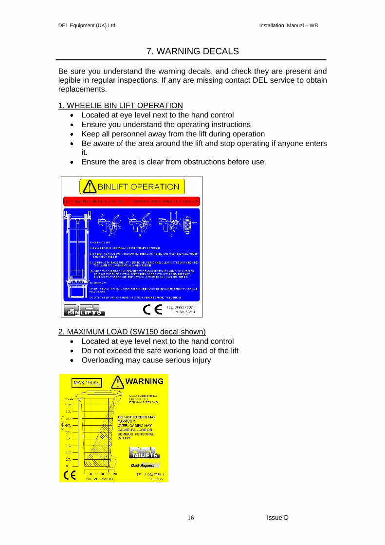
7. WARNING DECALS
Be sure you understand the warning decals, and check they are present and legible in regular inspections. If any are missing contact DEL service to obtain replacements.
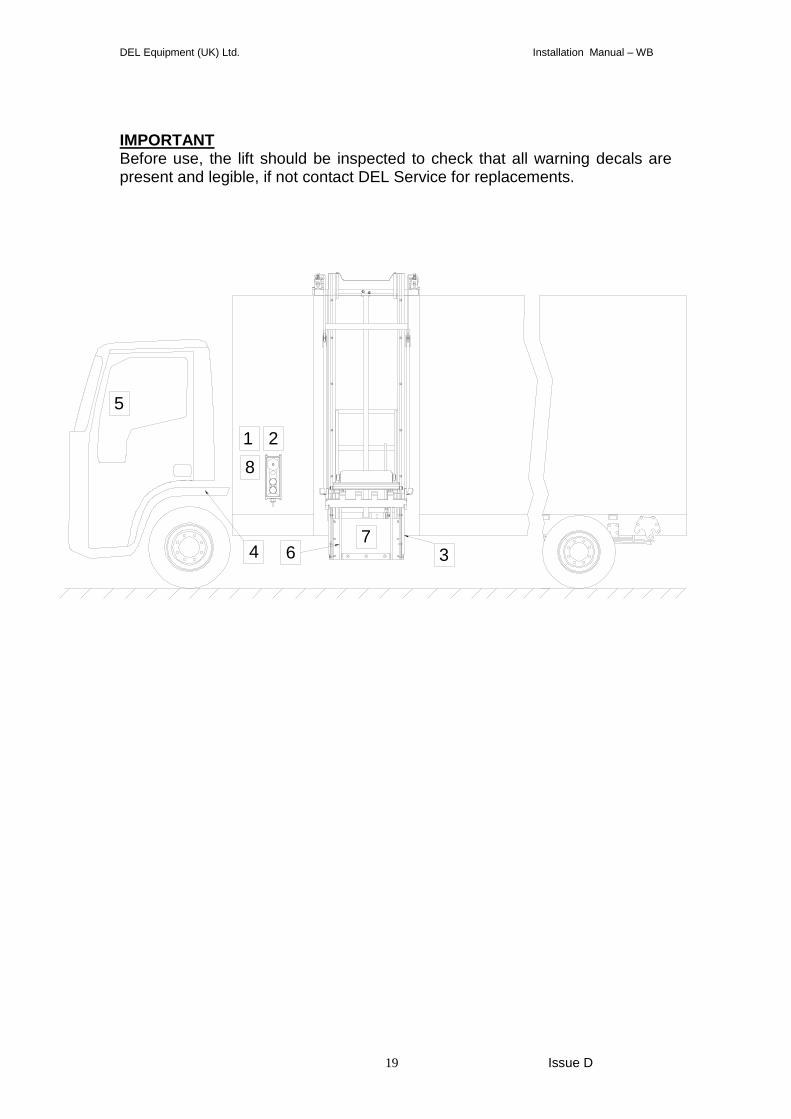
1. WHEELIE BIN LIFT OPERATION
Located at eye level next to the hand control
Ensure you understand the operating instructions
Keep all personnel away from the lift during operation
Be aware of the area around the lift and stop operating if anyone enters it.
Ensure the area is clear from obstructions before use.
2. MAXIMUM LOAD (SW150 decal shown)
Located at eye level next to the hand control
Do not exceed the safe working load of the lift
Overloading may cause serious injury
DEL Equipment (UK) Ltd. Installation Manual – WB
17 Issue D
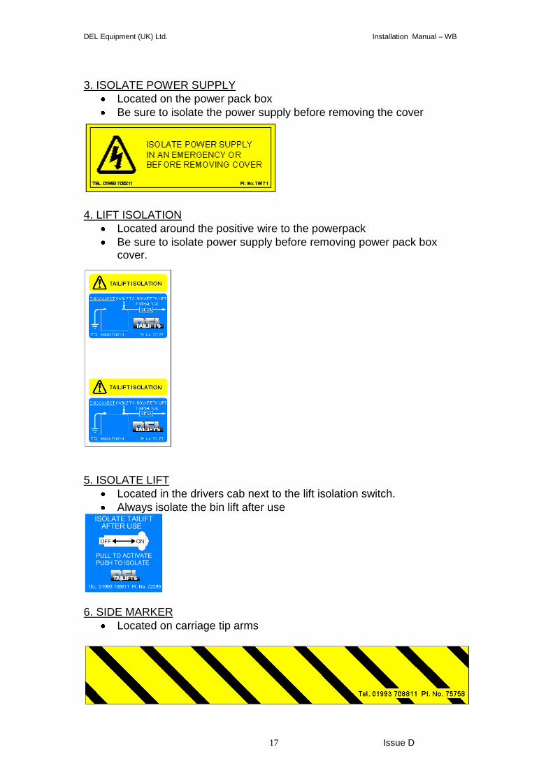
3. ISOLATE POWER SUPPLY
Located on the power pack box
Be sure to isolate the power supply before removing the cover
4. LIFT ISOLATION
Located around the positive wire to the powerpack
Be sure to isolate power supply before removing power pack box cover.
5. ISOLATE LIFT
Located in the drivers cab next to the lift isolation switch.
Always isolate the bin lift after use
6. SIDE MARKER
Located on carriage tip arms
DEL Equipment (UK) Ltd. Installation Manual – WB
18 Issue D
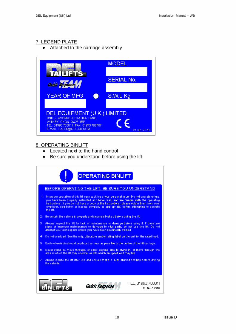
7. LEGEND PLATE
Attached to the carriage assembly
8. OPERATING BINLIFT
Located next to the hand control
Be sure you understand before using the lift
DEL Equipment (UK) Ltd. Installation Manual – WB
19 Issue D
IMPORTANT Before use, the lift should be inspected to check that all warning decals are present and legible, if not contact DEL Service for replacements.
1 2
34
5
67
8
DEL Equipment (UK) Ltd. Installation Manual – WB
20 Issue D
8. TESTS AFTER INSTALLATION
After the lift has been initially installed the following tests MUST be completed to ensure the lift has been installed and set up correctly in accordance with CE regulations. The results of the test should be entered on the test certificate provided in the back of this manual and a copy returned to DEL Equipment (UK) Ltd, the original should be kept in the manual as part of the inspection record for the lift. IMPORTANT – CE REGULATIONS REQUIRE THE TEST CERTIFICATE TO BE COMPLETED AND RETURNED TO DEL Equipment (UK) Ltd
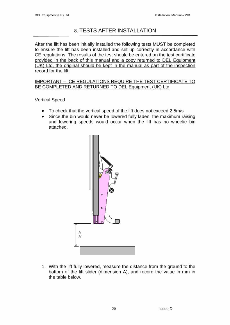
Vertical Speed
To check that the vertical speed of the lift does not exceed 2.5m/s
Since the bin would never be lowered fully laden, the maximum raising and lowering speeds would occur when the lift has no wheelie bin attached.
1. With the lift fully lowered, measure the distance from the ground to the bottom of the lift slider (dimension A), and record the value in mm in the table below.
DEL Equipment (UK) Ltd. Installation Manual – WB
21 Issue D
2. With a stopwatch, record the time taken to fully raise the lift, and record the time and the new distance (in mm) from the bottom of the lift sliders to the ground (dimension A’) in the table below.
3. Calculate the distance travelled by subtracting dimension A from
Dimension A’ and record in the table.
4. Calculate the vertical raising speed by dividing the distance found in part 3 above, by the time (in seconds) and record in the table. The speed should not exceed 2500mm/s.
5. With a stopwatch, record the time taken to lower the lift and record the
time in the table.
6. Calculate the lowering speed and record in the table. Check that the speed does not exceed 2500mm/s.
Dimension A
(mm) Dimension A’
(mm) Distance travelled
(mm)
Raising time
(secs)
Vertical speed (mm/s)
Lowering time (secs)
Lowering speed (mm/s)
If either of the speeds above exceed the stated value, please contact DEL service. Function Test
To check the lift operates safely and correctly 1. With the lift carriage fully lowered, and following the operating procedure,
offer up an empty wheelie bin of the correct capacity (120L, 240L, 340L) to the lift. Press the raise button and check that the lift clamps the bin securely within the first few feet of movement. Check that the lift stops raising as soon as the button is released and that the emergency stop button works correctly.
2. Continue pressing the raise button and check that the lift tips the bin
smoothly. Release the raise button when the lift reaches its fully tipped position.
3. Lower the bin back to the ground checking that the lift lowers smoothly,
stops as soon as the lower button is released and unclamps the bin as it nears the ground.
If the lift fails to clamp the bin or does not operate smoothly, please contact DEL Service.
DEL Equipment (UK) Ltd. Installation Manual – WB
22 Issue D
Dynamic Test
To check that the lift operates safely at the specified dynamic load.
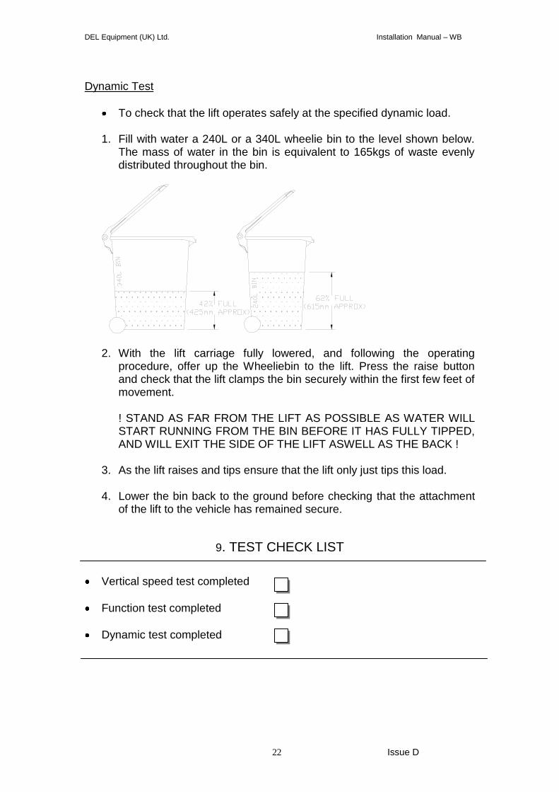
1. Fill with water a 240L or a 340L wheelie bin to the level shown below. The mass of water in the bin is equivalent to 165kgs of waste evenly distributed throughout the bin.
2. With the lift carriage fully lowered, and following the operating
procedure, offer up the Wheeliebin to the lift. Press the raise button and check that the lift clamps the bin securely within the first few feet of movement.
! STAND AS FAR FROM THE LIFT AS POSSIBLE AS WATER WILL START RUNNING FROM THE BIN BEFORE IT HAS FULLY TIPPED, AND WILL EXIT THE SIDE OF THE LIFT ASWELL AS THE BACK !
3. As the lift raises and tips ensure that the lift only just tips this load.
4. Lower the bin back to the ground before checking that the attachment
of the lift to the vehicle has remained secure.
9. TEST CHECK LIST
Vertical speed test completed
Function test completed
Dynamic test completed
DEL Equipment (UK) Ltd. Installation Manual – WB
23 Issue D
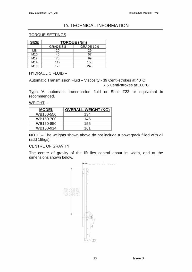
10. TECHNICAL INFORMATION
TORQUE SETTINGS –
SIZE TORQUE (Nm) GRADE 8.8 GRADE 10.9
M8 20 29
M10 40 57
M12 70 99
M14 112 158
M16 175 246
HYDRAULIC FLUID –
Automatic Transmission Fluid – Viscosity - 39 Centi-strokes at 40 C
7.5 Centi-strokes at 100 C
Type ‘A’ automatic transmission fluid or Shell T22 or equivalent is recommended.
WEIGHT –
MODEL OVERALL WEIGHT (KG)
WB150-550 134
WB150-700 145
WB150-850 155
WB150-914 161
NOTE – The weights shown above do not include a powerpack filled with oil (add 15kgs).
CENTRE OF GRAVITY
The centre of gravity of the lift lies central about its width, and at the dimensions shown below.
DEL Equipment (UK) Ltd. Installation Manual – WB
24 Issue D
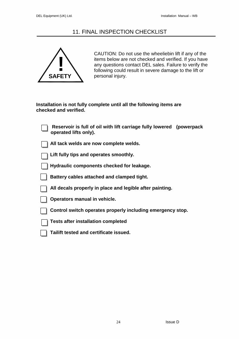
11. FINAL INSPECTION CHECKLIST
Installation is not fully complete until all the following items are checked and verified.
Reservoir is full of oil with lift carriage fully lowered (powerpack operated lifts only).
All tack welds are now complete welds. Lift fully tips and operates smoothly. Hydraulic components checked for leakage. Battery cables attached and clamped tight. All decals properly in place and legible after painting. Operators manual in vehicle. Control switch operates properly including emergency stop. Tests after installation completed
Tailift tested and certificate issued.
SAFETY
!
CAUTION: Do not use the wheeliebin lift if any of the items below are not checked and verified. If you have any questions contact DEL sales. Failure to verify the following could result in severe damage to the lift or personal injury.
DEL Equipment (UK) Ltd. Installation Manual – WB
25 Issue D
DEL Equipment (UK) Ltd. Installation Manual – WB
26 Issue D
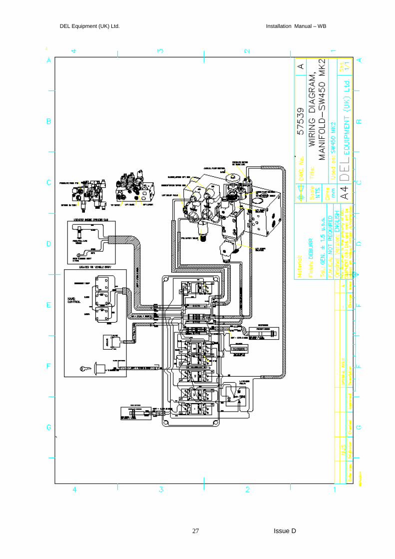
DEL Equipment (UK) Ltd. Installation Manual – WB
27 Issue D
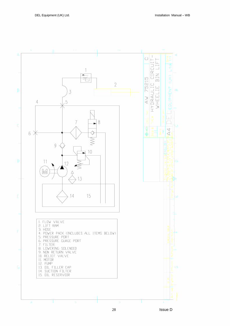
DEL Equipment (UK) Ltd. Installation Manual – WB
28 Issue D
DEL Equipment (UK) Ltd. Installation Manual – WB
29 Issue D
DEL Equipment (UK) Ltd. Installation Manual – WB
30 Issue D
DEL Equipment (UK) Ltd. Installation Manual – WB
31 Issue D
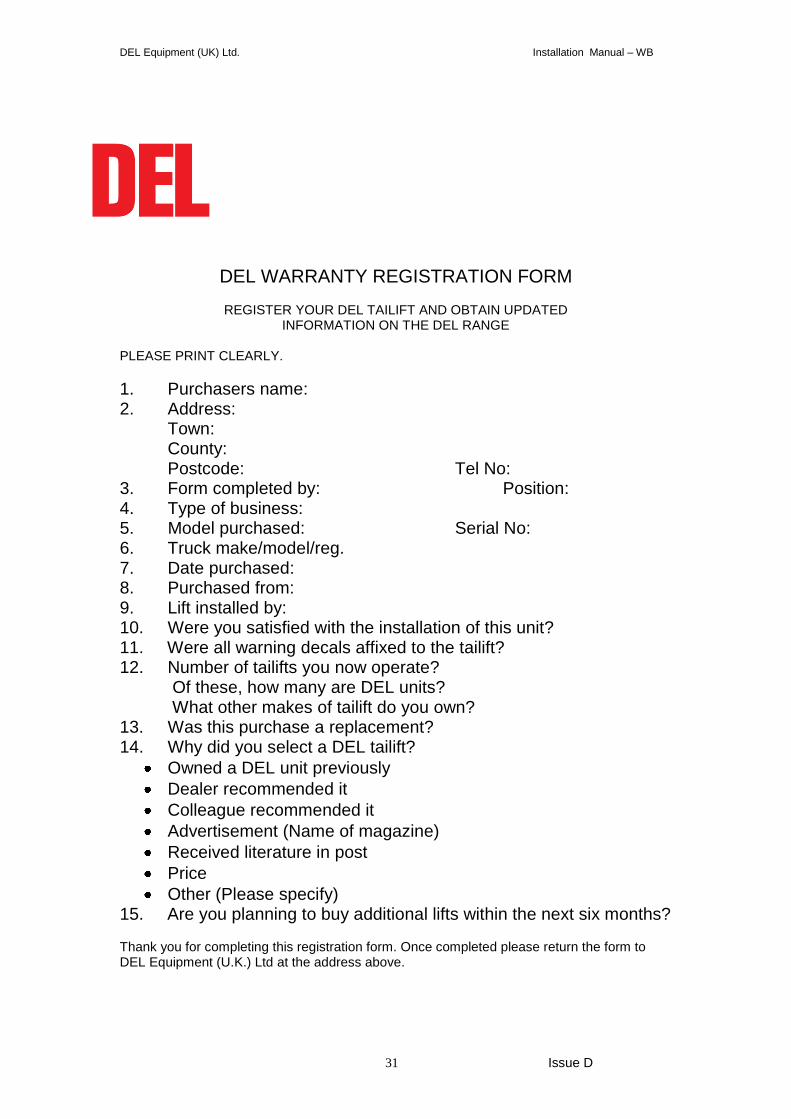
DEL WARRANTY REGISTRATION FORM
REGISTER YOUR DEL TAILIFT AND OBTAIN UPDATED
INFORMATION ON THE DEL RANGE PLEASE PRINT CLEARLY.
1. Purchasers name: 2. Address:
Town: County: Postcode: Tel No:
3. Form completed by: Position: 4. Type of business: 5. Model purchased: Serial No: 6. Truck make/model/reg. 7. Date purchased: 8. Purchased from: 9. Lift installed by: 10. Were you satisfied with the installation of this unit? 11. Were all warning decals affixed to the tailift? 12. Number of tailifts you now operate?
Of these, how many are DEL units? What other makes of tailift do you own?
13. Was this purchase a replacement? 14. Why did you select a DEL tailift?
Owned a DEL unit previously
Dealer recommended it
Colleague recommended it
Advertisement (Name of magazine)
Received literature in post
Price
Other (Please specify) 15. Are you planning to buy additional lifts within the next six months? Thank you for completing this registration form. Once completed please return the form to DEL Equipment (U.K.) Ltd at the address above.
DEL Equipment (UK) Ltd. Installation Manual – WB
32 Issue D
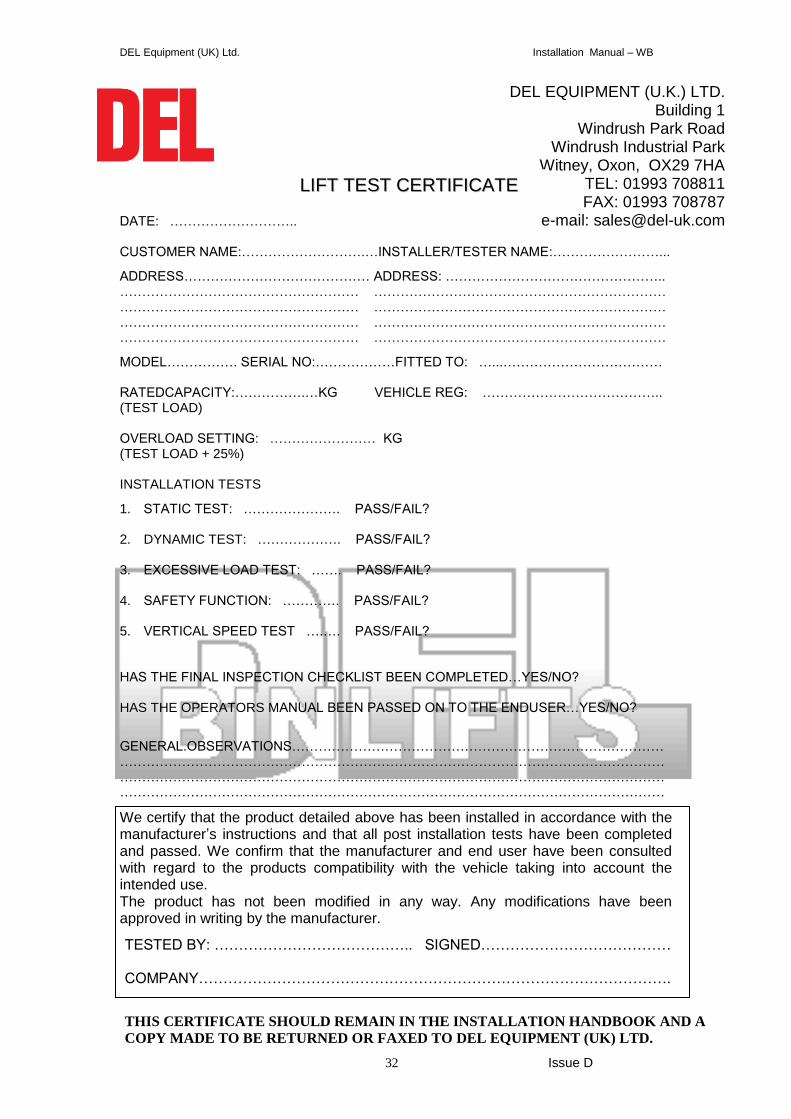
DATE: ……………………….. CUSTOMER NAME:……………………….…INSTALLER/TESTER NAME:……………………...
ADDRESS…………………………………… ADDRESS: ………………………………………….. ……………………………………………… ………………………………………………………… ……………………………………………… ………………………………………………………… ……………………………………………… ………………………………………………………… ……………………………………………… …………………………………………………………
MODEL……………. SERIAL NO:………………FITTED TO: …...……………………………… RATEDCAPACITY:…………….…KG VEHICLE REG: ………………………………….. (TEST LOAD) OVERLOAD SETTING: …………………… KG (TEST LOAD + 25%)
INSTALLATION TESTS
1. STATIC TEST: …………………. PASS/FAIL? 2. DYNAMIC TEST: ………………. PASS/FAIL? 3. EXCESSIVE LOAD TEST: ……. PASS/FAIL? 4. SAFETY FUNCTION: …………. PASS/FAIL?
5. VERTICAL SPEED TEST ….…. PASS/FAIL?
HAS THE FINAL INSPECTION CHECKLIST BEEN COMPLETED…YES/NO?
HAS THE OPERATORS MANUAL BEEN PASSED ON TO THE ENDUSER…YES/NO?
GENERAL.OBSERVATIONS…………………………………………………………………………………………………………………………………………………………………………………………………………………………………………………………………………………………………………………………………………………………………………………………………………………
We certify that the product detailed above has been installed in accordance with the manufacturer’s instructions and that all post installation tests have been completed and passed. We confirm that the manufacturer and end user have been consulted with regard to the products compatibility with the vehicle taking into account the intended use. The product has not been modified in any way. Any modifications have been approved in writing by the manufacturer.
DEL EQUIPMENT (U.K.) LTD. Building 1
Windrush Park Road Windrush Industrial Park
Witney, Oxon, OX29 7HA TEL: 01993 708811 FAX: 01993 708787
e-mail: [email protected]
LLIIFFTT TTEESSTT CCEERRTTIIFFIICCAATTEE
TESTED BY: ………………………………….. SIGNED………………………………… COMPANY…………………………………………………………………………………….
THIS CERTIFICATE SHOULD REMAIN IN THE INSTALLATION HANDBOOK AND A
COPY MADE TO BE RETURNED OR FAXED TO DEL EQUIPMENT (UK) LTD.