Embed Size (px)
Citation preview
Installation Note for the CWDM Passive Optical System
Product Numbers: CWDM-GBIC-1470=, CWDM-GBIC-1490=, CWDM-GBIC-1510=, CWDM-GBIC-1530=, CWDM-GBIC-1550=, CWDM-GBIC-1570=, CWDM-GBIC-1590=, CWDM-GBIC-1610=, OADM-MUX-4=, CWDM-MUX-8=, CWDM-MUX-AD-1470=, CWDM-MUX-AD-1490=, CWDM-MUX-AD-1510=, CWDM-MUX-AD-1530=, CWDM-MUX-AD-1550=, CWDM-MUX-AD-1570=, CWDM-MUX-AD-1590=, CWDM-MUX-AD-1610=, CWDM-CHASSIS-2=
This installation note provides the technical specifications and installation instructions for the Coarse Wave Division Multiplexer (CWDM) passive optical system.
ContentsThis installation note contains the following sections:
• Overview, page 2
• Safety Overview, page 5
• Hardware Requirements, page 7
• Required Tools, page 7
• Installing the CWDM Passive Optical System, page 8
• Specifications, page 16
• Related Documentation, page 17
• Obtaining Documentation, page 17
• Obtaining Technical Assistance, page 18
Corporate Headquarters: Cisco Systems, Inc., 170 West Tasman Drive, San Jose, CA 95134-1706 USA
Copyright 2002. Cisco Systems, Inc. All rights reserved. 78-14167-01
Overview
OverviewThe CWDM passive optical system provides optical networking support for high-speed data communication for metropolitan area networks (MANs) over a grid of eight CWDM optical wavelengths in both ring or point-to-point configurations.
You connect your multiplexed/demultiplexed wavelengths and added/dropped channels to CWDM GBICs installed in your network switches.
The CWDM passive optical system includes the following components:
• CWDM system shelf
• CWDM plug-in modules
• CWDM GBICs
You install your CWDM OADM and multiplexer/demultiplexer (Mux/Demux) plug-in modules in your CWDM system shelf. Install CWDM GBICs in your Catalyst 4000 and 6000 family switches to connect them to your plug-in modules. A CWDM GBIC is a hot-swappable input/output device that links your switching module to the CWDM passive optical system using a pair of single-mode fiber-optic cables.
CWDM System ShelfThe CWDM system shelf (CWDM-CHASSIS-2) is a standard 19-inch chassis that is one rack unit (RU) in height. Install the CWDM system shelf in the same equipment rack as your switch or in an adjacent rack so that you can connect the CWDM plug-in modules to the CWDM GBICs in your switch.
The CWDM system shelf has two slots. You install CWDM OADM modules or Mux/Demux plug-in modules in the slots.
CWDM OADM and Mux/Demux Plug-In ModulesThe CWDM OADM and Mux/Demux plug-in modules are installed in the CWDM system shelf. You connect the CWDM OADM and Mux/Demux plug-in modules to CWDM GBICs that are installed in your switching modules.
The CWDM OADM is a scalable passive optical multiplexer/demultiplexer that adds or drops two CWDM channels of the same wavelength from network traffic and allows all other wavelengths to pass straight through. The CWDM OADM maps each of the two added/ dropped channels into separate single pair fiber paths traveling in opposite directions:”east” and “west.”
The CWDM Mux/Demux plug-in modules multiplex and demultiplex four or eight CWDM channels (wavelengths) from a single-mode fiber-optic cable. The four-channel CWDM Mux/Demux module passes straight through four of the eight wavelengths. You can create point-to-point, hub-and-spoke, and ring networks using the CWDM Mux/Demux plug-in modules. Connect your CWDM Mux/Demux plug-in module to CWDM GBICs of equivalent wavelengths that are installed in your switches.
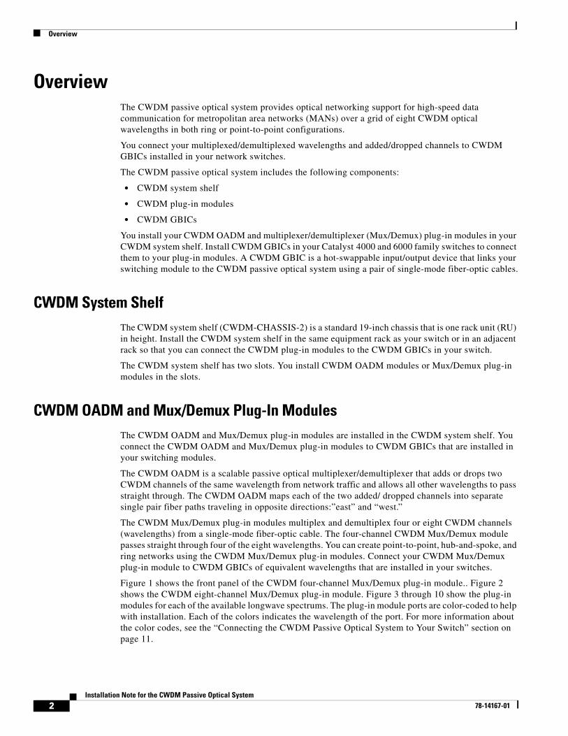
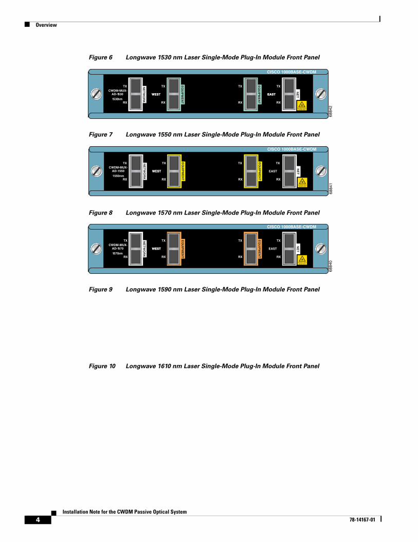
Figure 1 shows the front panel of the CWDM four-channel Mux/Demux plug-in module.. Figure 2 shows the CWDM eight-channel Mux/Demux plug-in module. Figure 3 through 10 show the plug-in modules for each of the available longwave spectrums. The plug-in module ports are color-coded to help with installation. Each of the colors indicates the wavelength of the port. For more information about the color codes, see the “Connecting the CWDM Passive Optical System to Your Switch” section on page 11.
2Installation Note for the CWDM Passive Optical System
78-14167-01
Overview
Figure 1 CWDM Four-Channel Plug-In Module (CWDM-MUX-4) Front Panel
Figure 2 CWDM Eight-Channel Mux/Demux Plug-In Module (CWDM-MUX-8) Front Panel
Figure 3 Longwave 1470 nm Laser Single-Mode Plug-In Module Front Panel
Figure 4 Longwave 1490 nm Laser Single-Mode Plug-In Module Front Panel
Figure 5 Longwave 1510 nm Laser Single-Mode Plug-In Module Front Panel
CISCO 1000BASE-CWDM
6884
6
RX RX
CWDM-MUX- 4
TX TX
1590
1550
1510
1470
PASS
NE
TW
OR
K
INVISIBLE LASERDO NOT VIEW
CISCO 1000BASE-CWDM
6883
7
RX
TX
CWDM-MUX-8
1610
1590
1570
1550
1530
1510
1490
1470
NE
TW
OR
K
INVISIBLE LASERDO NOT VIEW
6884
5
CISCO 1000BASE-CWDM
RX RX RX RX
TX TX TX TX
WESTWEST EAST
NE
TW
OR
K
CWDM-MUX-AD-1470
1470nm
EQ
UIP
ME
NT
EQ
UIP
ME
NT
NE
T
INVISIBLE LASERDO NOT VIEW
CISCO 1000BASE-CWDM
6884
4
RX RX RX RX
TX TX TX TX
WESTWEST EASTEAST
NE
TW
OR
K
CWDM-MUX-AD-1490
1490nm
EQ
UIP
ME
NT
EQ
UIP
ME
NT
NE
T
INVISIBLE LASERDO NOT VIEW
CISCO 1000BASE-CWDM
6884
3
RX RX RX RX
TX TX TX TX
WESTWEST EASTEAST
NE
TW
OR
K
CWDM-MUX-AD-1510
10nm
EQ
UIP
ME
NT
EQ
UIP
ME
NT
NE
T
INVISIBLE LASERDO NOT VIEW
3Installation Note for the CWDM Passive Optical System
78-14167-01
Overview
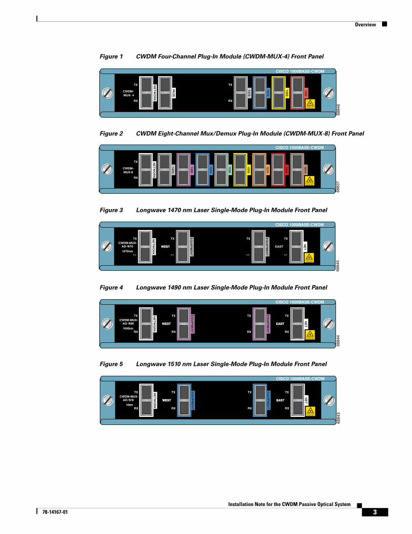
Figure 6 Longwave 1530 nm Laser Single-Mode Plug-In Module Front Panel
Figure 7 Longwave 1550 nm Laser Single-Mode Plug-In Module Front Panel
Figure 8 Longwave 1570 nm Laser Single-Mode Plug-In Module Front Panel
Figure 9 Longwave 1590 nm Laser Single-Mode Plug-In Module Front Panel
Figure 10 Longwave 1610 nm Laser Single-Mode Plug-In Module Front Panel
CISCO 1000BASE-CWDM
6884
2
RX RX RX RX
TX TX TX TX
WESTWEST EASTEAST
NE
TW
OR
K
CWDM-MUX-AD-1530
1530nm
EQ
UIP
ME
NT
EQ
UIP
ME
NT
NE
T
INVISIBLE LASERDO NOT VIEW
CISCO 1000BASE-CWDM
6884
1
CWDM-MUX-AD-1550
1550nmRX RX RX RX
TX TX TXTX
WESTWEST EAST
EQ
UIP
ME
NT
EQ
UIP
ME
NT
NE
T
INVISIBLE LASERDO NOT VIEW
NE
TW
OR
K
CISCO 1000BASE-CWDM
6884
0
NE
TW
OR
K
CWDM-MUX-AD-1570
1570nmRX RX RX RX
TX TX TX TX
WESTWEST EAST
EQ
UIP
ME
NT
EQ
UIP
ME
NT
NE
T
INVISIBLE LASERDO NOT VIEW
4Installation Note for the CWDM Passive Optical System
78-14167-01

Safety Overview
Safety OverviewThroughout this publication, safety warnings appear in procedures that, if performed incorrectly, can harm you. A warning symbol precedes each warning statement.
Warning This warning symbol means danger. You are in a situation that could cause bodily injury. Before you work on any equipment, be aware of the hazards involved with electrical circuitry and be familiar with standard practices for preventing accidents. To see translations of the warnings that appear in this publication, refer to the Regulatory Compliance and Safety Information document that accompanied this device.
Warning WaarschuwingDit waarschuwingssymbool betekent gevaar. U verkeert in een situatie die lichamelijk letsel kan veroorzaken. Voordat u aan enige apparatuur gaat werken, dient u zich bewust te zijn van de bij elektrische schakelingen betrokken risico's en dient u op de hoogte te zijn van standaard maatregelen om ongelukken te voorkomen. Voor vertalingen van de waarschuwingen die in deze publicatie verschijnen, kunt u het document Regulatory Compliance and Safety Information (Informatie over naleving van veiligheids- en andere voorschriften) raadplegen dat bij dit toestel is ingesloten.
Warning VaroitusTämä varoitusmerkki merkitsee vaaraa. Olet tilanteessa, joka voi johtaa ruumiinvammaan. Ennen kuin työskentelet minkään laitteiston parissa, ota selvää sähkökytkentöihin liittyvistä vaaroista ja tavanomaisista onnettomuuksien ehkäisykeinoista. Tässä julkaisussa esiintyvien varoitusten käännökset löydät laitteen mukana olevasta Regulatory Compliance and Safety Information -kirjasesta (määräysten noudattaminen ja tietoa turvallisuudesta).
Warning AttentionCe symbole d'avertissement indique un danger. Vous vous trouvez dans une situation pouvant causer des blessures ou des dommages corporels. Avant de travailler sur un équipement, soyez conscient des dangers posés par les circuits électriques et familiarisez-vous avec les procédures couramment utilisées pour éviter les accidents. Pour prendre connaissance des traductions d’avertissements figurant dans cette publication, consultez le document Regulatory Compliance and Safety Information (Conformité aux règlements et consignes de sécurité) qui accompagne cet appareil.
Warning WarnungDieses Warnsymbol bedeutet Gefahr. Sie befinden sich in einer Situation, die zu einer Körperverletzung führen könnte. Bevor Sie mit der Arbeit an irgendeinem Gerät beginnen, seien Sie sich der mit elektrischen Stromkreisen verbundenen Gefahren und der Standardpraktiken zur Vermeidung von Unfällen bewußt. Übersetzungen der in dieser Veröffentlichung enthaltenen Warnhinweise finden Sie im Dokument Regulatory Compliance and Safety Information (Informationen zu behördlichen Vorschriften und Sicherheit), das zusammen mit diesem Gerät geliefert wurde.
5Installation Note for the CWDM Passive Optical System
78-14167-01
Safety Overview
Warning AvvertenzaQuesto simbolo di avvertenza indica un pericolo. La situazione potrebbe causare infortuni alle persone. Prima di lavorare su qualsiasi apparecchiatura, occorre conoscere i pericoli relativi ai circuiti elettrici ed essere al corrente delle pratiche standard per la prevenzione di incidenti. La traduzione delle avvertenze riportate in questa pubblicazione si trova nel documento Regulatory Compliance and Safety Information (Conformità alle norme e informazioni sulla sicurezza) che accompagna questo dispositivo.
Warning AdvarselDette varselsymbolet betyr fare. Du befinner deg i en situasjon som kan føre til personskade. Før du utfører arbeid på utstyr, må du vare oppmerksom på de faremomentene som elektriske kretser innebærer, samt gjøre deg kjent med vanlig praksis når det gjelder å unngå ulykker. Hvis du vil se oversettelser av deadvarslene som finnes i denne publikasjonen, kan du se i dokumentet Regulatory Compliance and Safety Information (Overholdelse av forskrifter og sikkerhetsinformasjon) som ble levert med denne enheten.
Warning AvisoEste símbolo de aviso indica perigo. Encontra-se numa situação que lhe poderá causar danos físicos. Antes de começar a trabalhar com qualquer equipamento, familiarize-se com os perigos relacionados com circuitos eléctricos, e com quaisquer práticas comuns que possam prevenir possíveis acidentes. Para ver as traduções dos avisos que constam desta publicação, consulte o documento Regulatory Compliance and Safety Information (Informação de Segurança e Disposições Reguladoras) que acompanha este dispositivo.
Warning ¡Advertencia!Este símbolo de aviso significa peligro. Existe riesgo para su integridad física. Antes de manipular cualquier equipo, considerar los riesgos que entraña la corriente eléctrica y familiarizarse con los procedimientos estándar de prevención de accidentes. Para ver una traducción de las advertencias que aparecen en esta publicación, consultar el documento titulado Regulatory Compliance and Safety Information (Información sobre seguridad y conformidad con las disposiciones reglamentarias) que se acompaña con este dispositivo.
Warning Varning!Denna varningssymbol signalerar fara. Du befinner dig i en situation som kan leda till personskada. Innan du utför arbete på någon utrustning måste du varamedveten om farorna med elkretsar och känna till vanligt förfarande för att förebygga skador. Se förklaringar av de varningar som förkommer i denna publikation i dokumentet Regulatory Compliance and Safety Information (Efterrättelse av föreskrifter och säkerhetsinformation), vilket medföljer denna anordning.
Warning Only trained and qualified personnel should be allowed to install or replace this equipment.
6Installation Note for the CWDM Passive Optical System
78-14167-01
Hardware Requirements
Warning Before you install, operate, or service the system, read the Site Preparation and Safety Guide. This guide contains important safety information you should know before working with the system.
Warning Only trained and qualified personnel should be allowed to install, replace, or service this equipment.
Warning Class 1 laser product.
Warning Because invisible laser radiation may be emitted from the aperture of the port when no cable is connected, avoid exposure to laser radiation and do not stare into open apertures.
Warning Ultimate disposal of this product should be handled according to all national laws and regulations.
Warning During this procedure, wear grounding wrist straps to avoid ESD damage to the card. Do not directly touch the backplane with your hand or any metal tool, or you could shock yourself.
Hardware RequirementsYou can use the CWDM passive optical system with Catalyst 4000 and 6000 family switches. Use single-mode fiber-optic cable with SC connectors to connect the CWDM passive optical system to your switches.
Required Tools
Warning During this procedure, wear grounding wrist straps to avoid ESD damage to the card. Do not directly touch the backplane with your hand or any metal tool, or you could shock yourself.
You will need these tools to install the CWDM passive optical system:
• Wrist strap or other grounding device
• Antistatic mat or antistatic foam
• Number 1 and number 2 Phillips screwdrivers for the captive installation screws on most modules
• 3/16-inch flat-blade screwdriver for captive installation screws
7Installation Note for the CWDM Passive Optical System
78-14167-01
Installing the CWDM Passive Optical System
Installing the CWDM Passive Optical SystemThe CWDM passive optical system includes the system shelf, CWDM OADM plug-in modules, CWDM Mux/Demux plug-in modules, and CWDM GBICs.
You must first install the system shelf, then the CWDM OADM and CWDM Mux/Demux plug-in modules, followed by the CWDM GBICs you want to install. The following sections provide the installation procedures for each of these components:
• Installing the System Shelf, page 8
• Installing the CWDM OADM and Mux/Demux Plug-In Modules, page 9
• Removing a CWDM OADM or Mux/Demux Plug-In Module, page 9
• Installing, Removing, and Maintaining CWDM GBICs, page 10
• Connecting the CWDM Passive Optical System to Your Switch, page 11
Installing the System Shelf
Note Ensure that you install the CWDM system shelf in the same rack or an adjacent rack to your Catalyst 4000 family switch so that you can connect all the cables between your CWDM plug-in modules and the CWDM GBICs in your switch.
Follow these steps to mount the system shelf on an equipment rack:
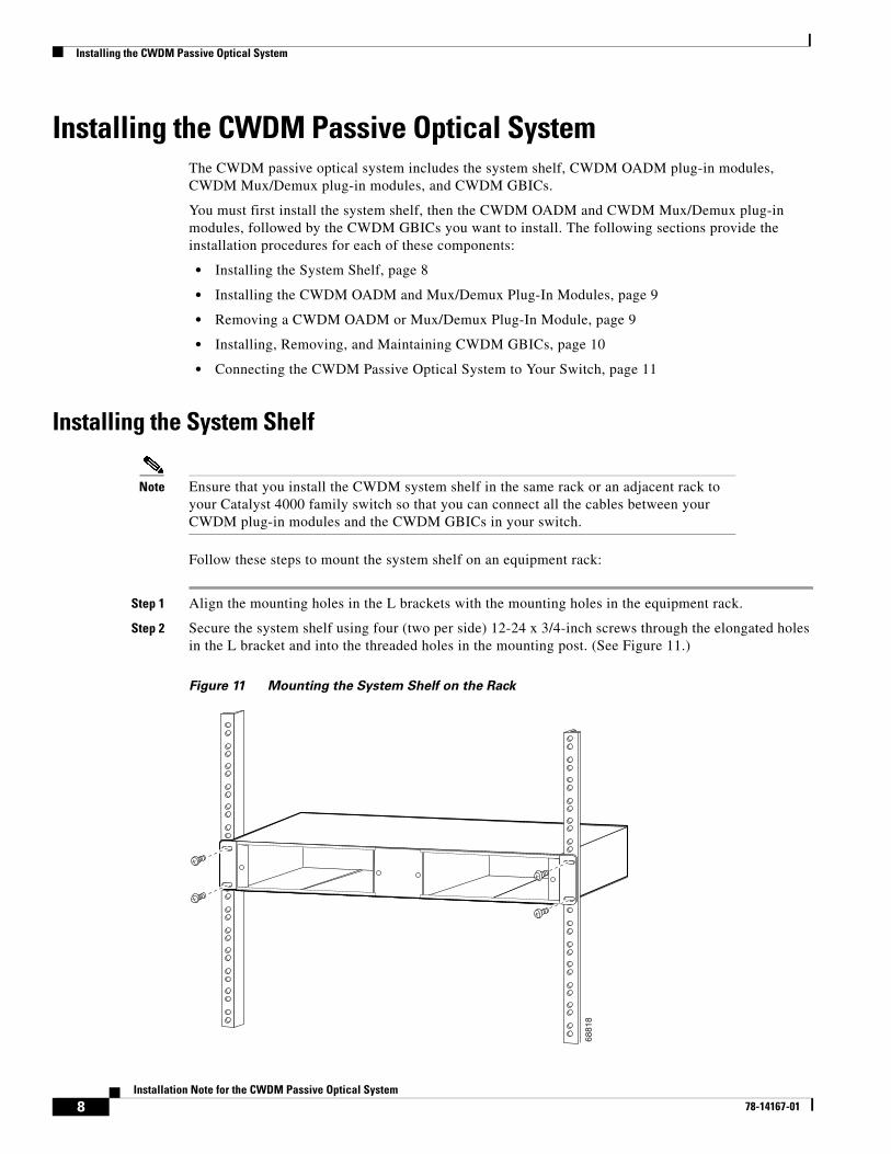
Step 1 Align the mounting holes in the L brackets with the mounting holes in the equipment rack.
Step 2 Secure the system shelf using four (two per side) 12-24 x 3/4-inch screws through the elongated holes in the L bracket and into the threaded holes in the mounting post. (See Figure 11.)
Figure 11 Mounting the System Shelf on the Rack
6881
8
8Installation Note for the CWDM Passive Optical System
78-14167-01
Installing the CWDM Passive Optical System
Step 3 Use a tape measure and level to ensure that the system shelf is mounted straight and level.
Installing the CWDM OADM and Mux/Demux Plug-In ModulesPerform the following steps to install your CWDM OADM or Mux/Demux plug-in modules:
Step 1 Loosen the captive screws on the blank plug-in module faceplate and remove the faceplate.
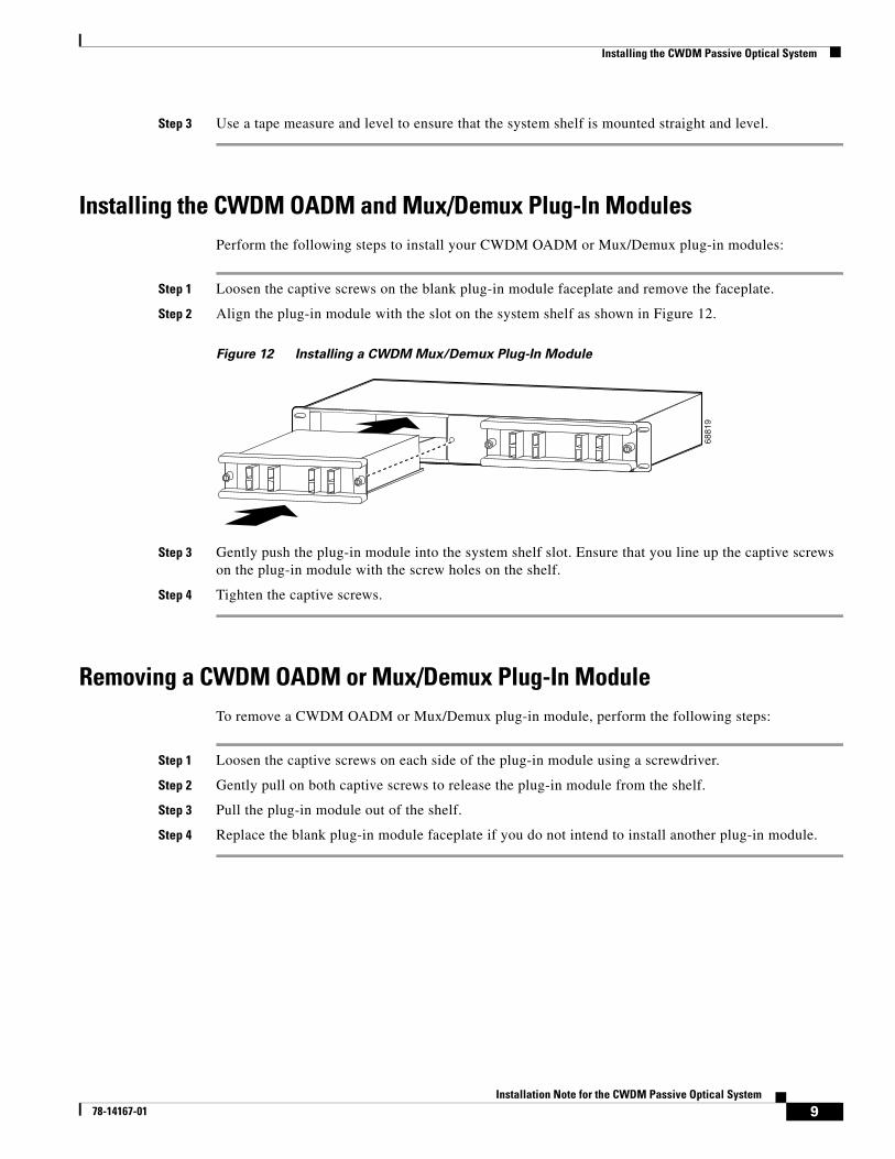
Step 2 Align the plug-in module with the slot on the system shelf as shown in Figure 12.
Figure 12 Installing a CWDM Mux/Demux Plug-In Module
Step 3 Gently push the plug-in module into the system shelf slot. Ensure that you line up the captive screws on the plug-in module with the screw holes on the shelf.
Step 4 Tighten the captive screws.
Removing a CWDM OADM or Mux/Demux Plug-In ModuleTo remove a CWDM OADM or Mux/Demux plug-in module, perform the following steps:
Step 1 Loosen the captive screws on each side of the plug-in module using a screwdriver.
Step 2 Gently pull on both captive screws to release the plug-in module from the shelf.
Step 3 Pull the plug-in module out of the shelf.
Step 4 Replace the blank plug-in module faceplate if you do not intend to install another plug-in module.
6881
9
9Installation Note for the CWDM Passive Optical System
78-14167-01
Installing the CWDM Passive Optical System
Installing, Removing, and Maintaining CWDM GBICsThis section provides installation, removal, and maintenance guidelines for your CWDM GBICs.
Installing a CWDM GBIC
To install a CWDM GBIC, follow these steps:
Step 1 Remove the CWDM GBIC from its protective packaging.
Step 2 Verify that the CWDM GBIC is the correct model for your network configuration (see Table 1).
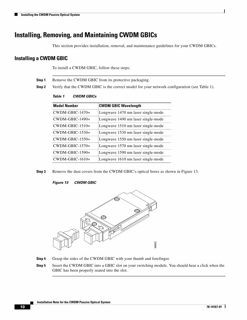
Step 3 Remove the dust covers from the CWDM GBIC’s optical bores as shown in Figure 13.
Figure 13 CWDM GBIC
Step 4 Grasp the sides of the CWDM GBIC with your thumb and forefinger.
Step 5 Insert the CWDM GBIC into a GBIC slot on your switching module. You should hear a click when the GBIC has been properly seated into the slot.
Table 1 CWDM GBICs
Model Number CWDM GBIC Wavelength
CWDM-GBIC-1470= Longwave 1470 nm laser single-mode
CWDM-GBIC-1490= Longwave 1490 nm laser single-mode
CWDM-GBIC-1510= Longwave 1510 nm laser single-mode
CWDM-GBIC-1530= Longwave 1530 nm laser single-mode
CWDM-GBIC-1550= Longwave 1550 nm laser single-mode
CWDM-GBIC-1570= Longwave 1570 nm laser single-mode
CWDM-GBIC-1590= Longwave 1590 nm laser single-mode
CWDM-GBIC-1610= Longwave 1610 nm laser single-mode68
802
10Installation Note for the CWDM Passive Optical System
78-14167-01
Installing the CWDM Passive Optical System
Removing GBICsThis section describes how to remove CWDM GBICs from a supervisor engine or switching module.
Warning Because invisible radiation may be emitted from the aperture of the port when no fiber cable is connected, avoid exposure to radiation and do not stare into open apertures.
To remove a CWDM GBIC, follow these steps:
Step 1 Disconnect the fiber-optic cable from the CWDM GBIC SC-type connector.
Step 2 Release the CWDM GBIC from the slot by simultaneously squeezing the plastic tabs (one on each side of the CWDM GBIC).
Step 3 Pull the CWDM GBIC out of the slot.
Step 4 Install the plug in the CWDM GBIC optical bores and place the CWDM GBIC in protective packaging.
GBIC Maintenance Guidelines
Follow these GBIC maintenance guidelines:
• GBICs are static sensitive. To prevent ESD damage, follow the usual board and component handling procedures.
• GBICs are dust sensitive. When the GBIC is stored or when a fiber-optic cable is not plugged in, always keep plugs in the GBIC optical bores.
• The most common source of contaminants in the optical bores is debris that collects on the ferrules of the optical connectors. Use an alcohol swab or Kim-Wipe to clean the ferrules of the optical connector.
Connecting the CWDM Passive Optical System to Your SwitchUse the CWDM passive optical system connector color codes shown inTable 2 to help you connect your CWDM passive optical system to your switch.
Table 2 CWDM Passive Optical System Connector Color Codes
Color Connector (Wavelength) Descriptions
Gray Longwave 1470 nm laser single-mode
Violet Longwave 1490 nm laser single-mode
Blue Longwave 1510 nm laser single-mode
Green Longwave 1530 nm laser single-mode
Yellow Longwave 1550 nm laser single-mode
Orange Longwave 1570 nm laser single-mode
Red Longwave 1590 nm laser single-mode
Brown Longwave 1610 nm laser single-mode
11Installation Note for the CWDM Passive Optical System
78-14167-01

Installing the CWDM Passive Optical System
See Figure 1 through 10 for the plug-in module front panels. See Table 1 for the CWDM GBIC part numbers and descriptions.
Connecting Cables to a CWDM OADM Plug-In Module
To connect the CWDM OADM plug-in module to your network, perform these steps while referring to Figure 14:
Step 1 Insert the CWDM GBICs into the appropriate connectors on your switch if you have not already done so. For more information, see the “Installing a CWDM GBIC” section on page 10.
Step 2 Insert the CWDM GBICs (color code/wavelength specific) into their respective switching module GBIC ports.
Note Connect CWDM OADM and Mux/Demux ports to CWDM GBICs of the equivalent wavelength to ensure that the system operates correctly.
Step 3 Clean all fiber-optic connectors on the cabling before inserting them into the four-channel CWDM Mux/Demux connectors.
Step 4 Connect the single-mode fiber-optic cable from the CWDM GBIC (TX/RX) to the OADM module equipment connectors (TX/RX).
Note Connect TX to RX ports and RX to TX ports to ensure that the system operates correctly.
Step 5 If you are using both channels of the CWDM OADM plug-in module than repeat Step 4 for the second channel.
Step 6 Connect the West backbone single-mode fiber-optic cable to the OADM Network West connector and connect the East backbone single-mode fiber-optic cable to the OADM Network East connector.
12Installation Note for the CWDM Passive Optical System
78-14167-01

Installing the CWDM Passive Optical System
Figure 14 Cabling a CWDM OADM Plug-In Module
Connecting Cables to a CWDM Four-Channel Plug-In Module
To connect a CWDM four-channel Mux/Demux plug-in module to your network, perform these steps while referring to Figure 15:
Step 1 Insert the CWDM GBICs into the appropriate connectors on your switch if you have not already done so. For more information, see the “Installing a CWDM GBIC” section on page 10.
Step 2 Insert the CWDM GBICs (color code/wavelength specific) into their respective switching module GBIC ports.
Note Connect CWDM OADM and Mux/Demux ports to CWDM GBICs of the equivalent wavelength to ensure that the system operates correctly.
Step 3 Clean all fiber-optic connectors on the cabling before inserting them into the four-channel CWDM Mux/Demux connectors.
Step 4 Connect the single-mode fiber-optic cables from the CWDM GBICs (TX/RX; up to four channels) to the OADM module equipment connectors (TX/RX; up to four wavelengths, including 1470nm, 1510nm, 1550nm, 1590nm).
7336
0
THIS ASSEMBLYCONTAINSELECTROSTATIC-SENSITIVE DEVICES
CAUTION
Power Supply 1
Power Supply 2
Power Supply 3
1
13
1
13
1
13
1
13
1
13
1
13
UPLINK
UPLINK
2UPLINKS ENABLED
CONSOLE
RESET
10/100BASE-TX
1
STATUS
1%
100%
13Installation Note for the CWDM Passive Optical System
78-14167-01
Installing the CWDM Passive Optical System
Note Connect TX to RX ports and RX to TX ports to ensure that the system operates correctly.
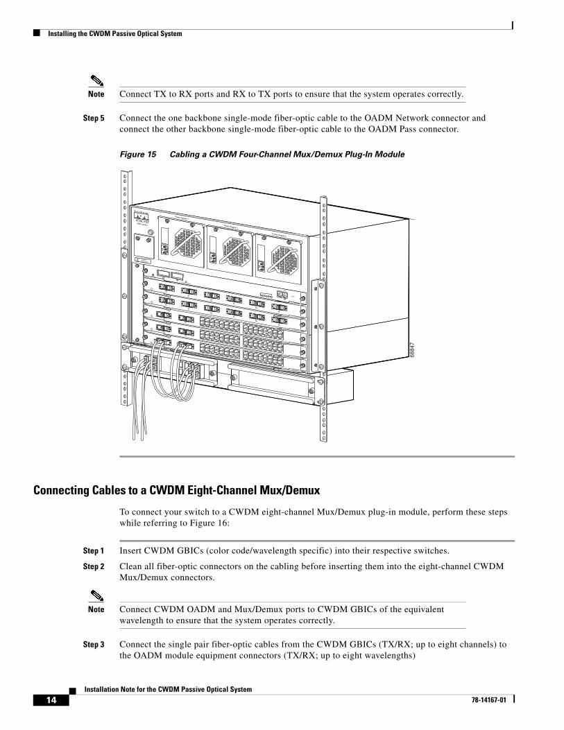
Step 5 Connect the one backbone single-mode fiber-optic cable to the OADM Network connector and connect the other backbone single-mode fiber-optic cable to the OADM Pass connector.
Figure 15 Cabling a CWDM Four-Channel Mux/Demux Plug-In Module
Connecting Cables to a CWDM Eight-Channel Mux/Demux
To connect your switch to a CWDM eight-channel Mux/Demux plug-in module, perform these steps while referring to Figure 16:
Step 1 Insert CWDM GBICs (color code/wavelength specific) into their respective switches.
Step 2 Clean all fiber-optic connectors on the cabling before inserting them into the eight-channel CWDM Mux/Demux connectors.
Note Connect CWDM OADM and Mux/Demux ports to CWDM GBICs of the equivalent wavelength to ensure that the system operates correctly.
Step 3 Connect the single pair fiber-optic cables from the CWDM GBICs (TX/RX; up to eight channels) to the OADM module equipment connectors (TX/RX; up to eight wavelengths)
6884
7
THIS ASSEMBLYCONTAINSELECTROSTATIC-SENSITIVE DEVICES
CAUTION
Power Supply 1
Power Supply 2
Power Supply 3
1
13
1
13
1
13
1
13
1
13
1
13
UPLINK
UPLINK
2UPLINKS ENABLED
CONSOLE
RESET
10/100BASE-TX
1
STATUS
1%
100%
14Installation Note for the CWDM Passive Optical System
78-14167-01
Installing the CWDM Passive Optical System
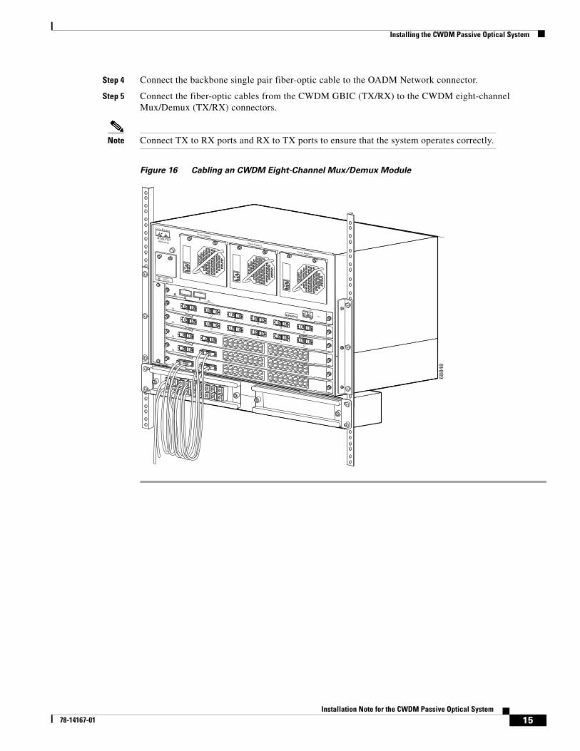
Step 4 Connect the backbone single pair fiber-optic cable to the OADM Network connector.
Step 5 Connect the fiber-optic cables from the CWDM GBIC (TX/RX) to the CWDM eight-channel Mux/Demux (TX/RX) connectors.
Note Connect TX to RX ports and RX to TX ports to ensure that the system operates correctly.
Figure 16 Cabling an CWDM Eight-Channel Mux/Demux Module
6884
8
THIS ASSEMBLYCONTAINSELECTROSTATIC-SENSITIVE DEVICES
CAUTION
Power Supply 1
Power Supply 2
Power Supply 3
1
13
1
13
1
13
1
13
1
13
1
13
UPLINK
UPLINK
2UPLINKS ENABLED
CONSOLE
RESET
10/100BASE-TX
1
STATUS
1%
100%
15Installation Note for the CWDM Passive Optical System
78-14167-01
Specifications
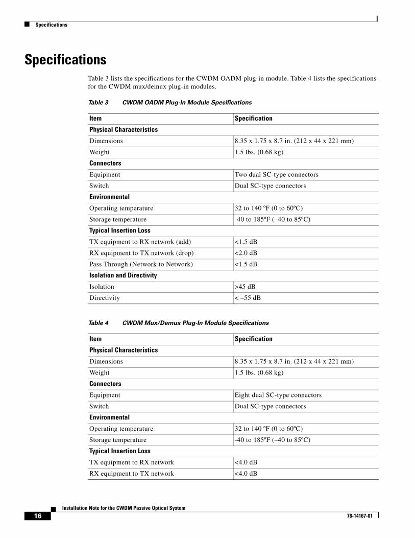
SpecificationsTable 3 lists the specifications for the CWDM OADM plug-in module. Table 4 lists the specifications for the CWDM mux/demux plug-in modules.
Table 3 CWDM OADM Plug-In Module Specifications
Item Specification
Physical Characteristics
Dimensions 8.35 x 1.75 x 8.7 in. (212 x 44 x 221 mm)
Weight 1.5 lbs. (0.68 kg)
Connectors
Equipment Two dual SC-type connectors
Switch Dual SC-type connectors
Environmental
Operating temperature 32 to 140 ºF (0 to 60ºC)
Storage temperature -40 to 185ºF (–40 to 85ºC)
Typical Insertion Loss
TX equipment to RX network (add) <1.5 dB
RX equipment to TX network (drop) <2.0 dB
Pass Through (Network to Network) <1.5 dB
Isolation and Directivity
Isolation >45 dB
Directivity < –55 dB
Table 4 CWDM Mux/Demux Plug-In Module Specifications
Item Specification
Physical Characteristics
Dimensions 8.35 x 1.75 x 8.7 in. (212 x 44 x 221 mm)
Weight 1.5 lbs. (0.68 kg)
Connectors
Equipment Eight dual SC-type connectors
Switch Dual SC-type connectors
Environmental
Operating temperature 32 to 140 ºF (0 to 60ºC)
Storage temperature -40 to 185ºF (–40 to 85ºC)
Typical Insertion Loss
TX equipment to RX network <4.0 dB
RX equipment to TX network <4.0 dB
16Installation Note for the CWDM Passive Optical System
78-14167-01
Related Documentation
Related DocumentationFor more detailed installation and configuration information, refer to these publications:
• Regulatory Compliance and Safety Information for the Catalyst 4000 Family Switches
• Regulatory Compliance and Safety Information for the Catalyst 6000 Family Switches
• Site Preparation and Safety Guide
• Catalyst 4000 Family Installation Guide
• Catalyst 4000 Family Module Installation Guide
• Catalyst 4000 Family Supervisor Engines and Switching Modules Installation Note
• Catalyst 6000 Family Installation Guide
• Catalyst 6000 Family Module Installation Guide
• Software Configuration Guide—Catalyst 4000 Family, Catalyst 2948G, and Catalyst 2980G Switches
• Command Reference—Catalyst 4000 Family, Catalyst 2948G, and Catalyst 2980G Switches
• System Message Guide—Catalyst 6000 Family, Catalyst 5000 Family, Catalyst 4000 Family, Catalyst 2926G Series, Catalyst 2948G, and Catalyst 2980G Switches
• Layer 3 Services Software Configuration Guide—Catalyst 5000 Family, Catalyst 4000 Family, Catalyst 2926G Series, Catalyst 2948G, and Catalyst 2980G Switches
• Catalyst 4000 Family Supervisor Engines and Switching Modules Installation Note
Obtaining DocumentationThe following sections explain how to obtain documentation from Cisco Systems.
World Wide WebYou can access the most current Cisco documentation on the World Wide Web at the following URL:
http://www.cisco.com
Translated documentation is available at the following URL:
http://www.cisco.com/public/countries_languages.shtml
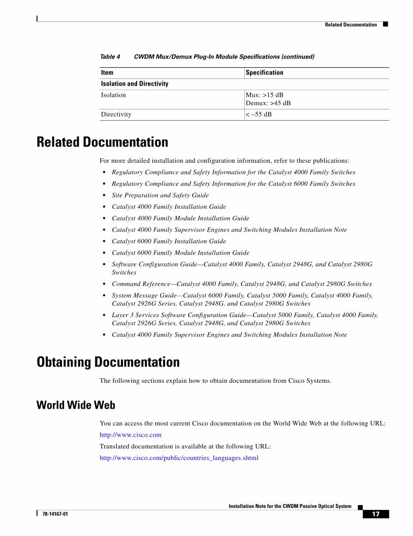
Isolation and Directivity
Isolation Mux: >15 dBDemux: >45 dB
Directivity < –55 dB
Table 4 CWDM Mux/Demux Plug-In Module Specifications (continued)
Item Specification
17Installation Note for the CWDM Passive Optical System
78-14167-01
Obtaining Technical Assistance
Documentation CD-ROMCisco documentation and additional literature are available in a Cisco Documentation CD-ROM package, which is shipped with your product. The Documentation CD-ROM is updated monthly and may be more current than printed documentation. The CD-ROM package is available as a single unit or through an annual subscription.
Ordering DocumentationCisco documentation is available in the following ways:
• Registered Cisco Direct Customers can order Cisco product documentation from the Networking Products MarketPlace:
http://www.cisco.com/cgi-bin/order/order_root.pl
• Registered Cisco.com users can order the Documentation CD-ROM through the online Subscription Store:
http://www.cisco.com/go/subscription
• Nonregistered Cisco.com users can order documentation through a local account representative by calling Cisco corporate headquarters (California, USA) at 408 526-7208 or, elsewhere in North America, by calling 800 553-NETS (6387).
Documentation FeedbackIf you are reading Cisco product documentation on Cisco.com, you can submit technical comments electronically. Click Leave Feedback at the bottom of the Cisco Documentation home page. After you complete the form, print it out and fax it to Cisco at 408 527-0730.
You can e-mail your comments to [email protected].
To submit your comments by mail, use the response card behind the front cover of your document, or write to the following address:
Cisco SystemsAttn: Document Resource Connection170 West Tasman DriveSan Jose, CA 95134-9883
We appreciate your comments.
Obtaining Technical AssistanceCisco provides Cisco.com as a starting point for all technical assistance. Customers and partners can obtain documentation, troubleshooting tips, and sample configurations from online tools by using the Cisco Technical Assistance Center (TAC) Web Site. Cisco.com registered users have complete access to the technical support resources on the Cisco TAC Web Site.
18Installation Note for the CWDM Passive Optical System
78-14167-01
Obtaining Technical Assistance
Cisco.comCisco.com is the foundation of a suite of interactive, networked services that provides immediate, open access to Cisco information, networking solutions, services, programs, and resources at any time, from anywhere in the world.
Cisco.com is a highly integrated Internet application and a powerful, easy-to-use tool that provides a broad range of features and services to help you to
• Streamline business processes and improve productivity
• Resolve technical issues with online support
• Download and test software packages
• Order Cisco learning materials and merchandise
• Register for online skill assessment, training, and certification programs
You can self-register on Cisco.com to obtain customized information and service. To access Cisco.com, go to the following URL:
http://www.cisco.com
Technical Assistance CenterThe Cisco TAC is available to all customers who need technical assistance with a Cisco product, technology, or solution. Two types of support are available through the Cisco TAC: the Cisco TAC Web Site and the Cisco TAC Escalation Center.
Inquiries to Cisco TAC are categorized according to the urgency of the issue:
• Priority level 4 (P4)—You need information or assistance concerning Cisco product capabilities, product installation, or basic product configuration.
• Priority level 3 (P3)—Your network performance is degraded. Network functionality is noticeably impaired, but most business operations continue.
• Priority level 2 (P2)—Your production network is severely degraded, affecting significant aspects of business operations. No workaround is available.
• Priority level 1 (P1)—Your production network is down, and a critical impact to business operations will occur if service is not restored quickly. No workaround is available.
Which Cisco TAC resource you choose is based on the priority of the problem and the conditions of service contracts, when applicable.
Cisco TAC Web Site
The Cisco TAC Web Site allows you to resolve P3 and P4 issues yourself, saving both cost and time. The site provides around-the-clock access to online tools, knowledge bases, and software. To access the Cisco TAC Web Site, go to the following URL:
http://www.cisco.com/tac
All customers, partners, and resellers who have a valid Cisco services contract have complete access to the technical support resources on the Cisco TAC Web Site. The Cisco TAC Web Site requires a Cisco.com login ID and password. If you have a valid service contract but do not have a login ID or password, go to the following URL to register:
http://www.cisco.com/register/
19Installation Note for the CWDM Passive Optical System
78-14167-01
Obtaining Technical Assistance
If you cannot resolve your technical issues by using the Cisco TAC Web Site, and you are a Cisco.com registered user, you can open a case online by using the TAC Case Open tool at the following URL:
http://www.cisco.com/tac/caseopen
If you have Internet access, it is recommended that you open P3 and P4 cases through the Cisco TAC Web Site.
Cisco TAC Escalation Center
The Cisco TAC Escalation Center addresses issues that are classified as priority level 1 or priority level 2; these classifications are assigned when severe network degradation significantly impacts business operations. When you contact the TAC Escalation Center with a P1 or P2 problem, a Cisco TAC engineer will automatically open a case.
To obtain a directory of toll-free Cisco TAC telephone numbers for your country, go to the following URL:
http://www.cisco.com/warp/public/687/Directory/DirTAC.shtml
Before calling, please check with your network operations center to determine the level of Cisco support services to which your company is entitled; for example, SMARTnet, SMARTnet Onsite, or Network Supported Accounts (NSA). In addition, please have available your service agreement number and your product serial number.
This document is to be used in conjunction with the publications described in the “Related Documentation” section on page 17.
AccessPath, AtmDirector, Browse with Me, CCIP, CCSI, CD-PAC, CiscoLink, the Cisco Powered Network logo, Cisco Systems Networking Academy, the Cisco Systems Networking Academy logo, Cisco Unity, Fast Step, Follow Me Browsing, FormShare, FrameShare, IGX, Internet Quotient, IP/VC, iQ Breakthrough, iQ Expertise, iQ FastTrack, the iQ Logo, iQ Net Readiness Scorecard, MGX, the Networkers logo, ScriptBuilder, ScriptShare, SMARTnet, TransPath, Voice LAN, Wavelength Router, and WebViewer are trademarks of Cisco Systems, Inc.; Changing the Way We Work, Live, Play, and Learn, and Discover All That’s Possible are service marks of Cisco Systems, Inc.; and Aironet, ASIST, BPX, Catalyst, CCDA, CCDP, CCIE, CCNA, CCNP, Cisco, the Cisco Certified Internetwork Expert logo, Cisco IOS, the Cisco IOS logo, Cisco Press, Cisco Systems, Cisco Systems Capital, the Cisco Systems logo, Empowering the Internet Generation, Enterprise/Solver, EtherChannel, EtherSwitch, FastHub, FastSwitch, GigaStack, IOS, IP/TV, LightStream, MICA, Network Registrar, Packet, PIX, Post-Routing, Pre-Routing, RateMUX, Registrar, SlideCast, StrataView Plus, Stratm, SwitchProbe, TeleRouter, and VCO are registered trademarks of Cisco Systems, Inc. and/or its affiliates in the U.S. and certain other countries.
All other trademarks mentioned in this document or Web site are the property of their respective owners. The use of the word partner does not imply a partnership relationship between Cisco and any other company. (0110R)
Copyright © 2002, Cisco Systems, Inc.All rights reserved. Printed in USA.
20Installation Note for the CWDM Passive Optical System
78-14167-01