Embed Size (px)
Citation preview
ASCE Geotechnical Engineering Congress 1991 June 10 to 12, 1991, Boulder, Colorado
INSTALLATION OF A GROUT CURTAIN AT A HAZARDOUS WASTE LANDFILL
By
Herff N. Gazaway1, Aff.ASCE; Richard M. Coad2, M.ASCE; and Kenneth B. Andromalos3, M.ASCE
ABSTRACT: An existing inactive hazardous waste landfill located in Niagara Falls, New York was exhibiting migration of contaminants due to lateral groundwater flow in the underlying dolomitic limestone bedrock. It was determined that the installation of a vertical barrier to redirect the groundwater flow around the landfill would be the key element in the abatement design. Further review indicated that a grout curtain would be the most cost-effective method of installing this vertical barrier. The design, which included extensive testing of numerous grout materials for compatibility with known contaminants at the site, required the installation of a single-row grout curtain some eighty feet (26 meters) deep by 2,500 feet (820 meters) long. Slurry grout materials selected and used on this project included fly ash, Types I and V Portland cement, and the largest quantity of ultrafine cement used to date in the United States. All grout injection and verification testing was performed utilizing automated monitoring and recording equipment, facilitating computerized correlation and evaluation of field data. This innovative combination of conventional grout curtain design with the more recent advances in grouting materials and monitoring technology yielded a vertical barrier providing significantly reduced permeability of the underlying bedrock in accordance with the original design objectives. Further, in what may be the largest application of this type to date, this technique appears to be a viable method for control of subsurface contaminant migration in the ever growing hazardous waste management field.
1 – Proj. Mgr., Geo-Con, Inc., P.O. Box 17380, Pittsburgh, PA 15235 2 – Sr. Proj. Engr., Woodward-Clyde Consultants, 512 Butler Pike, Plymouth Meeting, PA 19462 3 – Group Mgr., Geo-Con, Inc. P.O. Box 17380, Pittsburgh, PA 15235
INTRODUCTION For a period of some four decades during the mid-1900s, this site served as a repository for industrial wastes containing various hazardous compounds. Upon discovering similar contaminants in the groundwater beneath and downgradient of the fill area, the Owner closed and capped the site and installed numerous monitoring wells, together with extraction wells on the downgradient side of the site in order to remove and treat the contaminated water as a means of mitigating contaminant migration offsite. The review and analysis of data obtained from this work as well as other investigative work at the site indicated that the primary conduits for contaminant migration in the area were bedding fractures in the underlying bedrock. Further review yielded the concept of a vertical barrier installed on the upgradient sides of the site in order to divert natural groundwater flow around the fill area, thereby improving the containment of offsite contaminant migration and minimizing future groundwater pumping and treatment rates. SOIL/ROCK PROFILE The soil and rock profile at the site consisted of approximately 10 to 20 feet ( 3 to 6 meters) of fill and natural glacial till overlying a nearly horizontally bedded dolomite rock formation. The fill along the grout curtain alignment generally consisted of a silty clay with varying amounts of sand and gravel. Bedrock consisted of a thinly to massively bedded dolomite with core recovery typically in the 90 to 100 percent range. Depending on the degree of fracturing, the Rock Quality Designation (RQD) of the bedrock cored varied from 30 to 100 percent. Within the top 60 to 70 feet (20 to 23 meters) of bedrock, six distinct bedding plane fracture zones were identified. SELECTION OF TREATMENT METHOD AND PROCEDURES Based on the soil/rock profile and previous geotechnical applications, the use of grout curtains was chosen as the method of installing an upgradient vertical barrier on this site. The installation of grout curtains by the injection of cement-based grouts, under pressure, into pervious rock formations is a process which has been used for decades throughout the world to reduce the permeability of these formations. Grout curtains have been utilized primarily as a means of protecting dams by limiting water flow through foundation materials beneath the dam embankment. Where high water head differentials exist on either side of the grout curtain, as in the case of a dam, the grout curtain sometimes may consist of the installation of multiple parallel rows of grout injection holes. The design of the grout curtain on this project was based on current international standards-of-practice for the design of grout curtains, which often involve a single line grout curtain, relatively thick grout mixes, fine grained grouting materials, and
relatively higher injection pressures than are commonly used in the U.S. In addition, the design was based on the general practice of extending the grout curtain into an underlying, relatively impervious stratum. GROUT COMPATIBILITY TESTING As reported by Weaver, et al1, extensive laboratory testing was performed prior to the start of the work in order to assure the compatibility of the proposed grout formulations with the various industrial wastes known to exist at the site. This testing included the use of contaminated water from the site, not only in the preparation of grout mixes, but also as the curing medium for some of the grout samples. This testing yielded the selection of three basic grout formulations: a Type I cement and Class F flyash formulation to be used in relatively open formation conditions, a neat Type V cement grout for use in median conditions, and a neat MC-500 microfine cement grout for relatively tight zones. All of these mixes exhibited final permeabilities ranging from 1 x 10⁻⁹ to 3 x 10⁻¹⁰ cm/sec, thus providing highly acceptable physical properties for the intended application. CONSTRUCTION PROCEDURES The grout curtain was constructed using the single-line, split spacing method. This was accomplished by drilling and grouting vertical holes to form a curtain approximately 2,545 feet (835 meters) long and 80 feet (26 meters) deep. Primary holes were placed on 40 foot (13 meters) centers, with spacings becoming progressively smaller through quaternary holes on 5 foot (1.5 meter) centers. Grout was mixed at mobile batch plants and pumped at controlled pressures through a single pneumatic packer set at various depths in each hole. Each hole was pressure tested and grouted in 10 foot (3 meter) intervals. Figure 1 shows a typical section of the grout curtain. Prior to the initiation of production work, a test section was installed to determine whether descending (down-stage) or ascending (up-stage) grouting methods would be used for production grouting. Results of the test section indicated that the ascending stage grouting method was technically acceptable and more cost effective, thus allowing its selection as the method to be used for the production work.
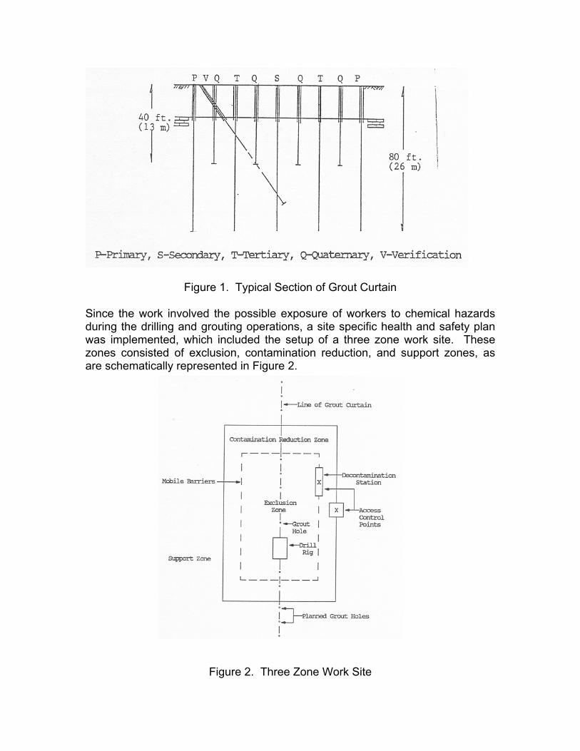
Figure 1. Typical Section of Grout Curtain Since the work involved the possible exposure of workers to chemical hazards during the drilling and grouting operations, a site specific health and safety plan was implemented, which included the setup of a three zone work site. These zones consisted of exclusion, contamination reduction, and support zones, as are schematically represented in Figure 2.
Figure 2. Three Zone Work Site
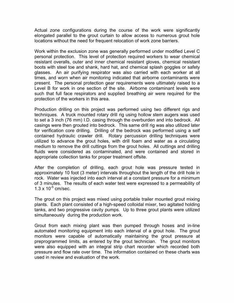
Actual zone configurations during the course of the work were significantly elongated parallel to the grout curtain to allow access to numerous grout hole locations without the need for frequent relocation of work zone barriers. Work within the exclusion zone was generally performed under modified Level C personal protection. This level of protection required workers to wear chemical resistant overalls, outer and inner chemical resistant gloves, chemical resistant boots with steel toe and shank, hard hat, and chemical splash goggles or safety glasses. An air purifying respirator was also carried with each worker at all times, and worn when air monitoring indicated that airborne contaminants were present. The personal protection gear requirements were ultimately raised to a Level B for work in one section of the site. Airborne contaminant levels were such that full face respirators and supplied breathing air were required for the protection of the workers in this area. Production drilling on this project was performed using two different rigs and techniques. A truck mounted rotary drill rig using hollow stem augers was used to set a 3 inch (76 mm) I.D. casing through the overburden and into bedrock. All casings were then grouted into bedrock. This same drill rig was also utilized later for verification core drilling. Drilling of the bedrock was performed using a self contained hydraulic crawler drill. Rotary percussion drilling techniques were utilized to advance the grout holes, with drill foam and water as a circulating medium to remove the drill cuttings from the grout holes. All cuttings and drilling fluids were considered as contaminated, and were contained and stored in appropriate collection tanks for proper treatment offsite. After the completion of drilling, each grout hole was pressure tested in approximately 10 foot (3 meter) intervals throughout the length of the drill hole in rock. Water was injected into each interval at a constant pressure for a minimum of 3 minutes. The results of each water test were expressed to a permeability of 1.3 x 10⁻⁵ cm/sec. The grout on this project was mixed using portable trailer mounted grout mixing plants. Each plant consisted of a high-speed colloidal mixer, two agitated holding tanks, and two progressive cavity pumps. Up to three grout plants were utilized simultaneously during the production work. Grout from each mixing plant was then pumped through hoses and in-line automated monitoring equipment into each interval of a grout hole. The grout monitors were capable of automatically maintaining the grout pressure at preprogrammed limits, as entered by the grout technician. The grout monitors were also equipped with an integral strip chart recorder which recorded both pressure and flow rate over time. The information contained on these charts was used in review and evaluation of the work.
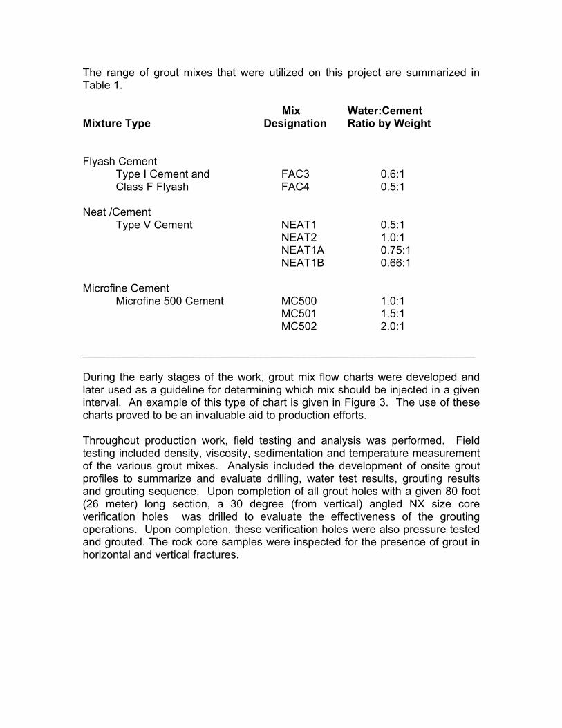
The range of grout mixes that were utilized on this project are summarized in Table 1. Mix Water:Cement Mixture Type Designation Ratio by Weight Flyash Cement Type I Cement and FAC3 0.6:1 Class F Flyash FAC4 0.5:1 Neat /Cement Type V Cement NEAT1 0.5:1 NEAT2 1.0:1 NEAT1A 0.75:1 NEAT1B 0.66:1 Microfine Cement Microfine 500 Cement MC500 1.0:1 MC501 1.5:1 MC502 2.0:1 ________________________________________________________________ During the early stages of the work, grout mix flow charts were developed and later used as a guideline for determining which mix should be injected in a given interval. An example of this type of chart is given in Figure 3. The use of these charts proved to be an invaluable aid to production efforts. Throughout production work, field testing and analysis was performed. Field testing included density, viscosity, sedimentation and temperature measurement of the various grout mixes. Analysis included the development of onsite grout profiles to summarize and evaluate drilling, water test results, grouting results and grouting sequence. Upon completion of all grout holes with a given 80 foot (26 meter) long section, a 30 degree (from vertical) angled NX size core verification holes was drilled to evaluate the effectiveness of the grouting operations. Upon completion, these verification holes were also pressure tested and grouted. The rock core samples were inspected for the presence of grout in horizontal and vertical fractures.
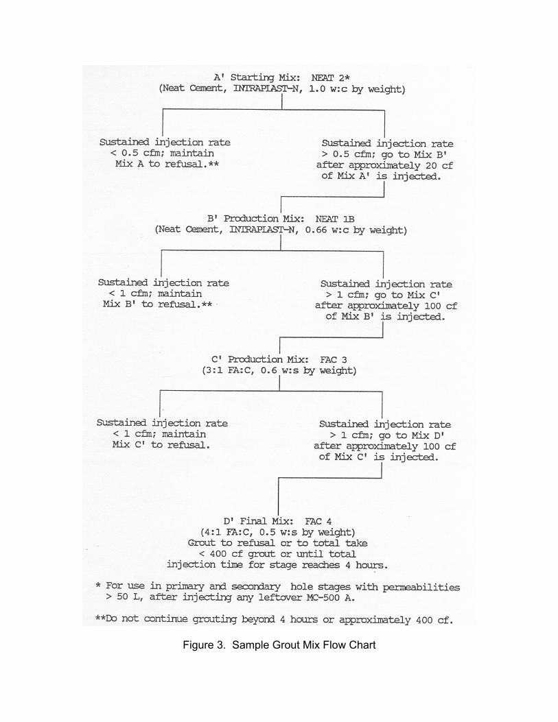
Figure 3. Sample Grout Mix Flow Chart
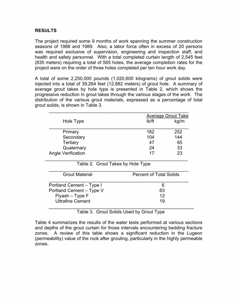
RESULTS The project required some 9 months of work spanning the summer construction seasons of 1988 and 1989. Also, a labor force often in excess of 20 persons was required exclusive of supervision, engineering and inspection staff, and health and safety personnel. With a total completed curtain length of 2,545 feet (835 meters) requiring a total of 565 holes, the average completion rates for the project were on the order of three holes completed per ten hour work day. A total of some 2,250,000 pounds (1,020,600 kilograms) of grout solids were injected into a total of 39,264 feet (12,882 meters) of grout hole. A summary of average grout takes by hole type is presented in Table 2, which shows the progressive reduction in grout takes through the various stages of the work. The distribution of the various grout materials, expressed as a percentage of total grout solids, is shown in Table 3.
______________________________________________________ Average Grout Take
Hole Type lb/ft kg/m ______________________________________________________ Primary 182 252 Secondary 104 144 Tertiary 47 65 Quaternary 24 33 Angle Verification 17 23 _______________________________________________________
Table 2. Grout Takes by Hole Type ______________________________________________________ Grout Material Percent of Total Solids ______________________________________________________ Portland Cement – Type I 6 Portland Cement – Type V 63 Flyash – Type F 12 Ultrafine Cement 19 ________________________________________________________
Table 3. Grout Solids Used by Grout Type
Table 4 summarizes the results of the water tests performed at various sections and depths of the grout curtain for those intervals encountering bedding fracture zones. A review of this table shows a significant reduction in the Lugeon (permeability) value of the rock after grouting, particularly in the highly permeable zones.
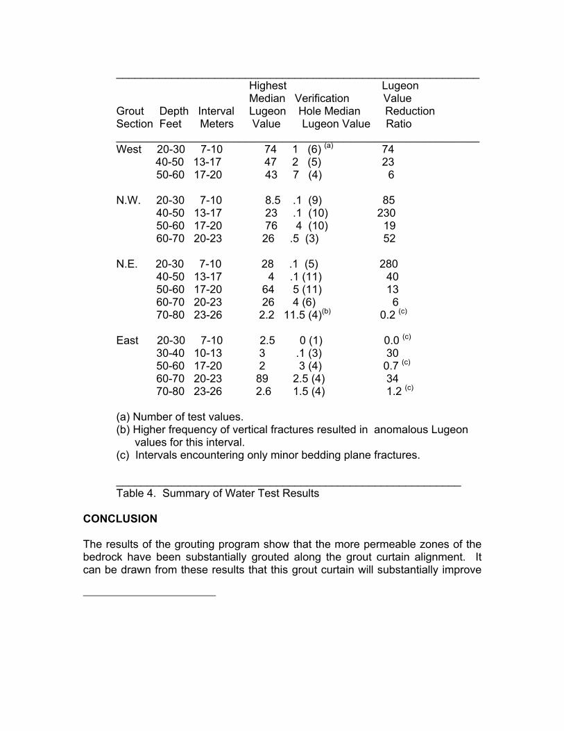
___________________________________________________________ Highest Lugeon Median Verification Value Grout Depth Interval Lugeon Hole Median Reduction Section Feet Meters Value Lugeon Value Ratio ___________________________________________________________ West 20-30 7-10 74 1 (6) (a) 74 40-50 13-17 47 2 (5) 23 50-60 17-20 43 7 (4) 6 N.W. 20-30 7-10 8.5 .1 (9) 85 40-50 13-17 23 .1 (10) 230 50-60 17-20 76 4 (10) 19 60-70 20-23 26 .5 (3) 52 N.E. 20-30 7-10 28 .1 (5) 280 40-50 13-17 4 .1 (11) 40 50-60 17-20 64 5 (11) 13 60-70 20-23 26 4 (6) 6 70-80 23-26 2.2 11.5 (4)(b) 0.2 (c) East 20-30 7-10 2.5 0 (1) 0.0 (c) 30-40 10-13 3 .1 (3) 30 50-60 17-20 2 3 (4) 0.7 (c) 60-70 20-23 89 2.5 (4) 34 70-80 23-26 2.6 1.5 (4) 1.2 (c) (a) Number of test values. (b) Higher frequency of vertical fractures resulted in anomalous Lugeon values for this interval. (c) Intervals encountering only minor bedding plane fractures. ________________________________________________________ Table 4. Summary of Water Test Results
CONCLUSION The results of the grouting program show that the more permeable zones of the bedrock have been substantially grouted along the grout curtain alignment. It can be drawn from these results that this grout curtain will substantially improve
the hydraulic control of the existing groundwater recovery system and reduce the amount of pumping required to effect a hydraulic control of the landfill area. In addition, the improvements and innovations in grout curtain design, equipment, materials, and quality control techniques as used on this project have greatly enhanced the technology of cement grouting in the U.S., such that grout curtains can be relied upon to provide effective control and containment of both nonhazardous and hazardous underground fluids. The use of grout curtains for environmental applications such as this will increase as this vast market continues to develop and technological advancements continue to be made.
REFERENCES
1. KD Weaver, JC Evans & SE Pancoski, Grout Testing for a Hazardous
Waste Application, Concrete International (ACI), July 1990, 45-47.