Embed Size (px)
Citation preview

INSTALLATION OF OPTIC 3-PTV INJECTION SYSTEM INTO
THE SHIMADZU GC-2010 GAS CHROMATOGRAPH
ATAS GL International B.V. Tel: +31 (0)40 254 95 31 Fax: +31 (0)40 254 97 79 Email: [email protected] Internet: www.atasgl.com
Please read this manual before installation!

OPTIC 3-PTV Installation Guide onto Shimadzu GC-2010, OEM Issue 1.1
ATAS GL International B.V. Page 2 of 13
Unpacking the installation kit Check for the following parts in the installation kit.
Description Quantity Part Number
1 OPTIC 3 – Shimatzu GC-2010 Interface Cable 1 H400034
2 SGF (1/16”X0.8X100mm) XX Tubing 1 H400049
3 Shimadzu aluminium packing type-G (pack of 10) 1 H400050

OPTIC 3-PTV Installation Guide onto Shimadzu GC-2010, OEM Issue 1.1
ATAS GL International B.V. Page 3 of 13
Pre-installation
P1. Gases P1.1 A compressed air supply will be required for cooling the OPTIC 3 injector (or for
driving the liquid CO2 cooling valve when a liquid CO2 cooling kit, P/No.H500009, is used).
The compressed air supply should be free of oil, water vapor and particles to ensure
reliable operation of the cooling system. The supply should be made available using 1/8” O.D. tubing. The operating pressure is 500 kPa (72 PSI) and the maximum inlet-pressure is 700 kPa (100 PSI).
P1.2 When OPTIC 3 is to be used with a liquid CO2 sub-ambient kit, please refer to the
CO2 kit installation manual.
P2. Electrical Supply One mains supply socket will be required. OPTIC 3 has a universal electronic power
supply and can be used with 110V (60 Hz) and 230V (50Hz).
P3. Mounting Considerations P3.1 OPTIC 3 Injector Positioning. Shimadzu GC-2010 has several injector positions available. The OPTIC 3 injector will
fit into anyone of these positions. It is advisable to install the injector in the front position when using ATAS GL LINEX option.
P3.2 Control Module Positioning. The OPTIC 3 control module is usually placed on the right hand side of the Shimadzu
GC-2010. The dimensions of the control module are 43cm x 15cm x 43cm (h x w x d).
P4. GC and Autosampler I/O Requirements P4.1 If OPTIC 3 is being mounted on a stand-alone chromatograph a “Cable for OPTIC 3
- Shimadzu GC-2010” is required. (H400013) P4.2 If the GC is equipped with an AOC5000 (CombiPal) autosampler, a “Cable for OPTIC
3 - Shimadzu GC-2010” (H400034) is required and an extra cable between AOC5000 and OPTIC 3 is required. (H400001).
P4.3 If the GC is equipped with the AOC 20i autosampler an additional OPTIC 3 -
Shimadzu AOC 20i Interface Kit (p/no 500025) is required.

OPTIC 3-PTV Installation Guide onto Shimadzu GC-2010, OEM Issue 1.1
ATAS GL International B.V. Page 4 of 13
1. Safety
Before removing any cover from the gas chromatograph!
Disconnect the mains supply;
Disconnect or de-pressurise any gas connections;
Allow all ovens and heated zones to cool to a safe temperature;
Read the relevant sections of the gas chromatograph manual;
2. Removal of Autosampler and/or MS 2.1 If fitted, remove the autosampler and the autosampler mounting plate from the top of
the GC oven, referring to the autosampler and/or GC manuals if required. 2.2 If fitted, the MS may be removed if it obstructs the installation. Refer to the GC and/or
manuals for more information.
3. Removing the inlet
When no free position is available, one of the injectors should be removed. If there is a free position available for the OPTIC 3, skip section 3.
3.1 Turn off the oven and the inlet and allow them to cool down below 50°C.
WARNING: Turn off the oven and the inlet and allow them to cool. Turn off all
flows at the gas supply. Turn off the main power switch and
unplug the power cord.
3.2 Remove the top cover, left side panel and the pneumatics chassis cover.
3.3 Remove the column. 3.4 Loosen the two screws, which secure the inlet to the oven, and lift the inlet out of the oven. 3.5 Remove the heater and the temperature sensor connector. 3.6 Remover the gas line blok attached to the regulator and remove the complete
injector. 3.7 In order to prevent the G.C. reporting an electronic fault condition on the injector
removed above, a replacement plug should be placed.

OPTIC 3-PTV Installation Guide onto Shimadzu GC-2010, OEM Issue 1.1
ATAS GL International B.V. Page 5 of 13
4. Mounting OPTIC 3 Injector
Place the injector in the position prepared and fix it to the GC top using M4x10 screws
supplied with the injector kit (Figure 1).
Figure 1.
5. Gas Control Connections (AFC from GC2010) 5.1 The pipe work from the OPTIC 3 injector should be connected to the filters from the
Shimadzu AFC. 5.2 The injector top should be located and the pipe work uncoiled. 5.3.1 Form the pipe work neatly on the oven top and route the pipe work in such way that it
may be connected to the filters on top of the GC oven.
Figure 2. Solvent Monitor
The solvent monitor should be installed in the split line. It is mounted in a Swagelok tee with PTFE ferrules (Fig. 2). Connect the OPTIC 3 injector split line to the solvent mnitor t-joint (Fig. 3). Connect the second port of the solvent monitor to the Split port of the AFC. Use SGF coupling supplied with the installation kit (p/no H400049).
Solvent Monitor

OPTIC 3-PTV Installation Guide onto Shimadzu GC-2010, OEM Issue 1.1
ATAS GL International B.V. Page 6 of 13
Figure 3.
5.3.2 Connect Split A to Split B. Connect Purge A to Purge B. Connect Carrier A to Carrier B port (Fig. 3).
6. Cooling Air 6.1 Connect the 1/8” O.D. PTFE tube supplied with the injector to the “To Injector” port of
the cooling solenoid valve on the OPTIC 3 rear panel. Cut the PTFE line to the required length and use the rest for the air supply.
6.2 Route the cooling air line to the injector. 6.3. Fit the PTFE tube onto the injector cooling pipe. Take care not to brake the cooling
pipe. 6.4 The PTFE cooling air line can be cut to a required length using a sharp knife to
improve the neatness of the installation. A secure connection will be ensured if the PTFE tube overlaps the cooling pipe by 10-12 mm.
7. Connecting Injector Power and Thermocouple Cables 7.1 Route the injector thermocouple cable under the back cover and of the host
chromatograph. 7.2 Connect the thermocouple plug to the thermocouple socket on the rear panel of the
OPTIC 3 control module. Note that it is important to ensure that the correct connector is used.
WARNING: Do not connect the injector thermocouple to the GC
thermocouple port at the back of the OPTIC controller.
This may permanently damage the injector.

OPTIC 3-PTV Installation Guide onto Shimadzu GC-2010, OEM Issue 1.1
ATAS GL International B.V. Page 7 of 13
Figure 4.
Figure 5. 7.3 Route the power cable (flat blue cable sleeved with a braided fibre sheath) to the
injector ( Fig. 4) and connect the connectors forks as it is shown in Fig. 5 to the injector.
7.4 Secure connections between the power cable and the injector are needed for reliable
operation of the system (torque settings - 5lb/inches [58grms/meter] should be used) Connections that are insufficiently tight will cause increased contact resistance and may cause the connections to overheat. Note, however, that overtightening the power cable fixing screws may cause damage to the threads on the mounting studs which may require replacement of the injector.
8. Connection of Cooling Air Supplies 8.1 Connect a supply of cooling air to the “Air In” port on the solenoid valve on the rear of
the control module at a pressure between 400 to 500 kPa. Lower pressure can be used if decreased cooling performance is acceptable.
9. Connecting OPTIC 3 – GC Interface Cable 9.1 Connect the 15 way D connector of the OPTIC 3 – Shimadzu GC2010 interface cable
(P/No. H400035) to the “Chromatograph” connector on the rear of the OPTIC 3 control module. Connect the other end to the host chromatograph.
Power Cable
Power Cable Connections

OPTIC 3-PTV Installation Guide onto Shimadzu GC-2010, OEM Issue 1.1
ATAS GL International B.V. Page 8 of 13
10. Software Installation (Evolution Workstation) Refer to the OPTIC 3 User‟s Guide Appendix B.
11 . External Communication Configuration Refer to the OPTIC 3 User‟s Guide Appendix B.
12. OPTIC 3 I/O Configuration
The OPTIC 3 I/O configuration should be set via Evolution Workstation software as follows:
OPTIC-GC interface: OPTIC Master;
Ready Out: Disabled Closed;
Ready In: Closed on Ready;
Autosampler output: Closed on Ready; To set the configuration, go to Configuration/System Configuration menu (Fig. 6).
Figure 6.
While within the system configuration dialog, set the options as it is shown in Fig. 7.
Red to 1 Blue to 2 Yellow to 3 Green to 4

OPTIC 3-PTV Installation Guide onto Shimadzu GC-2010, OEM Issue 1.1
ATAS GL International B.V. Page 9 of 13
Figure 7. I/O Settings.
13. Configuration Settings for GC-2010 Shimadzu GC-2010 chromatograph should set the ready output to a closed state when it is in the Ready State. This can be configured via GC local keypad in the following way: press „FUNC” button, go to option 6 – „GC Config‟ and press „Enter‟. Go to option 9 –„Other configurations‟ and press „Enter‟. Set the „Polarity in Ready‟ to „Close‟ (Fig.8).
Figure 8.
14. Configuration for AOC 5000

OPTIC 3-PTV Installation Guide onto Shimadzu GC-2010, OEM Issue 1.1
ATAS GL International B.V. Page 10 of 13
14.1 The best and easiest way to set the configuration of the AOC 5000 is to use the fast-tune file on the CD provided with the OPTIC 3 system. This file has to be „send‟ to the AOC 5000 with the Object Manager application provided on the same CD.
14.2 If the settings to be set manually:
Sync Sginals:
Start signal:
Source: TTL-In1 BlockingTime: 1 sec All other signals should be set to „Immediat‟
Out Signals:
Injected:
Destination: TTL-Out1 PulseTime: 1 sec All other signals should be set to „Off‟
Events: TTL-In1 Active State: Low DebounceTime: 20 msec TTL-In2 Active State: Low DebounceTime: 20 msec TTL-In3 Active State: Low DebounceTime: 20 msec TTL-Out1 Active State: Low Actual State: High TTL-Out2 Active State: High Actual State: Low TTL-Out3 Active State: High Actual State: Low SW-Out1 Active State: On Actual State: Off
SW-Out2 Active State: On Actual State: Off Pwr-Out1 Active State: On Polarity: Pos Low Current: 50 mA High Current: 150 mA High CurTime: 100 msec Actual State: On
15. Testing OPTIC 3 Installation 15.1 Fit an O-ring to a liner and place the liner in the injector, ensuring that the notch at
the end of the liner is towards the bottom of the injector. 15.2 Fit the white PTFE insulating washer to the top of the injector base and screw the
injector top boss to the injector base. Note that excessive tightening of the top boss

OPTIC 3-PTV Installation Guide onto Shimadzu GC-2010, OEM Issue 1.1
ATAS GL International B.V. Page 11 of 13
clamp nut is unnecessary to form a seal between the top and bottom halves of the injector.
15.3 Refit the covers to the host chromatograph, routing the OPTIC 3 cables and pipework
under the injector mouldings and covers if appropriate. Tywraps are provided to allow the cables and pipework to be clipped together to ensure a tidy installation. Refit the injector moulding and cover or autosampler mounting plate.
15.4 Fit a capillary column to the injector and check the pipework for leaks. An electronic
leaktester or 50/50 isopropanol/water should be used for leak checking. Under no circumstances should soap solution or other leak detector fluid be applied to couplings in the piping system.
15.5 Run a test sample of known composition to test the system chromatographically and
to check logic connections between OPTIC 3, host chromatograph and auto sampler, where fitted.
16. Testing the OPTIC 3 I/O communication 16.1 If OPTIC 3 is Master:
The autosampler waits for OPTIC 3 to be ready and OPTIC 3 waits for the GC to be ready. Autosampler starts OPTIC 3, OPTIC 3 starts the GC and the GC starts data-acquisition. To test the communication: Turn the GC oven OFF, set the data-acquisition software to ready, start the AOC5000 method, start an OPTIC 3 method. The AOC5000l should wait, OPTIC 3 should wait (“Wait for Ready In” is shown on the OPTIC 3 display). Turn the GC oven ON. When the GC gets ready signal, OPTIC 3 gets ready signal and the AOC5000 will start.
16.2 When the original Shimadzu autosampler (AOC20I) is used, the same
communication sequence as with a AOC5000 is applied. The installation is now complete.
17. OPTIC 3 LVI method and “GC/GCMS Solutions”
Please read also document: SM-052 Reference Guide, Installation OPTIC 3-PTV on Shimadzu GC-2010 When using an OPTIC 3 LVI method on the system with Shimadzu AFC, a special approach is needed to switch from Split to Splitless mode.
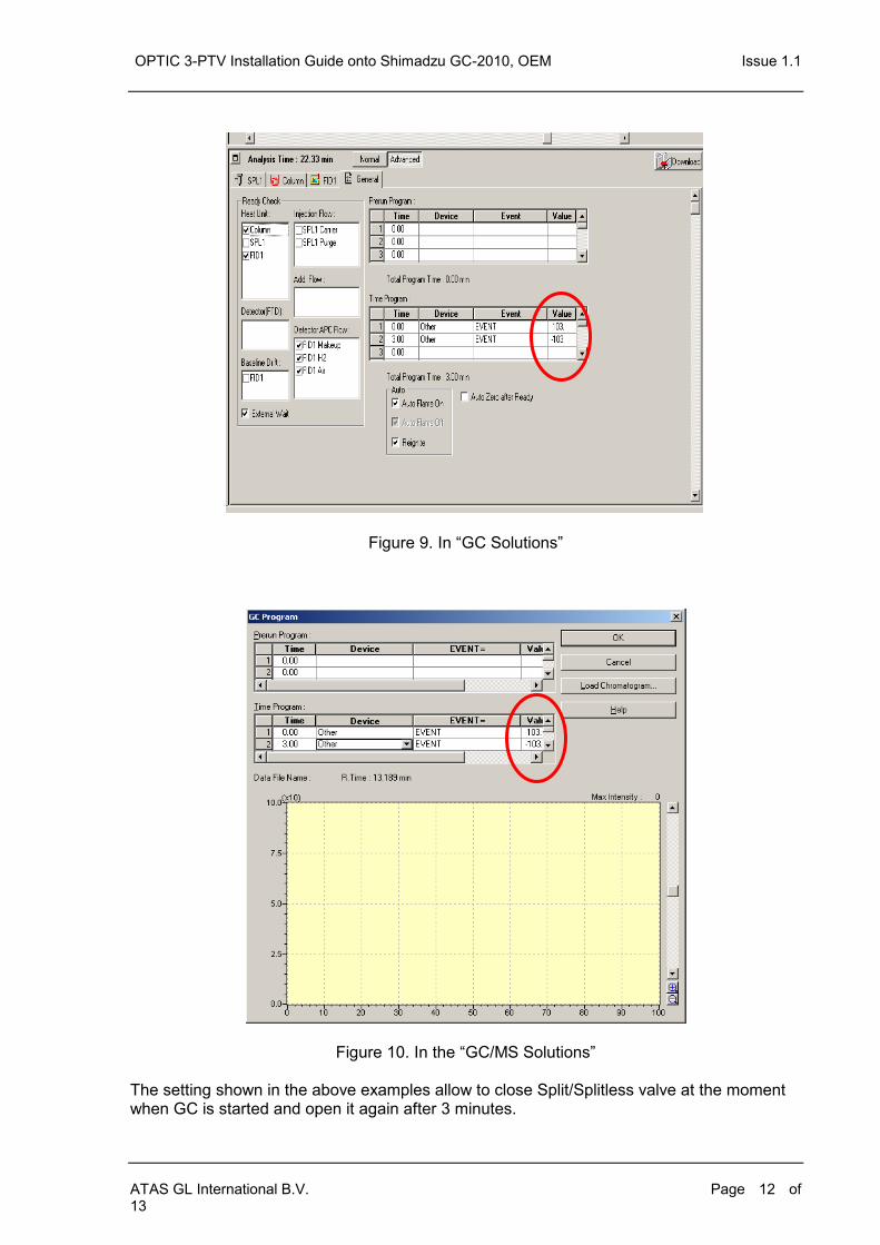
To set the configuration required: go to the tab „General‟ in the GC method window. Program events in the Time Program Table. These events will perform specific tasks that can not be programmed through normal software control.
OPTIC 3-PTV Installation Guide onto Shimadzu GC-2010, OEM Issue 1.1
ATAS GL International B.V. Page 12 of 13
Figure 9. In “GC Solutions”
Figure 10. In the “GC/MS Solutions” The setting shown in the above examples allow to close Split/Splitless valve at the moment when GC is started and open it again after 3 minutes.

OPTIC 3-PTV Installation Guide onto Shimadzu GC-2010, OEM Issue 1.0
ATAS GL International B.V. Page 13 of 13
Shimadzu 2010 OPTIC 3
Remote Bare threads chromatograph 15 pin female 3 TTL Ready out 1 Logic Ready Input
4 Gnd 9 0V
1 Start Start in 7 Relay Run Output
2 Gnd 14 Relay Run Output
Shimadzu GC-2010, Bare Threads, Numbered 1 to 4
OPTIC 3, 15 pin female, „Chromatograph‟
Interface cable for OPTIC 3 – Shimadzu GC-2010 Cable P/No: H400035
1.5 meter, 4 core, shielded