Embed Size (px)
Citation preview

238-
4421
9-00
J R
EV
6/0
9
A
Spa
nish
lang
uage
ver
sion
of t
hese
inst
ruct
ions
is a
vaila
ble
by c
onta
ctin
g th
e co
mpa
ny li
sted
on
the
ratin
g pl
ate.
La
ver
sion
esp
anol
a de
est
as in
stru
ccio
nes
se p
uede
obt
ener
al e
scrib
irle
a la
fabr
ica
cuyo
nom
bre
apar
ece
en la
pla
ca d
e es
peci
ficac
ione
s.
WH
AT
TO D
O IF
YO
U S
MEL
L G
AS
D
o no
t try
to li
ght a
ny a
pplia
nce.
Do
not t
ouch
any
ele
ctric
al s
witc
h; d
o no
t use
any
ph
one
in y
our b
uild
ing.
Imm
edia
tely
cal
l you
r gas
sup
plie
r fro
m a
nei
ghbo
r’s
phon
e. F
ollo
w th
e ga
s su
pplie
r's in
stru
ctio
ns.
If
you
cann
ot re
ach
your
gas
sup
plie
r, ca
ll th
e fir
e
depa
rtm
ent.
Inst
alla
tion
and
serv
ice
mus
t be
perf
orm
ed b
y a
qual
ified
in
stal
ler,
serv
ice
agen
cy o
r the
gas
sup
plie
r. Fo
r you
r fam
ily’s
com
fort
, saf
ety
and
conv
enie
nce,
we
reco
mm
end
this
wat
er h
eate
r be
inst
alle
d an
d se
rvic
ed b
y a
plum
bing
pro
fess
iona
l.
GA
S-FI
RED
WA
TER
HEA
TER
INS
TA
LL
AT
ION
& O
PE
RA
TIN
G IN
ST
RU
CT
ION
M
AN
UA
L F
or
Fla
mm
ab
le V
ap
or
Ign
itio
n R
esi
sta
nt
Sys
tem
Eq
uip
pe
d W
ate
r H
ea
ter
WA
RN
ING
: If
the
info
rmat
ion
in th
ese
inst
ruct
ions
is n
ot
follo
wed
exa
ctly
, a fi
re o
r exp
losi
on m
ay re
sult
caus
ing
prop
erty
dam
age,
per
sona
l inj
ury
or d
eath
.
FOR
YO
UR
SA
FETY
Do
not s
tore
or u
se g
asol
ine
or o
ther
flam
mab
le,
com
bust
ible
, or c
orro
sive
vap
ors
and
liqui
ds in
the
vic
inity
of t
his
or a
ny o
ther
app
lianc
e.

2
CO
NG
RA
TULA
TIO
NS!
Yo
u ha
ve ju
st p
urch
ased
one
of t
he fi
nest
wat
er h
eate
rs o
n th
e m
arke
t to
day!
Th
is in
stal
latio
n, o
pera
tion
and
inst
ruct
ion
man
ual w
ill e
xpla
in in
det
ail
the
inst
alla
tion
and
mai
nten
ance
of y
our n
ew F
lam
mab
le V
apor
Igni
tion
Res
ista
nt G
as W
ater
Hea
ter.
We
stro
ngly
reco
mm
end
that
you
con
tact
a
plum
bing
pro
fess
iona
l for
the
inst
alla
tion
of th
is w
ater
hea
ter.
We
requ
ire th
at y
ou c
aref
ully
read
this
man
ual,
as w
ell a
s th
e en
clos
ed
war
rant
y, a
nd re
fer t
o it
whe
n qu
estio
ns a
rise.
If y
ou h
ave
any
spec
ific
ques
tions
con
cern
ing
your
war
rant
y, p
leas
e co
nsul
t the
plu
mbi
ng
prof
essi
onal
from
who
m y
our w
ater
hea
ter w
as p
urch
ased
. Fo
r you
r re
cord
s w
e re
com
men
d th
at y
ou w
rite
the
mod
el, s
eria
l num
ber a
nd
inst
alla
tion
date
of y
our w
ater
hea
ter i
n th
e m
aint
enan
ce s
ectio
n in
the
back
of t
his
man
ual.
This
man
ual s
houl
d be
kep
t with
the
wat
er h
eate
r.
Spec
ial F
lam
mab
le V
apor
Igni
tion
Res
ista
nt S
yste
m:
This
wat
er h
eate
r is
equi
pped
with
a F
lam
mab
le V
apor
Igni
tion
Res
ista
nt S
yste
m.
In th
e ev
ent o
f im
prop
er u
sage
or s
tora
ge o
f gas
olin
e or
oth
er fl
amm
able
mat
eria
ls
in th
e lo
catio
n w
here
the
wat
er h
eate
r is
inst
alle
d, th
e te
chno
logy
will
resi
st ig
nitio
n of
the
flam
mab
le v
apor
s ou
tsid
e th
e co
nfin
es o
f the
wat
er h
eate
r. Th
e Fl
amm
able
Vap
or Ig
nitio
n R
esis
tant
Sys
tem
feat
ures
:
Adv
ance
d Fl
ame
Arr
esto
r Des
ign.
Re-
setta
ble
Ther
mal
Sw
itch
to p
reve
nt b
urne
r/pilo
t ope
ratio
n w
ith
rest
ricte
d ai
rflow
.
Pie
zo Ig
nite
r
Sig
ht W
indo
w to
obs
erve
ope
ratio
n of
pilo
t and
bur
ner.
FOR
YO
UR
SA
FETY
: Act
ivat
ion
of th
e Fl
amm
able
Vap
or Ig
nitio
n R
esis
tant
S
yste
m o
ccur
s w
hen
flam
mab
le v
apor
s ar
e dr
awn
into
the
wat
er h
eate
r and
are
co
mbu
sted
. If
flam
mab
le v
apor
s ar
e de
tect
ed:
D
o no
t try
to li
ght a
ny a
pplia
nce.
Do
not t
ouch
any
ele
ctric
al s
witc
h; D
o no
t use
any
pho
ne in
you
r bui
ldin
g.
Le
ave
the
prem
ises
and
imm
edia
tely
cal
l the
fire
dep
artm
ent f
rom
a
neig
hbor
’s p
hone
. Fo
llow
the
fire
depa
rtmen
t’s in
stru
ctio
ns.
Onc
e th
e fla
mm
able
vap
or h
as b
een
evac
uate
d, c
onta
ct y
our p
lum
bing
pr
ofes
sion
al o
r the
man
ufac
ture
r for
furth
er in
stru
ctio
ns.
Rep
lace
men
t of a
Fl
amm
able
Vap
or Ig
nitio
n R
esis
tant
Sys
tem
equ
ippe
d w
ater
hea
ter d
ue to
a
flam
mab
le v
apor
shu
tdow
n is
not
cov
ered
und
er th
e te
rms
of th
e lim
ited
war
rant
y.

3
TAB
LE O
F C
ON
TEN
TS
pag
e G
ENER
AL
INFO
RM
ATI
ON
......
......
......
......
......
......
......
......
......
......
4
INST
ALL
ATI
ON
......
......
......
......
......
......
......
......
......
......
......
......
.....
6
Loca
ting
The
Wat
er H
eate
r....
......
......
......
......
......
......
......
......
6
Min
imum
Cle
aran
ces.
......
......
......
......
......
......
......
......
......
......
. 9
Vent
ing.
......
......
......
......
......
......
......
......
......
......
......
......
......
......
10
Com
bust
ion
Air
Supp
ly...
......
......
......
......
......
......
......
......
......
. 1
1
W
ater
Con
nect
ions
......
......
......
......
......
......
......
......
......
......
.....
13
Gas
Con
nect
ions
......
......
......
......
......
......
......
......
......
......
......
.. 1
6 G
ENER
AL
OPE
RA
TIO
N...
......
......
......
......
......
......
......
......
......
......
. 1
7 Li
ghtin
g an
d Sh
utdo
wn
Inst
ruct
ions
......
......
......
......
......
......
18
Ther
mos
tat A
djus
tmen
t....
......
......
......
......
......
......
......
......
.....
20
Bur
ner F
lam
e C
heck
......
......
......
......
......
......
......
......
......
......
...
22
MA
INTE
NA
NC
E...
......
......
......
......
......
......
......
......
......
......
......
......
.. 2
3 TR
OU
BLE
SHO
OTI
NG
......
......
......
......
......
......
......
......
......
......
......
. 26
IN
STA
LLA
TIO
N D
RA
WIN
G F
OR
PO
TAB
LE W
ATE
R...
......
......
...
28
PAR
TS L
IST
DR
AW
ING
......
......
......
......
......
......
......
......
......
......
....
29
PAR
TS L
IST.
......
......
......
......
......
......
......
......
......
......
......
......
......
....
30
INST
ALL
ATI
ON
INST
RU
CTI
ON
S FO
R P
OTA
BLE
WA
TER
AN
D
SPA
CE
HEA
TIN
G...
......
......
......
......
......
......
......
......
......
......
......
.....
31
NO
TES
......
......
......
......
......
......
......
......
......
......
......
......
......
......
......
. 32

4
GEN
ERA
L IN
FOR
MA
TIO
N
This
gas
-fire
d w
ater
hea
ter i
s de
sign
cer
tifie
d by
CS
A In
tern
atio
nal u
nder
the
appl
icab
le A
mer
ican
Nat
iona
l Sta
ndar
d, Z
21.1
0.1
or C
SA
4.1
-(as
indi
cate
d on
th
e ra
ting
plat
e), a
vaila
ble
from
CS
A In
tern
atio
nal,
8501
Eas
t Ple
asan
t Val
ley
Roa
d, C
leve
land
, OH
U.S
.A.
441
31-5
575.
Th
is w
ater
hea
ter m
ust b
e in
stal
led
in a
ccor
danc
e w
ith lo
cal c
odes
. In
the
abse
nce
of lo
cal c
odes
, it m
ust b
e in
stal
led
in c
ompl
ianc
e w
ith th
e N
atio
nal
Fuel
Gas
Cod
e (A
NS
I Z22
3.1-
Late
st E
ditio
n), o
r in
Can
ada
CA
N/C
GA
B14
9.1
Nat
ural
Gas
Inst
alla
tion
Cod
e (L
ates
t Edi
tion)
or C
AN
/CG
A B
149.
2 P
ropa
ne
Inst
alla
tion
Cod
e (L
ates
t Edi
tion)
. Th
e w
arra
nty
for t
his
wat
er h
eate
r is
in
effe
ct o
nly
whe
n th
e w
ater
hea
ter i
s in
stal
led,
adj
uste
d, a
nd o
pera
ted
in
acco
rdan
ce w
ith th
ese
Inst
alla
tion
and
Ope
ratin
g In
stru
ctio
ns.
The
man
ufac
ture
r will
not
be
liabl
e fo
r any
dam
age
resu
lting
from
alte
ratio
n an
d/or
fa
ilure
to c
ompl
y w
ith th
ese
inst
ruct
ions
. Th
is w
ater
hea
ter i
s no
t des
ign
certi
fied
for i
nsta
llatio
n in
a m
obile
hom
e.
Suc
h an
inst
alla
tion
may
cre
ate
a ha
zard
ous
cond
ition
and
will
nul
lify
the
war
rant
y.
This
wat
er h
eate
r has
bee
n de
sign
ed a
nd c
ertif
ied
for t
he p
urpo
se o
f hea
ting
pota
ble
wat
er.
The
inst
alla
tion
and
use
of th
is w
ater
hea
ter f
or a
ny p
urpo
se
othe
r tha
n th
e he
atin
g of
pot
able
wat
er m
ay c
ause
dam
age
to th
e w
ater
he
ater
, cre
ate
a ha
zard
ous
cond
ition
, and
nul
lify
the
war
rant
y.
Do
not u
se th
is a
pplia
nce
if an
y pa
rt ha
s be
en s
ubm
erge
d in
wat
er.
Imm
edia
tely
cal
l a q
ualif
ied
serv
ice
tech
nici
an to
insp
ect t
he a
pplia
nce
and
to
repl
ace
any
part
of th
e co
ntro
l sys
tem
and
any
gas
con
trol,
whi
ch h
as b
een
unde
r wat
er. D
epen
ding
upo
n th
e in
divi
dual
circ
umst
ance
s, it
may
be
nece
ssar
y to
repl
ace
the
entir
e w
ater
hea
ter.
Do
not s
tore
or u
se g
asol
ine
or o
ther
flam
mab
le, c
ombu
stib
le, o
r co
rros
ive
vapo
rs a
nd li
quid
s in
the
vici
nity
of t
his
or a
ny o
ther
ap
plia
nce.
C
AU
TIO
N
Inco
rrec
t ope
ratio
n of
this
app
lianc
e m
ay c
reat
e a
haza
rd to
life
and
pr
oper
ty a
nd w
ill n
ullif
y th
e w
arra
nty.
DA
NG
ER

5
Gen
eral
Info
rmat
ion
cont
inue
d-
This
wat
er h
eate
r has
bee
n m
anuf
actu
red
for o
pera
tion
at a
ltitu
des
from
sea
le
vel t
o 20
00 fe
et (6
10m
) (un
less
oth
erw
ise
spec
ified
on
the
wat
er h
eate
r ra
ting
plat
e).
For u
se o
f thi
s ap
plia
nce
at a
n el
evat
ion
grea
ter t
han
2000
feet
(6
10m
), co
ntac
t the
dea
ler o
r man
ufac
ture
r lis
ted
on th
e ra
ting
plat
e fo
r in
form
atio
n on
any
nec
essa
ry m
odifi
catio
n. U
ncor
rect
ed o
pera
tion
of th
is
appl
ianc
e m
ay c
reat
e a
haza
rd to
life
and
pro
perty
. M
ake
sure
that
you
che
ck th
e ra
ting
plat
e an
d co
mbi
natio
n ga
s co
ntro
l on
the
wat
er h
eate
r to
be c
erta
in th
at th
e ty
pe o
f gas
bei
ng s
uppl
ied
corr
espo
nds
with
the
mar
king
on
the
ratin
g pl
ate
and
com
bina
tion
gas
cont
rol.
A s
acrif
icia
l ano
de is
use
d to
ext
end
tank
life
. The
rem
oval
of t
his
anod
e, fo
r an
y re
ason
, will
nullif
y th
e w
arra
nty.
In a
reas
whe
re w
ater
is u
nusu
ally
act
ive,
an
odo
r may
occ
ur a
t the
hot
wat
er fa
ucet
due
to a
reac
tion
betw
een
the
sacr
ifici
al a
node
and
the
impu
ritie
s in
the
wat
er. I
f thi
s sh
ould
hap
pen,
an
alte
rnat
ive
anod
e m
ay b
e pu
rcha
sed
from
the
supp
lier t
hat i
nsta
lled
this
wat
er
heat
er. T
his
will
min
imiz
e th
e od
or w
hile
pro
tect
ing
the
tank
. Add
ition
ally
, the
w
ater
hea
ter s
houl
d be
flus
hed
with
app
ropr
iate
dis
solv
ers
to e
limin
ate
any
bact
eria
.
IMPO
RTA
NT
Bef
ore
proc
eedi
ng, p
leas
e in
spec
t the
wat
er h
eate
r and
com
pone
nts
for
poss
ible
dam
age.
DO
NO
T in
stal
l any
dam
aged
com
pone
nts.
If d
amag
e is
evi
dent
then
ple
ase
cont
act t
he s
uppl
ier w
here
the
wat
er h
eate
r was
pu
rcha
sed
or th
e m
anuf
actu
rer l
iste
d on
the
ratin
g pl
ate
for r
epla
cem
ent
parts
.

6
INST
ALL
ATI
ON
LO
CA
TIN
G T
HE
WA
TER
HEA
TER
Th
is w
ater
hea
ter M
UST
NO
T be
inst
alle
d in
any
loca
tion
whe
re g
asol
ine
or fl
amm
able
vap
ors
are
likel
y to
be
pres
ent,
unle
ss th
e in
stal
latio
n is
su
ch to
elim
inat
e th
e pr
obab
le ig
nitio
n of
gas
olin
e or
flam
mab
le v
apor
s.
Wat
er h
eate
rs in
resi
dent
ial g
arag
es m
ust b
e in
stal
led
and
loca
ted,
or
prot
ecte
d, to
avo
id p
hysi
cal d
amag
e. F
or o
ther
inst
alla
tions
refe
r to
loca
l cod
es.
In th
e ab
senc
e of
loca
l cod
es, t
he w
ater
hea
ter m
ust b
e in
stal
led
in c
ompl
ianc
e w
ith th
e N
atio
nal F
uel G
as C
ode,
(AN
SI Z
223.
1-
Late
st E
ditio
n), o
r in
Can
ada
CA
N/C
GA
B14
9.1
Nat
ural
Gas
Inst
alla
tion
Cod
e (L
ates
t Edi
tion)
or C
AN
/CG
A B
149.
2 Pr
opan
e In
stal
latio
n C
ode
(Lat
est E
ditio
n).
The
loca
tion
of th
is w
ater
hea
ter i
s of
the
utm
ost i
mpo
rtanc
e. B
efor
e in
stal
ling
this
wat
er h
eate
r rea
d th
e In
stal
latio
n se
ctio
n of
thes
e in
stru
ctio
ns. A
fter
read
ing
thes
e In
stal
latio
n an
d O
pera
ting
Inst
ruct
ions
, sel
ect a
loca
tion
for t
he
wat
er h
eate
r whe
re th
e flo
or is
leve
l and
is e
asily
acc
essi
ble
to g
as a
nd w
ater
su
pply
line
s. D
O N
OT
loca
te th
e w
ater
hea
ter w
here
wat
er li
nes
coul
d be
su
bjec
ted
to fr
eezi
ng te
mpe
ratu
res.
Mak
e su
re th
e co
ld w
ater
pip
es a
re
not l
ocat
ed d
irect
ly a
bove
the
gas
cont
rol s
o th
at c
onde
nsat
e du
ring
hum
id w
eath
er d
oes
not d
rip o
n th
e co
ntro
ls.
This
wat
er h
eate
r MU
ST b
e in
stal
led
indo
ors
out o
f the
win
d an
d w
eath
er.
To c
ompl
y w
ith N
SF
requ
irem
ents
this
wat
er h
eate
r is
to b
e:
a)
Sea
led
to th
e flo
or w
ith s
eala
nt, i
n a
smoo
th a
nd e
asily
cle
anab
le
way
, or
b)
Inst
alle
d w
ith a
n op
tiona
l leg
kit
that
incl
udes
legs
and
/or e
xten
sion
s th
at p
rovi
de a
min
imum
cle
aran
ce o
f 6” b
enea
th th
e w
ater
hea
ter.
W
AR
NIN
G
Wat
er h
eate
rs a
re h
eat p
rodu
cing
app
lianc
es. T
o av
oid
dam
age
or in
jury
th
ere
shal
l be
no m
ater
ials
sto
red
agai
nst t
he w
ater
hea
ter o
r ven
t-air
inta
ke s
yste
m a
nd p
rope
r car
e sh
all b
e ta
ken
to a
void
unn
eces
sary
con
tact
(e
spec
ially
by
child
ren)
with
the
wat
er h
eate
r and
ven
t-air
inta
ke
com
pone
nts.
UN
DER
NO
CIR
CU
MST
AN
CES
SH
ALL
FLA
MM
AB
LE
MA
TER
IALS
, SU
CH
AS
GA
SOLI
NE
OR
PA
INT
THIN
NER
BE
USE
D O
R
STO
RED
IN T
HE
VIC
INIT
Y O
F TH
IS W
ATE
R H
EATE
R, V
ENT-
AIR
IN
TAK
E SY
STEM
OR
IN A
NY
LOC
ATI
ON
FR
OM
WH
ICH
FU
MES
C
OU
LD R
EAC
H T
HE
WA
TER
HEA
TER
OR
VEN
T-A
IR IN
TAK
E SY
STEM
.

7
Inst
alla
tion
(Loc
atin
g Th
e W
ater
Hea
ter)
con
tinue
d-
Not
e: F
or C
alifo
rnia
inst
alla
tion
this
wat
er h
eate
r mus
t be
brac
ed,
anch
ored
, or s
trap
ped
to a
void
falli
ng o
r mov
ing
durin
g an
ear
thqu
ake.
Se
e in
stru
ctio
ns fo
r cor
rect
inst
alla
tion
proc
edur
es.
Inst
ruct
ions
may
be
obta
ined
from
DSA
Hea
dqua
rter
s O
ffice
, 110
2 Q
Str
eet,
Suite
510
0,
Sacr
amen
to, C
A 9
5811
. W
ater
hea
ter c
orro
sion
and
com
pone
nt fa
ilure
can
be
caus
ed b
y th
e he
atin
g an
d br
eakd
own
of a
irbor
ne c
hem
ical
vap
ors.
Exa
mpl
es o
f som
e ty
pica
l co
mpo
unds
that
are
pot
entia
lly c
orro
sive
are
: spr
ay c
an p
rope
llant
s, c
lean
ing
solv
ents
, ref
riger
ator
and
air
cond
ition
ing
refri
gera
nts,
sw
imm
ing
pool
ch
emic
als,
cal
cium
and
sod
ium
chl
orid
e, w
axes
and
pro
cess
che
mic
als.
Th
ese
mat
eria
ls a
re c
orro
sive
at v
ery
low
con
cent
ratio
n le
vels
with
littl
e or
no
odor
to re
veal
thei
r pre
senc
e. N
OTE
: DA
MA
GE
TO T
HE
WA
TER
HEA
TER
C
AU
SED
BY
EXPO
SUR
E TO
CO
RR
OSI
VE V
APO
RS
IS N
OT
CO
VER
ED
BY
THE
WA
RR
AN
TY.
DO
NO
T O
PER
ATE
TH
E W
ATE
R H
EATE
R IF
EX
POSU
RE
HA
S O
R W
ILL
OC
CU
R.
DO
NO
T ST
OR
E A
NY
POTE
NTI
ALL
Y C
OR
RO
SIVE
CO
MPO
UN
DS
IN T
HE
VIC
INIT
Y O
F TH
E W
ATE
R H
EATE
R.
W
AR
NIN
G
Liqu
efie
d pe
trole
um g
ases
/pro
pane
gas
are
hea
vier
than
air
and
will
re
mai
n at
floo
r lev
el if
ther
e is
a le
ak.
Bas
emen
ts, c
raw
l spa
ces,
clo
sets
an
d ar
eas
belo
w g
roun
d le
vel w
ill s
erve
as
pock
ets
for a
ccum
ulat
ion
of
leak
ing
gas.
Bef
ore
light
ing,
sm
ell a
ll ar
ound
the
appl
ianc
e ar
ea fo
r gas
. B
e su
re to
sm
ell n
ext t
o th
e flo
or.
IF Y
OU
SM
ELL
GA
S:
D
o no
t try
to li
ght a
ny a
pplia
nce.
Do
not t
ouch
any
ele
ctric
sw
itch;
do
not u
se a
ny te
leph
one
in y
our
build
ing.
Imm
edia
tely
cal
l you
r gas
sup
plie
r fro
m a
nei
ghbo
r’s te
leph
one.
Fol
low
th
e ga
s su
pplie
r’s in
stru
ctio
ns.
If
you
cann
ot re
ach
your
gas
sup
plie
r, ca
ll th
e fir
e de
partm
ent.
DO
NO
T O
PER
ATE
APP
LIA
NC
E U
NTI
L LE
AK
AG
E IS
CO
RR
ECTE
D!

8
Inst
alla
tion
(Loc
atin
g Th
e W
ater
Hea
ter)
con
tinue
d-
Pro
per v
entin
g pr
actic
es m
ust b
e co
nsid
ered
whe
n se
lect
ing
a lo
catio
n fo
r thi
s w
ater
hea
ter.
For
exa
ct v
entin
g sp
ecifi
catio
ns, p
leas
e co
nsul
t the
Ven
ting
sect
ion
of th
ese
Inst
alla
tion
and
Ope
ratin
g In
stru
ctio
ns.
This
wat
er h
eate
r mus
t be
loca
ted
in a
n ar
ea w
here
leak
age
of th
e ta
nk, w
ater
lin
e co
nnec
tions
, or t
he c
ombi
natio
n te
mpe
ratu
re a
nd p
ress
ure
relie
f val
ve w
ill
not r
esul
t in
dam
age
to th
e ar
ea a
djac
ent t
o th
e w
ater
hea
ter o
r to
low
er fl
oors
of
the
stru
ctur
e. W
hen
such
loca
tions
can
not b
e av
oide
d, a
sui
tabl
e dr
ain
pan
mus
t be
inst
alle
d un
der t
he w
ater
hea
ter.
The
dra
in p
an m
ust h
ave
a m
inim
um le
ngth
and
wid
th o
f at l
east
4 in
. (10
.2 c
m) g
reat
er th
an th
e di
amet
er
of th
e w
ater
hea
ter a
nd m
ust n
ot re
stric
t pro
per c
ombu
stio
n ai
r flo
w to
the
wat
er h
eate
r. T
he d
rain
pan
, as
desc
ribed
abo
ve, c
an b
e pu
rcha
sed
from
yo
ur p
lum
bing
pro
fess
iona
l. T
he d
rain
pan
mus
t be
pipe
d to
an
adeq
uate
dr
ain.
The
pip
ing
mus
t be
at le
ast 3
/4 in
ch (1
.9 c
m) i
n di
amet
er a
nd p
itche
d fo
r pro
per d
rain
age.
It
is re
com
men
ded
that
a m
inim
um c
lear
ance
of f
our (
4) in
ches
(10.
2 cm
) be
prov
ided
on
the
side
of t
he w
ater
hea
ter f
or s
ervi
cing
and
mai
nten
ance
of t
he
com
bina
tion
tem
pera
ture
and
pre
ssur
e re
lief v
alve
.
WA
RN
ING
D
O N
OT
ATT
EMPT
TO
LIG
HT
AN
Y G
AS
APP
LIA
NC
E IF
YO
U A
RE
NO
T C
ERTA
IN O
F TH
E FO
LLO
WIN
G:
Li
quef
ied
petro
leum
gas
es/p
ropa
ne g
as a
nd n
atur
al g
as h
ave
an
odor
ant a
dded
by
the
gas
supp
lier t
hat a
ids
in d
etec
tion
of th
e ga
s.
M
ost p
eopl
e re
cogn
ize
this
odo
r as
a “s
ulfu
r” o
r “ro
tten
egg”
sm
ell.
O
ther
con
ditio
ns, s
uch
as “o
dora
nt fa
de” c
an c
ause
the
odor
ant t
o di
min
ish
in in
tens
ity, o
r “fa
de”,
and
not b
e as
read
ily d
etec
tabl
e.
If
you
have
a d
imin
ishe
d se
nse
of s
mel
l, or
are
in a
ny w
ay u
nsur
e of
th
e pr
esen
ce o
f gas
, im
med
iate
ly c
onta
ct y
our g
as s
uppl
ier f
rom
a
neig
hbor
’s te
leph
one.
Gas
det
ecto
rs a
re a
vaila
ble.
Con
tact
you
r gas
sup
plie
r or p
lum
bing
pr
ofes
sion
al fo
r mor
e in
form
atio
n.

9
MIN
IMU
M C
LEA
RA
NC
ES
W
AR
NIN
G
Failu
re to
adh
ere
to th
ese
inst
alla
tion
and
oper
atin
g in
stru
ctio
ns m
ay
crea
te a
haz
ard
to li
fe a
nd p
rope
rty
and
will
nul
lify
the
war
rant
y.
This
inst
alla
tion
shal
l allo
w a
cces
s to
the
front
of t
he w
ater
hea
ter a
nd
adeq
uate
cle
aran
ce s
hall
be p
rovi
ded
for s
ervi
cing
and
ope
ratin
g th
is w
ater
he
ater
. The
wat
er h
eate
r may
be
inst
alle
d on
eith
er a
com
bust
ible
or n
on-
com
bust
ible
floo
r. If
the
wat
er h
eate
r is
to b
e in
stal
led
dire
ctly
on
carp
etin
g, it
sh
all b
e in
stal
led
on to
p of
a m
etal
or w
ood
pane
l (or
equ
ival
ent)
exte
ndin
g be
yond
the
full
wid
th a
nd d
epth
of t
he a
pplia
nce
by a
t lea
st th
ree
(3) i
nche
s (7
.6 c
m) i
n an
y di
rect
ion
or, i
f the
app
lianc
e is
to b
e in
stal
led
in a
n al
cove
or
clos
et, t
he e
ntire
floo
r sha
ll be
cov
ered
by
the
pane
l. If
the
ratin
g pl
ate
or
the
labe
l on
the
fron
t of t
he h
eate
r spe
cifie
s m
inim
um c
lear
ance
s le
ss
than
thos
e lis
ted
in th
e be
low
tabl
e, th
e w
ater
hea
ter m
ay b
e in
stal
led
in
acco
rdan
ce w
ith th
e m
inim
um c
lear
ance
s lis
ted
on th
e ra
ting
plat
e or
th
e la
bel o
n th
e fr
ont o
f the
hea
ter.
If it
is n
eces
sary
to in
stal
l thi
s w
ater
hea
ter i
n an
alc
ove,
use
the
clea
ranc
es
liste
d in
Fig
ure
1.
Fi
gure
1

10
VEN
TIN
G
This
wat
er h
eate
r has
bee
n sh
ippe
d w
ith a
dra
ft di
verte
r for
whi
ch it
was
de
sign
ed w
ith re
fere
nce
to th
e ho
rizon
tal a
nd v
ertic
al p
lane
s. I
f rem
oved
, the
dr
aft d
iver
ter m
ust b
e re
plac
ed in
the
sam
e po
sitio
n an
d se
cure
d to
the
jack
et
top
by th
e sc
rew
s w
ith w
hich
it w
as in
stal
led.
W
AR
NIN
G
The
vent
ing
syst
em m
ust b
e in
stal
led
prop
erly
follo
win
g al
l loc
al c
odes
or
in
the
abse
nce
of lo
cal c
odes
, the
late
st e
ditio
n of
the
Nat
iona
l Fue
l Gas
Cod
e (A
NS
I Z2
23.1
- la
test
edi
tion)
, or
in C
anad
a, T
he N
atur
al G
as a
nd P
ropa
ne
Inst
alla
tion
Cod
e (B
149.
1-00
lat
est
editi
on).
Fai
lure
to
prop
erly
ins
tall
the
vent
ing
syst
em c
ould
resu
lt in
pro
perty
dam
age,
per
sona
l inj
ury,
or d
eath
.
WA
RN
ING
C
aref
ully
insp
ect t
he v
entin
g sy
stem
of a
repl
acem
ent w
ater
hea
ter
inst
alla
tion
befo
re c
onne
ctin
g to
the
vent
ing
syst
em.
All
join
ts in
the
vent
co
nnec
tor m
ust b
e se
cure
ly fa
sten
ed w
ith s
crew
s an
d fit
tigh
tly to
geth
er.
Insp
ect t
he v
entin
g sy
stem
for s
igns
of d
eter
iora
tion
(rus
t and
per
fora
tion)
an
d re
plac
e an
y se
ctio
ns th
at a
re n
ot in
goo
d co
nditi
on.
The
chim
ney
mus
t be
lined
and
in g
ood
cond
ition
. C
heck
to m
ake
sure
the
vent
ing
syst
em is
pro
perly
siz
ed fo
r the
wat
er h
eate
r. If
the
vent
ing
syst
em
was
pre
viou
sly
size
d fo
r ano
ther
gas
app
lianc
e th
at h
as b
een
rem
oved
, the
ve
ntin
g sy
stem
may
now
be
too
larg
e. R
efer
to th
e la
test
edi
tion
of th
e N
atio
nal F
uel G
as C
ode
(AN
SI Z
223.
1-la
test
edi
tion)
, or i
n C
anad
a, th
e N
atur
al G
as a
nd P
ropa
ne In
stal
latio
n C
ode
(B14
9.1-
00 la
test
edi
tion)
for t
he
corr
ect s
izin
g of
ven
ting
syst
ems
and
com
mon
ven
ting
with
ano
ther
gas
ap
plia
nce.
D
o no
t ven
t thi
s w
ater
hea
ter i
nto
the
vent
ing
syst
em o
f ano
ther
gas
ap
plia
nce
desi
gned
to v
ent u
nder
pos
itive
pre
ssur
e.
The
wat
er h
eate
r sho
uld
be in
stal
led
as c
lose
as
prac
tical
to th
e ve
ntin
g sy
stem
to m
inim
ize
the
vent
con
nect
or le
ngth
requ
ired.
Ref
er to
loca
l cod
es
for t
he d
ista
nce
limita
tions
on
vent
con
nect
or le
ngth
s.
At t
he c
ompl
etio
n of
the
wat
er h
eate
r ins
talla
tion,
the
burn
er a
nd v
entin
g sy
stem
mus
t be
chec
ked
for p
rope
r ope
ratio
n w
ith a
ll ot
her c
omm
only
ve
nted
app
lianc
es in
ope
ratio
n. C
heck
for s
pilla
ge o
f flu
e pr
oduc
ts a
roun
d th
e ou
tsid
e re
lief o
peni
ng o
f the
dra
fthoo
d af
ter s
ever
al m
inut
es o
f op
erat
ion.
The
flam
e fro
m a
mat
ch s
houl
d be
dra
wn
into
the
draf
thoo
d. D
o no
t use
the
wat
er h
eate
r or c
onne
cted
equ
ipm
ent i
f spi
llage
is d
etec
ted
until
th
e pr
oble
m is
cor
rect
ed.
Ref
er to
the
late
st e
ditio
n of
the
Nat
iona
l Fue
l Gas
C
ode,
or i
n C
anad
a, th
e N
atur
al G
as a
nd P
ropa
ne In
stal
latio
n C
ode
for
com
plet
e de
tails
on
the
“Pro
cedu
re to
Be
Follo
wed
to P
lace
Equ
ipm
ent i
n O
pera
tion”
.

11
Vent
ing
cont
inue
d-
This
wat
er h
eate
r mus
t be
conn
ecte
d to
a li
ned
mas
onry
chi
mne
y or
ven
ting
syst
em a
ppro
ved
by lo
cal c
odes
or o
rdin
ance
s. T
he v
ent c
onne
ctor
use
d to
at
tach
the
draf
t div
erte
r out
let t
o th
e ch
imne
y or
app
rove
d ve
nt m
ust b
e of
the
sam
e di
amet
er a
s th
e dr
aft d
iver
ter o
utle
t or l
arge
r. F
or p
rope
r ven
ting
in
certa
in in
stal
latio
ns, a
larg
er v
ent c
onne
ctor
may
be
need
ed.
Con
sult
vent
ing
tabl
es in
AN
SI s
tand
ard
(Z22
3.1-
or la
test
edi
tion)
, Nat
iona
l Fue
l Gas
Cod
e an
d C
AN
/CG
A (B
149.
1 or
B14
9.2-
late
st e
ditio
ns) N
atur
al G
as a
nd P
ropa
ne
Inst
alla
tion
Cod
e, o
r loc
al c
ode
offic
ials
for p
rope
r app
licat
ion
for y
our a
rea.
C
ombu
stio
n A
ir Su
pply
Pro
vide
ade
quat
e ai
r for
com
bust
ion
and
vent
ilatio
n. A
n in
suffi
cien
t sup
ply
of
air w
ill c
ause
reci
rcul
atio
n of
com
bust
ion
prod
ucts
resu
lting
in a
ir co
ntam
inat
ion
that
may
be
haza
rdou
s to
life
. S
uch
a co
nditi
on o
ften
will
resu
lt in
a y
ello
w, l
umin
ous
burn
er fl
ame,
cau
sing
car
boni
ng o
r soo
ting
of th
e co
mbu
stio
n ch
ambe
r, bu
rner
s an
d flu
e tu
bes
with
pos
sibl
e da
mag
e to
the
wat
er h
eate
r. W
hen
an e
xhau
st fa
n is
inst
alle
d in
the
sam
e ro
om w
ith a
hea
ter,
suffi
cien
t op
enin
gs fo
r air
mus
t be
prov
ided
in th
e w
alls
. U
nder
size
d op
enin
gs w
ill
caus
e ai
r to
be d
raw
n in
to th
e ro
om th
roug
h th
e ch
imne
y, c
ausi
ng
reci
rcul
atio
n of
com
bust
ion
prod
ucts
.
WA
RN
ING
Li
quef
ied
petro
leum
gas
es/p
ropa
ne g
as a
re h
eavi
er th
an a
ir an
d w
ill
rem
ain
at fl
oor l
evel
if th
ere
is a
leak
. B
asem
ents
, cra
wl s
pace
s, c
lose
ts
and
area
s be
low
gro
und
leve
l will
ser
ve a
s po
cket
s fo
r acc
umul
atio
n of
le
akin
g ga
s. B
efor
e lig
htin
g, s
mel
l all
arou
nd th
e ap
plia
nce
area
for g
as.
Be
sure
to s
mel
l nex
t to
the
floor
. IF
YO
U S
ME
LL G
AS
:
Do
not t
ry to
ligh
t any
app
lianc
e.
D
o no
t tou
ch a
ny e
lect
ric s
witc
h; d
o no
t use
any
tele
phon
e in
you
r bu
ildin
g.
Im
med
iate
ly c
all y
our g
as s
uppl
ier f
rom
a n
eigh
bor’s
tele
phon
e.
Follo
w th
e ga
s su
pplie
r’s in
stru
ctio
ns.
If
you
cann
ot re
ach
your
gas
sup
plie
r, ca
ll th
e fir
e de
partm
ent.
DO
NO
T O
PER
ATE
APP
LIA
NC
E U
NTI
L LE
AK
AG
E IS
CO
RR
ECTE
D!
IMPO
RTA
NT
The
flow
of c
ombu
stio
n an
d ve
ntila
ting
air m
ust n
ot b
e ob
stru
cted
.
Do
not b
lock
or i
n an
y w
ay re
stric
t jac
ket a
ir in
let s
lots
loca
ted
at th
e bo
ttom
fron
t of t
he w
ater
hea
ter.

12
Com
bust
ion
Air
Supp
ly c
ontin
ued-
C
onfin
ed S
pace
s C
onfin
ed s
pace
s ar
e sp
aces
def
ined
as
havi
ng le
ss th
an 5
0 ft.
3 of s
pace
per
1,
000
BTU
(1.4
1m3 /.2
9kw
) per
hou
r of i
nput
. U
ncon
fined
Spa
ces
In u
ncon
fined
spa
ces
in b
uild
ings
, inf
iltra
tion
may
be
adeq
uate
to p
rovi
de a
ir fo
r com
bust
ion,
ven
tilat
ion
and
dilu
tion
of fl
ue g
ases
. H
owev
er, i
n bu
ildin
gs o
f tig
ht c
onst
ruct
ion
(for e
xam
ple,
wea
ther
stri
ppin
g, h
eavi
ly in
sula
ted,
cau
lked
, va
por b
arrie
r, et
c.),
addi
tiona
l air
may
nee
d to
be
prov
ided
usi
ng th
e m
etho
ds
desc
ribed
abo
ve u
nder
CO
NFI
NE
D S
PA
CE
S:
All
Air
From
Out
door
s or
S
PE
CIA
LLY
EN
GIN
EE
RE
D IN
STA
LLA
TIO
NS
. A
ll A
ir Fr
om In
side
the
Bui
ldin
g: T
he c
onfin
ed s
pace
sha
ll be
pro
vide
d w
ith
two
perm
anen
t ope
ning
s co
mm
unic
atin
g di
rect
ly w
ith a
n ad
ditio
nal r
oom
(s) o
f su
ffici
ent v
olum
e so
that
the
com
bine
d vo
lum
e of
all
spac
es m
eets
the
crite
ria
for a
n un
conf
ined
spa
ce.
The
tota
l inp
ut o
f all
gas
utiliz
atio
n eq
uipm
ent
inst
alle
d in
the
com
bine
d sp
ace
shal
l be
cons
ider
ed in
mak
ing
this
de
term
inat
ion.
Eac
h op
enin
g sh
all h
ave
a m
inim
um fr
ee a
rea
of 1
squ
are
inch
pe
r 100
0 B
TU (6
.45c
m2 /.2
9kw
) per
hou
r of t
he to
tal i
nput
ratin
g of
all
gas
utili
zatio
n eq
uipm
ent i
n th
e co
nfin
ed s
pace
, but
not
less
than
100
squ
are
inch
es (6
45cm
2 ). O
ne o
peni
ng s
hall
be w
ithin
12
inch
es (3
1cm
) of t
he to
p an
d on
e w
ithin
12
inch
es (3
1cm
) of t
he b
otto
m o
f the
enc
losu
re.
All
Air
From
Out
door
s: T
he c
onfin
ed s
pace
sha
ll be
pro
vide
d w
ith tw
o pe
rman
ent o
peni
ngs,
one
com
men
cing
with
in 1
2 in
ches
(31c
m) o
f the
top
and
one
com
men
cing
with
in 1
2 in
ches
(31c
m) f
rom
the
botto
m o
f the
enc
losu
re.
The
open
ings
sha
ll co
mm
unic
ate
dire
ctly
, or b
y du
cts,
with
the
outd
oors
or
spac
es (c
raw
l or a
ttic)
that
free
ly c
omm
unic
ate
with
the
outd
oors
. 1.
W
hen
dire
ctly
com
mun
icat
ing
with
the
outd
oors
, eac
h op
enin
g sh
all h
ave
a m
inim
um fr
ee a
rea
of 1
squ
are
inch
per
400
0 B
TU (6
.45c
m2 /1
.2kw
) per
ho
ur o
f tot
al in
put r
atin
g of
all
equi
pmen
t in
the
encl
osur
e.
2.
Whe
n co
mm
unic
atin
g w
ith th
e ou
tdoo
rs th
roug
h ve
rtica
l duc
ts, e
ach
open
ing
shal
l hav
e a
min
imum
free
are
a of
1 s
quar
e in
ch p
er 4
000
BTU
(6
.45c
m2 /1
.2kw
) per
hou
r of t
otal
inpu
t rat
ing
of a
ll eq
uipm
ent i
n th
e en
clos
ure.
3.
W
hen
com
mun
icat
ing
with
the
outd
oors
thro
ugh
horiz
onta
l duc
ts, e
ach
open
ing
shal
l hav
e a
min
imum
free
are
a of
1 s
quar
e in
ch p
er 2
000
BTU
(6
.45c
m2 /.6
kw) p
er h
our o
f tot
al in
put r
atin
g of
all
equi
pmen
t in
the
encl
osur
e.
4.
Whe
n du
cts
are
used
, the
y sh
all b
e of
the
sam
e cr
oss-
sect
iona
l are
a as
th
e fre
e ar
ea o
f the
ope
ning
s to
whi
ch th
ey c
onne
ct.
The
min
imum
di
men
sion
of r
ecta
ngul
ar a
ir du
cts
shal
l be
not l
ess
than
3 in
ches
(7.5
cm)
Spec
ially
Eng
inee
red
Inst
alla
tions
Th
e re
quire
men
ts n
oted
und
er C
ON
FIN
ED
SP
AC
ES
abo
ve s
hall
not
nece
ssar
ily g
over
n w
hen
spec
ial e
ngin
eerin
g, a
ppro
ved
by th
e au
thor
ity
havi
ng ju
risdi
ctio
n, p
rovi
des
an a
dequ
ate
supp
ly o
f air
for c
ombu
stio
n,
vent
ilatio
n, a
nd d
ilutio
n of
flue
gas
es.

13
WA
TER
CO
NN
ECTI
ON
S N
ote:
BE
FOR
E P
RO
CE
ED
ING
WIT
H T
HE
INS
TALL
ATI
ON
, CLO
SE
TH
E
MA
IN W
ATE
R S
UP
PLY
VA
LVE
. A
fter s
hutti
ng o
ff th
e m
ain
wat
er s
uppl
y, o
pen
a fa
ucet
to re
lieve
the
wat
er li
ne
pres
sure
to p
reve
nt a
ny w
ater
from
leak
ing
out o
f the
pip
es w
hile
mak
ing
the
wat
er c
onne
ctio
ns to
the
wat
er h
eate
r. A
fter t
he p
ress
ure
has
been
relie
ved,
cl
ose
the
fauc
et.
The
CO
LD w
ater
inle
t and
HO
T w
ater
out
let a
re id
entif
ied
on
the
top
of th
e w
ater
hea
ter.
The
fitti
ngs
at th
e co
ld w
ater
inle
t and
hot
wat
er
outle
t are
die
lect
ric w
ater
way
fitti
ngs
with
3/4
” NP
T m
ale
thre
ad.
Mak
e th
e pr
oper
plu
mbi
ng c
onne
ctio
ns b
etw
een
the
wat
er h
eate
r and
the
plum
bing
sy
stem
to th
e ho
use.
Ins
tall
a sh
ut-o
ff va
lve
in th
e co
ld w
ater
sup
ply
line.
If th
is w
ater
hea
ter i
s in
stal
led
in a
clo
sed
wat
er s
uppl
y sy
stem
, suc
h as
the
one
havi
ng a
bac
k-flo
w p
reve
nter
in th
e co
ld w
ater
sup
ply,
pro
visi
ons
shal
l be
mad
e to
con
trol t
herm
al e
xpan
sion
. D
O N
OT
oper
ate
this
wat
er h
eate
r in
a cl
osed
sys
tem
with
out p
rovi
sion
s fo
r con
trolli
ng th
erm
al e
xpan
sion
. Y
our
wat
er s
uppl
ier o
r loc
al p
lum
bing
insp
ecto
r sho
uld
be c
onta
cted
on
how
to
cont
rol t
his
situ
atio
n A
fter i
nsta
llatio
n of
the
wat
er li
nes,
ope
n th
e m
ain
wat
er s
uppl
y va
lve
and
fill
the
wat
er h
eate
r. W
hile
the
wat
er h
eate
r is
fillin
g, o
pen
seve
ral h
ot w
ater
fa
ucet
s to
allo
w a
ir to
esc
ape
from
the
wat
er s
yste
m.
Whe
n a
stea
dy s
tream
of
wat
er fl
ows
thro
ugh
the
fauc
ets,
clo
se th
em a
nd c
heck
all
wat
er
conn
ectio
ns fo
r pos
sibl
e le
aks.
NEV
ER O
PER
ATE
TH
E W
ATE
R H
EATE
R
WIT
HO
UT
FIR
ST B
EIN
G C
ERTA
IN IT
IS F
ILLE
D W
ITH
WA
TER
.
W
AR
NIN
G
FAIL
UR
E TO
INST
ALL
AN
D M
AIN
TAIN
A N
EW, L
ISTE
D 3
/4”
X 3/
4”
TEM
PER
ATU
RE
AN
D P
RES
SUR
E R
ELIE
F VA
LVE
WIL
L R
ELEA
SE T
HE
MA
NU
FAC
TUR
ER F
RO
M A
NY
CLA
IM, W
HIC
H M
IGH
T R
ESU
LT F
RO
M
EXC
ESSI
VE T
EMPE
RA
TUR
E A
ND
PR
ESSU
RES
.
C
AU
TIO
N
If sw
eat f
ittin
gs a
re to
be
use,
DO
NO
T ap
ply
heat
to th
e ni
pple
s on
top
of
the
wat
er h
eate
r. S
wea
t the
tubi
ng to
the
adap
ter b
efor
e fit
ting
the
adap
ter
to th
e w
ater
con
nect
ions
. It
is im
pera
tive
that
hea
t is
not a
pplie
d to
the
nipp
les
cont
aini
ng a
pla
stic
line
r.

14
Inst
alla
tion
(Wat
er C
onne
ctio
ns) c
ontin
ued-
WA
RN
ING
Fo
r pro
tect
ion
agai
nst e
xces
sive
tem
pera
ture
s an
d pr
essu
re, i
nsta
ll te
mpe
ratu
re a
nd p
ress
ure
prot
ectiv
e eq
uipm
ent r
equi
red
by lo
cal c
odes
, bu
t not
less
than
a c
ombi
natio
n te
mpe
ratu
re a
nd p
ress
ure
relie
f val
ve
certi
fied
by a
nat
iona
lly re
cogn
ized
test
ing
labo
rato
ry th
at m
aint
ains
pe
riodi
c in
spec
tion
of p
rodu
ctio
n of
list
ed e
quip
men
t or m
ater
ials
as
mee
ting
the
requ
irem
ents
of t
he S
tand
ard
for R
elie
f Val
ves
and
Aut
omat
ic
Gas
Shu
toff
Dev
ices
for H
ot W
ater
Sup
ply
Sys
tem
s, A
NS
I Z21
.22
or th
e S
tand
ard
CA
N1-
4.4.
Tem
pera
ture
and
Pre
ssur
e an
d th
e S
tand
ard
CA
N1-
4.4,
Tem
pera
ture
, Pre
ssur
e, T
empe
ratu
re a
nd P
ress
ure
Rel
ief V
alve
s an
d V
acuu
m R
elie
f Val
ves.
The
com
bina
tion
tem
pera
ture
and
pre
ssur
e re
lief
valv
e sh
all b
e m
arke
d w
ith a
max
imum
set
pre
ssur
e no
t to
exce
ed th
e m
axim
um w
orki
ng p
ress
ure
of th
e w
ater
hea
ter.
The
com
bina
tion
tem
pera
ture
and
pre
ssur
e re
lief v
alve
sha
ll al
so h
ave
an h
ourly
rate
d te
mpe
ratu
re s
team
BTU
dis
char
ge c
apac
ity n
ot le
ss th
an th
e ho
urly
ratin
g of
the
wat
er h
eate
r.
Inst
all t
he c
ombi
natio
n te
mpe
ratu
re a
nd p
ress
ure
relie
f val
ve in
to th
e op
enin
g pr
ovid
ed a
nd m
arke
d fo
r thi
s pu
rpos
e on
the
wat
er h
eate
r.
Not
e: S
ome
mod
els
may
alre
ady
be e
quip
ped
or s
uppl
ied
with
a
com
bina
tion
tem
pera
ture
and
pre
ssur
e re
lief v
alve
. V
erify
that
the
com
bina
tion
tem
pera
ture
and
pre
ssur
e re
lief v
alve
com
plie
s w
ith lo
cal
code
s. I
f the
com
bina
tion
tem
pera
ture
and
pre
ssur
e re
lief v
alve
doe
s no
t co
mpl
y w
ith lo
cal c
odes
, rep
lace
it w
ith o
ne th
at d
oes.
Fol
low
the
inst
alla
tion
inst
ruct
ions
abo
ve o
n th
is p
age.
Inst
all a
dis
char
ge li
ne s
o th
at w
ater
dis
char
ged
from
the
com
bina
tion
tem
pera
ture
and
pre
ssur
e re
lief v
alve
will
exi
t with
in s
ix (6
) inc
hes
(15.
2 cm
) abo
ve, o
r any
dis
tanc
e be
low
the
stru
ctur
al fl
oor a
nd c
anno
t con
tact
an
y liv
e el
ectri
cal p
art.
The
disc
harg
e lin
e is
to b
e in
stal
led
to a
llow
for
com
plet
e dr
aina
ge o
f bot
h th
e co
mbi
natio
n te
mpe
ratu
re a
nd p
ress
ure
relie
f val
ve a
nd th
e di
scha
rge
line.
The
dis
char
ge o
peni
ng m
ust n
ot b
e su
bjec
ted
to b
lock
age
or fr
eezi
ng.
DO
NO
T th
read
, plu
g or
cap
the
disc
harg
e lin
e. I
t is
reco
mm
ende
d th
at a
min
imum
cle
aran
ce o
f fou
r (4)
in
ches
(10.
2 cm
) be
prov
ided
on
the
side
of t
he w
ater
hea
ter f
or s
ervi
cing
an
d m
aint
enan
ce o
f the
com
bina
tion
tem
pera
ture
and
pre
ssur
e re
lief
valv
e.
D
o no
t pla
ce a
val
ve b
etw
een
the
com
bina
tion
tem
pera
ture
and
pre
ssur
e re
lief v
alve
and
the
tank
.

15
Inst
alla
tion
(Wat
er C
onne
ctio
ns) c
ontin
ued-
This
wat
er h
eate
r can
del
iver
sca
ldin
g te
mpe
ratu
re w
ater
at a
ny fa
ucet
in th
e sy
stem
. B
e ca
refu
l whe
neve
r usi
ng h
ot w
ater
to a
void
sca
ldin
g in
jury
. C
erta
in
appl
ianc
es s
uch
as d
ishw
ashe
rs a
nd a
utom
atic
clo
thes
was
hers
may
requ
ire
incr
ease
d te
mpe
ratu
re w
ater
. B
y se
tting
the
ther
mos
tat o
n th
is w
ater
hea
ter
to o
btai
n th
e in
crea
sed
tem
pera
ture
wat
er re
quire
d by
thes
e ap
plia
nces
, the
po
tent
ial f
or s
cald
inju
ry in
crea
ses.
To
prot
ect a
gain
st in
jury
, you
sho
uld
inst
all a
n A
SS
E a
ppro
ved
mix
ing
valv
e in
the
wat
er s
yste
m.
This
val
ve w
ill re
duce
poi
nt o
f dis
char
ge te
mpe
ratu
re b
y m
ixin
g co
ld a
nd h
ot w
ater
in b
ranc
h su
pply
line
s. S
uch
valv
es a
re a
vaila
ble
from
the
man
ufac
ture
r of t
his
wat
er
heat
er o
r a lo
cal p
lum
bing
sup
plie
r. P
leas
e co
nsul
t with
a p
lum
bing
pr
ofes
sion
al.
APP
RO
XIM
ATE
TIM
E/TE
MPE
RA
TUR
E R
ELA
TIO
NSH
IPS
IN S
CA
LDS
120°
F (4
9°C
) M
ore
than
5 m
inut
es
125°
F (5
2°C
) 1½
to 2
min
utes
13
0°F
(54°
C)
Abo
ut 3
0 se
cond
s 13
5°F
(57°
C)
Abo
ut 1
0 se
cond
s 14
0°F
(60°
C)
Less
than
5 s
econ
ds
145°
F (6
3°C
) Le
ss th
an 3
sec
onds
15
0°F
(66°
C)
Abo
ut 1
½ s
econ
ds
155°
F (6
8°C
) A
bout
1 s
econ
d
W
AR
NIN
G
Hyd
roge
n ga
s ca
n be
pro
duce
d in
an
oper
atin
g w
ater
hea
ter t
hat h
as
not h
ad w
ater
dra
wn
from
the
tank
for a
long
per
iod
of ti
me
(gen
eral
ly
two
wee
ks o
r mor
e).
Hyd
roge
n ga
s is
ext
rem
ely
flam
mab
le.
To
prev
ent t
he p
ossi
bilit
y of
inju
ry u
nder
thes
e co
nditi
ons,
we
reco
mm
end
the
hot w
ater
fauc
et to
be
open
for s
ever
al m
inut
es a
t the
ki
tche
n si
nk b
efor
e yo
u us
e an
y el
ectr
ical
app
lianc
e, w
hich
is
conn
ecte
d to
the
hot w
ater
sys
tem
. If
hydr
ogen
is p
rese
nt, t
here
will
be
an
unus
ual s
ound
suc
h as
air
esca
ping
thro
ugh
the
pipe
s as
hot
w
ater
beg
ins
to fl
ow.
Do
not s
mok
e or
hav
e op
en fl
ame
near
the
fauc
et a
t the
tim
e it
is o
pen.

16
Gas
Con
nect
ions
Th
e ga
s su
pply
line
s m
ust m
eet a
ll re
quire
men
ts o
f the
Nat
iona
l Fue
l Gas
Cod
e (A
NS
I Z2
23.1
-Lat
est E
ditio
n), o
r in
Can
ada
CA
N/C
GA
B14
9.1
Nat
ural
Gas
Inst
alla
tion
Cod
e (L
ates
t Edi
tion)
or C
AN
/CG
A B
149.
2 P
ropa
ne In
stal
latio
n C
ode
(Lat
est E
ditio
n).
The
min
imum
per
mis
sibl
e ga
s su
pply
pre
ssur
e fo
r the
pur
pose
of i
nput
adj
ustm
ent i
s on
e (1
.0) i
nch
(0.2
5 kP
a) w
ater
col
umn
abov
e th
e op
erat
ing
man
ifold
pre
ssur
e. S
ee
the
ratin
g pl
ate
and
gas
valv
e fo
r the
man
ifold
pre
ssur
e an
d ga
s ty
pe.
The
max
imum
pe
rmis
sibl
e ga
s su
pply
pre
ssur
e is
four
teen
(14.
0) in
ches
(3.5
kP
a) w
ater
col
umn
for
natu
ral g
as a
nd li
quef
ied
petro
leum
gas
es/p
ropa
ne g
as.
1.
Con
nect
this
wat
er h
eate
r onl
y to
the
type
of g
as (N
atur
al o
r Pro
pane
gas
) as
show
n on
the
ratin
g pl
ate.
Use
cle
an b
lack
iron
pip
e or
equ
ival
ent m
ater
ial
appr
oved
by
loca
l cod
es a
nd o
rdin
ance
s. (D
irt a
nd s
cale
from
the
pipe
can
ent
er
the
gas
valv
e an
d ca
use
it to
mal
func
tion)
. Th
e in
let g
as li
ne m
ust h
ave
a m
inim
um le
ngth
of t
hree
(3) i
nche
s (7
.6 c
m) d
rip le
g (s
edim
ent t
rap)
inst
alle
d as
cl
ose
to th
e w
ater
hea
ter’s
gas
val
ve a
s po
ssib
le.
A g
roun
d jo
int u
nion
mus
t be
inst
alle
d as
clo
se to
the
wat
er h
eate
r as
poss
ible
in th
e ga
s su
pply
line
feed
ing
the
wat
er h
eate
r to
perm
it se
rvic
ing
of th
e w
ater
hea
ter.
Com
poun
ds u
sed
on th
e th
read
ed jo
ints
of t
he g
as p
ipin
g m
ust b
e re
sist
ant t
o th
e ac
tion
of li
quef
ied
petro
leum
gas
es/p
ropa
ne g
as.
DO
NO
T ap
ply
pipe
dop
e to
the
gas
valv
e in
let a
nd
mak
e ce
rtain
that
no
pipe
dop
e ha
s be
com
e lo
dged
in th
e in
let s
cree
n of
the
gas
valv
e. E
xtre
me
care
mus
t be
take
n to
ens
ure
no p
ipe
dope
ent
ers
the
gas
valv
e.
Avo
id e
xces
sive
torq
ue w
hen
tight
enin
g th
e ga
s su
pply
line
to th
e ga
s va
lve.
E
xces
sive
torq
ue m
ay re
sult
in c
rack
ing
of th
e ga
s va
lve
hous
ing
and
coul
d cr
eate
a
gas
leak
. W
hen
tight
enin
g ga
s su
pply
line
to L
.P. c
ontro
l, it
is re
com
men
ded
to
hold
the
inle
t bod
y of
the
cont
rol s
ecur
ely
with
an
adeq
uate
wre
nch.
The
su
gges
ted
max
imum
torq
ue is
31.
5 ft.
lbs.
(4.4
kg-
m).
2.
This
wat
er h
eate
r and
its
gas
conn
ectio
n m
ust b
e le
ak te
sted
bef
ore
plac
ing
the
wat
er h
eate
r in
oper
atio
n. C
heck
for g
as le
aks
with
a s
oap
and
wat
er s
olut
ion
and
a br
ush
or a
com
mer
cial
leak
det
ecto
r flu
id. N
EVER
USE
A M
ATC
H O
R O
PEN
FL
AME
FOR
TES
TIN
G!
3.
Whi
le c
heck
ing
for l
eaks
car
e m
ust b
e ta
ken
to p
reve
nt s
olut
ion
from
co
ntac
ting
the
elec
trica
l con
nect
ions
at t
he c
ontro
l. If
elec
trica
l con
nect
ions
at t
he
cont
rol b
ecom
e w
et, t
hey
mus
t be
thor
ough
ly d
ried
befo
re a
ttem
ptin
g to
ope
rate
th
e w
ater
hea
ter.
W
AR
NIN
G
The
man
ufac
ture
r of t
his
wat
er h
eate
r will
not b
e lia
ble
for a
ny d
amag
e or
inju
ry
caus
ed a
s a
resu
lt of
a c
rack
ed g
as in
let a
s a
resu
lt of
exc
essi
ve to
rque
.
C
AU
TIO
N
The
wat
er h
eate
r and
indi
vidu
al s
huto
ff va
lve
mus
t be
disc
onne
cted
from
the
gas
supp
ly p
ipin
g sy
stem
dur
ing
any
pres
sure
test
ing
of th
e sy
stem
at t
est p
ress
ures
in
exce
ss o
f 1/2
psi
(3.5
kP
a).
The
wat
er h
eate
r mus
t be
isol
ated
from
the
gas
supp
ly
pipi
ng s
yste
m b
y cl
osin
g its
man
ual s
huto
ff va
lve
durin
g an
y pr
essu
re te
stin
g of
the
gas
supp
ly s
yste
m a
t tes
t pre
ssur
es e
qual
to o
r les
s th
an 1
/2 p
si (3
.5 k
Pa)
. Th
e su
pply
line
mus
t be
capp
ed w
hen
not c
onne
cted
to th
e w
ater
hea
ter.

17
GEN
ERA
L O
PER
ATI
ON
TO F
ILL
THE
WA
TER
HE
ATE
R
1.
Clo
se th
e w
ater
hea
ter d
rain
val
ve b
y tu
rnin
g th
e kn
ob c
lock
wis
e
. 2.
O
pen
the
cold
wat
er s
uppl
y sh
ut-o
ff va
lve.
3.
O
pen
seve
ral h
ot w
ater
fauc
ets
to a
llow
air
to e
scap
e fro
m th
e sy
stem
. 4.
W
hen
a st
eady
stre
am o
f wat
er fl
ows
from
the
fauc
ets,
the
wat
er h
eate
r is
fille
d. C
lose
the
fauc
ets
and
chec
k fo
r wat
er le
aks
at th
e w
ater
hea
ter
drai
n va
lve,
com
bina
tion
tem
pera
ture
and
pre
ssur
e re
lief v
alve
and
the
hot a
nd c
old
wat
er c
onne
ctio
ns.
TO D
RA
IN T
HE
WA
TER
HE
ATE
R
Sho
uld
it be
com
e ne
cess
ary
to c
ompl
etel
y dr
ain
the
wat
er h
eate
r, m
ake
sure
yo
u fo
llow
the
step
s be
low
: 1.
R
otat
e th
e th
erm
osta
t dia
l clo
ckw
ise
to th
e lo
wes
t pos
sibl
e po
sitio
n.
2.
Rot
ate
and
parti
ally
dep
ress
gas
con
trol k
nob
cloc
kwis
e
to th
e “O
FF”
posi
tion.
3.
S
hut o
ff th
e ga
s su
pply
to th
e w
ater
hea
ter.
4.
Clo
se th
e co
ld w
ater
sup
ply
shut
-off
valv
e.
5.
Ope
n th
e dr
ain
valv
e on
the
wat
er h
eate
r by
turn
ing
the
knob
cou
nter
-cl
ockw
ise
. Th
e dr
ain
valv
e ha
s th
read
s on
the
end
that
will
allo
w
the
conn
ectio
n of
a s
tand
ard
hose
cou
plin
g.
6.
Ope
n a
hot w
ater
fauc
et to
allo
w a
ir to
ent
er th
e sy
stem
. To
refil
l the
wat
er h
eate
r, re
fer t
o “T
o Fi
ll th
e W
ater
Hea
ter.”
W
ater
hea
ters
are
hea
t pro
duci
ng a
pplia
nces
. To
avo
id d
amag
e or
inju
ry
ther
e sh
all b
e no
mat
eria
ls s
tore
d ag
ains
t the
wat
er h
eate
r or v
ent-a
ir in
take
sy
stem
, and
pro
per c
are
shal
l be
take
n to
avo
id u
nnec
essa
ry c
onta
ct
(esp
ecia
lly b
y ch
ildre
n) w
ith th
e w
ater
hea
ter a
nd v
ent-a
ir in
take
sys
tem
. U
ND
ER N
O C
IRC
UM
STA
NC
ES S
HA
LL F
LAM
MA
BLE
MA
TER
IALS
, SU
CH
AS
GA
SOLI
NE
OR
PA
INT
THIN
NER
BE
USE
D O
R S
TOR
ED IN
TH
E VI
CIN
ITY
OF
THIS
WA
TER
HEA
TER
, VEN
T-A
IR IN
TAK
E SY
STEM
O
R IN
AN
Y LO
CA
TIO
N F
RO
M W
HIC
H F
UM
ES C
OU
LD R
EAC
H T
HE
WA
TER
HEA
TER
OR
VEN
T-A
IR IN
TAK
E SY
STEM
.

18
Ligh
ting
and
Shut
dow
n In
stru
ctio
ns-W
hite
Rod
gers
and
Rob
erts
haw
gas
co
ntro
l.

19
Ligh
ting
and
Shut
dow
n In
stru
ctio
ns-H
oney
wel
l gas
con
trol
.

20
THER
MO
STA
T A
DJU
STM
ENT
- Whi
te R
odge
rs g
as c
ontr
ol.
160°
F C
ontro
l
1
80°F
Con
trol
Figu
re 2
Th
e th
erm
osta
t dia
l is
set t
o its
low
est t
empe
ratu
re s
ettin
g w
hen
ship
ped
from
the
fact
ory.
R
emem
ber t
hat l
ower
tem
pera
ture
set
tings
are
mor
e en
ergy
effi
cien
t. A
djus
t the
te
mpe
ratu
re b
y tu
rnin
g th
e th
erm
osta
t dia
l. It
is s
ugge
sted
that
the
star
ting
poin
t set
ting
not b
e gr
eate
r tha
n th
e “
” or “
”
mar
k on
the
ther
mos
tat d
ial (
appr
oxim
atel
y 12
0°F
[48.
9°C
]) as
indi
cate
d ab
ove.
Rot
ate
the
ther
mos
tat d
ial c
lock
wis
e
to d
ecre
ase
the
tem
pera
ture
setti
ng.
Rot
ate
the
ther
mos
tat d
ial c
ount
er-c
lock
wis
e
to in
crea
se th
e te
mpe
ratu
re
setti
ng.
Adj
ust t
he d
ial u
ntil
the
min
imum
acc
epta
ble
tem
pera
ture
is a
chie
ved
(See
figu
re 2
ab
ove
for a
ppro
xim
ate
tem
pera
ture
set
tings
). R
ober
tsha
w g
as c
ontr
ol.
16
0°F
Con
trol
180
°F C
ontro
l
Figu
re 3
Th
e th
erm
osta
t dia
l is
set t
o its
low
est t
empe
ratu
re s
ettin
g w
hen
ship
ped
from
the
fact
ory.
R
emem
ber t
hat l
ower
tem
pera
ture
set
tings
are
mor
e en
ergy
effi
cien
t. A
djus
t the
te
mpe
ratu
re b
y tu
rnin
g th
e th
erm
osta
t dia
l. It
is s
ugge
sted
that
the
star
ting
poin
t set
ting
not b
e
grea
ter t
han
the
“
” mar
k on
the
ther
mos
tat d
ial (
appr
oxim
atel
y 12
0°F
[48.
9°C
]) as
indi
cate
d ab
ove.
Rot
ate
the
ther
mos
tat d
ial c
ount
er-c
lock
wis
e
to d
ecre
ase
the
tem
pera
ture
se
tting
. R
otat
e th
e th
erm
osta
t dia
l clo
ckw
ise
to in
crea
se th
e te
mpe
ratu
re s
ettin
g.
Adj
ust t
he d
ial u
ntil
the
min
imum
acc
epta
ble
tem
pera
ture
is a
chie
ved
(See
figu
re 3
abo
ve fo
r ap
prox
imat
e te
mpe
ratu
re s
ettin
gs).

21
THER
MO
STA
T A
DJU
STM
ENT
- Hon
eyw
ell g
as c
ontr
ol.
160°
F (7
1.1°
C) C
ontro
l
Figu
re 4
Th
e th
erm
osta
t dia
l is
set t
o its
low
est t
empe
ratu
re s
ettin
g w
hen
ship
ped
from
the
fact
ory.
R
emem
ber t
hat l
ower
tem
pera
ture
set
tings
are
mor
e en
ergy
effi
cien
t. A
djus
t the
te
mpe
ratu
re b
y tu
rnin
g th
e th
erm
osta
t dia
l. It
is s
ugge
sted
that
the
star
ting
poin
t set
ting
not b
e gr
eate
r tha
n th
e “H
OT”
mar
k on
the
ther
mos
tat d
ial (
appr
oxim
atel
y 12
0°F
[48.
9°C
]) as
indi
cate
d ab
ove.
Rot
ate
the
ther
mos
tat d
ial c
ount
er-c
lock
wis
e
to
decr
ease
the
tem
pera
ture
set
ting.
Rot
ate
the
ther
mos
tat d
ial c
lock
wis
e
to in
crea
se th
e te
mpe
ratu
re s
ettin
g. A
djus
t the
dia
l unt
il th
e m
inim
um a
ccep
tabl
e te
mpe
ratu
re is
ach
ieve
d (S
ee fi
gure
4 a
bove
for a
ppro
xim
ate
tem
pera
ture
set
tings
).
Figu
re 5
Th
e th
erm
osta
t dia
l is
set t
o its
low
est t
empe
ratu
re s
ettin
g w
hen
ship
ped
from
the
fact
ory.
R
emem
ber t
hat l
ower
tem
pera
ture
set
tings
are
mor
e en
ergy
effi
cien
t. A
djus
t the
te
mpe
ratu
re b
y tu
rnin
g th
e th
erm
osta
t dia
l. It
is s
ugge
sted
that
the
star
ting
poin
t set
ting
not b
e gr
eate
r tha
n th
e “H
OT”
mar
k on
the
ther
mos
tat d
ial (
appr
oxim
atel
y 12
0°F
[48.
9°C
]) as
in
dica
ted
abov
e. R
otat
e th
e th
erm
osta
t dia
l cou
nter
-clo
ckw
ise
to d
ecre
ase
the
tem
pera
ture
set
ting.
Rot
ate
the
ther
mos
tat d
ial c
lock
wis
e
to in
crea
se th
e te
mpe
ratu
re s
ettin
g. A
djus
t the
dia
l unt
il th
e m
inim
um a
ccep
tabl
e te
mpe
ratu
re is
ach
ieve
d (S
ee fi
gure
5 a
bove
for a
ppro
xim
ate
tem
pera
ture
set
tings
).
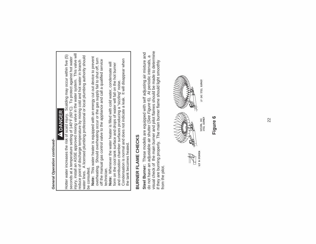
22
Gen
eral
Ope
ratio
n co
ntin
ued-
Hot
ter w
ater
incr
ease
s th
e ris
k of
sca
ld in
jury
. S
cald
ing
may
occ
ur w
ithin
five
(5)
seco
nds
at a
tem
pera
ture
set
ting
of 1
40F
(60
C).
To
prot
ect a
gain
st h
ot w
ater
in
jury
, ins
tall
an A
SS
E a
ppro
ved
mix
ing
valv
e in
the
wat
er s
yste
m.
This
val
ve w
ill
redu
ce p
oint
of d
isch
arge
tem
pera
ture
by
mix
ing
cold
and
hot
wat
er in
bra
nch
wat
er li
nes.
A li
cens
ed p
lum
bing
pro
fess
iona
l or l
ocal
plu
mbi
ng a
utho
rity
shou
ld
be c
onsu
lted.
N
ote:
Thi
s w
ater
hea
ter i
s eq
uipp
ed w
ith a
n en
ergy
cut
out
dev
ice
to p
reve
nt
over
heat
ing.
Sho
uld
over
heat
ing
occu
r or t
he g
as s
uppl
y fa
il to
shu
t off,
turn
of
f the
man
ual g
as c
ontro
l val
ve to
the
appl
ianc
e an
d ca
ll a
qual
ified
ser
vice
te
chni
cian
. N
ote:
Whe
neve
r the
wat
er h
eate
r is
fille
d w
ith c
old
wat
er, c
onde
nsat
e w
ill
form
on
the
cool
tank
sur
face
and
dro
ps o
f wat
er w
ill fa
ll on
the
hot b
urne
r an
d co
mbu
stio
n ch
ambe
r sur
face
s pr
oduc
ing
a “s
izzl
ing”
noi
se.
Con
dens
atio
n is
nor
mal
and
doe
s no
t ind
icat
e a
leak
. It
will
dis
appe
ar w
hen
the
tank
bec
omes
hea
ted.
B
UR
NER
FLA
ME
CH
ECK
S St
eel B
urne
r: T
hese
mod
els
are
equi
pped
with
sel
f adj
ustin
g ai
r mix
ture
and
do
not
hav
e an
adj
usta
ble
air s
hutte
r (S
ee F
igur
e 6)
. A
t per
iodi
c in
terv
als,
a
visu
al c
heck
of
the
mai
n bu
rner
and
pilo
t fla
mes
sho
uld
be m
ade
to d
eter
min
e
if th
ey a
re b
urni
ng p
rope
rly.
The
mai
n bu
rner
flam
e sh
ould
ligh
t sm
ooth
ly
from
the
pilo
t.
DA
NG
ER
Figu
re 6

23
MA
INTE
NA
NC
E
The
follo
win
g m
aint
enan
ce s
houl
d be
per
form
ed b
y a
qual
ified
ser
vice
te
chni
cian
at t
he m
inim
um p
erio
dic
inte
rval
s su
gges
ted
belo
w.
In s
ome
inst
alla
tions
, the
mai
nten
ance
inte
rval
may
be
mor
e fre
quen
t dep
endi
ng o
n th
e am
ount
of u
se a
nd th
e op
erat
ing
cond
ition
s of
the
wat
er h
eate
r. R
egul
ar
insp
ectio
n an
d m
aint
enan
ce o
f the
wat
er h
eate
r and
ven
t-air
inta
ke s
yste
m
will
hel
p to
insu
re s
afe
and
relia
ble
oper
atio
n.
1.
Ann
ually
che
ck th
e op
erat
ion
of th
e th
erm
osta
t.
2.
The
flow
of c
ombu
stio
n an
d ve
ntila
tion
air M
US
T N
OT
be re
stric
ted.
M
ake
sure
slo
ts in
jack
et a
re o
pen
and
unob
stru
cted
. C
lear
jack
et s
lot
open
ings
of a
ny d
irt, d
ust,
or o
ther
rest
rictio
ns. W
AR
NIN
G! T
he v
entil
atio
n ai
r sys
tem
may
be
HO
T.
3.
At a
ll tim
es k
eep
the
wat
er h
eate
r are
a cl
ear a
nd fr
ee fr
om c
ombu
stib
le
mat
eria
ls, g
asol
ine
and
othe
r fla
mm
able
vap
ors
and
liqui
ds.
4.
Bi-a
nnua
lly c
ondu
ct a
vis
ual c
heck
of t
he m
ain
and
pilo
t bur
ner f
lam
es to
de
term
ine
that
they
are
bur
ning
pro
perly
. S
ee B
urne
r Fla
me
Che
ck
sect
ion
of th
is in
stal
latio
n an
d op
erat
ion
man
ual.
If s
ootin
g or
oth
er
burn
er a
nom
alie
s ar
e ev
iden
t, sh
ut d
own
the
wat
er h
eate
r by
turn
ing
off
the
gas
per t
he in
stru
ctio
ns li
sted
in th
is m
anua
l or a
s lis
ted
on th
e w
ater
he
ater
.
5.
Ann
ually
rem
ove
the
inne
r doo
r and
mai
n bu
rner
ass
embl
y to
cle
an
orifi
ces
and
rela
ted
parts
of a
ny d
irt o
r oth
er fo
reig
n m
ater
ial.
Insp
ect t
he
burn
er p
orts
for o
bstru
ctio
ns o
r deb
ris a
nd c
lean
with
a w
ire b
rush
as
need
ed.
Wire
bru
sh a
nd/o
r vac
uum
cle
an th
e co
mbu
stio
n ch
ambe
r as
need
ed to
rem
ove
scal
e de
posi
ts a
nd d
ebris
. N
OTE
: It
is im
pera
tive
for
prop
er o
pera
tion
of th
e w
ater
hea
ter t
hat t
he in
ner d
oor b
e re
plac
ed in
the
orig
inal
loca
tion,
mak
ing
certa
in th
e re
seta
ble
ther
mal
sw
itch
is p
rope
rly
conn
ecte
d to
the
gas
cont
rol w
ire le
ads
prov
ided
.
IMPO
RTA
NT
The
wat
er h
eate
r sho
uld
be in
spec
ted
at a
min
imum
ann
ually
by
a qu
alifi
ed s
ervi
ce te
chni
cian
for d
amag
ed c
ompo
nent
s an
d/or
join
ts n
ot
seal
ed.
DO
NO
T op
erat
e th
is w
ater
hea
ter i
f any
par
t is
foun
d da
mag
ed
or if
any
join
t is
foun
d no
t sea
led.
W
AR
NIN
G
Wat
er h
eate
rs a
re h
eat p
rodu
cing
app
lianc
es.
To a
void
dam
age
or in
jury
th
ere
shal
l be
no m
ater
ials
sto
red
agai
nst t
he w
ater
hea
ter o
r ven
t-air
inta
ke
syst
em, a
nd p
rope
r car
e sh
all b
e ta
ken
to a
void
unn
eces
sary
con
tact
(e
spec
ially
by
child
ren)
with
the
wat
er h
eate
r and
ven
t-air
inta
ke s
yste
m.
UN
DER
NO
CIR
CU
MST
AN
CES
SH
ALL
FLA
MM
AB
LE M
ATE
RIA
LS, S
UC
H
AS
GA
SOLI
NE
OR
PA
INT
THIN
NER
BE
USE
D O
R S
TOR
ED IN
TH
E VI
CIN
ITY
OF
THIS
WA
TER
HEA
TER
, VEN
T-A
IR IN
TAK
E SY
STEM
OR
IN
AN
Y LO
CA
TIO
N F
RO
M W
HIC
H F
UM
ES C
OU
LD R
EAC
H T
HE
WA
TER
H
EATE
R O
R V
ENT-
AIR
INTA
KE
SYST
EM.

24
Mai
nten
ance
con
tinue
d-
6.
At l
east
onc
e a
year
, che
ck th
e co
mbi
natio
n te
mpe
ratu
re a
nd p
ress
ure
relie
f val
ve to
insu
re th
at th
e va
lve
has
not b
ecom
e en
crus
ted
with
lim
e.
Lift
the
leve
r at t
he to
p of
the
valv
e se
vera
l tim
es u
ntil
the
valv
e se
ats
prop
erly
with
out l
eaki
ng a
nd o
pera
tes
freel
y.
7.
Mon
thly
dra
in o
ff a
gallo
n of
wat
er to
rem
ove
silt
and
sedi
men
t.
8.
If
the
com
bina
tion
tem
pera
ture
and
pre
ssur
e re
lief v
alve
on
the
appl
ianc
e di
scha
rges
per
iodi
cally
, thi
s m
ay b
e du
e to
ther
mal
exp
ansi
on in
a c
lose
d w
ater
sup
ply
syst
em.
Con
tact
the
wat
er s
uppl
ier o
r loc
al p
lum
bing
in
spec
tor o
n ho
w to
cor
rect
this
situ
atio
n. D
o no
t plu
g th
e co
mbi
natio
n te
mpe
ratu
re a
nd p
ress
ure
relie
f val
ve o
utle
t.
9.
A c
ombi
natio
n sa
crifi
cial
ano
de ro
d/ho
t wat
er o
utle
t nip
ple
has
been
in
stal
led
to e
xten
d ta
nk li
fe.
The
anod
e ro
d sh
ould
be
insp
ecte
d pe
riodi
cally
(eve
ry 2
yea
rs) a
nd re
plac
ed w
hen
nece
ssar
y to
pro
long
tank
lif
e. W
ater
con
ditio
ns in
you
r are
a w
ill in
fluen
ce th
e tim
e in
terv
al fo
r in
spec
tion
and
repl
acem
ent o
f the
ano
de ro
d. C
onta
ct th
e pl
umbi
ng
prof
essi
onal
who
inst
alle
d th
e w
ater
hea
ter o
r the
man
ufac
ture
r lis
ted
on
the
ratin
g pl
ate
for a
node
repl
acem
ent i
nfor
mat
ion.
The
use
of a
wat
er
softe
ner m
ay in
crea
se th
e sp
eed
of a
node
con
sum
ptio
n. M
ore
frequ
ent
insp
ectio
n of
the
anod
e is
nee
ded
whe
n us
ing
softe
ned
(or p
hosp
hate
tre
ated
) wat
er.
10
. Th
e ve
nt s
yste
m m
ust b
e in
spec
ted
at le
ast o
nce
a ye
ar to
ens
ure
agai
nst
leak
age
of e
xhau
st p
rodu
cts.
W
AR
NIN
G
D
o no
t ope
rate
wat
er h
eate
r with
jum
pere
d, a
ltere
d, lo
osel
y tig
hten
ed o
r abs
ent c
ontr
ols
and/
or c
ompo
nent
s.
D
o no
t ope
rate
wat
er h
eate
r with
repl
acem
ent c
ontr
ols
and/
or
com
pone
nts,
whi
ch a
re n
ot e
xact
dup
licat
es o
r orig
inal
equ
ipm
ent.
Th
orou
ghly
insp
ect a
nd re
plac
e, (a
s ne
eded
) bur
ner i
nner
doo
r ga
sket
and
/or s
ight
win
dow
gas
ket a
ny ti
me
burn
er in
ner d
oor i
s re
mov
ed o
r dis
turb
ed.
R
epla
ce w
ater
hea
ter i
f inv
olve
d in
flam
mab
le v
apor
s in
cide
nt.
W
AR
NIN
G
Whe
n lif
ting
leve
r of t
he c
ombi
natio
n te
mpe
ratu
re a
nd p
ress
ure
relie
f va
lve,
hot
wat
er w
ill b
e re
leas
ed u
nder
pre
ssur
e. B
e ca
refu
l tha
t any
re
leas
ed w
ater
doe
s no
t res
ult i
n bo
dily
inju
ry o
r pro
pert
y da
mag
e.
WA
RN
ING
! TH
IS W
ATE
R M
AY
BE
HO
T.

25
Mai
nten
ance
con
tinue
d-
Con
tact
you
r sup
plie
r or p
lum
bing
pro
fess
iona
l for
repl
acem
ent p
arts
or
cont
act t
he c
ompa
ny a
t the
add
ress
giv
en o
n th
e ra
ting
plat
e of
the
wat
er
heat
er.
Pro
vide
the
part
nam
e, m
odel
and
ser
ial n
umbe
rs o
f the
wat
er h
eate
r whe
n or
derin
g pa
rts.
REA
D T
HE
WA
RR
AN
TY F
OR
A F
ULL
EXP
LAN
ATI
ON
OF
THE
LEN
GTH
O
F TI
ME
THA
T PA
RTS
AN
D T
HE
WA
TER
HEA
TER
AR
E W
AR
RA
NTE
D.
Com
plet
e th
e fo
llow
ing
info
rmat
ion
and
reta
in fo
r fut
ure
refe
renc
e:
Mod
el N
o:
S
eria
l No:
Ser
vice
Pho
ne
Day
s:__
____
____
____
____
Nig
hts:
Add
ress
:___
____
____
____
____
____
____
____
____
____
____
____
____
__
Sup
plie
r:
S
uppl
ier P
hone
No:
____
____
____
____
____
____
____
____
____
____
____
CA
UTI
ON
FO
R Y
OU
R S
AFE
TY, D
O N
OT
ATT
EM
PT
RE
PA
IR O
F C
OM
BIN
ATI
ON
G
AS
CO
NTR
OL,
BU
RN
ER
S O
R G
AS
PIP
ING
. R
EFE
R R
EP
AIR
S T
O A
Q
UA
LIFI
ED
SE
RV
ICE
TE
CH
NIC
IAN
.
Man
ufac
ture
d un
der o
ne o
r mor
e of
the
follo
win
g U
.S. P
aten
ts: R
E.3
4,53
4;
B1
5,34
1,77
0; 4
,416
,222
; 4,6
28,1
84; 4
,669
,448
; 4,6
72,9
19; 4
,808
,356
; 4,8
29,9
83;
4,86
1,96
8; 4
,904
,428
; 5,0
00,8
93; 5
,023
,031
; 5,0
52,3
46; 5
,081
,696
; 5,0
92,5
19;
5,11
5,76
7; 5
,199
,385
; 5,2
77,1
71; 5
,372
,185
; 5,4
85,8
79; 5
,574
,822
; 5,5
96,9
52;
5,66
0,16
5; 5
,682
,666
; 5,7
61,3
79; 5
,943
,984
; 5,9
54,4
92; 5
,988
,117
; 6,1
42,2
16;
6,39
5,28
0; 6
,684
,821
; 7,0
63,1
32; 7
,007
,748
O
ther
U.S
. and
For
eign
pat
ent a
pplic
atio
ns p
endi
ng.
Cur
rent
Can
adia
n P
aten
ts:
1,27
2,91
4; 1
,280
,043
; 1,2
89,8
32; 2
,045
,862
; 2,0
92,1
05; 2
,107
,012
; 2,1
08,1
86;
2,11
2,51
5

26
TRO
UB
LESH
OO
TIN
G C
HA
RT
LE
D S
tatu
s C
ontr
ol S
tatu
s Pr
obab
le C
ause
Non
e (L
ED
not
on
or
flash
ing)
M
illivo
lt po
wer
is n
ot
pres
ent.
Ligh
t pilo
t.
1.
Gas
val
ve is
func
tioni
ng
norm
ally
2.
G
as v
alve
is n
ot p
ower
ed.
Ligh
t pilo
t
One
flas
h an
d th
ree
seco
nd p
ause
.
If se
t poi
nt k
nob
is in
"P
ILO
T" p
ositi
on th
en p
ilot
flam
e is
det
ecte
d. (n
o fa
ults
).
Gas
val
ve is
pow
ered
and
wai
ting
for t
he s
et p
oint
kno
b to
be
turn
ed
to a
wat
er te
mpe
ratu
re s
ettin
g. If
th
e se
t poi
nt k
nob
is a
t des
ired
setti
ng th
e th
erm
osta
t is
satis
fied.
LE
D s
trobe
(tw
o qu
ick
flash
es) a
nd th
ree
seco
nd
paus
e
Ther
mos
tat c
allin
g fo
r hea
t (n
o fa
ults
) W
ater
hea
ter o
pera
ting
norm
ally
.
LED
on
cont
inuo
usly
. S
et p
oint
kno
b ha
s be
en
rece
ntly
turn
ed to
the
"OFF
" pos
ition
.
Set
poi
nt k
nob
was
rece
ntly
turn
ed
to "O
FF" p
ositi
on.
Wai
t unt
il LE
D
goes
out
bef
ore
atte
mpt
ing
to
relig
ht
Two
flash
es a
nd th
ree
seco
nd p
ause
.
Wea
k pi
lot f
lam
e de
tect
ed.
Sys
tem
will
rese
t whe
n pi
lot f
lam
e is
suf
ficie
nt.
1.
Uns
tabl
e pi
lot.
2.
P
ilot t
ube
bloc
ked
or
rest
ricte
d.
Thre
e fla
shes
and
thre
e se
cond
pau
se.
Insu
ffici
ent w
ater
hea
ting.
S
yste
m w
ill re
set.
1.
Tem
pera
ture
sen
sor o
ut o
f ca
libra
tion.
2.
P
ossi
ble
shor
t.
Four
flas
hes
and
thre
e se
cond
pau
se.
Exc
essi
ve ta
nk
tem
pera
ture
. Sys
tem
mus
t be
rese
t.
1.
Tem
pera
ture
sen
sor o
ut o
f ca
libra
tion.
2.
Fa
ulty
gas
val
ve.
Five
flas
hes
and
thre
e se
cond
pau
se.
Tem
pera
ture
Sen
sor f
ault.
1.
Dam
age
to th
e te
mpe
ratu
re
wire
. 2.
Te
mpe
ratu
re s
enso
r re
sist
ance
out
of r
ange
. 3.
R
epla
ce te
mpe
ratu
re s
enso
r.
4.
If te
mpe
ratu
re s
enso
r re
plac
emen
t doe
s no
t cor
rect
th
e pr
oble
m; V
erify
con
trol i
s no
t wet
or p
hysi
cally
dam
aged
5.
Tu
rn s
et p
oint
kno
b to
"OFF
" po
sitio
n. T
urn
set p
oint
kno
b to
"PIL
OT"
pos
ition
and
ligh
t pi
lot.
6.
Rep
lace
gas
val
ve if
five
flas
h er
ror p
ersi
sts.

27
TRO
UB
LESH
OO
TIN
G C
HA
RT
(CO
NTI
NU
ED)
LE
D S
tatu
s C
ontr
ol S
tatu
s Pr
obab
le C
ause
Six
flash
es a
nd th
ree
seco
nd p
ause
.
Wat
er le
ak d
etec
ted
by
acce
ssor
y m
odul
e (s
ome
mod
els)
.
Exc
essi
ve a
mou
nt o
f wat
er in
dra
in
pan/
wat
er d
am.
Seve
n fla
shes
and
thre
e se
cond
pau
se.
Gas
val
ve e
lect
roni
c fa
ult
dete
cted
.
1.
Ver
ify c
ontro
l is
not w
et o
r ph
ysic
ally
dam
aged
. 2.
Tu
rn s
et p
oint
kno
b to
"OFF
" po
sitio
n. T
urn
set p
oint
kno
b to
"PIL
OT"
pos
ition
and
ligh
t pi
lot.
3.
Rep
lace
gas
val
ve if
sev
en
flash
erro
r per
sist
s.
Eig
ht fl
ashe
s an
d th
ree
seco
nd p
ause
Fa
lse
pilo
t fla
me
pres
ent.
1.
Pilo
t val
ve s
tuck
in o
pen
posi
tion
2.
Tu
rn s
et p
oint
kno
b to
"OFF
" po
sitio
n. T
urn
set p
oint
kno
b to
"P
ILO
T" p
ositi
on a
nd li
ght p
ilot.
3.
Rep
lace
gas
val
ve if
eig
ht fl
ash
erro
r per
sist
s.

28
INST
ALL
ATI
ON
FO
R P
OTA
BLE
WA
TER
Fi
gure
7

29
PAR
TS L
IST
DR
AW
ING

30
PAR
TS L
IST
PA
RT
NA
ME
AN
D D
ESC
RIP
TIO
N
1. D
raft
Div
erte
r 14
. Dra
in V
alve
2. J
acke
t Hea
d P
an
15. P
iezo
Igni
ter
3. J
acke
t 16
. Gas
Val
ve
4. O
uter
Doo
r 17
. Ste
el B
urne
r
5. M
agne
sium
Ano
de–H
ot W
ater
Out
let
18. O
rific
e
6. F
lue
Baf
fle A
ssem
bly
19. G
as F
eedl
ine
to B
urne
r
7. D
ip T
ube–
Col
d W
ater
Inle
t 20
. Gas
Fee
dlin
e to
Pilo
t
8. T
empe
ratu
re a
nd P
ress
ure
Rel
ief V
alve
21
. The
rmoc
oupl
e Le
ad
9. G
lass
Lin
ed T
ank
22. P
iezo
Igni
ter L
ead
10. C
ombu
stio
n C
ham
ber A
ssem
bly
23. P
ilot A
ssem
bly
11. J
acke
t Bas
e P
an
12. I
nner
Doo
r Gas
ket
13. I
nner
Doo
r Ass
embl
y
13A
. Hig
h te
mpe
ratu
re li
mit
switc
h

31
THE
FOLL
OW
ING
INST
RU
CTI
ON
S A
RE
FOR
INST
ALL
ATI
ON
OF:
G
AS
WA
TER
HEA
TER
S SU
ITA
BLE
FO
R W
ATE
R (P
OTA
BLE
) HEA
TIN
G A
ND
SPA
CE
HEA
TIN
G
1.
All
pipi
ng c
ompo
nent
s co
nnec
ted
to th
is w
ater
hea
ter f
or s
pace
hea
ting
appl
icat
ions
mus
t be
suita
ble
for u
se w
ith p
otab
le w
ater
. In
M
assa
chus
etts
, spa
ce h
eatin
g pi
ping
leng
th m
ust n
ot e
xcee
d 50
feet
. 2.
To
xic
chem
ical
s, s
uch
as th
ose
used
for b
oile
r tre
atm
ent,
mus
t not
be
intro
duce
d in
to p
otab
le w
ater
use
d fo
r spa
ce h
eatin
g.
3.
This
wat
er h
eate
r mus
t not
be
conn
ecte
d to
an
exis
ting
heat
ing
syst
em
or c
ompo
nent
(s) p
revi
ousl
y us
ed w
ith a
non
-pot
able
wat
er h
eatin
g ap
plia
nce.
4.
W
hen
the
syst
em re
quire
s w
ater
for s
pace
hea
ting
at te
mpe
ratu
res
high
er
than
requ
ired
for o
ther
mea
ns, s
uch
as a
n A
SS
E a
ppro
ved
mix
ing
valv
e m
ust b
e in
stal
led
to te
mpe
r the
wat
er fo
r tho
se u
ses
in o
rder
to re
duce
the
scal
d ha
zard
pot
entia
l. P
leas
e re
fer t
o fig
ure
8 an
d fig
ure
9 fo
r sug
gest
ed p
ipin
g ar
rang
emen
ts.
Figu
re 8
Fi
gure
9

32
NO
TES