Embed Size (px)
Citation preview

Installation & Operating Manual
Form GTI+ IOM 11-14

GTI+ IOM 11-14All rights reserved ©ALTRONIC, LLC 2014 2
1.0 SAFETY PRECAUTIONS 1.1 Follow all local codes when installing the Bi-Fuel® System. All gas train
components should be installed and/or inspected by a licensed plumbing contractor.
Ensure adequate ventilation in work area in order to prevent accumulation of gas caused by undetected leaks. Accumulations of natural gas or other hydrocarbon vapors can result in high-energy explosions that can damage or destroy structures and cause injury or death to nearby personnel.
An appropriately rated fire extinguisher must be kept in a readily accessible location during all phases of installation.
Observe all warnings found on the equipment. Ensure that warning labels are easily legible and not obstructed by dirt, grease or other equipment.
Do not install any component that appears to have been tampered with, subjected to high temperatures or damaged in any way. Installation of a damaged component may result in gas leaks and/or improper operation of the Bi-Fuel System.
Do not attempt to operate engine until a thorough leak check has been completed. Use of an industry standard leak detection fluid (such as “Snoop”) is required on all gas connections, joints and flanges. ALL LEAKS MUST BE FIXED PRIOR TO OPERATING ENGINE IN BI-FUEL MODE.
All Bi-Fuel System components must be used within the temperature and pressure ranges specified in this manual or as otherwise dictated by component labeling. Operation of components outside of design temperature and pressure limits can result in fire, explosion and/ or harm to personnel.
2.0 DESCRIPTION AND THEORY OF OPERATION 2.1 General The GTI Bi-Fuel System is a retrofit technology that allows diesel engines to
operate on a mixture of diesel fuel and natural gas. This is achieved through the use of proprietary and patented technologies that are installed externally of the engine. Conversion to GTI Bi-Fuel requires no major changes or modifications of the engine and allows the engine to safely operate on gas percentages up to a maximum of 70% of the total fuel requirement. After conversion to bi-fuel, the engine can still be operated on 100% diesel fuel without loss of power or efficiency. The Bi-Fuel System has been designed to allow for switching of fuel modes during full or part load conditions, without interruption in engine speed, power or stability. The Bi-Fuel System utilizes a fumigation gas delivery method whereby gas is delivered to the cylinders via the standard engine air-intake system and is then ignited by a diesel “pilot” which acts as an ignition source for the air-gas mixture.
2.2 Applications The Bi-Fuel System has been designed for constant speed applications such
as engine-driven electric power generators, engine-driven pumps, compressors and other industrial and commercial applications. Variable speed applications may also be converted to bi-fuel depending on the governing system used and the method of engine operation. GTI+ is designed to accommodate adjustments in the optimal substitution rate as a result of changes in conditions that would normally require a limitation to the maximum possible substitution over a given load window: or a limitation to the maximum possible load window with a given rate of substitution.
NOTE: It is important to perform leaks tests on all intake manifold and aftercooler components, joints and covers.
NOTE: Engine must be equipped with a Full authority governor to operate properly with the GTI Bi-Fuel system.
WARNING: deviation from installation instructions and technical guidelines may lead to improper operation of the bi-fuel system, damage or destruction of the converted diesel engine and associated machinery, and/or personal injury or death to operators and nearby personnel.
CAUTION: This manual is intended for use by qualified and experienced technical personnel with formal train-ing in the operation and maintenance of heavy-duty diesel engines. This manual was neither designed nor in-tended as a technical guide to diesel engines and assumes a high degree of understanding of diesel engine operation and theory by the reader. ONLY QUALIFIED PERSONNEL SHOULD ATTEMPT INSTALLATION OF THE GTI BI-FUEL SYSTEM.
NOTE: It is highly recommended that gas detection be installed to protect an enclosed environment against any possible gas leaks.
NOTE: Substitution rates can vary from 25% to 70%, subject to gas quality and other application conditions.

GTI+ IOM 11-14All rights reserved ©ALTRONIC, LLC 2014 3
GTI+ Bi-Fuel® System Diagram
2.3 Compatible Fuel Types The Bi-Fuel System is compatible with a wide range of gas compositions and
BTU levels. It is recommended that the gas be treated for any corrosives prior to use. For applications of pure propane, special considerations and precautions are necessary. Any questions concerning specific gas quality, please contact your Master Distributor. Ideally, pipeline supplied gas will have a high concentration of methane and a low overall concentration of heavier hydrocarbon gases (see table). For lower quality gases (pipeline supplied or other), reductions in gas substitution rate may be required.
Methane Ethane Propane Butane Nitrogen Carbon Oxygen
97.09 0.88 0.26 0.09 1.41 0.12 —
High Quality Pipeline Gas/Composition in Volume %
2.4 Gas Delivery System The Bi-Fuel System utilizes a vacuum-based gas control system, whereby
changes in combustion airflow result in a corresponding change of gas flow to the engine. The gas is supplied to the engine with the use of an air-gas mixing device (mixer) installed upstream of the turbocharger compressor inlet.
2.4.1 Air-Gas Mixer The Air-Gas Mixer (AGM) blends engine intake-air with an appropriate quantity
of natural gas as required for combustion. The AGM is installed upstream of the turbocharger compressor inlet and downstream of the engine air cleaner housing. The GTI Air-Gas Mixer is a variable venturi design and does not utilize a moveable air-throttle.
Air entering the AGM is diverted around a gas diffuser section, causing a turbulent, low pressure area to form. This low pressure area draws natural gas from the diffuser section gas reservoir through a radial pattern of precision machined gas outlet orifices. Gas is introduced into the turbulent airflow area immediately downstream of the gas diffuser section, allowing for a high degree of mixing action of the two media with a minimum of airflow restriction.
NOTE: These instructions apply only to diesel engines equipped with turbochargers. For all non-turbo installations, consult the factory prior to installation.
GTI+ IOM 11-14All rights reserved ©ALTRONIC, LLC 2014 4
The CAD-designed AGM is constructed of aerospace quality materials that have been CNC-machined and then assembled using a state-of-art welding process. The AGM is mil-spec anodized for surface hardness and corrosion protection. The GTI Air-Gas Mixer comes standard in 3", 4", 5", 6", 7" and 8" O.D. (76, 102, 127, 152, 178 and 203mm O.D.). Contact factory for other sizes.
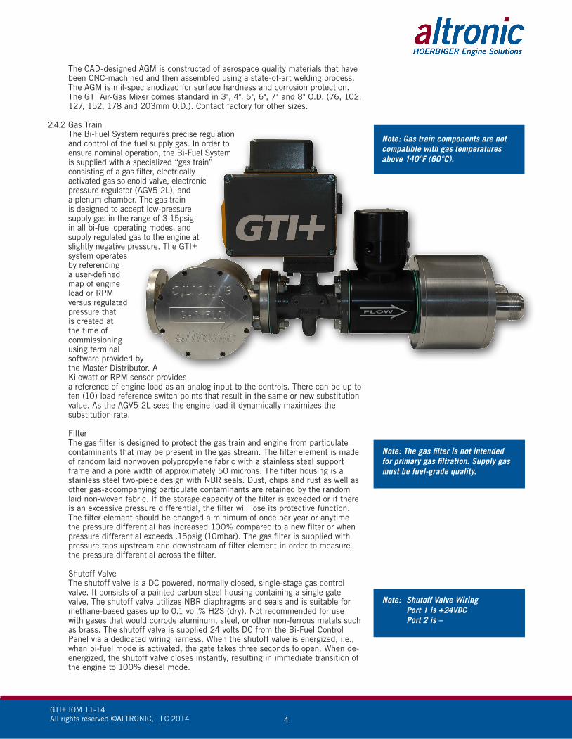
2.4.2 Gas Train The Bi-Fuel System requires precise regulation
and control of the fuel supply gas. In order to ensure nominal operation, the Bi-Fuel System is supplied with a specialized “gas train” consisting of a gas filter, electrically activated gas solenoid valve, electronic pressure regulator (AGV5-2L), and a plenum chamber. The gas train is designed to accept low-pressure supply gas in the range of 3-15psig in all bi-fuel operating modes, and supply regulated gas to the engine at slightly negative pressure. The GTI+ system operates by referencing a user-defined map of engine load or RPM versus regulated pressure that is created at the time of commissioning using terminal software provided by the Master Distributor. A Kilowatt or RPM sensor provides a reference of engine load as an analog input to the controls. There can be up to ten (10) load reference switch points that result in the same or new substitution value. As the AGV5-2L sees the engine load it dynamically maximizes the substitution rate.
Filter The gas filter is designed to protect the gas train and engine from particulate
contaminants that may be present in the gas stream. The filter element is made of random laid nonwoven polypropylene fabric with a stainless steel support frame and a pore width of approximately 50 microns. The filter housing is a stainless steel two-piece design with NBR seals. Dust, chips and rust as well as other gas-accompanying particulate contaminants are retained by the random laid non-woven fabric. If the storage capacity of the filter is exceeded or if there is an excessive pressure differential, the filter will lose its protective function. The filter element should be changed a minimum of once per year or anytime the pressure differential has increased 100% compared to a new filter or when pressure differential exceeds .15psig (10mbar). The gas filter is supplied with pressure taps upstream and downstream of filter element in order to measure the pressure differential across the filter.
Shutoff Valve The shutoff valve is a DC powered, normally closed, single-stage gas control
valve. It consists of a painted carbon steel housing containing a single gate valve. The shutoff valve utilizes NBR diaphragms and seals and is suitable for methane-based gases up to 0.1 vol.% H2S (dry). Not recommended for use with gases that would corrode aluminum, steel, or other non-ferrous metals such as brass. The shutoff valve is supplied 24 volts DC from the Bi-Fuel Control Panel via a dedicated wiring harness. When the shutoff valve is energized, i.e., when bi-fuel mode is activated, the gate takes three seconds to open. When de-energized, the shutoff valve closes instantly, resulting in immediate transition of the engine to 100% diesel mode.
Note: Gas train components are not compatible with gas temperatures above 140°F (60°C).
Note: The gas filter is not intended for primary gas filtration. Supply gas must be fuel-grade quality.
Note: Shutoff Valve Wiring Port 1 is +24VDC Port 2 is –
GTI+ IOM 11-14All rights reserved ©ALTRONIC, LLC 2014 5
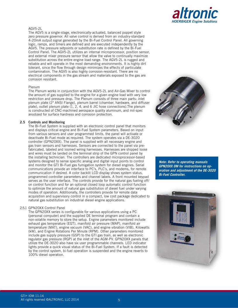
AGV5-2L The AGV5 is a single-stage, electronically-actuated, balanced poppet style
zero pressure governor. All valve control is derived from an industry-standard 4-20mA output signal generated by the Bi-Fuel Control Panel. All governing logic, ramps, and timers are defined and are executed independently by the AGV5. The pressure setpoints or substitution rate is defined by the Bi-Fuel Control Panel. The AGV5-2L utilizes an internal microprocessor, position sensor, and external mixer pressure sensor that allow the valve to continually maximize substitution across the entire engine load range. The AGV5-2L is rugged and reliable and will operate in the most demanding environments. It is highly dirt tolerant, since the flow through design minimizes the effects of particulate contamination. The AGV5 is also highly corrosion-resistant. There are no electrical components in the gas stream and materials exposed to the gas are corrosion resistant.
Plenum The Plenum works in conjunction with the AGV5-2L and Air-Gas Mixer to control
the amount of gas supplied to the engine for a given engine load with very low restriction and pressure drop. The Plenum consists of three main parts: inlet plenum plate (2" ANSI Flange), plenum barrel (chamber, hardware, and diffuser plate), outlet plenum plate (1, 2, 4, and 6 JIC hose connections).The plenum is constructed of CNC-machined aerospace quality aluminum, and mil-spec anodized for surface hardness and corrosion protection.
2.5 Controls and Monitoring The Bi-Fuel System is supplied with an electronic control panel that monitors
and displays critical engine and Bi-Fuel System parameters. Based on input from various sensors and user programmed limits, the panel will activate or deactivate Bi-Fuel mode as required. The system operates via a DE-3020 controller (GPN20XX). The panel is supplied with all necessary engine and gas train sensors and harnesses. Sensors are connected to the panel via pre-fabricated, labeled and loomed wiring harnesses. Harnesses are shipped loose and wires must be landed on the terminal strip of the GPN control panel by the installing technician. The controllers are dedicated microprocessor-based systems designed to sense specific analog and digital input points to control and monitor the GTI Bi-Fuel gas fumigation system for diesel engines. Serial communications provide an interface to PC’s, PLC’s, and modems, for remote communication if desired. A color backlit LCD display shows system status, programmed controller parameters and channel labels. A front mounted keypad serves as the user interface. The controls provide for the natural gas fueling off/on control function and for an optional closed loop automatic control function to optimize the amount of natural gas substitution of diesel fuel under varying modes of operation. Additionally, the controllers provide for remote data acquisition and supervisory control in a compact, low cost package dedicated to natural gas substitution on industrial diesel engine applications.
2.5.1 GPN20XX Control Panel The GPN20XX series is configurable for various applications using a PC
(personal computer) and the supplied DE terminal program and contain a non-volatile memory to store the setup. Engine parameters monitored include exhaust gas temperature (EGT), manifold air pressure (MAP), manifold air temperature (MAT), engine vacuum (VAC), and engine vibration (VIB), Kilowatts (kW), and Engine Rotations Per Minute (RPM). Other parameters monitored include gas supply pressure (GSP) to the GTI gas train, as well as electronic regulator gas pressure (RGP) at the inlet of the AGM-PV. GPN20XX panels that utilize the DE-3020 also have six user programmable channels. LED indicator lights provide a quick visual status of the Bi-Fuel System. If a fault is detected by the control system, bi-fuel operation is suspended and the engine reverts to 100% diesel operation.
Note: Refer to operating manuals GPN20XX OM for instructions on op-eration and adjustment of the DE-3020 Bi-Fuel Controller.

GTI+ IOM 11-14All rights reserved ©ALTRONIC, LLC 2014 6
Control Logic Programmed setpoints are defined as either CONTROL or SAFETY SHUTDOWN.
Manifold air pressure (MAP), Kilowatts (kW), and RPM are usually the only CONTROL setpoints used to determine the engine load “window” in which Bi-Fuel operation will be allowed. The control panel uses the engine MAP, kW, or RPM data to determine engine load and the user is able to program minimum and maximum MAP, kW, or RPM values, where the minimum value sets the “light-load limit” for bi-fuel operation and the maximum value sets the “high-load limit” for bi-fuel operation.
All other monitored parameters are defined as SAFETY SHUTDOWN; in the
event a programmed limit is exceeded, the control panel will deactivate bi-fuel mode and return the engine to 100% diesel fuel operation.
All DE-20XX control panel models feature a “Bi-Fuel Inhibit” feature which prevents operation in bi-fuel mode until an external contact is closed. The external contact is typically a relay indicating an “engine run” or “breaker closed” condition.
All DE-20XX control panels feature a “safety” feature which prevents operation in bi-fuel mode until an external contact is closed and the user resets the panel. The external contact is typically Gas Detection Device.
Parameters monitored by GPN20XX Control Panel:
Exhaust Gas Temperature (EGT) The control panel monitors EGT to protect against excessive combustion
temperatures while operating in bi-fuel mode. The user programs a MAXIMUM allowable value for EGT. The panel comes standard with 1 or 2 channels of EGT monitoring. EGT is typically monitored for each parallel turbo. EGT is displayed in either Celsius or Fahrenheit units and is monitored using a “K” type thermocouple. In the event EGT exceeds the programmed safety limit, the control panel automatically switches the engine fuel mode to 100% diesel operation.
Manifold Air Temperature (MAT) MAT is monitored by the control panel to protect against excessive temperature
increases that could lead to a knocking condition in bi-fuel mode. The user programs a MAXIMUM allowable value for MAT. The panel comes standard with 1 to 4 channels of MAT monitoring for each discrete manifold or aftercooler. MAT is displayed in either Celsius or Fahrenheit units and is monitored using a “K” type thermocouple. In the event MAT exceeds the programmed limit value, the control panel automatically switches the engine fuel mode to 100% diesel operation.
Manifold Air Pressure (MAP) MAP is monitored by the control panel to determine engine load. The user
programs MINIMUM and MAXIMUM values for MAP. The minimum value sets the minimum engine load limit for bi-fuel operation and the maximum value sets the maximum load limit for bi-fuel operation. Once these values are programmed, the engine will only operate in bi-fuel mode when the load is ABOVE the programmed MINIMUM value and BELOW the programmed MAXIMUM value. The control panel comes standard with 1 to 4 channels of MAP monitoring for each discrete intake-air manifold. MAP is displayed in either psig or kPa units and is monitored using a pressure transducer.
Engine Vacuum (VAC) VAC is monitored by the control panel to protect against excessive engine air-filter
restriction. Excessive air-filter restriction and associated high VAC levels can result in an over fueling condition in bi-fuel mode. The panel comes standard with 1 to 4 channels of VAC monitoring for each discrete engine air-intake manifold. In the event VAC exceeds the programmed limit value, the control panel automatically switches the engine fuel mode to 100% diesel operation. The user programs a MINIMUM value for engine VAC. VAC is displayed in either psig or kPa units and is monitored using a pressure transducer.
Engine Vibration (VIB) VIB is monitored by the control panel to protect against excessive engine
vibration. Excessive engine vibration during bi-fuel operation may indicate a knocking condition or other combustion related abnormality. The system
Note: Violation of a SAFETY SHUTDOWN setpoint will not result in shutdown of the engine, only a change in fuel mode. The control panel changes engine fuel mode by energizing or de-energizing the shutoff valve. In the event of a safety shutdown, the DE controller will display the cause of the shutdown and activate a red LED indicator on the GPN control panel face.
GTI+ IOM 11-14All rights reserved ©ALTRONIC, LLC 2014 7
comes standard with 1 or 2 channels of VIB. VIB is typically monitored for each bank of cylinders (one VIB channel for in-line engines, two VIB channels for V engines). The user programs a MAXIMUM allowable value for VIB. In the event VIB exceeds the programmed limit value, the control panel automatically switches the engine fuel mode to 100% diesel operation. VIB is displayed in either inches per second (IPS) or millimeters per second (MPS) units and is monitored using a vibration transducer.
Gas Supply Pressure (GSP) GSP is monitored by the control panel in order to protect against variations in gas
supply pressure. The user programs MINIMUM and MAXIMUM values for GSP. The GPN20XX series Bi-Fuel System control panels come standard with one channel of GSP monitoring. GSP is monitored at the inlet to the GTI-supplied gas train. In the event GSP exceeds the programmed limit values, the control panel automatically switches the engine fuel mode to 100% diesel operation. GSP is displayed in either psig or kPa values and is monitored using a pressure transducer.
kW kW is monitored by the control panel to determine engine load. The user
programs MINIMUM and MAXIMUM values for kW. The minimum value sets the minimum engine load limit for bi-fuel operation and the maximum value sets the maximum load limit for bi-fuel operation. Once these values are programmed, the engine will only operate in bi-fuel mode when the load is ABOVE the programmed minimum value and BELOW the programmed maximum value. The control panel comes standard with 1 channel of kW monitoring.
RPM RPM is monitored by the control panel to determine engine speed/load. The user
programs MINIMUM and MAXIMUM values for RPM. The minimum value sets the minimum engine speed/load limit for bi-fuel operation. Once these values are programmed, the engine will only operate in bi-fuel mode when the RPM is ABOVE the programmed minimum value and BELOW the programmed maximum value. The control panel comes standard with 1 channel of RPM monitoring.
AGV5 I/P (CH28) AGV5 or Regulated Gas Pressure (RGP) is monitored by the control panel to
determine gas pressure at the AGM-PV. The user programs MINIMUM and MAXIMUM values for AGV5 to prevent over-pressure conditions. The panel comes standard with 1 channel of AGV5 monitoring. In the event RGP exceeds the programmed limit value, the control panel automatically switches the engine fuel mode to 100% diesel operation.
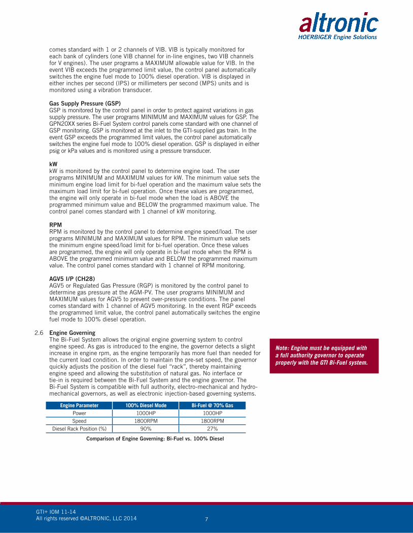
2.6 Engine Governing The Bi-Fuel System allows the original engine governing system to control
engine speed. As gas is introduced to the engine, the governor detects a slight increase in engine rpm, as the engine temporarily has more fuel than needed for the current load condition. In order to maintain the pre-set speed, the governor quickly adjusts the position of the diesel fuel “rack”, thereby maintaining engine speed and allowing the substitution of natural gas. No interface or tie-in is required between the Bi-Fuel System and the engine governor. The Bi-Fuel System is compatible with full authority, electro-mechanical and hydro-mechanical governors, as well as electronic injection-based governing systems.
Engine Parameter 100% Diesel Mode Bi-Fuel @ 70% Gas Power 1000HP 1000HP Speed 1800RPM 1800RPM
Diesel Rack Position (%) 90% 27%
Comparison of Engine Governing: Bi-Fuel vs. 100% Diesel
Note: Engine must be equipped with a full authority governor to operate properly with the GTI Bi-Fuel system.
GTI+ IOM 11-14All rights reserved ©ALTRONIC, LLC 2014 8
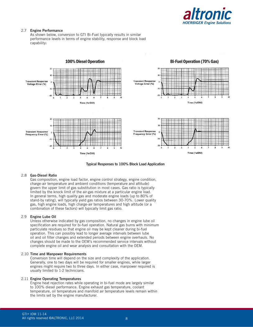
2.7 Engine Performance As shown below, conversion to GTI Bi-Fuel typically results in similar
performance levels in terms of engine stability, response and block load capability:
2.8 Gas-Diesel Ratio Gas composition, engine load factor, engine control strategy, engine condition,
charge-air temperature and ambient conditions (temperature and altitude) govern the upper limit of gas substitution in most cases. Gas ratio is typically limited by the knock limit of the air-gas mixture at a particular engine load. In general terms, high quality gas and moderate engine loads (up to 80% of stand-by rating), will typically yield gas ratios between 30-70%. Lower quality gas, high engine loads, high charge-air temperatures and high altitude (or a combination of these factors) will typically limit gas ratio.
2.9 Engine Lube Oil Unless otherwise indicated by gas composition, no changes in engine lube oil
specification are required for bi-fuel operation. Natural gas burns with minimum particulate residues so that engine oil may be kept cleaner during bi-fuel operation. This can possibly lead to longer average intervals between lube oil and oil filter changes and extended periods between engine overhauls. No changes should be made to the OEM’s recommended service intervals without complete engine oil and wear analysis and consultation with the OEM.
2.10 Time and Manpower Requirements Conversion time will depend on the size and complexity of the application.
Generally, one to two days will be required for smaller engines, while larger engines might require two to three days. In either case, manpower required is usually limited to 1-2 technicians.
2.11 Engine Operating Temperatures Engine heat rejection rates while operating in bi-fuel mode are largely similar
to 100% diesel performance. Engine exhaust gas temperature, coolant temperature, oil temperature and manifold air temperature levels remain within the limits set by the engine manufacturer.
Bi-Fuel Operation (70% Gas)100% Diesel Operation
Typical Responses to 100% Block Load Application
GTI+ IOM 11-14All rights reserved ©ALTRONIC, LLC 2014 9
2.12 Engine Efficiency Because the Bi-Fuel System utilizes a low restriction air-gas mixing device
and maintains the excess-air operation of the diesel engine, net fuel efficiency (specific fuel consumption) is normally equivalent to 100% diesel operation. For each unit of diesel fuel displaced during bi-fuel operation, a calorically equivalent unit of natural gas will be needed to maintain engine power.
2.13 Bi-Fuel Emissions Bi-fuel operation will typically reduce production of nitrogen oxides, sulfur
oxides, reactive hydrocarbons, carbon dioxide and particulates. Exhaust opacity levels (visual emissions) are also typically reduced. Altronic makes no guarantee of emissions levels in bi-fuel operation. Altronic is not responsible for any impact on engine tier rating certification in bi-fuel operation.
2.14 Engine Warranty Installation of the Bi-Fuel System does not generally impact factory engine
warranties. Because the engine is not modified from the original design, OEM’s typically take the position that while they will not be responsible for bi-fuel related failures, the full force and effect of their warranty will remain valid after conversion to bi-fuel.
2.15 Bi-Fuel System Warranty All components of the Bi-Fuel System including mixers, electronic controllers
and gas train components are covered by a limited warranty offered by Altronic. Please reference Altronic GTI Bi-Fuel® Warranty statement for complete details.
3.0 GAS SUPPLY
3.1 General The term “natural gas” generally refers to a combustible, gaseous mixture
of simple hydrocarbon (HC) compounds, usually found in deep underground reservoirs. Natural gas is primarily composed of methane (CH4/C1), but can also contain small amounts of other gases, including ethane, propane, butane and other compounds. At room temperature and pressure, methane is a colorless and odorless gas. Gas distributors/processors typically add odorant to the natural gas in order to alert operators to gas leaks. Natural gas is typically distributed via pipelines, but may also be transferred/stored in the form of LNG (liquid natural gas) or CNG (compressed natural gas).
3.2 Gas Variation Pipeline gas typically has little variation in quality and composition on a day
to day basis and is normally made up of >90% methane. Gas composition is an important factor for bi-fuel operation as the combustion characteristics of methane differ substantially from heavier hydrocarbon compounds. Generally, as the methane content of the fuel decreases and the heavy-HC content increases, the combustion characteristics of the fuel will change and may require a lower substitution percentage of natural gas. While the heating value of pipeline quality natural gas will vary somewhat, it is generally in the range of 1000Btu/scf or 37.25MJ/m3. A comparison of summer and winter gas composition should be made to determine any seasonal variation in gas composition.
3.3 Non-Pipeline Gases Other methane-based gases can be utilized with the Bi-Fuel System such as
wellhead gas and bio-gas. When utilizing gases other than pipeline quality, the following factors must be considered:
Methane content Heavy hydrocarbon content Heating value Inert gas content Moisture content Caustics Particulates
For reasons explained above, it is important to determine the base composition
Note: If the fuel has a heavy hydrocarbon concentration of >20% in the normal gas stream, or alternately, can have periodic “slugs” of heavy-hydrocarbons exceeding >20%, it may be necessary to decrease the gas substitution percentage and/or de-rate the engine during bi-fuel operation.
GTI+ IOM 11-14All rights reserved ©ALTRONIC, LLC 2014 10
of the fuel gas as well as the possible range of composition prior to installation of the Bi-Fuel System. Wellhead gas often consists of a greater fraction of heavy HC’s, and in some cases, may have less than 50% methane. The installer should be wary of so called “hot gas” which, due to high HC concentrations, can have heat rates in excess of 1200Btu/scf (44MJ/m3).
3.4 Filtration For non-pipeline gases (and some lower quality pipeline gases), it is important
to determine if sufficient filtering means have been incorporated in the gas supply line such that particulate and liquid contents in the fuel are kept to a level approximating fuel grade standards. GTI recommends, at a minimum, the use of a high quality, coalescing type filter for all non-pipeline applications. It is also important to determine what caustic compounds, if any, are present in the fuel which may potentially cause harm to the engine and/or gas components of the Bi-Fuel System. Additional filtration or treatment may be required in order to protect against engine damage. For bio-gas fuels derived from landfills, waste treatment facilities, etc., it is not uncommon to see high levels of caustic compounds such as sulphur, which when combined with small amounts of water can form damaging acids. It is possible to filter-out these types of contaminants, and filtration should be utilized if caustic compounds are present in the fuel.
3.5 Flow and Pressure For purposes of sizing gas supply piping and/or specifying gas regulators and
meters, the following general guidelines are recommended:
Flow: For estimating gas flow requirements for electrical power generation applications, assume a maximum flow requirement of 8 standard cubic feet per hour per kWe (scfh/kWe) or 0.23 cubic meter per kWe (m3/kWe). For example, a 1500kWe generator will require maximum gas flow of 12,000 (1500 x 8) scfh or 345 m3/hr. (0.23 x 1500).
For pump or compressor applications (or other direct drive systems), assume a gas flow rate of 6.4scfh/h.p. or 0.18m3/h.p. For example, a compressor drive engine operating at 600h.p. will require a gas flow of 3,840scfh (600 x 6.4) or 108m3/hr.
The guidelines outlined above assume gas flow based on the highest allowable gas substitution ratio. Actual gas flows may be significantly less than calculated depending on maximum possible gas ratio for a given application.
Gas flow estimates are based on pipeline grade natural gas with typical heating values. For estimating gas flow requirements for non-pipeline gases, please contact GTI.
Pressure: The GTI+ gas train has been designed to work with a regulated, low pressure gas supply of between 3 and 15psig (20.68-103.4kPa). For optimum performance, GTI recommends a working pressure of 3-15psig (20.68-103.4kPa), with a maximum deviation of <0.3psig (<2.068kPa) from the set pressure in all operating modes.
Note: It is the responsibility of the end-user to ensure that the gas supplied to the engine is “fuel grade quality” and sufficiently treated to prevent engine damage.
Note: It is critical that the gas supply system be designed and installed to provide the required steady state pressure at the full gas load of the facility (including all GTI-equipped gensets operating at full load) free of pressure fluctuations and oscillations at the gas train inlet. GTI accepts no responsibility for design of the gas supply system upstream of the inlet to the gas train filter.
Note: to convert from KVA to kWe, multiply KVA value by 0.8.
Note: Rapid deviation or oscillation of supply gas pressure in Bi-Fuel mode indicates a malfunctioning or improperly specified primary regulator. Rapid changes in gas supply pressure can result in engine instability during Bi-Fuel operation.
GTI+ IOM 11-14All rights reserved ©ALTRONIC, LLC 2014 11
Failure to follow these instructions may result in fire, explosion, or improper engine operation causing property damage, injury, or loss of life. Personnel who lack appropriate training should NOT attempt to install the air-gas mixer.
WARNING:
Installation of the Air-Gas Mixer may require removal of the turbo-compressor air supply conduit. Operation of the engine with an exposed turbo-compressor inlet represents an extreme hazard to nearby personnel. Engine should be in “manual stop” mode while compressor inlet is exposed.
WARNING:
No modifications may be made to the Air-Gas Mixer. Unauthorized modifications to the Air-Gas Mixer may result in improper operation of the engine and/or damage to the converted engine.
CAUTION:
Before installation of the mixer, an operational check of the air intake manifold system of the engine, including charge-air cooling system, should be completed to verify that no leaks exist.
CAUTION:
4.0 INSTALLATION
4.1 Mount the control panel(s) to a post or to a suitable flat surface so that the display is at a convenient viewing height.
4.2 Air-Gas Mixer Installation The Air-Gas Mixer (AGM) is installed in the engine air intake system between
the air filter housing and turbocharger compressor inlet. The AGM is typically installed using either the existing “hump hose” connectors in the intake conduit, or with hump hose connectors or adaptors supplied with the Bi-Fuel System (or locally sourced).
The AGM is unidirectional and will not function if installed incorrectly. Install the AGM with the arrow facing the turbocharger compressor inlet.
For engines with two or more air intake systems, it will be necessary to install one (1) AGM for each primary turbo. If properly specified, the Bi-Fuel System should be supplied with the appropriate quantity of Air-Gas Mixers for the engine to be converted. If unsure of number of Air-Gas Mixers required for a particular application, please contact your supplier for technical support.
The AGM may be installed at any angle as required by the geometry of the original air intake system.
Before installation of the AGM, determine the approximate location where the gas train will be installed in order to determine size and any possible routing conflicts of the flexible gas delivery line. Relocation of the air filter housing(s) may be required in order to provide space for the AGM. Before disassembly of the intake conduit, appropriate measurements should be taken to determine final location of AGM and/or air filter housing.
Note: Any leaks in the intake mani-fold system may result in the release of a flammable air-gas mixture.
Note: The AGM is marked to indicate direction of air flow.
Note: Installation of the AGM should not significantly alter the routing or geometry of the original engine air intake system. Ensure AGM will not make contact with any metal surfaces, as engine vibration will cause chafing and eventual failure of the AGM.
GTI+ IOM 11-14All rights reserved ©ALTRONIC, LLC 2014 12
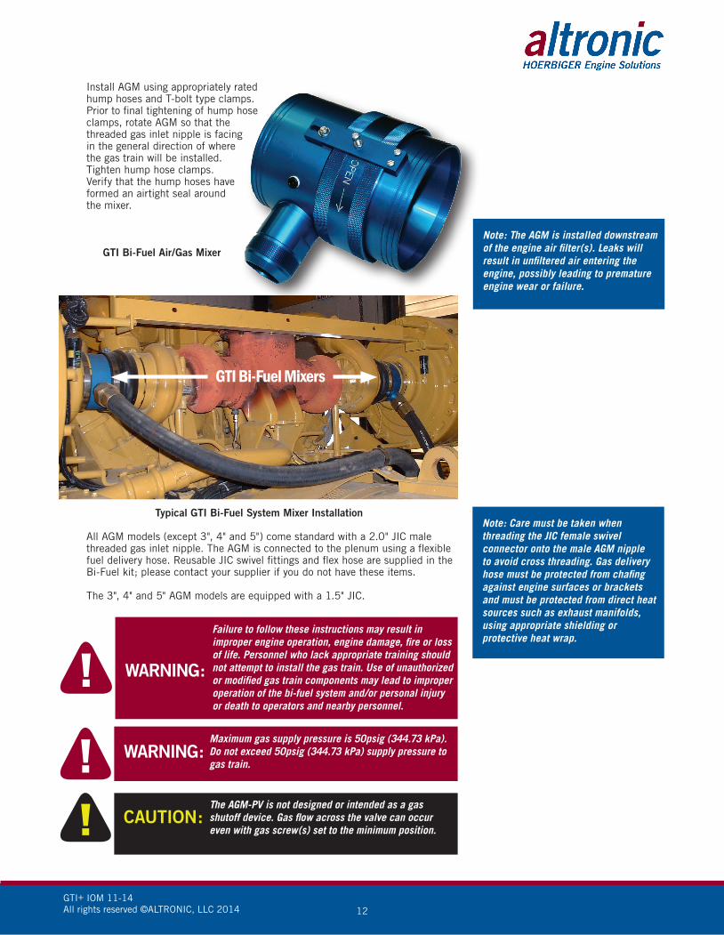
Install AGM using appropriately rated hump hoses and T-bolt type clamps. Prior to final tightening of hump hose clamps, rotate AGM so that the threaded gas inlet nipple is facing in the general direction of where the gas train will be installed. Tighten hump hose clamps. Verify that the hump hoses have formed an airtight seal around the mixer.
GTI Bi-Fuel Air/Gas Mixer
Typical GTI Bi-Fuel System Mixer Installation
All AGM models (except 3", 4" and 5") come standard with a 2.0" JIC male threaded gas inlet nipple. The AGM is connected to the plenum using a flexible fuel delivery hose. Reusable JIC swivel fittings and flex hose are supplied in the Bi-Fuel kit; please contact your supplier if you do not have these items.
The 3", 4" and 5" AGM models are equipped with a 1.5" JIC.
Note: The AGM is installed downstream of the engine air filter(s). Leaks will result in unfiltered air entering the engine, possibly leading to premature engine wear or failure.
Note: Care must be taken when threading the JIC female swivel connector onto the male AGM nipple to avoid cross threading. Gas delivery hose must be protected from chafing against engine surfaces or brackets and must be protected from direct heat sources such as exhaust manifolds, using appropriate shielding or protective heat wrap.
Failure to follow these instructions may result in improper engine operation, engine damage, fire or loss of life. Personnel who lack appropriate training should not attempt to install the gas train. Use of unauthorized or modified gas train components may lead to improper operation of the bi-fuel system and/or personal injury or death to operators and nearby personnel.
WARNING:
Maximum gas supply pressure is 50psig (344.73 kPa). Do not exceed 50psig (344.73 kPa) supply pressure to gas train.
WARNING:
The AGM-PV is not designed or intended as a gas shutoff device. Gas flow across the valve can occur even with gas screw(s) set to the minimum position.
CAUTION:
GTI+ IOM 11-14All rights reserved ©ALTRONIC, LLC 2014 13
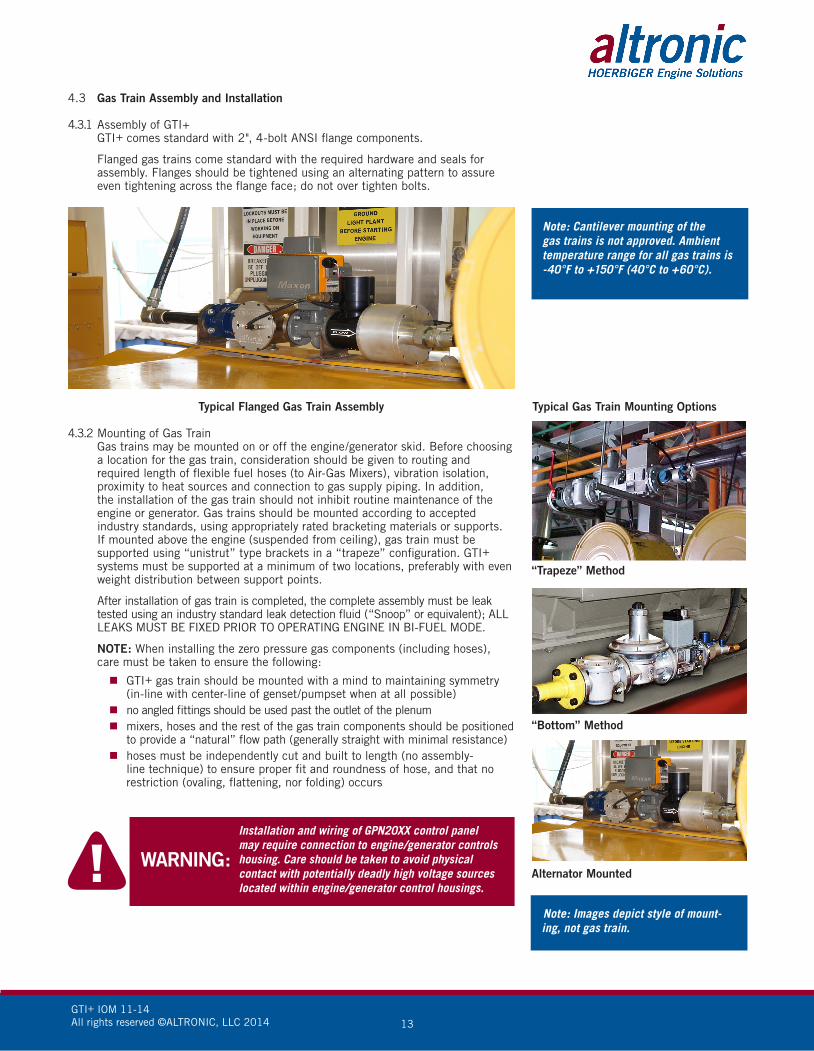
4.3 Gas Train Assembly and Installation
4.3.1 Assembly of GTI+ GTI+ comes standard with 2", 4-bolt ANSI flange components.
Flanged gas trains come standard with the required hardware and seals for assembly. Flanges should be tightened using an alternating pattern to assure even tightening across the flange face; do not over tighten bolts.
Typical Flanged Gas Train Assembly
4.3.2 Mounting of Gas Train Gas trains may be mounted on or off the engine/generator skid. Before choosing
a location for the gas train, consideration should be given to routing and required length of flexible fuel hoses (to Air-Gas Mixers), vibration isolation, proximity to heat sources and connection to gas supply piping. In addition, the installation of the gas train should not inhibit routine maintenance of the engine or generator. Gas trains should be mounted according to accepted industry standards, using appropriately rated bracketing materials or supports. If mounted above the engine (suspended from ceiling), gas train must be supported using “unistrut” type brackets in a “trapeze” configuration. GTI+ systems must be supported at a minimum of two locations, preferably with even weight distribution between support points.
After installation of gas train is completed, the complete assembly must be leak tested using an industry standard leak detection fluid (“Snoop” or equivalent); ALL LEAKS MUST BE FIXED PRIOR TO OPERATING ENGINE IN BI-FUEL MODE.
NOTE: When installing the zero pressure gas components (including hoses), care must be taken to ensure the following:
GTI+ gas train should be mounted with a mind to maintaining symmetry (in-line with center-line of genset/pumpset when at all possible)
no angled fittings should be used past the outlet of the plenum mixers, hoses and the rest of the gas train components should be positioned
to provide a “natural” flow path (generally straight with minimal resistance) hoses must be independently cut and built to length (no assembly-
line technique) to ensure proper fit and roundness of hose, and that no restriction (ovaling, flattening, nor folding) occurs
Installation and wiring of GPN20XX control panel may require connection to engine/generator controls housing. Care should be taken to avoid physical contact with potentially deadly high voltage sources located within engine/generator control housings.
WARNING:
Note: Cantilever mounting of the gas trains is not approved. Ambient temperature range for all gas trains is -40°F to +150°F (40°C to +60°C).
Typical Gas Train Mounting Options
“Bottom” Method
“Trapeze” Method
Alternator Mounted
Note: Images depict style of mount-ing, not gas train.

GTI+ IOM 11-14All rights reserved ©ALTRONIC, LLC 2014 14
4.4 Control Panel Installation Controls for GPN20XX models are housed in stainless steel enclosures. The
control panel is equipped with LED indicators mounted on front and a DE Power/Terminal Module mounted inner panel.
The control panel can be installed directly on the engine/generator skid or on an adjacent wall. In some cases, the control panel may be suspended from the ceiling using “unistrut” type support structure. Location of panel should allow for easy access to the control keypad and manual on-off switch as well as good visibility of panel LED indicator lights and LCD displays, while avoiding direct sunlight. Consideration should also be given to the various distances to each engine/gas train sensor and routing requirements of the sensor wiring harnesses. The control panel should not be mounted in close proximity to hot engine surfaces such as exhaust manifolds or mufflers. If the control panel is mounted on the engine/generator skid, suitable vibration isolators should be used to protect the control panel from excessive vibration.
The GPN20XX series panels require a 24VDC power supply (rated at 10AMPS). The panel provides DC power to the gas control solenoid valve and AGV5-2L during Bi-Fuel operation. In most applications, the panel is connected to a continuous DC power supply. This is done so that logged fault messages are not lost after engine shutdown. In order to prevent the possibility of the control panel activating the gas solenoid valve when the engine is not running, Bi-Fuel inhibit terminals are provided for a separate “engine run” or “breaker closed” permissive. When this feature is used, the control panel cannot activate Bi-Fuel operation without a contact closure at these terminals. The GTI 20XX panels are protected by a special type of 5 AMP very fast-acting fuse (P/N 611129). Theses fuses are exponentially faster than standard off-the-shelf fast-acting fuses, and help protect key components inside the panel. Therefore it is important to only use the GTI specified part.
4.5 Engine Sensor Installation
4.5.1 Exhaust Gas Temperature (EGT) Thermocouple P/N 610861-XX and (610862 compression fitting) The EGT thermocouple is installed in the engine exhaust system. One
thermocouple should be mounted per primary turbo. Typical mounting locations include the exhaust manifold, turbocharger exhaust outlet or exhaust collector pipe. In all cases, the EGT thermocouple should be installed as close to the turbo as possible and should not be installed downstream of the exhaust silencer. Standard, one to four separate EGT thermocouples may be installed. Each EGT thermocouple is supplied with a bore-through type adaptor with 1/8" male NPT threads.
4.5.2 Manifold Air Temperature (MAT) Thermocouple P/N 610861-XX and (610862 compression fitting) The MAT thermocouple is installed in the engine air-intake system. The
thermocouple should be mounted AFTER the turbo-compressor, in a position where it can sense the temperature of the combustion air. For engines with charge-air cooling systems, the sensor should be installed AFTER the aftercooler so that the temperature of the air entering the cylinders can be measured. Standard, one to four separate MAT thermocouples may be installed. Each MAT hermocouple is supplied with a bore-through type adaptor consisting of a 1/8” male NPT thread and compression fitting. NOTE: Care should be taken when selecting a mounting location for MAP. Radiant heat from the exhaust manifold could damage the transducer.
4.5.3 Manifold Air Pressure MAP Transducer P/N 691201-50 The MAP transducer is installed downstream of the turbocharger outlet
(pressure side) in order to sense manifold air pressure (turbo boost). Standard one to four MAP transducers may be installed. For engines with charge air cooling systems, the MAP transducer should be installed AFTER the cooling circuit in order to decrease the operating temperature of the transducer. Remote-mounting of the MAP transducer will be required if operating temperatures will exceed 200°F (93°C).
Note: All harnesses should be cut-to-length and routed away from the alternator and/or any RFI/EMI source. A suitable ground may need to be tied between the panel and engine block to eliminate any interference.
Note: For detailed information on DE, please see appropriate Operating Manual.
Note: GTI 20XX panels are protected with special fuses. For replacement of fuses, P/N 611129 can be ordered from Altronic.
Exhaust Gas Temperature (EGT) Thermocouple
Manifold Air Temperature (MAT) Thermocouple

GTI+ IOM 11-14All rights reserved ©ALTRONIC, LLC 2014 15
4.5.4 Engine Vacuum (VAC) Transducer (P/N 691206-50) The VAC transducer measures the vacuum signal in the
air intake system between the air cleaner and AGM inlet. Standard, one to four vacuum transducers may be installed.
4.5.5 Vibration (VIB) Transducer (P/N 691205) The VIB transducer is mounted on the engine deck or
cylinder head using the supplied heat-sink adaptor. The heat sink adaptor is supplied with a 3/8"-16 thread stud for mounting to engine. VIB comes standard with a 2 conductor connectorized pigtail. Terminate VIB wiring harness mating connector to connector on VIB sensor.
Note 4-20mA must have jumper in place.
If possible, the VIB transducer should be mounted in the same plane as the engine cylinders. For single VIB installations, mount the transducer on either end of engine. For dual VIB installations, mount the transducers on opposite corners of engine (diagonally opposed).
4.5.6 Gas Supply Pressure (GSP) Transducer (P/N 691201-50) GSP transducer is mounted in one of the available
OUTLET pressure ports located on the gas filter. Pressure drop across the filter may be determined by comparing GSP (as displayed on Bi-Fuel Control Panel) to the upstream supply pressure (as measured with a mechanical pressure gauge). Adaptor fitting (P/N 610879) and gasket (P/N 610880) are provided in the Panel Accessory Kit for mounting of the GSP transducer.
4.5.7 kW The kW sensor is composed of three parts: WT (Watt transducer), CT (Current
Transformer), and PT (Potential Transformer–used on 600V alternators). The WT should be mounted inside of the alternator housing. The CT is of split core design and is to be opened in a twisting motion only. The CT is also current directional. The CT should be installed before the alternator buss bars. The PT should be installed close to the WT. The PT steps down 600V to 240V for the WT. The PT is only used on 600V systems. Contact Master Distributor for sizes available.
Note 4-20mA must have jumper in place.
4.5.8 AGV Output Pressure (CH28) The AGV5-2L output pressure sensor is mounted in one of the two available
1/8" NPT ports so it can sense gas supply pressure to the engine. The sensor is 1/8" NPT and is ONLY to be installed on one AGM-PV.
4.5.9 RPM RPM requires the use a MAG PICKUP. The channel requires the input of PPR
(Pulses Per Revolution), also know as Gear Tooth Count in the configuration screen.
4.5.10 AUX Channels The DE3020 can monitor up to six auxiliary channels (29-34). These channels
can be configured to accept 4-20 mA, 0-5 VDC, J or K thermocouple, and normally open or closed inputs.
In order to utilize any of the AUX channels, dip switches on the terminal board must me set to the correct positions and the channel(s) activated through the terminal program.
Kilowatt Sensor Installation
GTI+ IOM 11-14All rights reserved ©ALTRONIC, LLC 2014 16
The six auxiliary channel labels can be configured through the terminal program to read up to 10 characters on the DE display.
Note: If four VIB sensors are used, channels 29 and 30 can reference the VIB delay timer.
4.6 Wiring Wire harnesses from the control panel to left bank, right bank (if applicable),
fuel train, and power source are furnished with the GTI Bi-Fuel kit.
Refer to the appropriate operating manual for detailed wiring information.
Harnesses should be installed in the proper control panel entrance hole and properly terminated within the control panel. They should be routed to the locations of the sensors and power source, using care to avoid routing near excessively hot surfaces or surfaces which will vibrate and chafe the harnesses.
Failure to follow these instructions may result in improper engine operation and/or engine damage. Bi-fuel setup is restricted to qualified personnel only.
WARNING:
5.0 ENGINE SETUP AND OPERATION
5.1 General Requirements and Considerations A load bank with metering or equivalent means of setting a controlled/stable
load on the generator/pump, variable throughout its full range of operation (0 to 100% of rated load) in repeatable 5 to 10% of rated load increments.
High quality digital multi-meter, differential pressure manometer, and basic hand tools.
A reliable and accurate method of measuring real-time diesel fuel consumption throughout the commissioning process and full range of operation (0 to 100% of rated load).
5.1.1 Engine Condition: Prior to commencing the bi-fuel setup process, a thorough check of engine operation on 100% diesel fuel should be performed. This check should include all major engine systems (cooling, lubrication, fuel, charge-air cooling, air intake, safety, etc.) for proper operation and condition. It is required that a load test of 0-100% load in 10% increments be conducted to verify that the engine performs according to specifications. All outstanding maintenance and/or performance items should be addressed prior to running the engine in Bi-Fuel mode.
5.1.2 Estimating Gas-Diesel Ratio: Altronic-GTI is able to provide fuel flow meters for purchase. If the engine is not equipped with fuel flow metering, and a fuel flow meter is not purchased, GTI has developed a reliable method of adjusting gas-diesel ratio based on information from the engine fuel governing system. All constant speed diesel engines utilize some form of fuel control system which varies diesel fuel flow in response to load change, in order to maintain the desired engine speed. Control methods commonly used include mechanical fuel racks, fuel rail pressure regulators or electronic injection. Regardless of the type of fuel control system used, the basic operating theory is the same; diesel flow is controlled in a linear manner from 0% flow (engine off) to 100% flow (full load). For a given load condition, the governor will adjust between the 0% and 100% fuel limits in order to maintain engine speed; this value is generally referred to as “rack position” or “fuel position”. Other things being equal, for a given engine load there will be a definite rack position and therefore a definitive diesel fuel flow.
During bi-fuel operation at a given load, the governor will retard the rack position (i.e., diesel fuel flow) relative to the amount of gas that is being supplied to the engine, in order to maintain the set speed. Since this retarded rack position can be correlated to a specific engine load (and vice versa), the
NOTE: All furnished drawings and instructions assume (–) ground DC system. In the case of a floating ground, or (+) ground DC system, please contact Altronic Factory for support.
Note: this method is not always available.

GTI+ IOM 11-14All rights reserved ©ALTRONIC, LLC 2014 17
diesel fuel flow, and therefore the gas-diesel ratio, can be calculated with good accuracy. In practice, a “reference load” is calculated at which the diesel fuel flow and rack position are equal to the diesel portion of the target gas-diesel ratio. For example, if a 60% gas mixture is desired for a genset operating at 1200kWe, the reference load would be 480kWe (1200 x .40 = 480kWe). The engine is then loaded to 480kWe and the rack position is noted. The engine is then loaded to 1200kWe and the gas ratio adjusted such that the rack position (i.e., diesel fuel flow) is equivalent to the 480kWe load level.
At this point, the engine would be producing 1200 kWe while using the diesel fuel required to make 480kWe, i.e., the balance is being made up with the gas, and the engine is operating at a fuel ratio of approximately 60% gas and 40% diesel fuel.
5.1.3 Measurement of Engine Power: For electrical generator applications, engine power may be measured in electric kilowatts (kWe) and/or Amps. For pump or compressor applications, it may be necessary to calculate engine load based on MAP (manifold air pressure) or pump/compressor load.
5.1.4 Methods of Measuring Rack Position: In order to adjust the Bi-Fuel System to achieve the desired gas-diesel ratio, it will be necessary to measure the “rack position” or “fuel position” of the diesel injection system at a given engine load. The following techniques can be used:
Measurement of control signal from governor to actuator (electronic governors such as Woodard 2301). This can be taken using a digital multimeter installed in series between the governor control module (“ACT” contact) and actuator. This value is typically measured in milliamps (mA).
Measurement of “fuel position” or “injector duration” (electronic diesel engines such as Caterpillar B Series). This typically requires the use of proprietary engine diagnostic software (provided by engine manufacturer) and either a laptop computer or hand-held diagnostic tool.
Measurement of physical position of diesel fuel rack (rack %). Depending on design of the fuel system, it may be possible to measure rack travel directly, using calipers, index, etc. Since total rack travel from 0% to 100% is typically a short distance, this measurement must be made with a high degree of accuracy.
5.2 Establishing Target Bi-Fuel Operating Values
5.2.1 Target Bi-Fuel Gas-Diesel Ratio: The gas substitution that is possible varies depending on gas quality, engine design, engine model and condition, engine load factor, charge air temperature (aftercooling), and ambient conditions (altitude and temperature), but should never exceed 70%, even under the most ideal conditions. In general, high quality gas (over 95% CH4), combined with moderate engine power levels and low temperature aftercooling will typically yield gas ratios in the 60% to 70% range, although there are factors that can still limit this value to much lower levels. Lower quality gas, combined with high manifold air temperature (MAT) and/or higher engine loads, will typically result in gas substitution closer to 50%. OEM engine control strategy can also result in limitations in the achievable substitution rate. The final gas ratio will be determined during the commissioning process and may be higher or lower than the target value, based on knock limits, engine exhaust temperatures, and/or other operating factors.
Knock Limit: In most applications, engine knock (detonation) will be the limiting factor in determining maximum gas ratio. In most cases, short duration knock will not cause harm to the engine, however, extended operation in a knocking condition may result in engine damage or failure. A knocking condition can be diagnosed both audibly and using the Bi-Fuel System vibration sensor (VIB) data. Data from the engine vibration sensors (if installed) should be monitored closely during the setup procedure to confirm proper engine operation. If knocking is detected during bi-fuel operation, the engine should be rapidly switched to 100% diesel operation. To prevent recurrence of knocking, a reduction in gas ratio will be required.
Note: Engine must be equipped with a full authority governor to operate properly with the GTI Bi-Fuel system.
Note: For electronic diesel engines using ECU control of injection timing and duration, DO NOT USE COMPUTED FUEL FLOW AS REFERENCE. The fuel flow data from the ECU is derived from calculations based on various engine data (not from fuel flow meters) and may not be accurate while engine is operating in bi-fuel mode. “Injector duration” and/or “fuel position” data will be accurate during both diesel and bi-fuel modes.
GTI+ IOM 11-14All rights reserved ©ALTRONIC, LLC 2014 18
5.2.2 Target Bi-Fuel Maximum Load Rating: Engines converted to GTI+ Bi-Fuel are typically utilized for drilling rig or high transient load applications. It is important for the installing technician to understand the power rating system used for most high-speed diesel engines, and the associated duty-cycles applicable to each. Most manufacturers of high speed (1200–1800rpm) diesel engines and generator sets publish stand-by, prime and continuous ratings. The stand-by rating is reserved for emergency operation only and represents the highest HP or kWe level that can be sustained for a limited period of time. In most applications, the stand-by rating will not be used for bi-fuel operation. The prime rating typically allows for unlimited hours of use, with a variable load, up to the prime rated output. The continuous rating is the most conservative rating, and is reserved for unlimited hours at a constant load. In general, bi-fuel mode is reserved for operations at or below the prime rating of the machine. The higher the number of hours of intended use, and the more constant the load rate, the more conservative the rating should be. For baseload type operations, GTI recommends a rating of 80% of continuous for bi-fuel mode.
5.3 Setup Procedure Before proceeding with the setup, the installing technician should be
familiar with operation of the Bi-Fuel Electronic Control Panel and controller programming procedures.
Programming instructions, which also allow the user to configure, calibrate, and switch from English to Metric units, are contained within the “Programming” section of the Controller Operating Manual. Terminal program software is supplied by the Master Distributor and requires use of a standard Personal Computer (PC) as the interface device. Program load can be checked by sequencing through the channels on the Display and verifying that sensor data and all appropriate channels are being displayed. All GPN20XX panels are shipped with factory default settings for all control and safety setpoints. This configuration can be changed using the appropriate terminal software. A complete listing of the default settings and configurations is available in Figure 1 of the GPN manual.
The following procedure is a guideline to system setup and commissioning.
Direct any questions to your Master Distributor.
1. Collect Diesel Only Baseline Engine Data TURN THE MANUAL GAS VALVE TO THE OFF POSITION. TURN THE
AGM-PV TO THE FULLY-CLOSED POSITON. Turn the Bi-Fuel control panel power switch to the ON position; place the panel in MANUAL STOP, complete DIESEL ONLY baseline, 0-100% load in 10% steps. Record data on the Bi-Fuel Commissioning Form. Edit safety and control points to working values.
IMPERATIVE: an electrical load bank with means of metering or equivalent means of setting a controlled/stable load on the (power pack) generator set, variable throughout its full range of operation (0-100% of rated load) in repeatable 5-10% of rated load steps, must be used. A reliable and accurate method of measuring real-time diesel fuel consumption throughout the commissioning process and full range of operation (0-100% of rated load) is required to comply with commissioning processes.
2. Reduce Engine Load to 0%
3. Set Initial MAP “Control Setpoints” in Bi-Fuel Control Panel Set MAP “Low” and MAP “High” Control Setpoints to turn bi-fuel on/off
in desired load window. MAP Control Setpoints will be re-adjusted at the conclusion of the setup procedure.
4. Set Initial kW “Control Setpoints” in Bi-Fuel Control Panel Set kW “low” and kW “HIGH” Control Setpoints to match the desired load
window. Bi-fuel will not turn on outside of the controlled window.
Note: The engine-generator is not de-rated by the Bi-Fuel System. Higher engine power levels are still available to the user (above the Bi-Fuel rating) as the Bi-Fuel System will automati-cally transition the engine to 100% diesel mode if the power level rises above the limit programmed in the electronic control panel. GTI has seen a willingness on the part of some users to operate their engines at load levels inconsistent with long term engine durability. It must be stressed to the operator that high speed diesel engines will incur significant main-tenance expenses if operated at high load levels for long periods, regard-less of whether operating on Bi-Fuel or 100% diesel mode.
Note: For collecting baseline engine data, the manual gas valve MUST be in the OFF position and the GTI panel MUST be in the MANUAL STOP mode.
Note: All setpoints must be reviewed for correct values based on the application. Default values are not adequate and will not shut bi-fuel off in an unsafe condition.

GTI+ IOM 11-14All rights reserved ©ALTRONIC, LLC 2014 19
5. Set GSP, VAC, MAT, EGT, and VIB “Control Setpoints” Adjust the Control Setpoints for EGT, MAT, VIB, VAC and GSP channels to
the minimum and maximum values (low and high setpoint span values). This will prevent unwanted “Control” shutdowns of the Bi-Fuel System.
6. Set Initial “Safety Setpoints” in Bi-Fuel Control Panel With the Bi-Fuel Control Panel in “manual stop”, set the EGT, MAT and
VIB “high” limits to 1.05 times the values recorded in step 1. Set the EGT, MAT and VIB “low” limits to the minimum allowable value. For VAC, set the “low” limit value to -0.2psig (100kPa) of the value recorded in step 1. Set the VAC “high”, limit to the maximum allowable value.
7. Check “Bi-Fuel Inhibit” Contact Check Bi-Fuel Inhibit contact. If this feature is not being used, confirm
that jumper has been installed (DE-3020 Terminal 13 (+ to -)).8. Verify Engine Governor “Gain” Setting Governor gain should be set at approximately 70%-80% for optimal bi-
fuel operation. Higher gain settings may cause engine instability during transition from diesel mode to bi-fuel mode and vice-versa.
9. Reset Bi-Fuel Control Panel – Verify Control Status With the engine outside of the bi-fuel load window, manually reset the
Bi-Fuel Control Panel. Verify that Bi-Fuel Controller is in Control Shutdown mode (both red and green status LED’s are off, BI-FUEL OFF showing on top of display.
10. Increase Engine Load to LOW Bi-Fuel Window
As gas ratio is increased, it is the responsibility of the installing technician to constantly monitor engine performance and behavior using data provided by the Bi-Fuel Control Panel and/or engine/generator control panel as well as audible engine noise.
CAUTION:
Note: There may be reasons to use these channels as a Control Set point. All channels can be configured to be used as a Control and Safety.
Note: The factory default low MAP CONTROL and SAFETY setpoint is 20 psi. As a result, the installer must ad-just these setpoints before the bi-fuel mode can be activated.
Note: It may not be possible to reach desired gas ratio at target bi-fuel rating. If target gas ratio cannot be reached safely, it will be necessary to decrease gas ratio or decrease target bi-fuel load rating. It is recommended that new air filters be installed
before a GTI+ system is commissioned.CAUTION:
GTI+ IOM 11-14All rights reserved ©ALTRONIC, LLC 2014 20
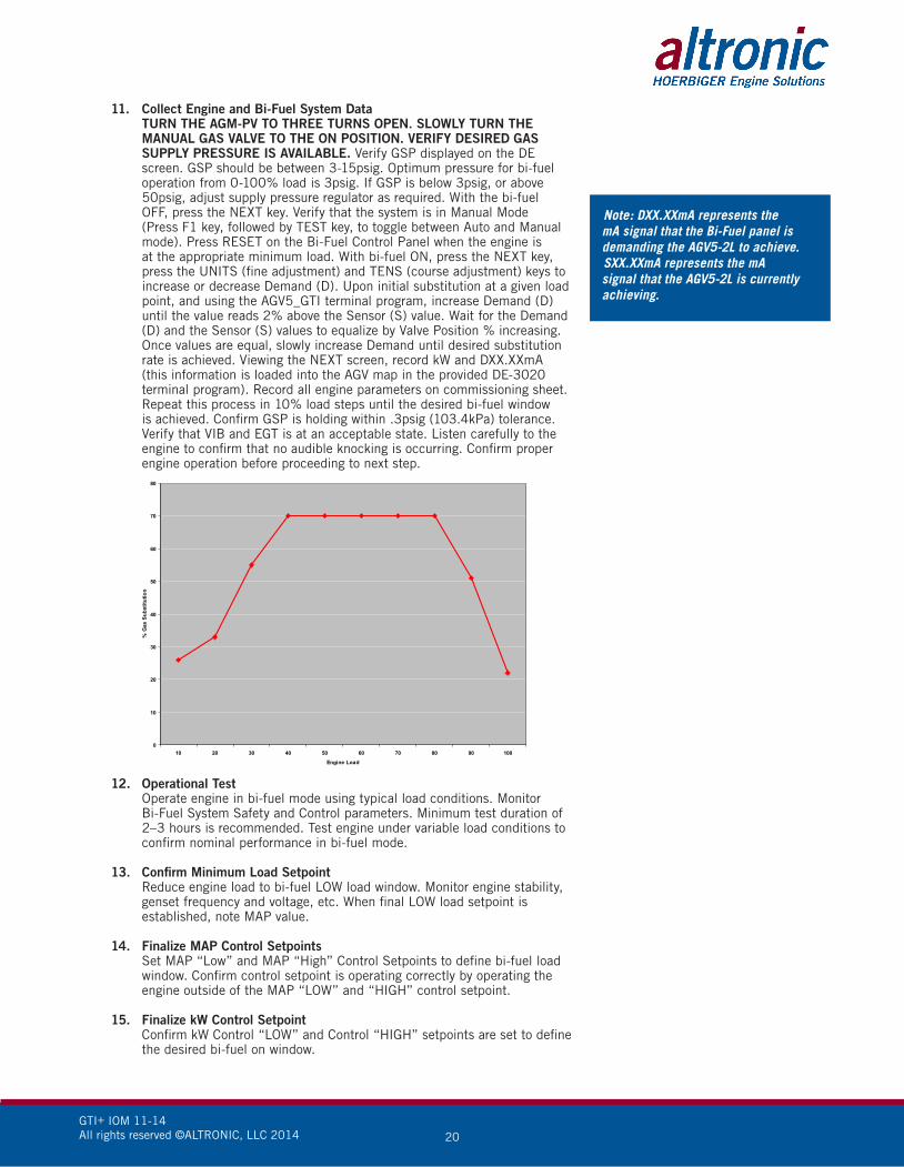
11. Collect Engine and Bi-Fuel System Data TURN THE AGM-PV TO THREE TURNS OPEN. SLOWLY TURN THE
MANUAL GAS VALVE TO THE ON POSITION. VERIFY DESIRED GAS SUPPLY PRESSURE IS AVAILABLE. Verify GSP displayed on the DE screen. GSP should be between 3-15psig. Optimum pressure for bi-fuel operation from 0-100% load is 3psig. If GSP is below 3psig, or above 50psig, adjust supply pressure regulator as required. With the bi-fuel OFF, press the NEXT key. Verify that the system is in Manual Mode (Press F1 key, followed by TEST key, to toggle between Auto and Manual mode). Press RESET on the Bi-Fuel Control Panel when the engine is at the appropriate minimum load. With bi-fuel ON, press the NEXT key, press the UNITS (fine adjustment) and TENS (course adjustment) keys to increase or decrease Demand (D). Upon initial substitution at a given load point, and using the AGV5_GTI terminal program, increase Demand (D) until the value reads 2% above the Sensor (S) value. Wait for the Demand (D) and the Sensor (S) values to equalize by Valve Position % increasing. Once values are equal, slowly increase Demand until desired substitution rate is achieved. Viewing the NEXT screen, record kW and DXX.XXmA (this information is loaded into the AGV map in the provided DE-3020 terminal program). Record all engine parameters on commissioning sheet. Repeat this process in 10% load steps until the desired bi-fuel window is achieved. Confirm GSP is holding within .3psig (103.4kPa) tolerance. Verify that VIB and EGT is at an acceptable state. Listen carefully to the engine to confirm that no audible knocking is occurring. Confirm proper engine operation before proceeding to next step.
0
10
20
30
40
50
60
70
80
10 20 30 40 50 60 70 80 90 100
Engine Load
% G
as S
ubst
itutio
n
Note: DXX.XXmA represents the mA signal that the Bi-Fuel panel is demanding the AGV5-2L to achieve.SXX.XXmA represents the mA signal that the AGV5-2L is currently achieving.
12. Operational Test Operate engine in bi-fuel mode using typical load conditions. Monitor
Bi-Fuel System Safety and Control parameters. Minimum test duration of 2–3 hours is recommended. Test engine under variable load conditions to confirm nominal performance in bi-fuel mode.
13. Confirm Minimum Load Setpoint Reduce engine load to bi-fuel LOW load window. Monitor engine stability,
genset frequency and voltage, etc. When final LOW load setpoint is established, note MAP value.
14. Finalize MAP Control Setpoints Set MAP “Low” and MAP “High” Control Setpoints to define bi-fuel load
window. Confirm control setpoint is operating correctly by operating the engine outside of the MAP “LOW” and “HIGH” control setpoint.
15. Finalize kW Control Setpoint Confirm kW Control “LOW” and Control “HIGH” setpoints are set to define
the desired bi-fuel on window.
GTI+ IOM 11-14All rights reserved ©ALTRONIC, LLC 2014 21
Note: Failure to submit this form may void applicable warranties.
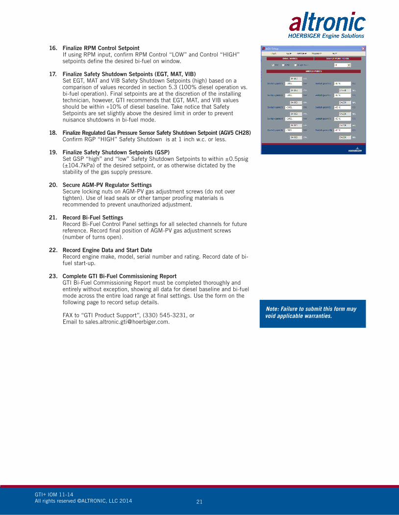
16. Finalize RPM Control Setpoint If using RPM input, confirm RPM Control “LOW” and Control “HIGH”
setpoints define the desired bi-fuel on window.
17. Finalize Safety Shutdown Setpoints (EGT, MAT, VIB) Set EGT, MAT and VIB Safety Shutdown Setpoints (high) based on a
comparison of values recorded in section 5.3 (100% diesel operation vs. bi-fuel operation). Final setpoints are at the discretion of the installing technician, however, GTI recommends that EGT, MAT, and VIB values should be within +10% of diesel baseline. Take notice that Safety Setpoints are set slightly above the desired limit in order to prevent nuisance shutdowns in bi-fuel mode.
18. Finalize Regulated Gas Pressure Sensor Safety Shutdown Setpoint (AGV5 CH28) Confirm RGP “HIGH” Safety Shutdown is at 1 inch w.c. or less.
19. Finalize Safety Shutdown Setpoints (GSP) Set GSP “high” and “low” Safety Shutdown Setpoints to within ±0.5psig
(±104.7kPa) of the desired setpoint, or as otherwise dictated by the stability of the gas supply pressure.
20. Secure AGM-PV Regulator Settings Secure locking nuts on AGM-PV gas adjustment screws (do not over
tighten). Use of lead seals or other tamper proofing materials is recommended to prevent unauthorized adjustment.
21. Record Bi-Fuel Settings Record Bi-Fuel Control Panel settings for all selected channels for future
reference. Record final position of AGM-PV gas adjustment screws (number of turns open).
22. Record Engine Data and Start Date Record engine make, model, serial number and rating. Record date of bi-
fuel start-up.
23. Complete GTI Bi-Fuel Commissioning Report GTI Bi-Fuel Commissioning Report must be completed thoroughly and
entirely without exception, showing all data for diesel baseline and bi-fuel mode across the entire load range at final settings. Use the form on the following page to record setup details.
FAX to “GTI Product Support”, (330) 545-3231, or Email to [email protected].
Note: Failure to submit this form may void applicable warranties.
12. Operational Test Operate engine in bi-fuel mode using typical load conditions. Monitor
Bi-Fuel System Safety and Control parameters. Minimum test duration of 2–3 hours is recommended. Test engine under variable load conditions to confirm nominal performance in bi-fuel mode.
13. Confirm Minimum Load Setpoint Reduce engine load to bi-fuel LOW load window. Monitor engine stability,
genset frequency and voltage, etc. When final LOW load setpoint is established, note MAP value.
14. Finalize MAP Control Setpoints Set MAP “Low” and MAP “High” Control Setpoints to define bi-fuel load
window. Confirm control setpoint is operating correctly by operating the engine outside of the MAP “LOW” and “HIGH” control setpoint.
15. Finalize kW Control Setpoint Confirm kW Control “LOW” and Control “HIGH” setpoints are set to define
the desired bi-fuel on window.
GTI+ IOM 11-14All rights reserved ©ALTRONIC, LLC 2014 22
6.0 CT AND WATT TRANSDUCER
Please follow the instructions below to properly specify the required CTs, PT and Watt Transducer.
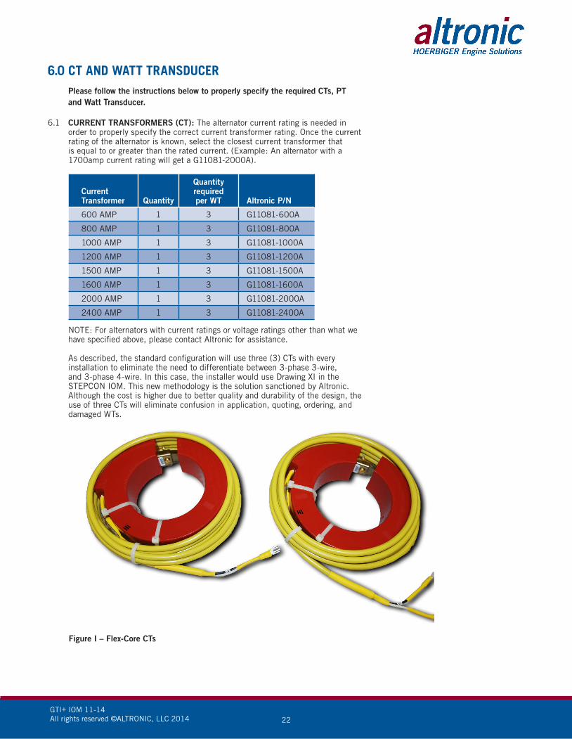
6.1 CURRENT TRANSFORMERS (CT): The alternator current rating is needed in order to properly specify the correct current transformer rating. Once the current rating of the alternator is known, select the closest current transformer that is equal to or greater than the rated current. (Example: An alternator with a 1700amp current rating will get a G11081-2000A).
CurrentTransformer Quantity
Quantity requiredper WT Altronic P/N
600 AMP 1 3 G11081-600A
800 AMP 1 3 G11081-800A
1000 AMP 1 3 G11081-1000A
1200 AMP 1 3 G11081-1200A
1500 AMP 1 3 G11081-1500A
1600 AMP 1 3 G11081-1600A
2000 AMP 1 3 G11081-2000A
2400 AMP 1 3 G11081-2400A
NOTE: For alternators with current ratings or voltage ratings other than what we have specified above, please contact Altronic for assistance.
As described, the standard configuration will use three (3) CTs with every
installation to eliminate the need to differentiate between 3-phase 3-wire, and 3-phase 4-wire. In this case, the installer would use Drawing XI in the STEPCON IOM. This new methodology is the solution sanctioned by Altronic. Although the cost is higher due to better quality and durability of the design, the use of three CTs will eliminate confusion in application, quoting, ordering, and damaged WTs.
Figure I – Flex-Core CTs
GTI+ IOM 11-14All rights reserved ©ALTRONIC, LLC 2014 23
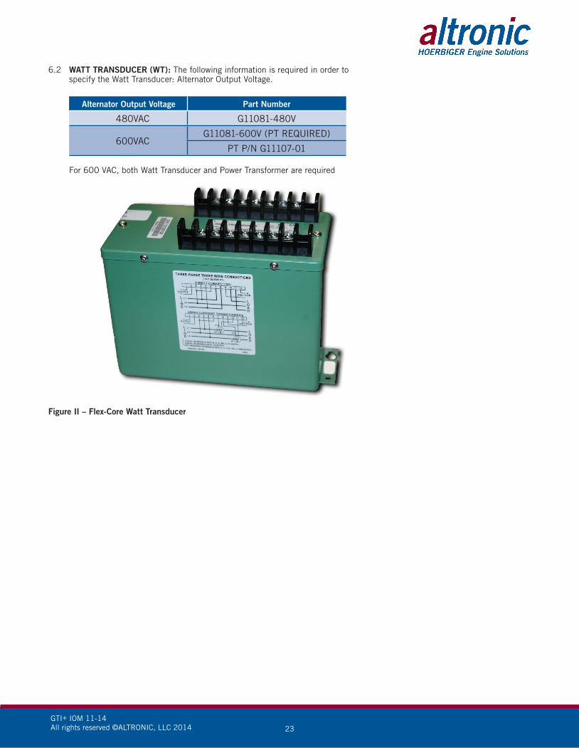
6.2 WATT TRANSDUCER (WT): The following information is required in order to specify the Watt Transducer: Alternator Output Voltage.
Alternator Output Voltage Part Number
480VAC G11081-480V
600VACG11081-600V (PT REQUIRED)
PT P/N G11107-01
For 600 VAC, both Watt Transducer and Power Transformer are required
Figure II – Flex-Core Watt Transducer

GTI+ IOM 10-13 GTI Bi-Fuel® Installation & Operating Manual All rights reserved © ALTRONIC, LLC 2013 24
MD:
Inst
alle
r:U
nit #
:
Date
2127
2829
3031
3233
34GS
PkW
AGV
AUX1
AUX2
AUX3
AUX4
AUX5
AUX6
FCEC
TO
PEG
TTi
me
AA
CA
CA
CA
C1L
1RB
DB
DB
DB
DRP
M%
#DIV
/0!
#DIV
/0!
#DIV
/0!
#DIV
/0!
#DIV
/0!
#DIV
/0!
#DIV
/0!
#DIV
/0!
#DIV
/0!
#DIV
/0!
#DIV
/0!
Safe
ty L
ow
ROP
Setp
oint
:
Page
OF
Appl
icat
ion:
SUB
25 EGT
ECM
22 VAC
23 MAP
24 MAT
Com
miss
ione
d By
:
Altr
onic
App
rova
l:
Appr
oval
Sta
mp
Tach
= T
acho
met
er
SV =
Sol
enoi
d Va
lve
VIB
= En
gine
Vib
ratio
n
VAC
= Ai
r Filt
er V
accu
m
Mix
er 5
Tur
ns:
TACH
Syst
em M
odel
:
Loca
tion:
Cont
rol L
ow
Cont
rol H
igh
Safe
ty h
igh
SUB
= Su
bstit
utio
n
24 MAT
25
FC =
Fue
l Con
sum
pton
OT
= O
il Te
mp
ENG
= En
gine
GSP
= Ga
s Sup
ply
Pres
sure
Mix
er 2
Tur
ns:
Mix
er 3
Tur
ns:
Mix
er 4
Tur
ns:
kW H
yste
resis
:
ZPR
Pres
sure
:
MD
= M
aste
r Dist
ribut
or
MDL
= M
odel
OP
= O
il Pr
essu
re
Gen
MDL
/ S
/N:
Eng
Hour
s:
Paka
ge R
atin
g:
Eng
MDL
/ S
/N:
kW =
Kilo
wat
t
MAP
= M
anifo
ld A
ir Pr
essu
re
D= D
iese
l Fue
l
ECM
= E
ngin
e Co
ntro
ller M
odul
e
ECT
= En
gine
Coo
lant
Tem
p
EGT
= Ex
haus
t Gas
Tem
p
D or B
22 VAC
23 MAP VI
B Ti
mer
:
Bi-F
uel D
elay
:
MAP
Hys
tere
sis:
EGT
26 VIB
Disp
lay
S/N
:
Term
inal
S/N
:
Not
es:
Aver
age
Load
:
OEM
MAX
MAT
:
OEM
MAX
EGT
:
OEM
MAX
MAP
:
ZPR
Turn
s In:
Mix
er 1
Tur
ns:
ZPR
= Ze
ro P
ress
ure
Regu
lato
r
Mix
er 6
Tur
ns:
MAT
= M
anifo
ld A
ir Te
mp
ROP
= Re
gula
ted
Out
put P
ress
ure
S/N
= S
eria
l Num
ber
B =
Bi-F
uel
Loca
tion
Seal
#
Term
inal
Firm
war
e Da
te:
Disp
lay
Firm
war
e Da
te:
Cust
omer
Acc
epta
nce:
GTI+ IOM 11-14All rights reserved ©ALTRONIC, LLC 2014 25
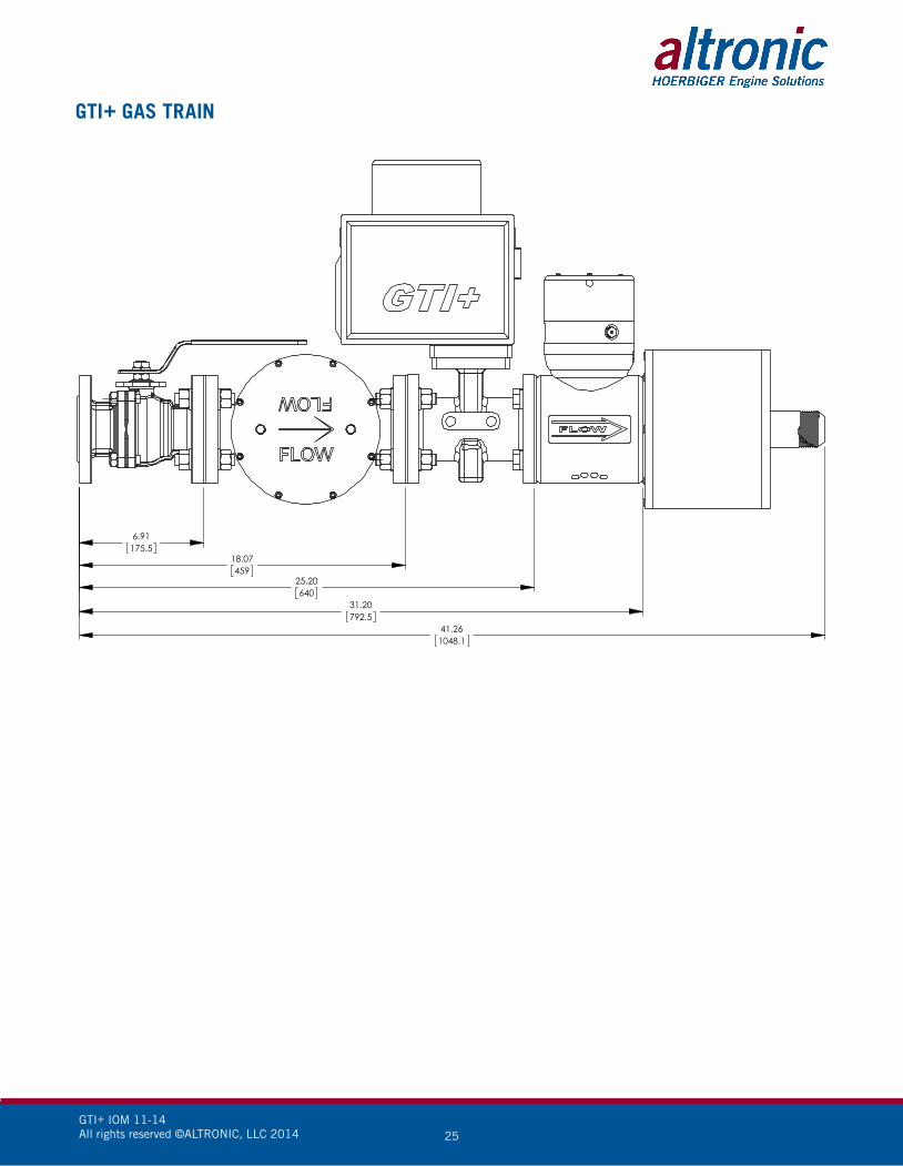
GTI+ GAS TRAIN
41.261048.1
6.91175.5
18.07459
25.20640
31.20792.5

GTI+ IOM 11-14All rights reserved ©ALTRONIC, LLC 2014 26
GTI+ GAS TRAIN
DESCRIPTION PART NUMBER QTY. HOSE SIZE
SHUTOFF BALL VALVE G11010-KT 1 OPTIONAL
GAS FILTER GFL006 1
SHUTOFF VALVE GSV012 1
ELECTRONIC REGULATOR AGV5-2L 1
PLENUM GPV009-KT 1
INLET PLENUM PLATE G90020 1
HARDWARE G11002 4
GASKETS G12022 5
APPLICABLE PLENUM PLATES
9" PLATE ONE 2" JIC OUTLET G9120 1
9" PLATE TWO 2" JIC OUTLETS G9220 1
9" PLATE FOUR 2" JIC OUTLETS GP420 1
12" PLATE SIX 2" JIC OUTLETS G12620 1
MIXERS
3" - 1.5" MALE JIC GMX0030-PV
4" - 1.5" MALE JIC GMX0040-PV
5" - 1.5" MALE JIC GMX0050-PV
6" - 2" MALE JIC GMX0060-PV
7" - 2" MALE JIC GMX0070-PV
8" - 2" MALE JIC GMX0080-PV
CUSTOM SIZE CONTACT FACTORY
FITTINGS/ADAPTERS
1.5" JIC FITTING G11063 1.5
2" JIC FITTING G11072 2
2" JIC FEMALE X 1.5" JIC MALE ADAPTER G11122 1.5

GTI+ IOM 11-14All rights reserved ©ALTRONIC, LLC 2014 27
WIRING SCHEMATIC
RGP AGV WhiteRGP AGV Black
NOTE: ALL 4-20mA sensors keep jumper in place.
GTI+ IOM 11-14All rights reserved ©ALTRONIC, LLC 2014 28
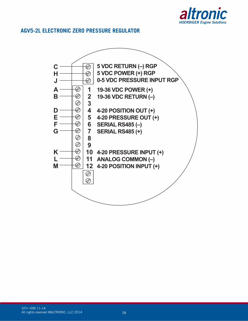
AGV5-2L ELECTRONIC ZERO PRESSURE REGULATOR
AB
DEFG
KLM
CHJ
123456789101112
19-36 VDC POWER (+)19-36 VDC RETURN (–)
4-20 POSITION OUT (+)4-20 PRESSURE OUT (+)SERIAL RS485 (–)SERIAL RS485 (+)
4-20 PRESSURE INPUT (+)ANALOG COMMON (–)4-20 POSITION INPUT (+)
5 VDC RETURN (–) RGP5 VDC POWER (+) RGP0-5 VDC PRESSURE INPUT RGP

GTI+ IOM 11-14All rights reserved ©ALTRONIC, LLC 2014 29
WIRING DIAGRAM – SENSOR TERMINAL
AUX +
GSP1 - RED
VAC (1,3 ) - REDMAP (1,3 ) - REDAUX2, AGVRGP - REDAUX3
VIB1, 2L +
AUX4 +VAC (2,4) - REDMAP (2,4) - REDAUX5 +
VIB1, 2R +AUX6 +AUX7 +
AUX8 +
SK208712-19-13
FUELHARNESS
BLUE
LEFTBANK
ORANGE
RIGHTBANK
GREEN

GTI+ IOM 11-14All rights reserved ©ALTRONIC, LLC 2014 30
KW 3 PHASE 3 WIRE AND 3 PHASE 4 WIRE WIRING SCHEMATIC
NOTE: All furnished drawings and instructions assume (–) ground DC system. In the case of a floating ground, or (+) ground DC system, please contact Altronic Factory for support.
NOTE: KW Terminal Strip Specs.
Wire Strip Length: .38" [9.652]
Recommended Torque: 8 in-lbs.
GTI+ IOM 11-14All rights reserved ©ALTRONIC, LLC 2014 31
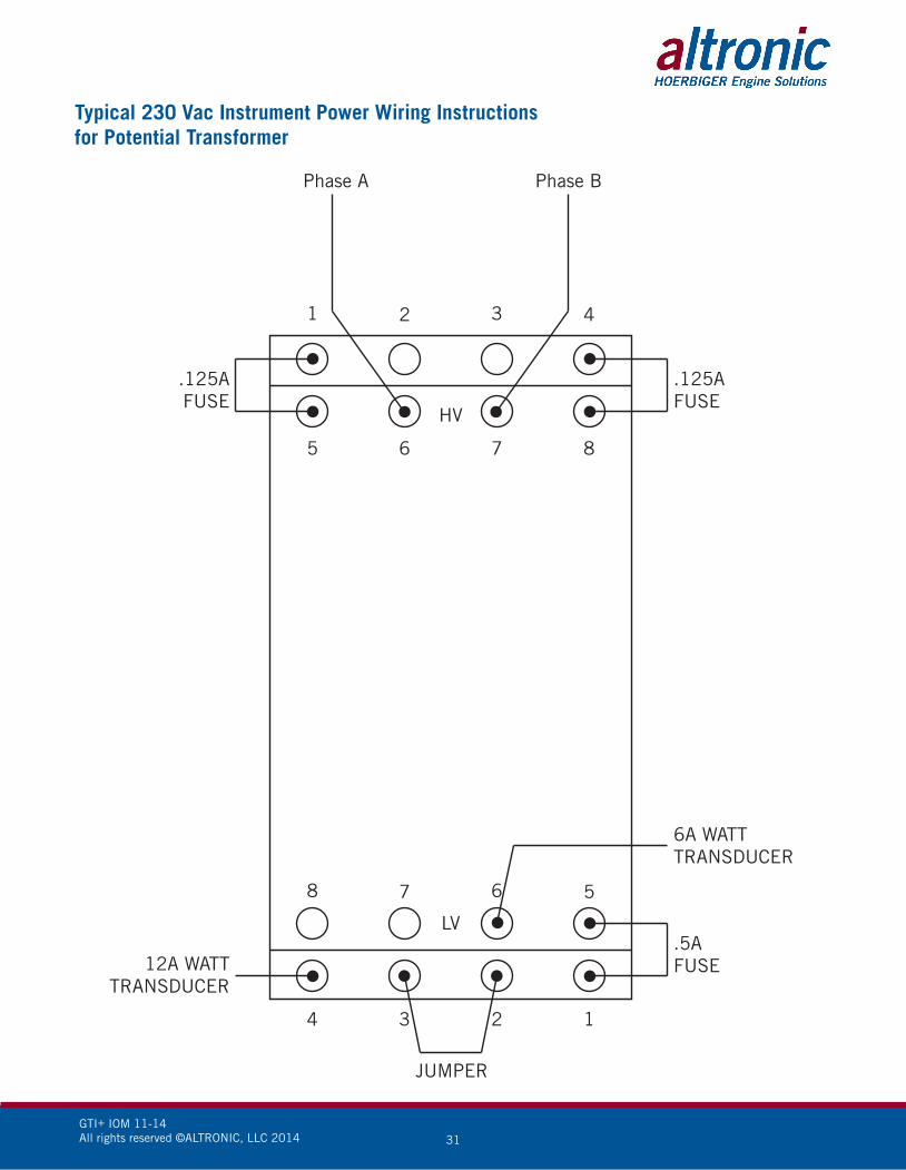
Typical 230 Vac Instrument Power Wiring Instructionsfor Potential Transformer
1 2 3 4
5 6 7 8
8 7 6 5
4 3 2 1
HV
LV
Phase A
JUMPER
Phase B
.125AFUSE
.125AFUSE
.5AFUSE12A WATT
TRANSDUCER
6A WATTTRANSDUCER
GTI+ IOM 11-14All rights reserved ©ALTRONIC, LLC 2014 32
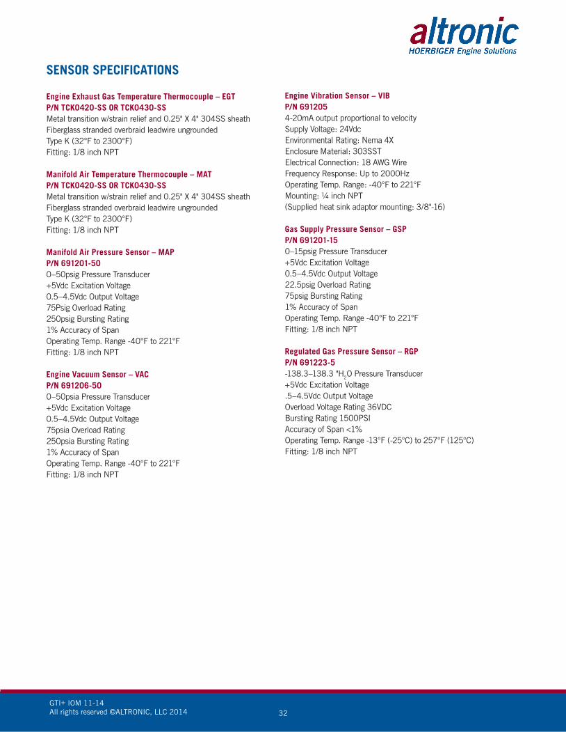
SENSOR SPECIFICATIONS
Engine Exhaust Gas Temperature Thermocouple – EGTP/N TCK0420-SS OR TCK0430-SS Metal transition w/strain relief and 0.25" X 4" 304SS sheathFiberglass stranded overbraid leadwire ungrounded Type K (32°F to 2300°F) Fitting: 1/8 inch NPT
Manifold Air Temperature Thermocouple – MAT P/N TCK0420-SS OR TCK0430-SS Metal transition w/strain relief and 0.25" X 4" 304SS sheathFiberglass stranded overbraid leadwire ungrounded Type K (32°F to 2300°F) Fitting: 1/8 inch NPT
Manifold Air Pressure Sensor – MAP P/N 691201-50 0–50psig Pressure Transducer+5Vdc Excitation Voltage 0.5–4.5Vdc Output Voltage 75Psig Overload Rating 250psig Bursting Rating 1% Accuracy of Span Operating Temp. Range -40°F to 221°F Fitting: 1/8 inch NPT
Engine Vacuum Sensor – VAC P/N 691206-50 0–50psia Pressure Transducer+5Vdc Excitation Voltage 0.5–4.5Vdc Output Voltage 75psia Overload Rating 250psia Bursting Rating 1% Accuracy of Span Operating Temp. Range -40°F to 221°F Fitting: 1/8 inch NPT
Engine Vibration Sensor – VIB P/N 691205 4-20mA output proportional to velocity Supply Voltage: 24Vdc Environmental Rating: Nema 4X Enclosure Material: 303SST Electrical Connection: 18 AWG Wire Frequency Response: Up to 2000Hz Operating Temp. Range: -40°F to 221°F Mounting: ¼ inch NPT (Supplied heat sink adaptor mounting: 3/8"-16)
Gas Supply Pressure Sensor – GSP P/N 691201-15 0–15psig Pressure Transducer+5Vdc Excitation Voltage 0.5–4.5Vdc Output Voltage 22.5psig Overload Rating 75psig Bursting Rating 1% Accuracy of Span Operating Temp. Range -40°F to 221°FFitting: 1/8 inch NPT
Regulated Gas Pressure Sensor – RGP P/N 691223-5-138.3–138.3 "H2O Pressure Transducer+5Vdc Excitation Voltage.5–4.5Vdc Output VoltageOverload Voltage Rating 36VDC Bursting Rating 1500PSIAccuracy of Span <1%Operating Temp. Range -13°F (-25°C) to 257°F (125°C)Fitting: 1/8 inch NPT

GTI+ IOM 11-14All rights reserved ©ALTRONIC, LLC 2014 33
GLOSSARY OF TERMS
AAAC Air to Air Aftercooling AGM-PV Air Gas Mixer-Power ValveAGV5-2L Altronic Gas Fuel Control Valve (Low Pressure)BMEP Brake Mean Effective Pressure BTU British Thermal Unit CAD Computer-Aided Design CH4 Methane Molecule CNC Computer Numeric Control (Machining) DGCS Dynamic Gas Control System DMV Dual Modular Valve Gas Solenoid EGT Engine Exhaust Gas Temperature EMI Electro Magnetic Interference GEG Gas Equivalent Gallon GEL Gas Equivalent Liter GPV Gas Power Valve GSP Gas Supply Pressure H2S Hydrogen Sulfide HC Hydrocarbons HP Horsepower ID Inside Diameter IPS Inches Per Second JIC Joint Industry Conference (Thread Specification) JWAC Jacket Water Aftercooling KCAL Kilocalories KPA Kilopascal KWE Kilowatt Electric LCD Liquid Crystal Display LED Light Emitting Diode LEL Lower Explosive Limit MAP Engine Manifold Air Pressure MAT Engine Manifold Air Temperature MBAR Millibar MJ Megajoule MPS Millimeters Per Second NBR Nitrile Rubber NPT National Pipe Thread Tapered OD Outside Diameter OEM Original Equipment (Engine) Manufacturer PMAX Peak Firing Pressure PSIA Pounds per Square Inch-Absolute PSIG Pounds per Square Inch-Gauge RFI Radio Frequency InterferenceRGP Regulated Gas Pressure Sensor ROP Regulator Output Pressure RPM Rotations Per Minute (Engine Speed) SCAC Separate Circuit Aftercooling SCF Standard Cubic Feet VAC Engine Vacuum VIB Engine Vibration WC Water Column ZG Zero Gas Pressure Regulator
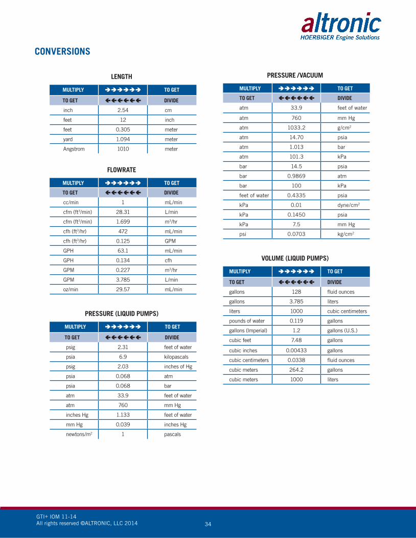
GTI+ IOM 11-14All rights reserved ©ALTRONIC, LLC 2014 34
PRESSURE /VACUUM
MULTIPLY TO GET
TO GET DIVIDE
atm 33.9 feet of water
atm 760 mm Hg
atm 1033.2 g/cm2
atm 14.70 psia
atm 1.013 bar
atm 101.3 kPa
bar 14.5 psia
bar 0.9869 atm
bar 100 kPa
feet of water 0.4335 psia
kPa 0.01 dyne/cm2
kPa 0.1450 psia
kPa 7.5 mm Hg
psi 0.0703 kg/cm2
VOLUME (LIQUID PUMPS)
MULTIPLY TO GET
TO GET DIVIDE
gallons 128 fluid ounces
gallons 3.785 liters
liters 1000 cubic centimeters
pounds of water 0.119 gallons
gallons (lmperial) 1.2 gallons (U.S.)
cubic feet 7.48 gallons
cubic inches 0.00433 gallons
cubic centimeters 0.0338 fluid ounces
cubic meters 264.2 gallons
cubic meters 1000 liters
CONVERSIONS
LENGTH
MULTIPLY TO GET
TO GET DIVIDE
inch 2.54 cm
feet 12 inch
feet 0.305 meter
yard 1.094 meter
Angstrom 1010 meter
FLOWRATE
MULTIPLY TO GET
TO GET DIVIDE
cc/min 1 mL/min
cfm (ft3/min) 28.31 L/min
cfm (ft3/min) 1.699 m3/hr
cfh (ft3/hr) 472 mL/min
cfh (ft3/hr) 0.125 GPM
GPH 63.1 mL/min
GPH 0.134 cfh
GPM 0.227 m3/hr
GPM 3.785 L/min
oz/min 29.57 mL/min
PRESSURE (LIQUID PUMPS)
MULTIPLY TO GET
TO GET DIVIDE
psig 2.31 feet of water
psia 6.9 kilopascals
psig 2.03 inches of Hg
psia 0.068 atm
psia 0.068 bar
atm 33.9 feet of water
atm 760 mm Hg
inches Hg 1.133 feet of water
mm Hg 0.039 inches Hg
newtons/m2 1 pascals

GTI+ IOM 11-14All rights reserved ©ALTRONIC, LLC 2014 35
MISCELLANEOUS
MULTIPLY TO GET
TO GET DIVIDE
hp 0.746 kW
hp 42.44 BTU/min
hp 396,000 lb in/min
hp 1.014 metric hp
watts 0.7376 lb ft/sec
watts 44.25 lb ft/min
lb-feet 0.1368 kg-m
oz-in 0.072 kg-cm
oz-in 70,600 dyne-cm
oz-in 0.00706 Nm
gauss 0.0001 tesla
VOLUME
MULTIPLY TO GET
TO GET DIVIDE
cubic cm (cc) 1 milliliters (mL)
ounces (fluid) 29.57 milliliters (mL)
cubic feet (ft3) 7.48 gallons
cubic feet (ft3) 0.0283 cubic meters (m3)
gallons 128 liters
gallons 3.785 ounces (fluid)
gallons 0.8333 imperial gallons
cubic meters (m3) 1000 liters
DENSITY CONVERSIONSSpecific Gravity x 1 = g/L
g/L x 8.345404 = lb/gal
lb/gal x 0.119826 = g/mL
TEMPERATURE°F = (1.8 x °C) + 32
°C = (°F – 32) x 0.555
°Kelvin = °C + 273.2