Embed Size (px)
Citation preview

INSTALLATION, OPERATION & MAINTENANCE INSTRUCTIONS
FOR LOW PROFILE-UNIT COOLERS AND DUAL FLOW
UNIT COOLER
SERIES “LPA” AIR DEFROST APPLICATION SERIES “LPE” ELECTRIC DEFROST APPLICATION SERIES “LPG” REVERSE CYCLE HOT GAS DEFROST SERIES “LPH” THREE PIPES HOT GAS DEFROST
SERIES “MVA” & “BVA” AIR DEFROST APPLICATION SERIES “MVE” & “BVE” ELECTRIC DEFROST APPLICATION SERIES “MVG” & “BVG” REVERSE CYCLE HOT GAS DEFROST SERIES “MVH” & “BVH” THREE PIPES HOT GAS DEFROST

2
WARNING: ELECTRICAL POWER MUST BE SWITCHED
OFF/DISCONNECTED BEFORE STARTING ANY SERVICE WORK ON
UNITS.
RECEIVING & INSPECTION
You have purchased one of the best units available today in the market with unique
features. Congratulations and thank you for using Kool-Air. Upon receipt of shipment,
please inspect the unit immediately and notify and file a claim with the transport if there
is any damage. Our shipment is thoroughly inspected before it is handed over to the
transport driver.
Location & Installation
The unit can be flush mounted against the ceiling or suspended from the ceiling
depending upon the height of the room. To ensure uniform air distribution throughout the
cooler a location should be chosen so that the air flow from the unit (both entering and
leaving) is unrestricted.
LP SERIE: To create air curtain effect, blow cold air towards the door of the cooler.
This unit draws air in from the coil and discharge cold air through the fan. The horizontal
throw of this unit is 20 to 30 feets. The unit must have at least an 8 inch space between
the coil and the wall for air movement.
MV & BV SERIE: These units draw air in from the fan and discharge cold air through
the coils. The horizontal air throw of these units is 12 to 18 feet for MV series and 10 to
15 feet for BV series. Unit spacing between two units should never exceed twice the air

3
throw. These units must have at least a 36 inch space between the coil and the wall for
proper air movement.
For “LPE”, “MVE” & “BVE” models, heaters are embedded into die-formed fin slots in
the face of the coil and therefore no space on the side is necessary for heater removal.
(the air throw shown is for optimum conditions, it can be affected by the room
height and the products loading.)
Wiring
All wiring must be done in accordance with national and local electrical codes. All
internal wiring of the unit is done at our factory and all wiring connections terminate at
the terminal block. The power supply must match with the name plate requirement. The
unit cabinet must be grounded. On applications where total heater amperage exceeds 40
amps the heaters must be wired through a separate contactor, which should be located
outside the cooler. Refer to the wiring diagram which is supplied with the unit for full
details.
Drain Line
LP SERIE: The ¾ inch MPT drain connection is factory mounted on the right side of the
unit when facing fans but can be easily moved to the left to accommodate field
requirements.

4
MV & BV SERIE: These units has a ¾ inch MPT drain connection
The drain line should be pitched sharply and exit the cooler/freezer on the shortest run as
possible. The drain line should be insulated and if the cooler temperature is below 32
degrees F drain line heaters (approx. 15 watts per foot of drain line) may be required. Do
not overlap the drain heaters. Provide drain trap outside the cooler/freezer in a warm area.
Refrigerant Connections / Piping
All refrigerant piping and connections must be installed in accordance with local and
national codes. Lines should be sized in accordance with the latest A.S.H.R.A.E.
Standards. Suction line trap(s) should be provided and suction line should be pitched
downward toward the compressor to prevent slugging and to ensure oil return to
compressor. Make sure the system is completely clean and dry. Evacuate the entire
system after it has been purged and leak tested, before charging it with refrigerant.
Expansion Valve
All units use externally equalized TX valves and are provided with an equalizer line
connection. All units liquid line/TX valve connections are sweat connections. Selection
of expansion valve is very important to get peak performance from the evaporator and to
have a balanced system. Check superheat reading and adjust it to obtain full evaporator
performance. Refer to expansion valve manufacturer’s catalogue for full details.

5
OPERATION
“LPA”, “MVA” & “BVA” models are for Air-Defrost applications, where cooler
temperature is +34 deg. F. or above. The coil can be defrosted by switching the
compressor off and just running the unit cooler fans. “LPE”, “LPG” and “LPH” models
are for freezer applications down to -20 deg. F. “BVE”, “MVE”, “BVG”, “MVG”,
“BVH” and “MVH”models are for freezer applications down to 26 deg. F. “LPE”,
“MVE” & “BVE” units are provided with high density stainless steel electric heaters,
factory set sealed fan delay/defrost termination thermostat. Adjust defrost timer
(maximum 45 minutes” to match the application and to ensure that the coil is completely
defrosted after each defrost cycle. Defrost thermostat must terminate defrost cycle and
fan delay thermostat must prevent moisture from being blown from the wet coil to the
freezer at the termination of the defrost cycle. Time initiated temperature terminated
defrost cycle is preferred to ensure clean coils at all times. Fan motor starts from the
defrost thermostat. All fan motors are permanently lubricated and thermally protected.
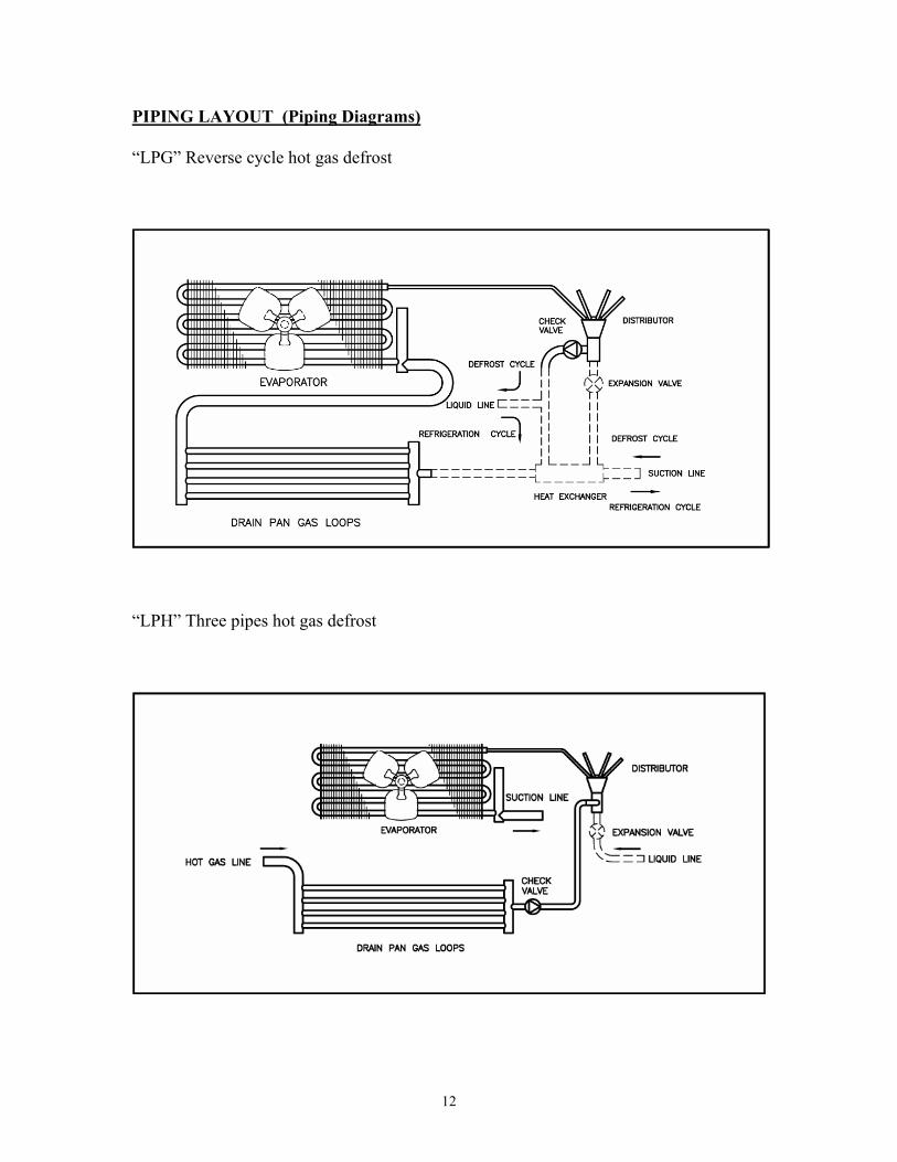
Fan motors may cycle due to thermal protection if the coil is blocked or iced up. “LPG”,
“LPH”, “MVG”, “MVH”, “BVG” and “BVH” units are defrosted by the hot gas from the
compressor discharge line. See piping diagram. A crankcase pressure regulating valve is
recommended on low temperature applications. Also a suction accumulator with boil out
coil or suction/liquid heat exchanger is recommended to avoid liquid slugging at
compressor.

6
MAINTENANCE
Periodically check the unit for any vibrations and dirt accumulation. Grease and dirt
should be removed from the fans, fan guards and drain pan. The drain line should be
checked and all foreign material removed. The finned surface may be cleaned using a
whisk or fin brush. These are relatively maintenance free units as the motors are
permanently lubricated and thermally protected.
REPLACEMENT PARTS
Use only manufacturer approved replacement parts. When ordering parts, please make
sure you have the complete model number, serial number and voltage information.

7
UNIT MOTOR FAN FAN GUARD
TERMINALBOARD
WIRE HARNESS DRAIN PAN
LPA-18-0380-1 M0010 F0010 F0204 E-0001 E-0030 1303D01 LPA-18-0520-1 M0010 F0010 F0204 E-0001 E-0030 1303D01 LPA-18-0610-1 M0010 F0010 F0204 E-0001 E-0030 1303D01 LPA-28-0860-1 M0010 F0010 F0204 E-0001 E-0030 1303D02 LPA-28-1000-1 M0010 F0010 F0204 E-0001 E-0030 1303D03 LPA-28-1160-1 M0010 F0010 F0204 E-0001 E-0030 1303D03 LPA-38-1570-1 M0010 F0010 F0204 E-0001 E-0030 0303D04 LPA-38-1860-1 M0010 F0010 F0204 E-0001 E-0030 0303D04 LPA-48-2140-1 M0010 F0010 F0204 E-0001 E-0030 1303D05 LPA-58-2630-1 M0010 F0010 F0204 E-0001 E-0030 1303D07 LPA-58-3130-1 M0010 F0010 F0204 E-0001 E-0030 1303D07 LPA-68-3500-1 M0010 F0010 F0204 E-0001 E-0030 1303D07
UNIT MOTOR FAN FAN GUARD
TERMINALBOARD
WIRE HARNESS DRAIN PAN HEATERS FAN
DELAY LPE-16-0480-2 M0015 F0010 F0204 E-0003 E-0030 1303D01 H-0010 E0004 LPE-16-0550-2 M0015 F0010 F0204 E-0003 E-0030 1303D01 H-0010 E0004 LPE-26-0780-2 M0015 F0010 F0204 E-0003 E-0030 1303D02 H-0015 E0004 LPE-26-0860-2 M0015 F0010 F0204 E-0003 E-0030 1303D03 H-0020 E0004 LPE-26-1080-2 M0015 F0010 F0204 E-0003 E-0030 1303D03 H-0020 E0004 LPE-36-1300-2 M0015 F0010 F0204 E-0003 E-0030 1303D04 H-0025 E0004 LPE-36-1660-2 M0015 F0010 F0204 E-0003 E-0030 1303D04 H-0025 E0004 LPE-46-2260-2 M0015 F0010 F0204 E-0003 E-0030 1303D05 H-0030 E0004 LPE-56-2890-2 M0015 F0010 F0204 E-0003 E-0030 1303D07 H-0035 E0004 LPE-66-3220-2 M0015 F0010 F0204 E-0003 E-0030 1303D07 H-0035 E0004
NOTE: THERE ARE 6 HEATERS PER UNIT 2 IN THE DRAIN PAN AND 4 IN THE COIL SLAB.
UNIT MOTOR FAN FAN GUARD
TERMINALBOARD
WIRE HARNESS DRAIN PAN
LP(G)(H)-16-0480-1 M0010 F0010 F0204 E-0001 E-0030 1303D01 LP(G)(H)-16-0550-1 M0010 F0010 F0204 E-0001 E-0030 1303D01 LP(G)(H)-26-0780-1 M0010 F0010 F0204 E-0001 E-0030 1303D02 LP(G)(H)-26-0860-1 M0010 F0010 F0204 E-0001 E-0030 1303D03 LP(G)(H)-26-1080-1 M0010 F0010 F0204 E-0001 E-0030 1303D03 LP(G)(H)-36-1300-1 M0010 F0010 F0204 E-0001 E-0030 1303D04 LP(G)(H)-36-1660-1 M0010 F0010 F0204 E-0001 E-0030 1303D04 LP(G)(H)-46-2260-1 M0010 F0010 F0204 E-0001 E-0030 1303D05 LP(G)(H)-56-2890-1 M0010 F0010 F0204 E-0001 E-0030 1303D07 LP(G)(H)-66-3220-1 M0010 F0010 F0204 E-0001 E-0030 1303D07
DRAIN FITTING KIT P0002

8
UNIT MOTOR FAN FAN GUARD
TERMINALBOARD
WIRE HARNESS DRAIN PAN
MVA-16-0600-1 M0010 F0012 F0204 E-0001 E-0030 1505D01 MVA-26-0850-1 M0010 F0012 F0204 E-0001 E-0030 1505D02 MVA-26-1200-1 M0010 F0012 F0204 E-0001 E-0030 1505D02 MVA-26-1350-1 M0010 F0012 F0204 E-0001 E-0030 1505D03 MVA-36-1800-1 M0010 F0012 F0204 E-0001 E-0030 1505D04 MVA-36-2000-1 M0010 F0012 F0204 E-0001 E-0030 1505D04 MVA-46-2800-1 M0010 F0012 F0204 E-0001 E-0030 1505D05 MVA-56-3600-1 M0010 F0012 F0204 E-0001 E-0030 1505D13 MVA-66-4500-1 M0010 F0012 F0204 E-0001 E-0030 1505D15
UNIT MOTOR FAN FAN GUARD
TERMINALBOARD
WIRE HARNESS DRAIN PAN HEATERS FAN
DELAY MVE-16-0600-2 M0015 F0012 F0204 E-0003 E-0030 1505D01 H-0010 E0004 MVE-26-0850-2 M0015 F0012 F0204 E-0003 E-0030 1505D02 H-0015 E0004 MVE-26-1200-2 M0015 F0012 F0204 E-0003 E-0030 1505D02 H-0015 E0004 MVE-26-1350-2 M0015 F0012 F0204 E-0003 E-0030 1505D03 H-0020 E0004 MVE-36-1800-2 M0015 F0012 F0204 E-0003 E-0030 1505D04 H-0025 E0004 MVE-36-2000-2 M0015 F0012 F0204 E-0003 E-0030 1505D04 H-0025 E0004 MVE-46-2800-2 M0015 F0012 F0204 E-0003 E-0030 1505D05 H-0030 E0004 MVE-56-3600-2 M0015 F0012 F0204 E-0003 E-0030 1505D13 H-0035 E0004 MVE-66-4500-2 M0015 F0012 F0204 E-0003 E-0030 1505D15 H-0035 E0004
NOTE: THERE ARE 6 HEATERS PER UNIT 2 IN THE DRAIN PAN AND 4 IN THE COIL SLAB.
UNIT MOTOR FAN FAN GUARD
TERMINALBOARD
WIRE HARNESS DRAIN PAN HEATERS FAN
DELAY MV(G)(H)-16-0600-1 M0010 F0012 F0204 E-0001 E-0030 1505D01 H-0010 E0004 MV(G)(H)-26-0850-1 M0010 F0012 F0204 E-0001 E-0030 1505D02 H-0015 E0004 MV(G)(H)-26-1200-1 M0010 F0012 F0204 E-0001 E-0030 1505D02 H-0015 E0004 MV(G)(H)-26-1350-1 M0010 F0012 F0204 E-0001 E-0030 1505D03 H-0020 E0004 MV(G)(H)-36-1800-1 M0010 F0012 F0204 E-0001 E-0030 1505D04 H-0025 E0004 MV(G)(H)-36-2000-1 M0010 F0012 F0204 E-0001 E-0030 1505D04 H-0025 E0004 MV(G)(H)-46-2800-1 M0010 F0012 F0204 E-0001 E-0030 1505D05 H-0030 E0004 MV(G)(H)-56-3600-1 M0010 F0012 F0204 E-0001 E-0030 1505D13 H-0035 E0004 MV(G)(H)-66-4500-1 M0010 F0012 F0204 E-0001 E-0030 1505D15 H-0035 E0004
NOTE: THERE ARE 2 HEATERS PER UNIT IN THE DRAIN PAN
DRAIN FITTING KIT P0002

9
UNIT MOTOR FAN FAN GUARD
TERMINALBOARD
WIRE HARNESS DRAIN PAN
BVA-16-0650-1 M0010 F0012 F0204 E-0001 E-0030 1505D21 BVA-16-0750-1 M0010 F0012 F0204 E-0001 E-0030 1505D21 BVA-26-0900-1 M0010 F0012 F0204 E-0001 E-0030 1505D09 BVA-26-1200-1 M0010 F0012 F0204 E-0001 E-0030 1505D09 BVA-26-1500-1 M0010 F0012 F0204 E-0001 E-0030 1505D09 BVA-26-1800-1 M0010 F0012 F0204 E-0001 E-0030 1505D11 BVA-36-2700-1 M0010 F0012 F0204 E-0001 E-0030 1505D10 BVA-46-3000-1 M0010 F0012 F0204 E-0001 E-0030 1505D12 BVA-56-3600-1 M0010 F0012 F0204 E-0001 E-0030 1505D13
UNIT MOTOR FAN FAN GUARD
TERMINALBOARD
WIRE HARNESS DRAIN PAN HEATERS FAN
DELAY BVE-16-0650-2 M0015 F0012 F0204 E-0003 E-0030 1505D21 H-0015 E0004 BVE-16-0750-2 M0015 F0012 F0204 E-0003 E-0030 1505D21 H-0015 E0004 BVE-26-0900-2 M0015 F0012 F0204 E-0003 E-0030 1505D09 H-0025 E0004 BVE-26-1200-2 M0015 F0012 F0204 E-0003 E-0030 1505D09 H-0025 E0004 BVE-26-1500-2 M0015 F0012 F0204 E-0003 E-0030 1505D09 H-0025 E0004 BVE-26-1800-2 M0015 F0012 F0204 E-0003 E-0030 1505D11 H-0030 E0004 BVE-36-2700-2 M0015 F0012 F0204 E-0003 E-0030 1505D10 H-0035 E0004 BVE-46-3000-2 M0015 F0012 F0204 E-0003 E-0030 1505D12 H-0035 E0004 BVE-56-3600-2 M0015 F0012 F0204 E-0003 E-0030 1505D13 H-0035 E0004
NOTE: THERE ARE 6 HEATERS PER UNIT 2 IN THE DRAIN PAN AND 4 IN THE COIL SLAB.
UNIT MOTOR FAN FAN GUARD
TERMINALBOARD
WIRE HARNESS DAIN PAN HEATERS FAN
DELAY BV(G) (H)-16-0650-1 M0010 F0012 F0204 E-0001 E-0030 1505D21 H-0015 E0004 BV(G) (H)-16-0750-1 M0010 F0012 F0204 E-0001 E-0030 1505D21 H-0015 E0004 BV(G) (H)-26-0900-1 M0010 F0012 F0204 E-0001 E-0030 1505D09 H-0025 E0004 BV(G) (H)-26-1200-1 M0010 F0012 F0204 E-0001 E-0030 1505D09 H-0025 E0004 BV(G) (H)-26-1500-1 M0010 F0012 F0204 E-0001 E-0030 1505D09 H-0025 E0004 BV(G) (H)-26-1800-1 M0010 F0012 F0204 E-0001 E-0030 1505D11 H-0030 E0004 BV(G) (H)-36-2700-1 M0010 F0012 F0204 E-0001 E-0030 1505D10 H-0035 E0004 BV(G) (H)-46-3000-1 M0010 F0012 F0204 E-0001 E-0030 1505D12 H-0035 E0004 BV(G) (H)-56-3600-1 M0010 F0012 F0204 E-0001 E-0030 1505D13 H-0035 E0004
NOTE: THERE ARE 2 HEATERS PER UNIT IN THE DRAIN PAN
DRAIN FITTING KIT P0002

10
ELECTRICALS (Wiring Diagrams)
“LPA, MVA & BVA” Air Defrost
“LPE, MVE & BVE” Electric Defrost

11
“LP (G, H)” Reverse cycle hot gas defrost & 3 pipes defrost
“MV (G, H)” & “BV (G, H)” Reverse cycle hot gas defrost & 3 pipes defrost
12
PIPING LAYOUT (Piping Diagrams)
“LPG” Reverse cycle hot gas defrost
“LPH” Three pipes hot gas defrost

13
PIPING LAYOUT (Piping Diagrams)
“MVG“ & “BVG” Reverse cycle hot gas defrost
“MVH” & “BVH” Three pipes hot gas defrost

14
HEAD OFFICE: ONTARIO SALES OFFICE: REFRIGERATION KOOL-AIR INC. REFRIGERATION KOOL-AIR INC. 100 Conrad Gosselin 237 Valleymede Drive Iberville, Québec Canada Richmond Hill, Ontario Canada J2X 5L6 L4B 2A3 Tel: (450) 346-5007 Tel: (905) 771-8972 Toll free: (1-866-346-5007 Fax: (905) 771-8908 Fax: (450) 346-7631 Due to Kool-Air policies to continuously improve the quality of its products, specifications are subject to change without notice.