Embed Size (px)
Citation preview

481324 Curtain Fire Dampers 1®
Document number 481324 CURTAIN FIRE DAMPERS
DFD, DFD-150X, FD, FD-150X, SSDFD, SSFD, AND KFD Series 11⁄2 and 3 Hour Curtain Fire Dampers
Vertical and Horizontal Mount
Installation, Operation and Maintenance ManualPlease read and save these instructions for future reference. Read carefully before attempting to assemble, install, operate or maintain the product described. Protect yourself and others by observing all safety information. Failure to comply with instructions could result in voiding of the product warranty and may result in personal injury and/or property damage.
Table of ContentsGeneral Information ......................................2
Pre-Installation Guidelines ............................2
Installation ................................................3-12
• Preparation of Openings ........................3
• Clearances Required Between Damper Sleeves & Wall/Floor Openings .............4
• Installing Multiple Section Assemblies ...5
• Maximum Assembly Tables ....................5
• Sleeve Length Requirements ..................6
• Securing the Damper/Sleeve Assembly to Wall/Floor Openings ......7-9
• Duct to Sleeve Connection ..............10-11
• No Connecting Duct or Transfer Opening ..................................12
Maintenance ...............................................12
Troubleshooting ..........................................12
These instructions apply to 11⁄2 and 3 hour rated fire dampers mounted (blades must be horizontal) in: 1) masonry, block, or stud walls and 2) concrete floors. Specific requirements in these instructions are mandatory. Dampers must be installed in accordance with these instructions to meet the requirements of UL 555.
Note: Fire dampers are manufactured and labeled for either vertical or horizontal installation. The dampers must be installed in accordance with labeling.
Receiving and HandlingUpon receiving dampers, check for both obvious and hidden damage. If damage is found, record all necessary information on the bill of lading and file a claim with the final carrier. Check to be sure that all parts of the shipment, including accessories, are accounted for.
Dampers must be kept dry and clean. Indoor storage and protection from dirt, dust and the weather is highly recommended. Do not store at temperatures in excess of 100°F (38°C).
Safety WarningImproper installation, adjustment, alteration, service or maintenance can cause property damage, injury or death. Read the installation, operating, and maintenance instructions thoroughly before installing or servicing this equipment.
This manual is the property of the owner and is required for future maintenance. Please leave it with the owner when the jobs is complete.
®

481324 Curtain Fire Dampers 2®
General Information
Installation SupplementsRefer to the appropriate Greenheck installation supplements for special requirements:
• Closed Indicator Switch • Concrete Floor with Steel Deck • Drive Slip Breakaway Connection • Field Installed Sleeve • Fire Resistant Ventilated Duct Assembly • Firestop Material • Fusible Link Replacement • Grille Installation • Metal Stud in Shaftwall Partition • Non-Concrete Horizontal Mount • Quick Connect Breakaway Connection • Sealant Supplement • Single Side Retaining Angle • Single 3-Sided Retaining Angle Supplement • Sleeve Extension • Support Mullions
Installation supplements available at www.greenheck.com.
“UL CLASSIFIED (see complete marking on product)”“UL CLASSIFIED to Canadian safety standards (see complete marking on product)” Standard 555 (Listing #R13317)
The following items will aid in completing the damper installation in a timely and effective manner.
1) Check the schedules for proper damper locations within the building. Visually inspect the damper for damage and verify that the fusible link is in place and has not activated. Never install a fire damper without the proper UL approved fusible link in place. Visually inspect the link to verify its not damaged. Replace link as necessary.
2) Lift or handle damper using sleeve or frame. Do not lift damper using blades.
3) Dampers have a label indicating the required mounting orientation. When the mounting orientation is horizontal, the 'K side' must be up. Care must be taken to ensure that the indicated orientation is adhered to.
4) Damper must be installed into duct or opening square and free of twist or other misalignment.
5) Damper must be kept clean and protected from dirt, dust and other foreign materials prior to and after installation. Examples of such foreign materials include but are not limited to:
a) Mortar dust b) Drywall dust c) Firesafing materials d) Wall texture e) Paint overspray
6) Damper should be sufficiently covered as to prevent overspray if wall texturing or spray painting will be performed within 5 feet of the damper.
7) Caulking is not necessary, nor is it allowed, between the damper sleeve and the wall or floor opening (annular space). However, caulking may be applied to the retaining angles.
8) ACCESS: Suitable access (such that the fusible link may be removed and the damper's blade stack may be reset, etc.) must be provided for damper inspection and servicing. Where it is not possible to achieve sufficient size access, it will be necessary to install a removable section of duct. (Refer to NFPA 90A).
9) The Code Authority Having Jurisdiction (AHJ) must evaluate and provide approval of final installation where variations to these instructions are necessary.
Pre-Installation Guidelines
“K” side
W*
H*
Vertical Mount
Horizontal Mount
Stainless SteelClosure Spring
3 11/16 in.(94mm)
Fusible Link (replaceable)

481324 Curtain Fire Dampers 3®
Preparation of Openings
• Frame wall openings as shown below (see Figure 1 & 2).
• Gypsum wall board must be fastened 12 in. (305mm) on center to all stud and runner flanges surrounding opening.
• Prepare opening between studs and sleeve assembly as shown below (see Figure 3 & 4).
• All construction and fasteners must meet the requirements of the appropriate wall design (See UL Fire Resistance Directory) and/or local codes.
Figure 1
12 in.
24 in. o.c.Maximum
Floor Runner
Ceiling Runner24 in. o.c.Maximum
(metal studs)
24 in. o.c.Maximum
(metal studs)
16 in. o.c.Maximum
(wood studs)
16 in. o.c.Maximum
(wood studs)
2 in. (51mm)
2 in. (51mm)
2 Panhead Screws
Second set of studs are not required on openings 36 in. x 36 in. (914mm x 914mm) or smaller.
Figure 2
Second set of studs are not required on openings36 in. x 36 in. (914mm x 914mm) or smaller.
Metal stud only
Second set of studs are not required on openings36 in. x 36 in. (914mm x 914mm) or smaller.
Metal stud only
Metal Stud Construction
Wooden Stud Construction
In wood stud construction,gypsum wallboard must coverall wood stud surfaces.
Gypsum Wallboard
Stud or Runner
RetainingAngle
1 in. Min.
DamperSleeve
In metal stud construction,exposed steel surfaces neednot be covered with gypsumwallboard.
Gypsum Wallboard
Stud or Runner
RetainingAngle
1 in. Min.
DamperSleeve
Figure 3 (2 sided angle installation shown)
Metal Stud Construction
Wooden Stud Construction
In wood stud construction,gypsum wallboard must coverall wood stud surfaces.
Gypsum Wallboard
Stud or Runner
RetainingAngle
1 in. Min.
DamperSleeve
In metal stud construction,exposed steel surfaces neednot be covered with gypsumwallboard.
Gypsum Wallboard
Stud or Runner
RetainingAngle
1 in. Min.
DamperSleeve
Figure 4 (2 sided angle installation shown)

481324 Curtain Fire Dampers 4®
Clearances Required Between Damper Sleeves & Wall/Floor Openings
Two-sided Angle InstallationTwo sided angle installations require clearances for thermal expansion between the damper sleeve and the wall/floor opening. The minimum required clearances are:
• For galvanized steel fire dampers and sleeves: 1⁄8 in. per foot (3mm per .3 m) of damper width and 1⁄8 in. per foot (3mm per .3 m) height with a minimum clearance of 1⁄4 in. (6mm), maximum of 11⁄2 in. (38mm).
• For stainless steel fire/smoke dampers and stainless steel or galvanized sleeves: 3⁄16 in. per foot (5mm per .3 m) of damper width and height with a minimum clearance of 1/4 in. (6mm), maximum of 2 in. (51mm).
These are total clearances (ignoring fastener heads) and do not need to be equally spaced around the damper.
Although the minimum requirements are listed above, for ease of installation the following are the recommended clearances for galvanized dampers:
• Width/Height of 48 in. (1219 mm) or less - 1⁄2 in. (13mm) clearance
• Width/Height between 48.01 in. (1220 mm) and 96 in. (2438 mm): 1 in. (25mm) clearance
• Width/Height greater than 96 in. (2438 mm): 11⁄2 in. (38 mm) clearance
Example: A 12 in. x 12 in. (305mm x 305mm) will
require a minimum clearance of 1/4 in. (6mm) width and 1/4 in. (6mm) on height
A 48 in. x 12 in. (1219mm x 305mm) damper will required a minimum clearance of 1⁄2 in. (13mm) on width and 1/4 in. (6mm) on height.
Single Side Angle Installation
On vertical mount single side angle installations there are no minimum clearance requirements between the wall opening and the damper sleeve. However, to facilitate installation, clearances between the wall opening and the damper sleeve are recommended.
On horizontal mount single side angle installations a minimum clearance is required between the outside of the damper sleeve and the floor opening of 1⁄8 in. per foot (3mm per .3m) of damper width and 1⁄8 in. per foot (3mm per .3m) height with a minimum clearance of 1/4 in. (6mm).
481324 Curtain Fire Dampers 5®
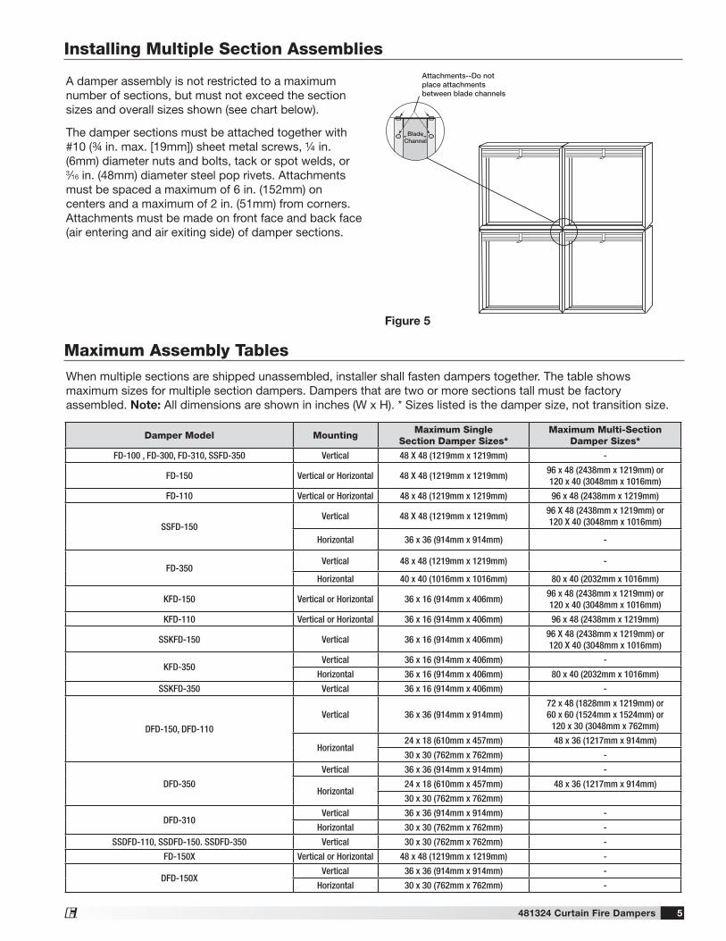
Maximum Assembly TablesWhen multiple sections are shipped unassembled, installer shall fasten dampers together. The table shows maximum sizes for multiple section dampers. Dampers that are two or more sections tall must be factory assembled. Note: All dimensions are shown in inches (W x H). * Sizes listed is the damper size, not transition size.
Damper Model MountingMaximum Single
Section Damper Sizes*Maximum Multi-Section
Damper Sizes*
FD-100 , FD-300, FD-310, SSFD-350 Vertical 48 X 48 (1219mm x 1219mm) -
FD-150 Vertical or Horizontal 48 X 48 (1219mm x 1219mm)96 x 48 (2438mm x 1219mm) or120 x 40 (3048mm x 1016mm)
FD-110 Vertical or Horizontal 48 x 48 (1219mm x 1219mm) 96 x 48 (2438mm x 1219mm)
SSFD-150Vertical 48 X 48 (1219mm x 1219mm)
96 X 48 (2438mm x 1219mm) or 120 X 40 (3048mm x 1016mm)
Horizontal 36 x 36 (914mm x 914mm) -
FD-350Vertical 48 x 48 (1219mm x 1219mm) -
Horizontal 40 x 40 (1016mm x 1016mm) 80 x 40 (2032mm x 1016mm)
KFD-150 Vertical or Horizontal 36 x 16 (914mm x 406mm)96 x 48 (2438mm x 1219mm) or120 x 40 (3048mm x 1016mm)
KFD-110 Vertical or Horizontal 36 x 16 (914mm x 406mm) 96 x 48 (2438mm x 1219mm)
SSKFD-150 Vertical 36 x 16 (914mm x 406mm)96 X 48 (2438mm x 1219mm) or 120 X 40 (3048mm x 1016mm)
KFD-350Vertical 36 x 16 (914mm x 406mm) -
Horizontal 36 x 16 (914mm x 406mm) 80 x 40 (2032mm x 1016mm)
SSKFD-350 Vertical 36 x 16 (914mm x 406mm) -
DFD-150, DFD-110
Vertical 36 x 36 (914mm x 914mm)72 x 48 (1828mm x 1219mm) or60 x 60 (1524mm x 1524mm) or
120 x 30 (3048mm x 762mm)
Horizontal24 x 18 (610mm x 457mm) 48 x 36 (1217mm x 914mm)
30 x 30 (762mm x 762mm) -
DFD-350
Vertical 36 x 36 (914mm x 914mm) -
Horizontal24 x 18 (610mm x 457mm) 48 x 36 (1217mm x 914mm)
30 x 30 (762mm x 762mm)
DFD-310Vertical 36 x 36 (914mm x 914mm) -
Horizontal 30 x 30 (762mm x 762mm) -
SSDFD-110, SSDFD-150. SSDFD-350 Vertical 30 x 30 (762mm x 762mm) -
FD-150X Vertical or Horizontal 48 x 48 (1219mm x 1219mm) -
DFD-150XVertical 36 x 36 (914mm x 914mm) -
Horizontal 30 x 30 (762mm x 762mm) -
Installing Multiple Section Assemblies
A damper assembly is not restricted to a maximum number of sections, but must not exceed the section sizes and overall sizes shown (see chart below).
The damper sections must be attached together with #10 (3/4 in. max. [19mm]) sheet metal screws, 1/4 in. (6mm) diameter nuts and bolts, tack or spot welds, or 3⁄16 in. (48mm) diameter steel pop rivets. Attachments must be spaced a maximum of 6 in. (152mm) on centers and a maximum of 2 in. (51mm) from corners. Attachments must be made on front face and back face (air entering and air exiting side) of damper sections.
Attachments--Do not place attachments between blade channels
Blade Channel
Figure 5
481324 Curtain Fire Dampers 6®
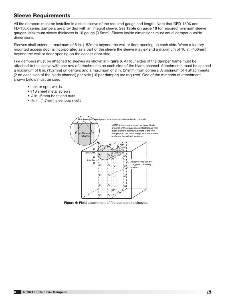
Sleeve Requirements
Attachments--Do not place attachments between blade channels
Blade Channel
2 in. Max.
6 in. Max.Attachments can be staggered or evenlyspaced.
NOTE: Attachments must not enter blade channel or they may cause interference with blade closure. Narrow Line and Ultra Thin dampers do not have flange for attachments and must be welded to sleeve.
Figure 6: Field attachment of fire dampers to sleeves.
All fire dampers must be installed in a steel sleeve of the required gauge and length. Note that DFD-150X and FD-150X series dampers are provided with an integral sleeve. See Table on page 10 for required minimum sleeve gauges. Maximum sleeve thickness is 10 gauge (3.5mm). Sleeve inside dimensions must equal damper outside dimensions.
Sleeves shall extend a maximum of 6 in. (152mm) beyond the wall or floor opening on each side. When a factory mounted access door is incorporated as a part of the sleeve the sleeve may extend a maximum of 16 in. (406mm) beyond the wall or floor opening on the access door side.
Fire dampers must be attached to sleeves as shown in Figure 6. All four sides of the damper frame must be attached to the sleeve with one row of attachments on each side of the blade channel. Attachments must be spaced a maximum of 6 in. (152mm) on centers and a maximum of 2 in. (51mm) from corners. A minimum of 4 attachments (2 on each side of the blade channel) per side (16 per damper) are required. One of the methods of attachment shown below must be used:
• tack or spot welds • #10 sheet metal screws • 1⁄4 in. (6mm) bolts and nuts • 3⁄16 in. (4.7mm) steel pop rivets

481324 Curtain Fire Dampers 7®
The fire damper must be installed such that the centerline of the blades are mounted in the plane of the wall or floor.
All fire dampers may utilize the two sided angle installation method described below. 11⁄2 hour rated fire dampers may use the single sided angle installation method up to the following maximum sizes:
• Vertical mount: 80 in. W x 50. in. H (2032mm W x 1270mm H), 50 in. W x 80 in. H (1270mm W x 2032mm H), or 40 in. W x 100 in. H (1016mm W x 2540mm).
• Horizontal mount: 144 in. W x 96 in. H (3658mm W x 2438mm H)
• Retaining Angle Gauge: Retaining angles for 11⁄2 hour rated dampers with a width and height 48 in. (1219mm) or less must be a minimum of 20 ga. (1mm). Retaining angles for all 3 hour rated dampers and all dampers with a width or height greater than 48 in. (1219mm) must be a minimum of 16 gauge (1.5mm).
• Retaining Angle Size: The leg of the retaining angle on the damper sleeve shall be a minimum of 11/4 in. (32mm). The leg of the retaining angle on the wall/floor shall be long enough to cover the annular space and overlap the wall/floor by a minimum of 1 in. (25mm).
• Retaining Angle Attachment to Sleeve: Retaining angles must be attached to the damper using one or more of the following methods of attachment (refer to label on outside of sleeve for ‘No Screw’ area):
- Tack or spot welds - #10 (3⁄4 in. [19mm] max.) sheet metal screws - 1⁄4 in. (6mm) bolts and nuts - 3⁄16 in. (5mm) steel pop rivets
A minimum of two connections per side, top, and bottom, 12 in. (305mm) O.C. maximum for openings of 48 in. W x 36 in. H (1219mm x 914mm) and less. Dampers greater than 48 in. wide (1219mm) or 36 in. high (914mm) require the connections to be no more than 6 in. (152mm) O.C.
The angles must be attached to all 4 sides of the sleeve. Ensure that fasteners do not interfere with the operation of the damper. The angles need not be attached to each other at the corners.
• Retaining Angle Attachment to Wall/Floor:
Two sided Angle Method: For two sided angle installations the retaining angles shall not be attached to the wall/floor (see Figure 7).
Single Sided Angle Method: For single side installations the retaining angles must be attached to the wall/floor (see Figures 8-11). For metal stud partitions only, the single-side mounting angle may be directly attached to the metal stud prior to the installation of the drywall.
• Retaining angles must be attached to the partition using one of the methods shown below:
- Drywall screws of a length such that the screw engages the steel stud/track by 1⁄2 in. (13mm) (steel framing).
- Drywall screws of a length such that the screw engages the wood stud by 13/4 in. (44mm) (wood framing).
- Steel anchors or self tapping concrete screws penetrating masonry or block 11/4 in. (31mm).
• A minimum of two connections per side are required. Additional connections made at a maximum of 12 in. (305mm) O.C. maximum for openings of 48 in. W x 36 in. H (1219mm x 914mm) and less. Dampers greater than 48 in. wide (1219mm) or 36 in. high (914mm) require the connections to be no more than 6 in. (152mm) O.C.
Securing the Damper/Sleeve Assembly to Wall/Floor Openings
2 in. Max.
6 in. Max.
Sleeve
RetainingAngle
Damper
Duct
Min. 1 in.Overlap*
Wall orFloor
RetainingAngle
*only applicable for damper sizes above 36 in. x 36 in.
6 in. Max.
2 in. Max.
Figure 7: Two Sided Angle Installation

481324 Curtain Fire Dampers 8®
Securing the Damper/Sleeve Assembly to Wall/Floor Openings cont.......
Damper Sleeve
Angle Fastener
2 1/2 in. min.Stud or Runner
Two layers of 1/2 in. UL Classified Gypsum Wallboard for 2 hour rated walls. One layer for 1 hour rated walls (see UL Rated Wall Design for Additional Details).
Figure 8: Single Side Angle With Steel Stud Wall - Angle Over Wallboard
Damper Sleeve
2 1/2 in. min.Metal Studor Runner
Two layers of 1/2 in. UL Classified Gypsum Wallboard for 2 hour rated walls. One layer for 1 hour rated walls (see UL Rated Wall Design for Additional Details).
Figure 10: Single Side Angle With Steel Stud Wall - Angle Under Wallboard
2 1/2 in. Min.Stud or Runner
DamperSleeve
Angle Fastener
Two layers of 1/2 in. UL Classified Gypsum Wallboard for 2 hour rated walls. One layer for 1 hour rated walls (see UL Rated Wall Design for Additional Details).
Figure 9: Single Side Angle With Wood Stud Wall
Masonry orConcreteWall
DamperSleeve
Angle Fastener
Masonry orConcrete Floor
DamperSleeve
Angle Fastener
Top Side
Figure 11: Single Side Angle With Masonry or Concrete Wall and Floor
Grille Installations (Dampers up to 36 in. x 36 in. [914mm x 914mm])Retaining angles used in conjunction with grille installations must be a minimum of 5⁄8 in. x 1 in. (15mm x 25mm) 16 gauge (1.5mm) steel. Space screws a maximum of 6 in. (152mm) on center and a maximum of 2 in. (51mm) from the corners (minimum of 2 screws per side). See Figure 12 and Figure 13.
Note: Screws used to attach grille are allowed to penetrate reversed angle leg.
DamperSleeve
Angle Fastener
Grille (suppliedby others)
#10 sheet metal screwsspaced 6 in. on centerand a maximum of 2 in.from the corners(minimum of 2 screws perside). Screw into studs soas to avoid spaceconflicts with the grille
2 1/2 in. Min.Stud or Runner
Retaining Angle/Flange
Two layers of 1/2 in. UL Classified Gypsum Wallboard for 2 hour rated walls. One layer for 1 hour rated walls (see UL Rated Wall Design for Additional Details).
Figure 13: Metal Stud - Grille
Two layers of 1/2 in. UL Classified Gypsum Wallboard for 2 hour rated walls. One layer for 1 hour rated walls (see UL Rated Wall Design for Additional Details).
Grille (supplied by others)Retaining Angle
Angle Fastener
Damper Sleeve
#10 sheet metal screws, 2 1/2 inches long, spaced 6 in. on center and amaximum of 2 in. from the corners (minimum of 2 screws per side). Screw into studs so as to avoid space conflicts with the grille.
2 1/2 in. minimumStud or Runner
Figure 12: Wood Stud - Grille

481324 Curtain Fire Dampers 9®
Securing the Damper/Sleeve Assembly to Wall/Floor Openings cont.......
1/4 in. minimumtotal clearance
Wall or Floor
Maximum 6 in.
Maximum 6 in.
Duct
Duct
Duct
Damper
Damper
Damper
Wall or Floor
Wall or Floor
Retaining Angles
Type A
Type B
On types R, CO & CR factoryfurnished duct collarqualifies as breakaway connection.
Type C, CO, CR, & R
Factory or Field installed Sleeve
Wall or Floor
Retaining Angles
Sleeve
Duct
“K” side
Damper
Max. 6 in.
Max. 6 in.
Type BFactory Sleeve
Type B2
Type B2
Wall or floor
Damper
Sleeve
Wall or floor
Damper
Sleeve
Factory Sleeve
Damper
1/4 in. minimumtotal clearance(See Section 1)
Maximum 6 in.
Maximum 6 in.
Wall or floor
Wall or floor
Wall or floor
Damper
Damper
Duct
Duct
Duct
Retaining Angles(See Section 4)
Sleeve(See Sleeve Requirements)
Sleeve
Sleeve
On types R & CR factoryfurnished duct collarqualifies as breakawayconnection (See Connecting Ducts to Fire Damper Sleeve)
1 in. min. overlapFour sides
Mounting Angles(See Para. 4)
1/4 in. minimum total clearance(See Para. 1)
Retaining angle leg shall not exceed 7 in. (178mm)
Type A
Type B
Type C, CO, CR & R
Field Installed Sleeve
Damper
1/4 in. minimumtotal clearance(See Section 1)
Maximum 6 in.
Maximum 6 in.
Wall or floor
Wall or floor
Wall or floor
Damper
Damper
Duct
Duct
Duct
Retaining Angles(See Section 4)
Sleeve(See Sleeve Requirements)
Sleeve
Sleeve
On types R & CR factoryfurnished duct collarqualifies as breakawayconnection (See Connecting Ducts to Fire Damper Sleeve)
1 in. min. overlapFour sides
Mounting Angles(See Para. 4)
1/4 in. minimum total clearance(See Para. 1)
Retaining angle leg shall not exceed 7 in. (178mm)
Type A
Type B
Type C, CO, CR & RField installed SleeveFactory Sleeve
1/4 in. minimumtotal clearance
Wall or Floor
Maximum 6 in.
Maximum 6 in.
Duct
Duct
Duct
Damper
Damper
Damper
Wall or Floor
Wall or Floor
Retaining Angles
Type A
Type B
On types R, CO & CR factoryfurnished duct collarqualifies as breakaway connection.
Type C, CO, CR, & R
Figure 14: Damper/Sleeves with Transition

481324 Curtain Fire Dampers 10®
Duct to Sleeve Connection
Sleeve Gauge and Connection Type Requirements
Sleeve Gauge Duct Dimension
Type of Duct to Sleeve
Connection Permitted
14 ga. (0.075 in.) - 10 ga. (0.138
in.)[2mm - 3.5mm]
All duct sizesRigid or
Breakaway
16 ga. (0.060 in.)[1.5mm]
36 in. (914mm) max. width24 in. (610mm) max.
height24 in. (610mm) diameter
Rigid or Breakaway
16 ga. (0.060 in.)[1.5mm]
All duct sizes
Breakaway only
18 ga. (0.048 in.)[1.2mm]
85 in. (2159mm) wide and over
20 ga. (0.036 in.)[0.9mm]
55 in. - 84 in. wide(1397mm - 2134mm)
22 ga. (.030 in.)[0.76mm]
31 in. - 54 in. wide(787mm - 1372mm)
24 ga. (0.024)[0.6mm]
13 in. - 30 in. wide(330mm - 762mm)
26 ga. (0.018 in.)[0.46mm]
12 in. wide and under(305mm)
See Breakaway Connection section for additional information.UL Standard 555 requires all ducts to terminate at fire damper sleeves.
Approved Breakaway ConnectionsAll breakaway connections described below may utilize the following duct sealants: PA2084T duct sealant adhesive manufactured by Precision, DP1010 water base duct sealant manufactured by Design Polymetrics, Grey Pookie, Ductmate PROseal®, or CL Ward S Seal in accordance with SMACNA recommendations.
Transverse JointsThe transverse joints shown below are approved as breakaway connections.
• A maximum of two #10 (19mm) sheet metal screws on each side and on the bottom may be used. The screws should be located in the center of the slip pocket and penetrate both sides of the slip pocket.
• Dampers up to 20 inches (508mm) high may use transverse joints on the top and bottom and Drive Slip joints (see Figure 16) on the sides.
Plain “S” Slip Hemmed “S” Slip Double “S” Slip
Inside Slip Joint Standing “S” Standing “S” (Alt.)
Standing “S” (Alt.) Standing “S” Standing “S” (Bar Reinforced) (Angle Reinforced)
Figure 15 - Transverse Joints
Drive Slip Joint
Figure 16
The size of the damper/duct determines the required sleeve gauge and the required duct to sleeve connection (see table to the right). The sleeve thickness must also not be less than the gauge of the connecting duct. Any duct connection other than the breakaway connections described below are considered rigid.
481324 Curtain Fire Dampers 11®
Duct to Sleeve Connection cont....
DuctSleeve
6 in.
Std. ClipLength
CLDuct
60 in. Duct4 Req’d.
48 in. Duct3 Req’d.
36 in. Duct3 Req’d.
24 in. Duct2 Req’d.
18 in. Duct &Smaller1 Req’d.
Clip Spacing
Typical TDC/TDF joint
6 in. 6 in.9 in.
7 in.7 in.
5 in. 5 in.
5 in.5 in.
Figure 20
Duct EndFlange
Corner Piece
3/8 in. bolt (optional)
Figure 21
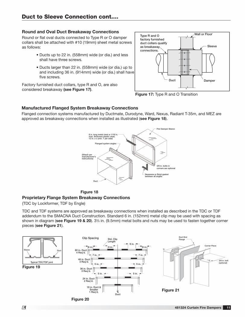
Proprietary Flange System Breakaway Connections(TDC by Lockformer, TDF by Engle)
TDC and TDF systems are approved as breakaway connections when installed as described in the TDC or TDF addendum to the SMACNA Duct Construction. Standard 6 in. (152mm) metal clip may be used with spacing as shown in diagram (see Figure 19 & 20). 33⁄8 in. (9.5mm) metal bolts and nuts may be used to fasten together corner pieces (see Figure 21).
DuctSleeve
6 in.
Std. ClipLength
CLDuct
60 in. Duct4 Req’d.
48 in. Duct3 Req’d.
36 in. Duct3 Req’d.
24 in. Duct2 Req’d.
18 in. Duct &Smaller1 Req’d.
Clip Spacing
Typical TDC/TDF joint
6 in. 6 in.9 in.
7 in.7 in.
5 in. 5 in.
5 in.5 in.
Figure 19
Round and Oval Duct Breakaway ConnectionsRound or flat oval ducts connected to Type R or O damper collars shall be attached with #10 (19mm) sheet metal screws as follows:
• Ducts up to 22 in. (558mm) wide (or dia.) and less shall have three screws.
• Ducts larger than 22 in. (558mm) wide (or dia.) up to and including 36 in. (914mm) wide (or dia.) shall have five screws.
Factory furnished duct collars, type R and O, are also considered breakaway (see Figure 17).
Fire Damper Sleeve
Neoprene or Butyl gasketbetween all angles
Flanged system angles
(Attach permanufacturer'sinstructions)
Duct
3/8 in. bolts incorners are optional
6 in. long metal cleat or 1/16 in.max. thickness plastic cleat;12 in. c-c (min. 1 per side)
Figure 18
Wall or Floor
Sleeve
Duct Damper
Type B
Wall or Floor
Sleeve
Duct Damper
Type R, O
Type R and Ofactory furnishedduct collars qualifyas breakawayconnections.
Figure 17: Type R and O Transition
Manufactured Flanged System Breakaway ConnectionsFlanged connection systems manufactured by Ductmate, Durodyne, Ward, Nexus, Radiant T-35m, and MEZ are approved as breakaway connections when installed as illustrated (see Figure 18).

Damper MaintenanceDampers do not typically require maintenance as long as they are kept dry and clean. If cleaning is necessary, use mild detergents or solvents. If lubrication is desired for components such as axle bearings, jackshaft bearings and jamb seals, do not use oil-based lubricants or any other lubricants that attract contaminants such as dust.
Damper TroubleshootingThe following is a possible cause and correction list for common concerns with the dampers.
Symptom Possible Cause Corrective Action
Damper does not fully open and/or close
Frame is 'racked' causing blades to bind on jamb seals
Adjust frame such that it is square and plumb
Screws in damper linkage Damper installed too far into wall. Move out to line as designated on damper label
Contaminants on damper Clean with a non-oil based solvent (see Damper Maintenance)
Link separated Heat Replace link
No Connecting Duct or Transfer OpeningOpenings where duct does not attach on either side will not require a breakaway connection. Transfer openings are typical of a non-ducted installation (see Figure 22).
• Sleeve may end flush with the rated wall/floor on both sides
• Refer to Securing the Damper/Sleeve Assembly to Wall/Floor Openings for securing retaining angles to the sleeve.
Figure 22: Transfer opening or no connecting duct
481324 • DFD DFD-X FD FD-X Rev. 4 December 2017 Copyright 2017 © Greenheck Fan Corporation
As a result of our commitment to continuous improvement, Greenheck reserves the right to change specifications without notice.Specific Greenheck product warrantees can be located on greenheck.com within the product area tabs and listed in the Library under Warrantees.
®
Phone: (715) 359-6171 • Fax: (715) 355-2399 • E-mail: [email protected] • Website: www.greenheck.com
Our Commitment
Phone: 1.833.881.0565 • Fax: 715.355.2399 • E-mail: [email protected] • Website: www.vencoproducts.com