Embed Size (px)
Citation preview
INSTALLATION, OPERATION AND MAINTENANCE INSTRUCTIONS
FOR GAS FIRED OVEN
THE DESIGN, MANUFACTURE AND INSTALLATION OF THE EARTHSTONE GAS FIRED OVENS IS
THE SAME AS THE EARTHSTONE MODEL-PA WOOD FIRE OVENS. THE VENTING SYSTEM
GUIDELINES ARE FOR SOLID FUEL APPLIANCES EVEN THOUGH THIS UNIT IS FUELED BY GAS.
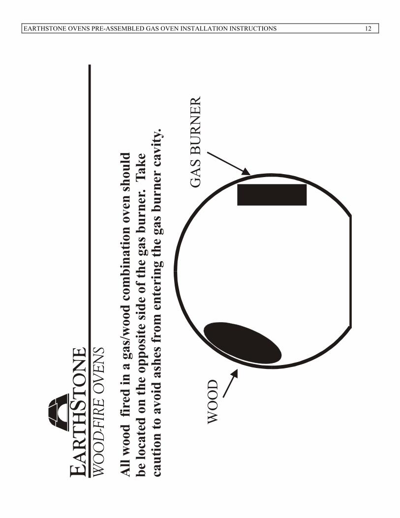
A SMALL AMOUNT OF WOOD CAN BE BURNED ON THE OPPOSITE SIDE OF THE GAS BURNER
TO ADD FLAVOR AND AESTHETIC VALUE IF DESIRED.
I�STRUCTIO�S TO PURCHASER
CONTACT LOCAL GAS SUPPLIER TO OBTAIN INFORMATION REGARDING INSTRUCTIONS TO BE FOLLOWED IN
EVENT USER SMELLS GAS. POST THESE INSTRUCTIONS IN A PROMINENT LOCATION.
FOR YOUR SAFETY
DO NOT STORE OR USE GASOLINE OR OTHER FLAMMABLE LIQUIDS OR VAPORS IN THE VICINITY OF THIS OR
ANY OTHER APPLIANCE.
WAR�I�G
IMPROPER INSTALLATION, ADJUSTMENT, ALTERATION, SERVICE OR MAINTENANCE CAN CAUSE PROPERTY
DAMAGE, INJURY OR DEATH. READ THE INSTALLATION, OPERATION AND MAINTENANCE INSTRUCTIONS
THOROUGHLY BEFORE INSTALLATION OR SERVICING THIS EQUIPMENT.
A CAUSE OF OVEN RELATED FIRES IS FAILURE TO MAINTAIN REQUIRED CLEARANCES (AIR SPACES) TO
COMBUSTIBLE MATERIALS. IT IS OF UTMOST IMPORTANCE THAT THIS OVEN BE INSTALLED ONLY IN
ACCORDANCE WITH THESE INSTRUCTIONS.
RETAI� THIS MA�UAL FOR FUTURE REFERE�CE.
OVE� DOOR MUST BE REMOVED
BEFORE FIRI�G A�D OPERATI�G OVE�.
EARTHSTO�E OVE�S – 6717 SA� FER�A�DO RD GLE�DALE CA 91201
TEL: 800-840-4915 - 818-553-1134 FAX: 818-553-1133
EARTHSTONE OVENS PRE-ASSEMBLED GAS OVEN INSTALLATION INSTRUCTIONS 2
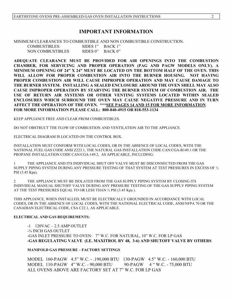
IMPORTA�T I�FORMATIO�
MINIMUM CLEARANCES TO COMBUSTIBLE AND NON COMBUSTIBLE CONSTRUCTION.
COMBUSTIBLES: SIDES 1” BACK 1”
NON COMBUSTIBLES SIDES 0” BACK 0”
ADEQUATE CLEARA�CE MUST BE PROVIDED FOR AIR OPE�I�GS I�TO THE COMBUSTIO�
CHAMBER, FOR SERVICI�G A�D PROPER OPERATIO� (PAG A�D PAGW MODELS O�LY). A
MI�IMUM OPE�I�G OF 24” X 24” MUST BE LOCATED O� THE BOTTOM HALF OF THE OVE�. THIS
WILL ALLOW FOR PROPER COMBUSTIO� AIR I�TO THE BUR�ER HOUSI�G. �OT HAVI�G
PROPER COMBUSTIO� AIR WILL CAUSE IMPROPER OPERATIO� A�D MAY CAUSE DAMAGE TO
THE BUR�ER SYSTEM. I�STALLI�G A SEALED E�CLOSURE AROU�D THE OVE� SHELL MAY ALSO
CAUSE IMPROPER OPERATIO� BY STARVI�G THE BUR�ER SYSTEM OF COMBUSTIO� AIR. THE
USE OF RETUR� AIR SYSTEMS OR OTHER VE�TI�G SYSTEMS LOCATED WITHI� SEALED
E�CLOSURES WHICH SURROU�D THE OVE� MAY CAUSE �EGATIVE PRESSURE A�D I� TUR�
AFFECT THE OPERATIO� OF THE OVE�. ***SEE PAGES 14 A�D 15 FOR MORE I�FORMATIO�
FOR MORE I�FORMATIO� PLEASE CALL: 800-840-4915 OR 818-553-1134
KEEP APPLIANCE FREE AND CLEAR FROM COMBUSTIBLES.
DO NOT OBSTRUCT THE FLOW OF COMBUSTION AND VENTILATION AIR TO THE APPLIANCE.
ELECTRICAL DIAGRAM IS LOCATED ON THE CONTROL BOX.
INSTALLATION MUST CONFORM WITH LOCAL CODES, OR IN THE ABSENCE OF LOCAL CODES, WITH THE
NATIONAL FUEL GAS CODE ANSI Z223.1, THE NATURAL GAS INSTALLATION CODE CAN/CGA-B149.1 OR THE
PROPANE INSTALLATION CODE CAN/CGA-149.2, AS APPLICABLE, INCLUDING:
1 THE APPLIANCE AND ITS INDIVIDUAL SHUT OFF VALVE MUST BE DISCONNECTED FROM THE GAS
SUPPLY PIPING SYSTEM DURING ANY PRESSURE TESTING OF THAT SYSTEM AT TEST PRESSURES IN EXCESS OF ½
PSI (3.45 Kpa).
2 THE APPLIANCE MUST BE ISOLATED FROM THE GAS SUPPLY PIPING SYSTEM BY CLOSING ITS
INDIVIDUAL MANUAL SHUTOFF VALVE DURING ANY PRESSURE TESTING OF THE GAS SUPPLY PIPING SYSTEM
AT THE TEST PRESSURES EQUAL TO OR LESS THAN ½ PSI (3.45 Kpa ).
THIS APPLIANCE, WHEN INSTALLED, MUST BE ELECTRICALLY GROUNDED IN ACCORDANCE WITH LOCAL
CODES, OR IN THE ABSENCE OF LOCAL CODES, WITH THE NATIONAL ELECTRICAL CODE, ANSI/NFPA 70 OR THE
CANADIAN ELECTRICAL CODE, CSA C22.1, AS APPLICABLE.
ELECTRICAL A�D GAS REQUIREME�TS:
-1 120VAC – 2.5 AMP OUTLET
-¾ INCH GAS OUTLET
-GAS INLET PRESSURE TO OVEN: 7” W.C. FOR NATURAL, 10” W.C. FOR LP GAS
-GAS REGULATI�G VALVE (I.E. MAXITROL RV 48, 3-6) A�D SHUTOFF VALVE BY OTHERS
MA�IFOLD GAS PRESSURE – FACTORY SETTI�GS
MODEL 160-PAGW 4.5” W.C. - .190,000 BTU 130-PAGW 4.5” W.C. - 160,000 BTU
MODEL 110-PAGW 4” W.C. - 90,000 BTU 90-PAGW 4 “ W.C. - 75,000 BTU
ALL OVENS ABOVE ARE FACTORY SET AT 7” W.C. FOR LP GAS
EARTHSTONE OVENS PRE-ASSEMBLED GAS OVEN INSTALLATION INSTRUCTIONS 3
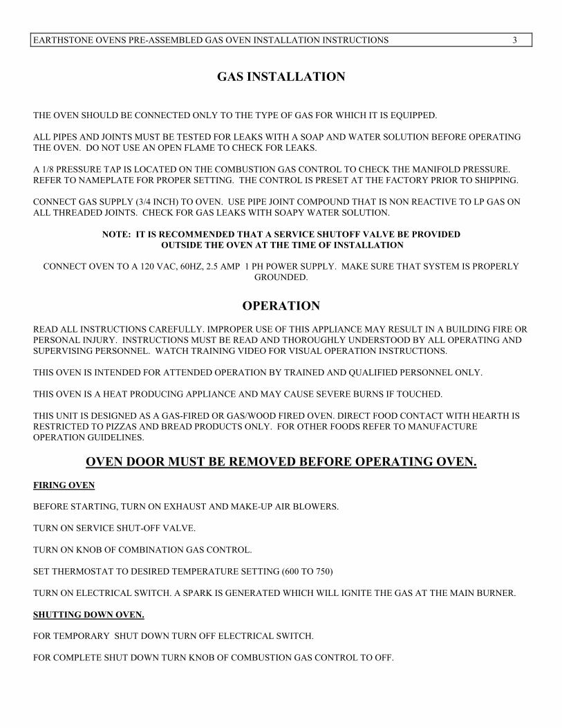
GAS I�STALLATIO�
THE OVEN SHOULD BE CONNECTED ONLY TO THE TYPE OF GAS FOR WHICH IT IS EQUIPPED.
ALL PIPES AND JOINTS MUST BE TESTED FOR LEAKS WITH A SOAP AND WATER SOLUTION BEFORE OPERATING
THE OVEN. DO NOT USE AN OPEN FLAME TO CHECK FOR LEAKS.
A 1/8 PRESSURE TAP IS LOCATED ON THE COMBUSTION GAS CONTROL TO CHECK THE MANIFOLD PRESSURE.
REFER TO NAMEPLATE FOR PROPER SETTING. THE CONTROL IS PRESET AT THE FACTORY PRIOR TO SHIPPING.
CONNECT GAS SUPPLY (3/4 INCH) TO OVEN. USE PIPE JOINT COMPOUND THAT IS NON REACTIVE TO LP GAS ON
ALL THREADED JOINTS. CHECK FOR GAS LEAKS WITH SOAPY WATER SOLUTION.
�OTE: IT IS RECOMME�DED THAT A SERVICE SHUTOFF VALVE BE PROVIDED
OUTSIDE THE OVE� AT THE TIME OF I�STALLATIO�
CONNECT OVEN TO A 120 VAC, 60HZ, 2.5 AMP 1 PH POWER SUPPLY. MAKE SURE THAT SYSTEM IS PROPERLY
GROUNDED.
OPERATIO�
READ ALL INSTRUCTIONS CAREFULLY. IMPROPER USE OF THIS APPLIANCE MAY RESULT IN A BUILDING FIRE OR
PERSONAL INJURY. INSTRUCTIONS MUST BE READ AND THOROUGHLY UNDERSTOOD BY ALL OPERATING AND
SUPERVISING PERSONNEL. WATCH TRAINING VIDEO FOR VISUAL OPERATION INSTRUCTIONS.
THIS OVEN IS INTENDED FOR ATTENDED OPERATION BY TRAINED AND QUALIFIED PERSONNEL ONLY.
THIS OVEN IS A HEAT PRODUCING APPLIANCE AND MAY CAUSE SEVERE BURNS IF TOUCHED.
THIS UNIT IS DESIGNED AS A GAS-FIRED OR GAS/WOOD FIRED OVEN. DIRECT FOOD CONTACT WITH HEARTH IS
RESTRICTED TO PIZZAS AND BREAD PRODUCTS ONLY. FOR OTHER FOODS REFER TO MANUFACTURE
OPERATION GUIDELINES.
OVE� DOOR MUST BE REMOVED BEFORE OPERATI�G OVE�.
FIRI�G OVE�
BEFORE STARTING, TURN ON EXHAUST AND MAKE-UP AIR BLOWERS.
TURN ON SERVICE SHUT-OFF VALVE.
TURN ON KNOB OF COMBINATION GAS CONTROL.
SET THERMOSTAT TO DESIRED TEMPERATURE SETTING (600 TO 750)
TURN ON ELECTRICAL SWITCH. A SPARK IS GENERATED WHICH WILL IGNITE THE GAS AT THE MAIN BURNER.
SHUTTI�G DOW� OVE�.
FOR TEMPORARY SHUT DOWN TURN OFF ELECTRICAL SWITCH.
FOR COMPLETE SHUT DOWN TURN KNOB OF COMBUSTION GAS CONTROL TO OFF.
EARTHSTONE OVENS PRE-ASSEMBLED GAS OVEN INSTALLATION INSTRUCTIONS 4
WOOD A�D/OR GAS FIRED COMBI�ATIO� PIZZA OVE�
OPERATI�G I�STRUCTIO�S
WARNING: READ ALL INSTRUCTIONS CAREFULLY. IMPROPER USE OF THIS APPLIANCE MAY RESULT IN A BUILDING FIRE OR PERSONAL INJURY. INSTRUCTIONS MUST BE READ AND THOROUGHLY UNDERSTOOD BY ALL OPERATING AND SUPERVISING PERSONNEL. WATCH TRAINING VIDEO FOR VISUAL OPERATION INSTRUCTIONS. THIS OVEN IS INTENDED FOR ATTENDED OPERATION BY TRAINED AND QUALIFIED PERSONNEL ONLY. THIS OVEN IS A HEAT PRODUCING APPLIANCE AND MAY CAUSE SEVERE BURNS IF TOUCHED.
DO NOT OVER FIRE. IF FLAME SPILLS FROM THE DOOR OPENING OR OVEN TEMPERATURE EXCEEDS 1000 DEGREES FAHRENHEIT, YOU ARE OVER FIRING. THIS UNIT IS DESIGNED AS A GAS OR GAS/WOOD FIRED OVEN. DIRECT FOOD CONTACT WITH THE HEARTH IS RESTRICTED TO PIZZAS AND BREAD PRODUCTS ONLY. FOR OTHER FOODS REFER TO MANUFACTURE
OPERATION GUIDELINES. ALL WOOD EMBERS BURNED INSIDE THE OVEN MUST BE PLACED DIRECTLY ON
THE OPPOSITE SIDE OF THE GAS BURNER (SEE DIAGRAM). WOOD SHOULD BE USED ONLY FOR FLAVORING
AND AESTHETIC VALUE, THE MAIN SOURCE OF HEAT SHOULD BE SUPPLIED BY THE GAS BURNER KEEP A PROPER FIRE EXTINGUISHER CLOSE TO THE OVEN AT ALL TIMES. EXTINGUISHER MUST BE RATED FOR USE ON WOOD FIRES. INSTRUCT ALL PERSONNEL ABOUT LOCATION AND USE OF THE FIRE EXTINGUISHER AND PROPER FIRE EMERGENCY PROCEDURES. a- Before starting, turn "ON" exhaust fan and make-up air blowers. b- Place a small amount of wood and kindling on the hearth over a fire-starter block. Light fire- starter. At any time do not use more than four pieces of wood, c- CAUTION: NEVER USE GASOLINE TYPE LANTERN FUEL, KEROSENE, CHARCOAL LIGHTER FLUID OR SIMILAR PRODUCTS TO START OR "FRESHEN UP" A FIRE IN THIS OVEN. KEEP ALL SUCH LIQUIDS WELL AWAY FROM THE OVEN WHEN IN USE. d. When the kindling is burning well, add larger pieces of firewood. USE WELL-SEASONED OR
DRIED WOOD ONLY.
e- Continue to add fuel as needed to maintain the desired heated rate, being careful to never over fire the unit. f- Whenever fuel is added, the fire may be poked and stirred with a wood handling tool. This will allow air to move through the fuel bed for proper combustion.
EARTHSTONE OVENS PRE-ASSEMBLED GAS OVEN INSTALLATION INSTRUCTIONS 5
g- When oven is heated to cooking temperature, move wood and ash to the opposite side of the gas burner
clear the hearth for cooking product. Insert ash barrier in front of burning wood. This is to separate the cooking area from the ash and wood. Clean cooking area as described in the DISPOSAL OF ASHES
section before commencing cooking procedures. Food must be placed on an appropriate cooking pan
before being set into the oven.
DOOR SHOULD BE CLOSED ONLY AFTER GAS BURNER IS TURNED OFF. 1. The first two fires should be small in order to properly cure the masonry in the unit. One fire each day for one
hour, for a total of six days. DO NOT USE PRODUCTS NOT SPECIFIED FOR USE WITH THIS OVEN. Maintain a minimum clearance of 36 inches in front of oven to combustible materials.
2. In case of out of control fire shut gas off and close door tightly. CAUTION--AVOID POSSIBLE HAZARDOUS FLARE-UPS AND SMOKE SPILLAGE. WHEN REMOVING DOOR
FROM IN FRONT OF DOOR OPENING, SLIDE DOOR OUT 2-3 INCHES FROM OPENING AND THEN WAIT 15 SECONDS BEFORE REMOVING DOOR COMPLETELY. FLARE-UPS CAN OCCUR WHEN DOOR IS OPENED SUDDENLY. KEEP FACE AND HANDS AWAY FROM DOOR OPENING.
3. Burn only seasoned or dried untreated solid wood fuel in the oven. DO NOT BURN OTHER FUELS IN THE
OVEN. DO NOT BURN CHARCOALS, COALS, TRASH/GARBAGE OR MANUFACTURED LOGS
(PROCESSED SOLID FUEL).
4. Firewood stored in the vicinity of the oven must be kept in a tightly-closed metal container; see maintenance
Instructions and NFPA 96. Keep firewood container closed at all times when not adding or removing firewood. Keep container a considerable distance from the oven and far away from sources of heat or ignition. DO NOT store matches, paper or other easily ignited items with firewood.
5. Provisions must be made to supply sufficient combustion air into the structure when using this appliance.
Combustion air must be supplied in accordance with local codes and the Uniform Mechanical Code and NFPA 96. Exhaust hood and make-up air blowers must be "ON" at all times during firing of the oven. If the exhaust hood power ventilator fails, close oven door to extinguish the fire and prevent temperature buildup in the hood duct which can activate the emergency fire suppression system.
6. Use only non-combustible hearth tools and cooking implements inside the oven. Store implements well away from
all combustible materials in a proper fixture which will capture any ashes or hot coals which may be carried out of the oven on the implements.
7. The fire should be built directly on the hearth; DO NOT elevate fire.
WOOD FIRE MAINTENANCE INSTRUCTIONS
WARNING:
READ ALL INSTRUCTIONS CAREFULLY. IMPROPER USE OR MAINTENANCE OF THIS APPLIANCE MAY RESULT IN A BUILDING FIRE OR PERSONAL INJURY.
1. Always keep area around the unit clean and clear of all combustible materials. Keep all furnishings, fuel and other
combustible objects a considerable distance away from the oven hearth.
2. DISPOSAL OF ASHES—Ashes from Ash Pan should be placed in a metal container with a tight-fitting lid. The closed container should be placed on a non-combustible floor or on the ground, well away from all combustible materials, pending final disposal. If the ashes are disposed by the burial in soil or otherwise locally dispersed, they
EARTHSTONE OVENS PRE-ASSEMBLED GAS OVEN INSTALLATION INSTRUCTIONS 6
should be retained in the closed container until all cinders have thoroughly cooled. After ashes have been removed mop down hearth with clean damp cloths.
3. Store wood in a cool, dry place well away from any source of flame or heat. If stored outside, keep the fuel covered
to protect from rain or snow. If stored inside, fuel should be kept in a covered metal container at least 6 inches above the floor. Keep paper, rags and other easily ignited materials away from wood fuel. Refer to NFPA 96 for
wood storage procedures. 4. At least at the end of each shift the area around the unit must be thoroughly cleaned of all wood, wood shavings,
embers, ashes and other refuse. All mats (if present, mats must be non-combustible) must be picked up and carefully swept along with the floor during this clean up. After clean up around the unit, brooms should be thoroughly wet down to extinguish hot coals, then stored well away from combustible materials.
5. Creosote - Formation and need for removal
WHEN WOOD IS BURNED SLOWLY, IT PRODUCES TAR AND OTHER ORGANIC VAPORS, WHICH COMBINE WITH EXPELLED MOISTURE TO FORM CREOSOTE. THE CREOSOTE VAPORS CONDENSE IN THE RELATIVELY COOL OVEN FLUE AND EXHAUST HOOD OF DUCT, PARTICULARLY A SLOW
burning fire. As a result, creosote residue accumulates on the flue lining and exhaust hood. When ignited, this creosote makes an extremely hot fire. The oven flue, exhaust duct and power ventilator should be inspected at least twice monthly during normal use to determine if creosote buildup has occurred. If creosote and/or grease has accumulated, it should be removed to reduce the risk of fire. Experienced chimney and duct servicing personnel who are qualified in the removal of both creosote and grease from flues and ducts should be contracted to do the inspection and cleaning. The inspection and cleaning schedule must be adjusted as needed to prevent the buildup of creosote and/or grease. More frequent inspections and cleanings are indicated when excessive buildup occurs between regular inspections. The rate of accumulation can increase whenever 1) there is a change in the use of the oven 2) when the type or moisture content of the firewood changes 3) when other variables change. The oven, exhaust hood and grease filters should be cleaned on a daily basis. The Grease filters can be removed and cleaned in a dishwasher or sink. Refer to the NFPA 96 requirements and the Exhaust Hood or Grease Duct manufacturer's instructions for inspection, maintenance and cleaning of the venting system.
DO NOT CLEAN UNIT, HOOD OR VENT WHILE HOT OR WHILE OVEN IS BEING FIRED.
6. The entire unit and vent system should be inspected frequently for proper fit, operation and soundness of parts.
If any malfunctioning parts, leakage, deterioration, or other problems are noted, contact your dealer to inspect and repair the unit, or qualified ventilation repair service to inspect and repair the vent system. DO NOT OPERATE THE UNIT IF INSTALLED OR FUNCTIONING IMPROPERLY.
7. All maintenance must be performed by qualified personnel. 8. Refer to NFPA 96 for procedures for inspection, cleaning and maintenance for solid fuel cooking.
9. SERVICE OF OVEN TEMP. MONITORING EQUIPMENT
A) Replace with Temp. gauge rated 6-14 VDC, Temp. range -580F to 9320F. (AJ Antunes – TTC)
B) Replace AC adapter with U.L. listed plug-in class 2 transformer rated input 120 VAC, 60 HZ,
9 Watts, output 12 VDC, 200 Ma.
C) Replace Thermocouple with a metal sheathed Type-"K" thermocouple, Min. 6 ft. 10. Save these instructions for future reference.
EARTHSTONE OVENS PRE-ASSEMBLED GAS OVEN INSTALLATION INSTRUCTIONS 7
GAS BUR�ER MAI�TE�A�CE
WAR�I�G:
IMPROPER MAI�TE�A�CE OF THIS APPLIA�CE MAY RESULT I� A BUILDI�G FIRE OR PERSO�AL I�JURY.
DO NOT CLEAN OR SERVICE OVEN, HOOD OR VENT WHILE HOT OR WHILE OVEN IS IN OPERATION.
CONTACT THE FACTORY OR FACTORY REPRESENTATIVE OR A LOCAL SERVICE COMPANY TO PERFORM
MAINTENANCE AND REPAIRS.
1. CLEAN OVEN REGULARLY WITH RECOMMENDATION CLEANING AGENTS AS NECESSARY.
2. DISCONNECT POWER SUPPLY TO THE OVEN BEFORE CLEANING OR SERVICING.
3 TO REMOVE BURNER FOR CLEANING FOLLOW THESE STEPS:
DISCONNECT CABLE FROM SPARK IGNITER.
UNSCREW FITTING OF GAS SUPPLY LINE WHICH IS NEAREST TO BURNER ASSEMBLY THIS SUPPLY LINE
CONNECTS THE GAS VALVE TO BURNER ASSEMBLY.
TILT OPPOSITE END OF BURNER UP AND SLIDE BURNER DOWN FROM BURNER ENCLOSURE.
CLEAN BURNER WITH WIRE BRUSH TO ENSURE THAT ALL THE JET HOLES ARE CLEAN.
4. TO REPLACE BURNER AFTER CLEANING FOLLOW THESE STEPS:
SLIDE BURNER INTO ENCLOSURE BY INSERTING END OPPOSITE TO GAS CONNECTION FIRST THEN THE
REMAINING OF THE BURNER UNTIL BURNER RESTS HORIZONTALLY IN BURNER ENCLOSURE.
CONNECT GAS SUPPLY LINE TO BURNER.
CONNECT CABLE TO SPARK IGNITER.
�OTE: ALWAYS CHECK FOR GAS LEAKS USI�G A SOAPY SOLUTIO�.
�EVER USE OPE� FLAME TO CHECK FOR GAS LEAKS
EARTHSTONE OVENS PRE-ASSEMBLED GAS OVEN INSTALLATION INSTRUCTIONS 8
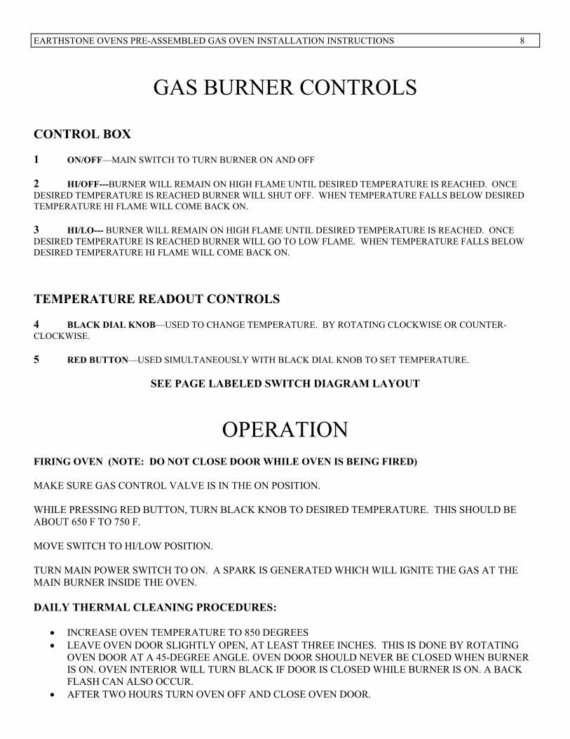
GAS BURNER CONTROLS
CO�TROL BOX
1 O�/OFF—MAIN SWITCH TO TURN BURNER ON AND OFF
2 HI/OFF---BURNER WILL REMAIN ON HIGH FLAME UNTIL DESIRED TEMPERATURE IS REACHED. ONCE
DESIRED TEMPERATURE IS REACHED BURNER WILL SHUT OFF. WHEN TEMPERATURE FALLS BELOW DESIRED
TEMPERATURE HI FLAME WILL COME BACK ON.
3 HI/LO--- BURNER WILL REMAIN ON HIGH FLAME UNTIL DESIRED TEMPERATURE IS REACHED. ONCE
DESIRED TEMPERATURE IS REACHED BURNER WILL GO TO LOW FLAME. WHEN TEMPERATURE FALLS BELOW
DESIRED TEMPERATURE HI FLAME WILL COME BACK ON.
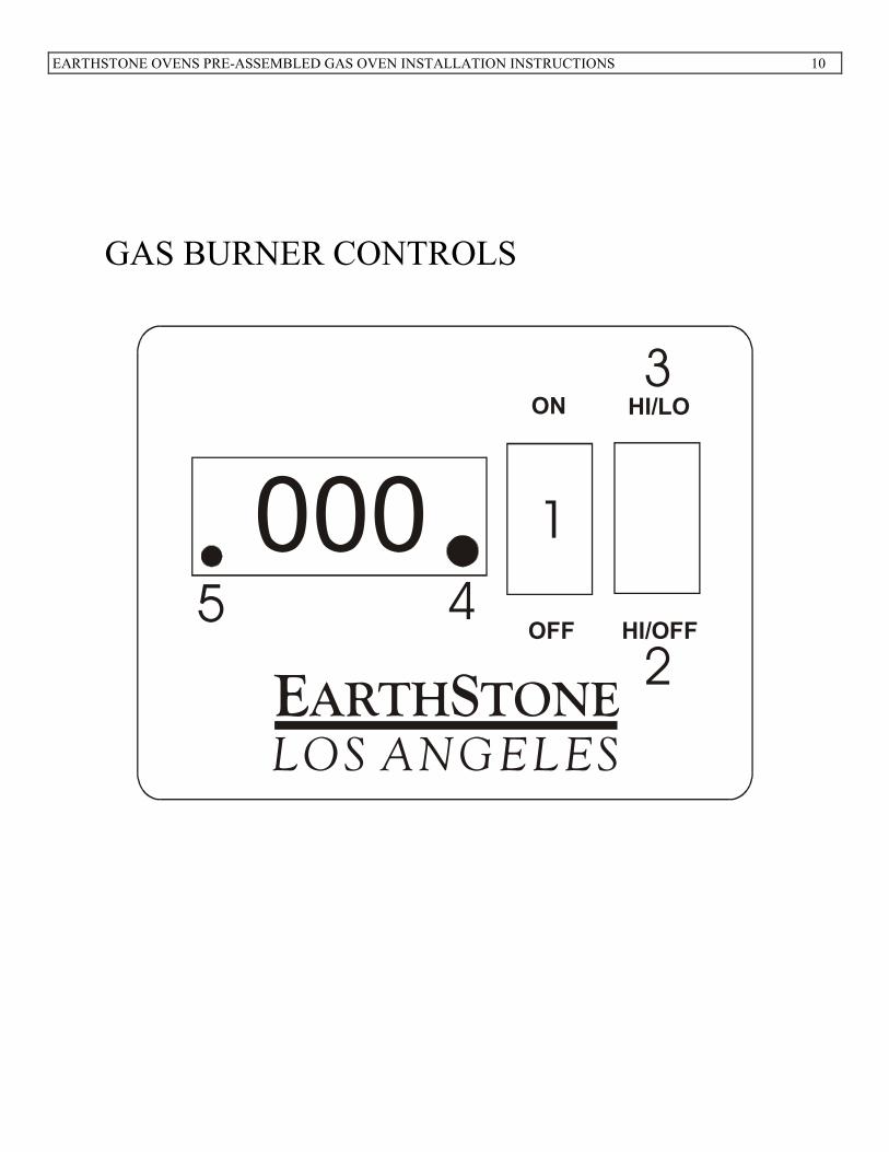
TEMPERATURE READOUT CO�TROLS
4 BLACK DIAL K�OB—USED TO CHANGE TEMPERATURE. BY ROTATING CLOCKWISE OR COUNTER-
CLOCKWISE.
5 RED BUTTO�—USED SIMULTANEOUSLY WITH BLACK DIAL KNOB TO SET TEMPERATURE.
SEE PAGE LABELED SWITCH DIAGRAM LAYOUT
OPERATION
FIRI�G OVE� (�OTE: DO �OT CLOSE DOOR WHILE OVE� IS BEI�G FIRED)
MAKE SURE GAS CONTROL VALVE IS IN THE ON POSITION.
WHILE PRESSING RED BUTTON, TURN BLACK KNOB TO DESIRED TEMPERATURE. THIS SHOULD BE
ABOUT 650 F TO 750 F.
MOVE SWITCH TO HI/LOW POSITION.
TURN MAIN POWER SWITCH TO ON. A SPARK IS GENERATED WHICH WILL IGNITE THE GAS AT THE
MAIN BURNER INSIDE THE OVEN.
DAILY THERMAL CLEA�I�G PROCEDURES:
• INCREASE OVEN TEMPERATURE TO 850 DEGREES
• LEAVE OVEN DOOR SLIGHTLY OPEN, AT LEAST THREE INCHES. THIS IS DONE BY ROTATING
OVEN DOOR AT A 45-DEGREE ANGLE. OVEN DOOR SHOULD NEVER BE CLOSED WHEN BURNER
IS ON. OVEN INTERIOR WILL TURN BLACK IF DOOR IS CLOSED WHILE BURNER IS ON. A BACK
FLASH CAN ALSO OCCUR.
• AFTER TWO HOURS TURN OVEN OFF AND CLOSE OVEN DOOR.
EARTHSTONE OVENS PRE-ASSEMBLED GAS OVEN INSTALLATION INSTRUCTIONS 9
• DO NOT USE ANY CLEANING AGENTS IN THE OVEN
SHUTTI�G DOW� OVE�
TURN MAIN POWER SWITCH TO OFF POSITION.
IF OVEN IS BEING SHUT DOWN FOR THE NIGHT, GAS CONTROL VALVE SHOULD BE TURNED
TO OFF POSITION.
SAVE THESE I�STRUCTIO�S.
IF YOU HAVE ANY QUESTIONS PLEASE CALL 800-840-4915 or 818-553-1134
EARTHSTONE OVENS PRE-ASSEMBLED GAS OVEN INSTALLATION INSTRUCTIONS 10
GAS BURNER CONTROLS
E SARTH TONE
LOS ANGELES
OFF
ON HI/LO
HI/OFF
000 1
2
3
45
EARTHSTONE OVENS PRE-ASSEMBLED GAS OVEN INSTALLATION INSTRUCTIONS 11
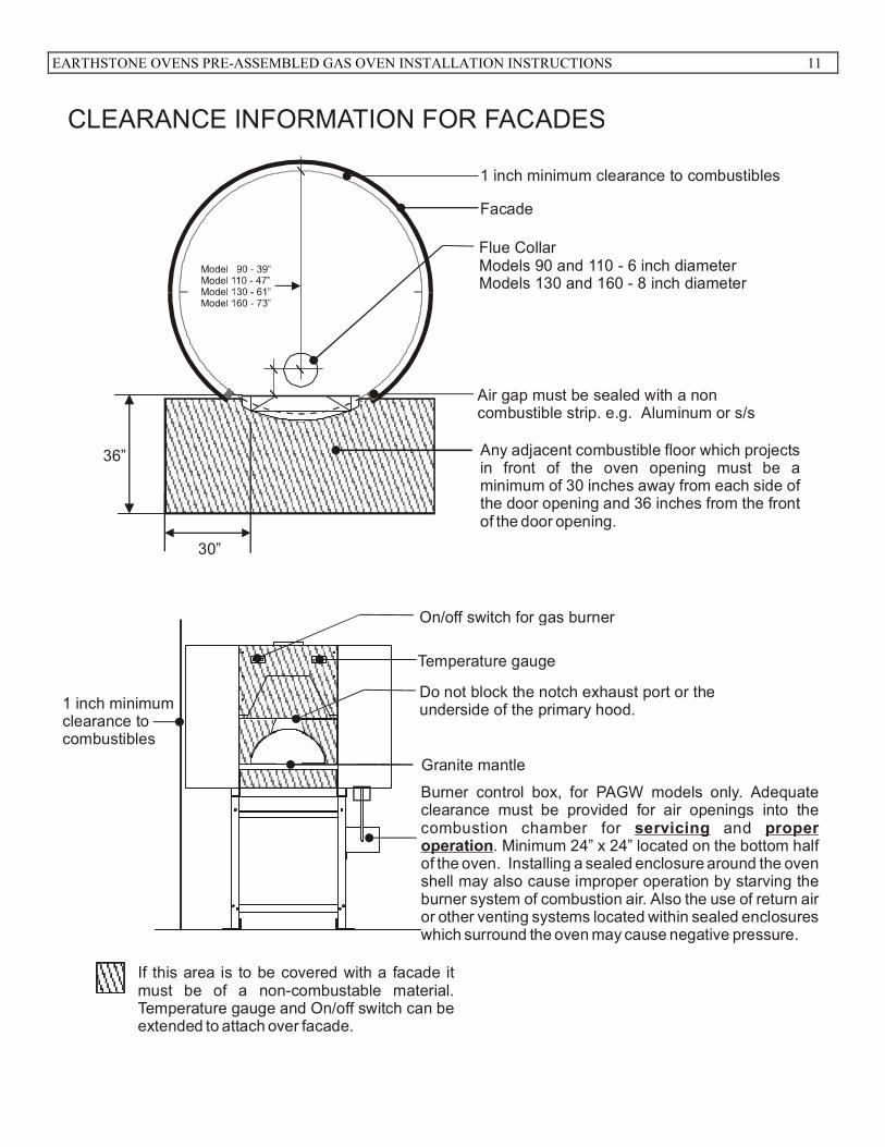
30”
36”
Granite mantle
Temperature gauge
On/off switch for gas burner
Burner control box, for PAGW models only. Adequate clearance must be provided for air openings into the combustion chamber for and
. Minimum 24” x 24” located on the bottom half of the oven. Installing a sealed enclosure around the oven shell may also cause improper operation by starving the burner system of combustion air. Also the use of return air or other venting systems located within sealed enclosures which surround the oven may cause negative pressure.
servicing proper operation
If this area is to be covered with a facade it must be of a non-combustable material. Temperature gauge and On/off switch can be extended to attach over facade.
1 inch minimum clearance to combustibles
Facade
Flue CollarModels 90 and 110 - 6 inch diameterModels 130 and 160 - 8 inch diameter
Any adjacent combustible floor which projects in front of the oven opening must be a minimum of 30 inches away from each side of the door opening and 36 inches from the front of the door opening.
Air gap must be sealed with a noncombustible strip. e.g. Aluminum or s/s
CLEARANCE INFORMATION FOR FACADES
Do not block the notch exhaust port or the underside of the primary hood.1 inch minimum
clearance tocombustibles
EARTHSTONE OVENS PRE-ASSEMBLED GAS OVEN INSTALLATION INSTRUCTIONS 12
GAS BURNER
WOOD
All
wood
fi
red
in
a g
as/
wood
com
bin
ati
on
oven
sh
ou
ldb
e lo
cate
d o
n t
he o
pp
osi
te s
ide
of
the
gas
bu
rn
er.
T
ak
eca
uti
on
to a
void
ash
es
from
en
teri
ng
th
e g
as
bu
rn
er
cav
ity.
ES
AR
TH
TO
NE
WO
OD
-FIR
E O
VE
NS
EARTHSTONE OVENS PRE-ASSEMBLED GAS OVEN INSTALLATION INSTRUCTIONS 13
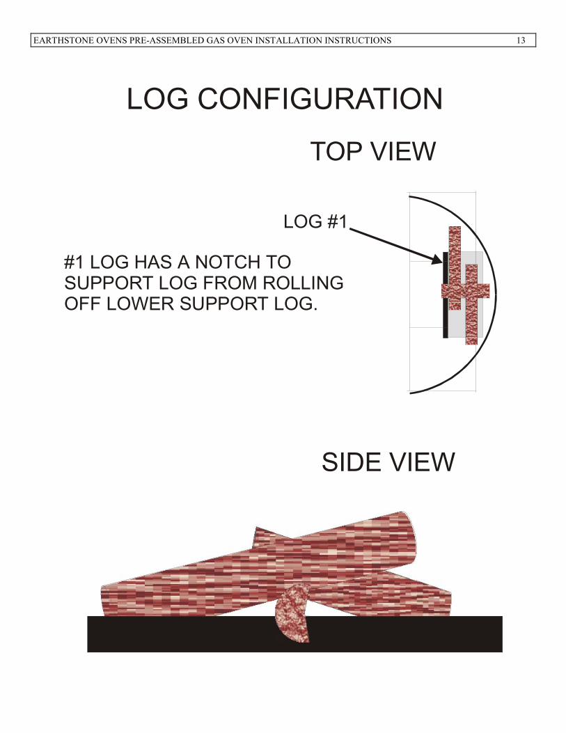
LOG CONFIGURATION
TOP VIEW
SIDE VIEW
LOG #1
#1 LOG HAS A NOTCH TOSUPPORT LOG FROM ROLLINGOFF LOWER SUPPORT LOG.
EARTHSTONE OVENS PRE-ASSEMBLED GAS OVEN INSTALLATION INSTRUCTIONS 14
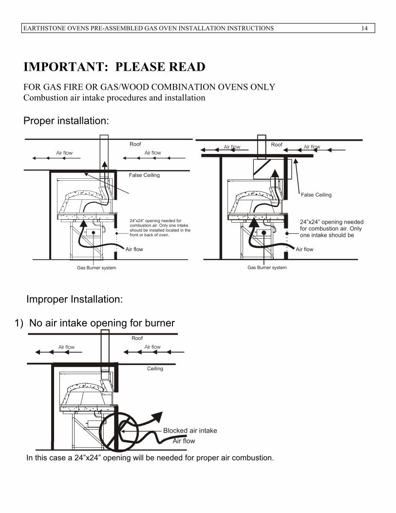
IMPORTA�T: PLEASE READ
FOR GAS FIRE OR GAS/WOOD COMBINATION OVENS ONLY
Combustion air intake procedures and installation
Proper installation:
Roof
False Ceiling
Air flow Air flow
24”x24” opening needed for combustion air. Only one intake should be installed located in the front or back of oven.
Gas Burner system
Air flow
Roof
False Ceiling
Air flow Air flow
24”x24” opening needed for combustion air. Only one intake should be
Gas Burner system
Air flow
Improper Installation:
1) No air intake opening for burner
Roof
Ceiling
Air flow Air flow
Air flow
Blocked air intake
In this case a 24”x24” opening will be needed for proper air combustion.
EARTHSTONE OVENS PRE-ASSEMBLED GAS OVEN INSTALLATION INSTRUCTIONS 15
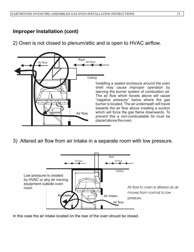
Improper Installation (cont) 2) Oven is not closed to plenum/attic and is open to HVAC airflow.
Roof
Ceiling
Air flow Air flow
Air flow
Installing a sealed enclosure around the oven shell may cause improper operation by starving the burner system of combustion air. The air flow which travels above will cause “negative pressure” below where the gas burner is located. The air underneath will travel towards the air flow above creating a suction which will force the gas flame downwards. To prevent this a non-combustable lid must be placed above the oven.
3) Altered air flow from air intake in a separate room with low pressure.
Roof
Ceiling
Air flow Air flow
Air IntakeAir Intake
Air flow
Air flow to oven is altered as air
moves from normal to low
pressure
Low pressure is createdby HVAC or any air movingequipment outside ovenroom
In this case the air intake located on the rear of the oven should be closed.
EARTHSTONE OVENS PRE-ASSEMBLED GAS OVEN INSTALLATION INSTRUCTIONS 16
GAS FIRE START-UP PROCEDURES
� MAKE SURE ALL POWER PLUGS ARE CONNECTED.
� GAS PRESSURE, BEFORE OVEN VALVE, SHOULD BE 7” W.C. FOR NATURAL GAS
AND 10” W.C. FOR LP GAS. GAS FIRE MANIFOLD PRESSURE IS SET AT THE
FACTORY. PLEASE SEE CHART ON THE BOTTOM OF PAGE 2.
� ADEQUATE CLEARANCE MUST BE PROVIDED FOR AIR OPENINGS INTO THE
COMBUSTION CHAMBER, FOR SERVICING AND PROPER OPERATION (PAG AND
PAGW MODELS ONLY). A MI�IMUM OPE�I�G OF 24” X 24” MUST BE LOCATED
O� THE BOTTOM HALF OF THE OVE�. THIS AREA CA��OT BE BLOCKED
� CHECK TO SEE THAT MAIN GAS VALVE ON GAS BURNER CONTROLLER BOX IS
ON.
� SET TEMPERATURE CONTROLLER TO BELOW 200 DEGREES BY HOLDING DOWN
RED BUTTON AND TURNING BLACK KNOB COUNTER CLOCKWISE TO DECREASE
AND CLOCKWISE TO INCREASE.
� REMOVE OVE� DOOR. THE DOOR SHOULD �OT BE CLOSED WHE� OVE� IS
FIRED. WITH A 2 SIDED OVE� YOU CA� HAVE O�E DOOR CLOSED.
� MOVE HI/LO – HI/OFF SWITCH TO “HI/LO”. (UPWARD CLICK)
� TURN ON/OFF SWITCH TO “ON”. INITIALLY OVEN MAY NEED TO BE TURNED ON
AND OFF 4 OR 5 TIMES (IN 1 SECOND INTERVALS) IN ORDER TO BLEED THE GAS
PIPE.
CLICK “ON” WAIT 1 SEC, TURN OFF.
CLICK “ON” WAIT 1 SEC, TURN OFF.
LONGER PIPE LENGTHS MAY REQUIRE MORE BLEEDING.
ALLOW OVE� TO FIRE FOR AT LEAST 5 HOURS AT LOW FLAME FOR 2 DAYS
AFTER 2 DAY FIRI�G ADJUST TEMPERATURE TO �ORMAL OPERATI�G RA�GE 600F-750F
Oven curing is a process of removing moisture from the oven that has accumulated during
the oven installation. If you still see moisture from the oven you may need to cure the oven
for a few more days. Improper curing may cause small pieces of the oven to pop. Although
this is not harmful to the oven in anyway, please follow these procedures.
EARTHSTONE OVENS PRE-ASSEMBLED GAS OVEN INSTALLATION INSTRUCTIONS 17
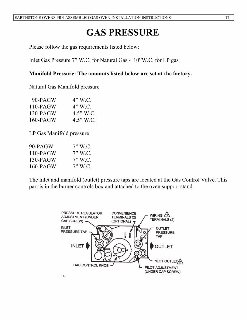
GAS PRESSURE
Please follow the gas requirements listed below:
Inlet Gas Pressure 7” W.C. for Natural Gas - 10”W.C. for LP gas
Manifold Pressure: The amounts listed below are set at the factory.
Natural Gas Manifold pressure
90-PAGW 4” W.C.
110-PAGW 4” W.C.
130-PAGW 4.5” W.C.
160-PAGW 4.5” W.C.
LP Gas Manifold pressure
90-PAGW 7” W.C.
110-PAGW 7” W.C.
130-PAGW 7” W.C.
160-PAGW 7” W.C.
The inlet and manifold (outlet) pressure taps are located at the Gas Control Valve. This
part is in the burner controls box and attached to the oven support stand.