Embed Size (px)
Citation preview
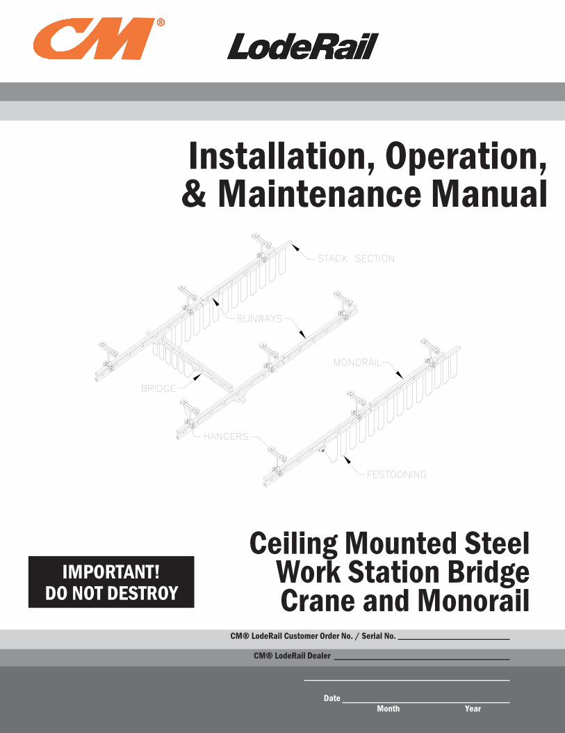
IMPORTANT!DO NOT DESTROY
Installation, Operation, & Maintenance Manual
Month Year
CM® LodeRail Dealer
Date
Ceiling Mounted Steel Work Station Bridge Crane and Monorail
CM® LodeRail Customer Order No. / Serial No.
TABLE OF CONTENTSIntroduction................................................................................................................................................1
Installation....Step.1..-.Pre-assembly...........................................................................................................................1
.....Step.2..-.Hanger.Installation.................................................................................................................2-4
.....Step.3..-.Runway.Installation................................................................................................................5-6
.....Step.4..-.Splice.Joint.Installation.............................................................................................................7
.....Step.5..-.Bridge.and.End.Truck.Installation..........................................................................................8-9
.....Step.6..-.Hoist.Trolley.Installation.....................................................................................................10-11
.....Step.7..-.Festoon.Stack.Section.Installation.........................................................................................12
.....Step.8..-.Festooning.Installation.......................................................................................................13-15
.....Step.9..-.Bridge.and.Runway.Tagline.Installation............................................................................15-16
.....Step.10..-.Optional.Accessories.......................................................................................................16-17
.....Step.11..-.Final.Steps............................................................................................................................17
Applied.Forces.to.the.Supporting.Structure..................................................................................18
Sway.Bracing.and.Thrust.Bracing.Guidelines..............................................................................19
Crane.Operator.Instructions...............................................................................................................20
General.Operational.Suggestions....................................................................................................20
Limited.Warranty....................................................................................................................................21
Inspection.and.Maintenance.Schedule...........................................................................................22
Questions?..Concerns?..Comments?..Please.call.(800).888-0985.(US.and.Canada).or(716).689-5400.(outside.US).

INTRODUCTIONThank.you.for.choosing.CM®.LodeRail.Ceiling.Mounted.Work.Station.Cranes.to.solve.your.material.handling.needs..The.innovative.design.and.heavy-duty.construction.of.the.CM®.LodeRail.Work.Station.Cranes.will.provide.asuperior.quality.product.that.will.offer.years.of.long.term.value..All.CM®.LodeRail.cranes.are.pre-engineered.for.powered.hoist.operation..The.hoist.weight.allowance.is.15%.of.the.crane’s.capacity.(for.example,.a.crane.rated.for.1000.pounds,.allows.for.a.1000-pound.live.load.plus.150.pounds.for.the.weight.of.the.hoist)..There.is.also.anallowance.of.25%.of.the.crane.capacity.for.impact.caused.by.hoist.use..CM®.LodeRail.Work.Station.Cranes.willprovide.many.years.of.dependable.service.by.following.the.installation.and.maintenance.procedures.describedherein.
Dimensions contained in this installation manual are for reference only and may differ for your particular application. Please refer to the enclosed General Arrangement Drawing for actual dimensions.
Normal safety precautions:..These.include,.but.are.not.limited.to:•. Checking.for.obstructions.in.crane.travel•. Checking.that.all.bolts.and.threaded.rods.are.tight.and.have.lockwashers•. Making.sure.that.end.stops.are.in.place•. Making.sure.that.festooning.cannot.be.snagged.or.pinched,.whether.it.is.electric.or.pneumatic
For.additional.safety.precautions,.see.page.20.
INSTALLATION
STEP 1 - PRE-ASSEMBLY1.1. Read.entire.installation.manual.before.you.begin.installing.your.crane.1.2. Check.packing.list.to.make.sure.correct quantity.of.parts.is.included.1.3. Tools.and.materials.typically.needed.to.assemble.crane.are.as.follows:. . •.Hand.tools. . . •.Powered.metal-cutting.saw. . •.Leveling.tools. . . •.Steel.shims.(for.flush.mounted.hangers). . •.Ladders/man.lifts. . •.Torque.wrench.(able.to.torque.up.to.200-ft..lb.)
WARNINGEquipment.described.herein.is.not.designed.for,.and.should.not.be.used.for,.lifting,.supporting.or.transporting.humans...Failure.to.comply.with.any.one.of.the.limitations.noted.herein.can.result.in.serious.bodily.injury.and/or.property.damage...Check.State.and.Local.regulations.for.any.additional.requirements.
WARNINGCrane.cannot.be.utilized.as.a.ground:..A.separate.ground.wire.is.required...For.example,.systems.with.3-phase.power.require.three.conductors.plus.one.ground.wire.
WARNINGBefore.installing.any.crane.system,.it.is.critical.you.determine.that.your.building.will.safely.support.the.loads..CM®.LodeRail.assumes.no.responsibility.for.adequacy.or.integrity.of.the.mounting.surface.
WARNINGSway.bracing.is.required.(except.when.using.flush.mounted.hangers)...For.more.information.see.page.19.
WARNINGReference.the.American.Institute.of.Steel.Construction.(AISC).Manual.of.Steel.Construction.(9th.edition),.Part.5,.Specification.for.Structural.Joints.using.ASTM.A325.or.A490.Bolts.(section.8.d.2).for.the.proper.procedures.to.follow.when.using.any.torque-tightening.method.
..TIP: Packing.list.can.be.found.in.plastic.pocket.attached.to.the.hardware.box:..General.Arrangement.Drawing
. and.additional.inserts.can.be.found.enclosed.in.this.installation.manual.
11/11
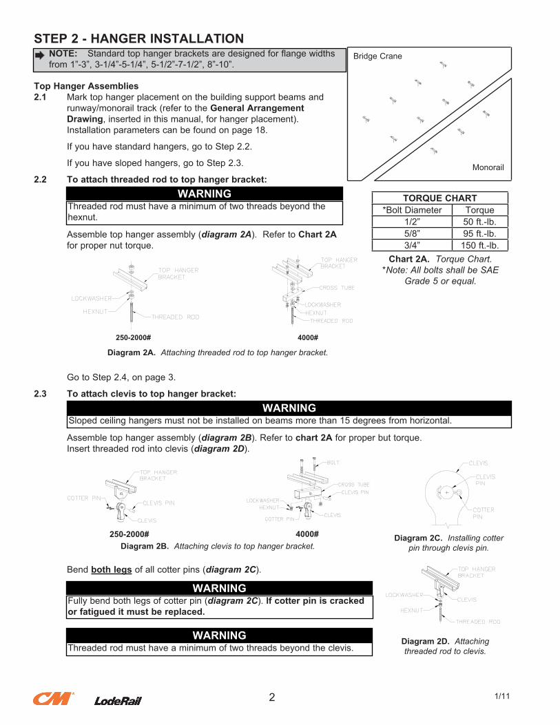
STEP 2 - HANGER INSTALLATION
Top Hanger Assemblies2.1. Mark.top.hanger.placement.on.the.building.support.beams.and. runway/monorail.track.(refer.to.the.General Arrangement. Drawing,.inserted.in.this.manual,.for.hanger.placement).. Installation.parameters.can.be.found.on.page.18.
. If.you.have.standard.hangers,.go.to.Step.2.2.
. If.you.have.sloped.hangers,.go.to.Step.2.3.
2.2 To attach threaded rod to top hanger bracket:
. Assemble.top.hanger.assembly.(diagram 2A)...Refer.to.Chart 2A
. for.proper.nut.torque.
. Go.to.Step.2.4,.on.page.3.
2.3 To attach clevis to top hanger bracket:
. Assemble.top.hanger.assembly.(diagram 2B)..Refer.to.chart 2A.for.proper.but.torque.
. Insert.threaded.rod.into.clevis.(diagram 2D).
. Bend.both legs.of.all.cotter.pins.(diagram 2C).
.NOTE:. Standard.top.hanger.brackets.are.designed.for.flange.widths
.from.1”-3”,.3-1/4”-5-1/4”,.5-1/2”-7-1/2”,.8”-10”.
WARNINGThreaded.rod.must.have.a.minimum.of.two.threads.beyond.the.hexnut.
Chart 2A. Torque Chart.*Note: All bolts shall be SAE
Grade 5 or equal.
4000#250-2000#
Diagram 2A. Attaching threaded rod to top hanger bracket.
2
Bridge.Crane
Monorail
TORQUE CHART*Bolt.Diameter Torque
1/2” 50.ft.-lb.5/8” 95.ft.-lb.3/4” 150.ft.-lb.
1/11
WARNINGSloped.ceiling.hangers.must.not.be.installed.on.beams.more.than.15.degrees.from.horizontal.
250-2000# 4000#Diagram 2B. Attaching clevis to top hanger bracket.
Diagram 2C. Installing cotter pin through clevis pin.
WARNINGThreaded.rod.must.have.a.minimum.of.two.threads.beyond.the.clevis.
WARNINGFully.bend.both.legs.of.cotter.pin.(diagram 2C)..If cotter pin is cracked or fatigued it must be replaced.
Diagram 2D. Attachingthreaded rod to clevis.
STEP 2 - HANGER INSTALLATION (CONTINUED)
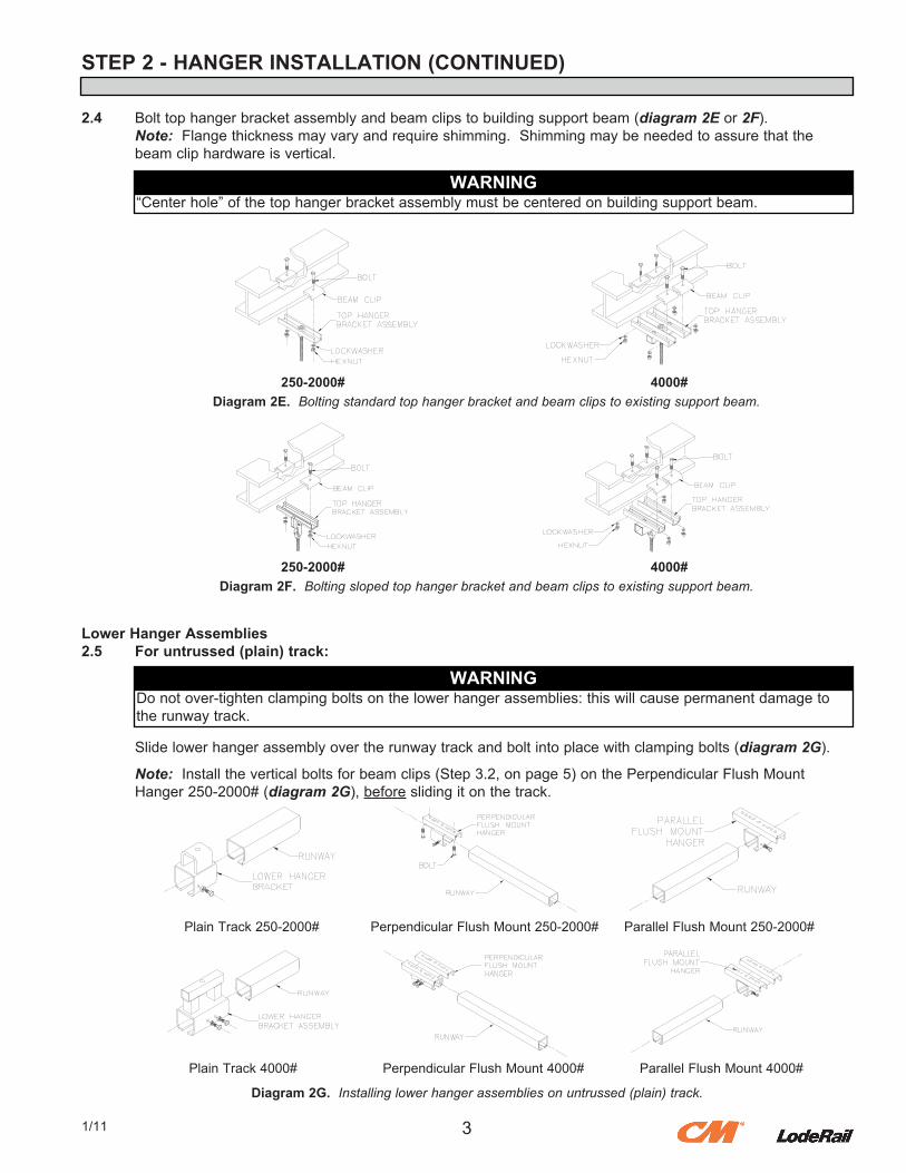
2.4. Bolt.top.hanger.bracket.assembly.and.beam.clips.to.building.support.beam.(diagram 2E.or.2F).. Note:..Flange.thickness.may.vary.and.require.shimming...Shimming.may.be.needed.to.assure.that.the. beam.clip.hardware.is.vertical.
Lower Hanger Assemblies2.5 For untrussed (plain) track:
.
. Slide.lower.hanger.assembly.over.the.runway.track.and.bolt.into.place.with.clamping.bolts.(diagram 2G).
. Note:..Install.the.vertical.bolts.for.beam.clips.(Step.3.2,.on.page.5).on.the.Perpendicular.Flush.Mount
. Hanger.250-2000#.(diagram 2G),.before.sliding.it.on.the.track.
WARNING
250-2000# 4000#Diagram 2E. Bolting standard top hanger bracket and beam clips to existing support beam.
“Center.hole”.of.the.top.hanger.bracket.assembly.must.be.centered.on.building.support.beam.
31/11
250-2000# 4000#Diagram 2F. Bolting sloped top hanger bracket and beam clips to existing support beam.
WARNINGDo.not.over-tighten.clamping.bolts.on.the.lower.hanger.assemblies:.this.will.cause.permanent.damage.to.the.runway.track.
Plain.Track.250-2000# Perpendicular.Flush.Mount.250-2000# Parallel.Flush.Mount.250-2000#
Plain.Track.4000# Perpendicular.Flush.Mount.4000# Parallel.Flush.Mount.4000#
Diagram 2G. Installing lower hanger assemblies on untrussed (plain) track.
STEP 2 - HANGER INSTALLATION (CONTINUED)
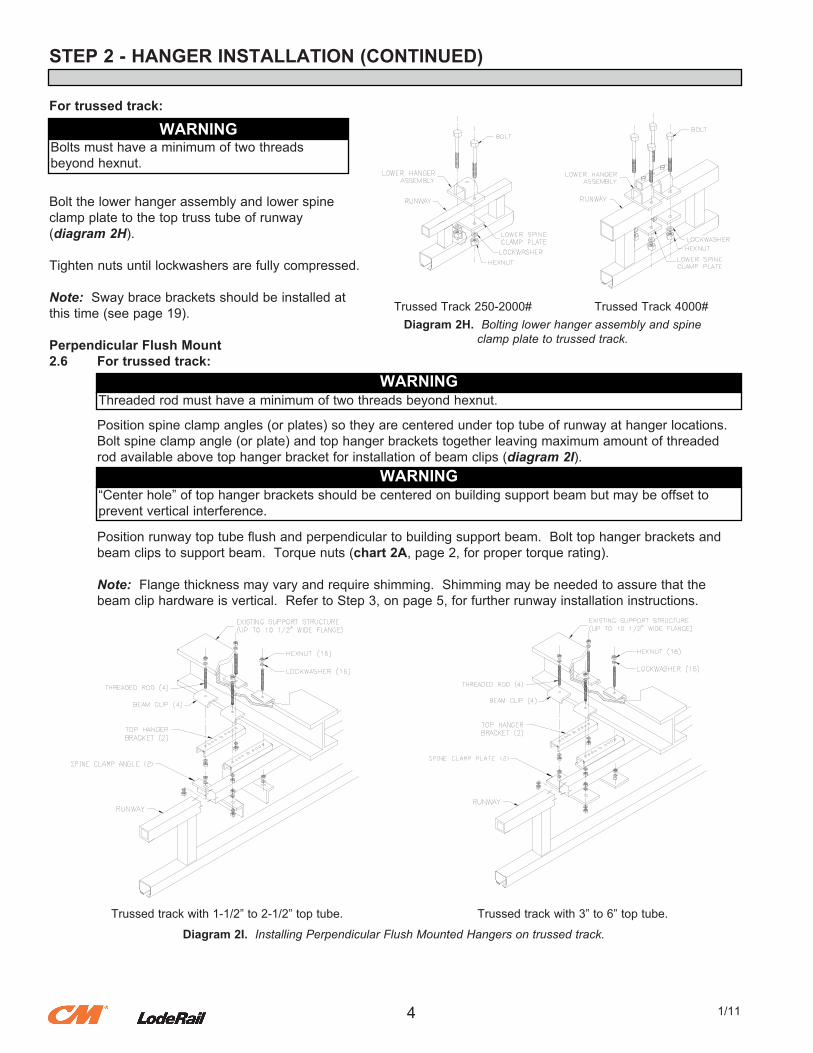
For trussed track:
Bolt.the.lower.hanger.assembly.and.lower.spineclamp.plate.to.the.top.truss.tube.of.runway(diagram 2H).
Tighten.nuts.until.lockwashers.are.fully.compressed.
Note:..Sway.brace.brackets.should.be.installed.at.this.time.(see.page.19).
Perpendicular Flush Mount2.6 For trussed track:
. Position.spine.clamp.angles.(or.plates).so.they.are.centered.under.top.tube.of.runway.at.hanger.locations..
. Bolt.spine.clamp.angle.(or.plate).and.top.hanger.brackets.together.leaving.maximum.amount.of.threaded
. rod.available.above.top.hanger.bracket.for.installation.of.beam.clips.(diagram 2I).
. Position.runway.top.tube.flush.and.perpendicular.to.building.support.beam...Bolt.top.hanger.brackets.and
. beam.clips.to.support.beam...Torque.nuts.(chart 2A,.page.2,.for.proper.torque.rating).
. Note:..Flange.thickness.may.vary.and.require.shimming...Shimming.may.be.needed.to.assure.that.the
. beam.clip.hardware.is.vertical...Refer.to.Step.3,.on.page.5,.for.further.runway.installation.instructions.
WARNINGBolts.must.have.a.minimum.of.two.threads.beyond.hexnut.
Trussed.Track.250-2000# Trussed.Track.4000#Diagram 2H. Bolting lower hanger assembly and spine
clamp plate to trussed track.
4 1/11
WARNINGThreaded.rod.must.have.a.minimum.of.two.threads.beyond.hexnut.
WARNING“Center.hole”.of.top.hanger.brackets.should.be.centered.on.building.support.beam.but.may.be.offset.toprevent.vertical.interference.
Diagram 2I. Installing Perpendicular Flush Mounted Hangers on trussed track.
Trussed.track.with.1-1/2”.to.2-1/2”.top.tube. Trussed.track.with.3”.to.6”.top.tube.
STEP 3 - RUNWAY INSTALLATION
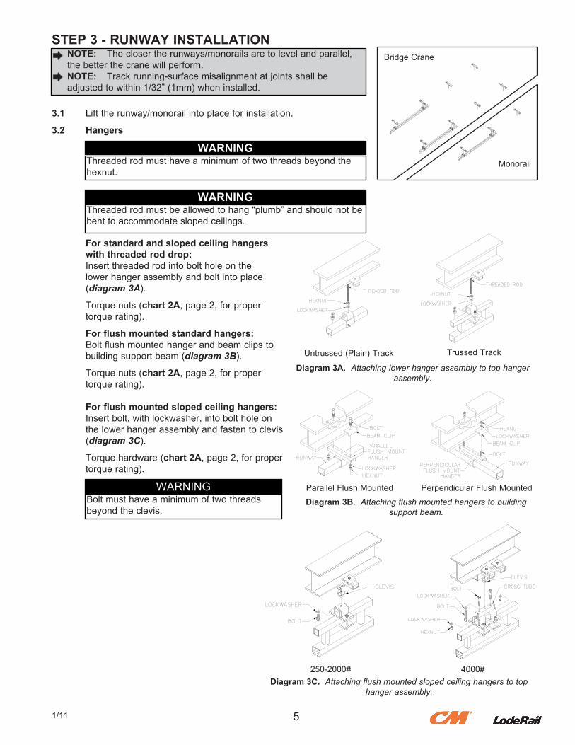
3.1. Lift.the.runway/monorail.into.place.for.installation.
3.2 Hangers
For standard and sloped ceiling hangers with threaded rod drop:. Insert.threaded.rod.into.bolt.hole.on.the. lower.hanger.assembly.and.bolt.into.place. (diagram 3A).
. Torque.nuts.(chart 2A,.page.2,.for.proper
. torque.rating).
For flush mounted standard hangers:. Bolt.flush.mounted.hanger.and.beam.clips.to. building.support.beam.(diagram 3B).
. Torque.nuts.(chart 2A,.page.2,.for.proper
. torque.rating).
For flush mounted sloped ceiling hangers:. Insert.bolt,.with.lockwasher,.into.bolt.hole.on. the.lower.hanger.assembly.and.fasten.to.clevis. (diagram 3C).
. Torque.hardware.(chart 2A,.page.2,.for.proper
. torque.rating).
51/11
.NOTE:. The.closer.the.runways/monorails.are.to.level.and.parallel,
.the.better.the.crane.will.perform.
.NOTE:. Track.running-surface.misalignment.at.joints.shall.be
.adjusted.to.within.1/32”.(1mm).when.installed.
WARNINGThreaded.rod.must.have.a.minimum.of.two.threads.beyond.the.hexnut.
WARNINGThreaded.rod.must.be.allowed.to.hang.“plumb”.and.should.not.be.bent.to.accommodate.sloped.ceilings.
Untrussed.(Plain).Track Trussed.Track
Diagram 3A. Attaching lower hanger assembly to top hanger assembly.
Parallel.Flush.Mounted Perpendicular.Flush.Mounted
Diagram 3B. Attaching flush mounted hangers to buildingsupport beam.
Bridge.Crane
Monorail
Diagram 3C. Attaching flush mounted sloped ceiling hangers to top hanger assembly.
WARNINGBolt.must.have.a.minimum.of.two.threads.beyond.the.clevis.
250-2000# 4000#
STEP 3 - RUNWAY INSTALLATION (CONTINUED)
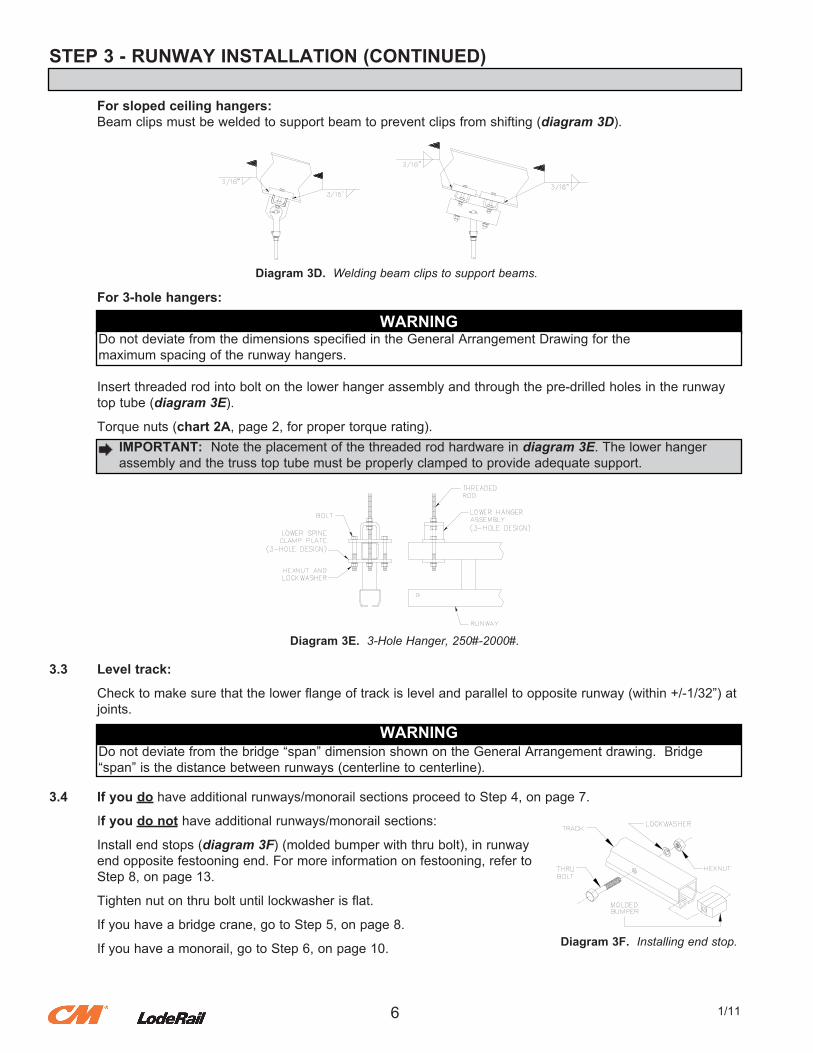
For sloped ceiling hangers:. Beam.clips.must.be.welded.to.support.beam.to.prevent.clips.from.shifting.(diagram 3D).
For 3-hole hangers:.
. Insert.threaded.rod.into.bolt.on.the.lower.hanger.assembly.and.through.the.pre-drilled.holes.in.the.runway
. top.tube.(diagram 3E).
. Torque.nuts.(chart 2A,.page.2,.for.proper.torque.rating).
3.3 Level track:
. Check.to.make.sure.that.the.lower.flange.of.track.is.level.and.parallel.to.opposite.runway.(within.+/-1/32”).at
. joints.
3.4 If you do.have.additional.runways/monorail.sections.proceed.to.Step.4,.on.page.7.
. If you do not have.additional.runways/monorail.sections:
. Install.end.stops.(diagram 3F).(molded.bumper.with.thru.bolt),.in.runway
. end.opposite.festooning.end..For.more.information.on.festooning,.refer.to
. Step.8,.on.page.13.
. Tighten.nut.on.thru.bolt.until.lockwasher.is.flat.
. If.you.have.a.bridge.crane,.go.to.Step.5,.on.page.8.
. If.you.have.a.monorail,.go.to.Step.6,.on.page.10.
6 1/11
Diagram 3D. Welding beam clips to support beams.
WARNINGDo.not.deviate.from.the.dimensions.specified.in.the.General.Arrangement.Drawing.for.themaximum.spacing.of.the.runway.hangers.
.IMPORTANT:. Note.the.placement.of.the.threaded.rod.hardware.in.diagram 3E..The.lower.hanger
.assembly.and.the.truss.top.tube.must.be.properly.clamped.to.provide.adequate.support.
Diagram 3E. 3-Hole Hanger, 250#-2000#.
WARNINGDo.not.deviate.from.the.bridge.“span”.dimension.shown.on.the.General.Arrangement.drawing...Bridge.“span”.is.the.distance.between.runways.(centerline.to.centerline).
Diagram 3F. Installing end stop.
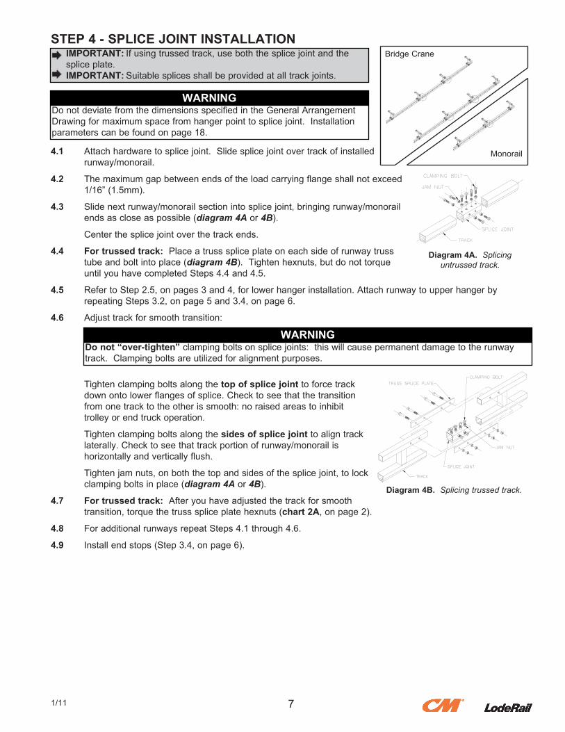
STEP 4 - SPLICE JOINT INSTALLATION
4.1. Attach.hardware.to.splice.joint...Slide.splice.joint.over.track.of.installed. runway/monorail.
4.2. The.maximum.gap.between.ends.of.the.load.carrying.flange.shall.not.exceed. 1/16”.(1.5mm).
4.3. Slide.next.runway/monorail.section.into.splice.joint,.bringing.runway/monorail. ends.as.close.as.possible.(diagram 4A.or.4B).
. Center.the.splice.joint.over.the.track.ends.
4.4 For trussed track:..Place.a.truss.splice.plate.on.each.side.of.runway.truss. tube.and.bolt.into.place.(diagram 4B)...Tighten.hexnuts,.but.do.not.torque. until.you.have.completed.Steps.4.4.and.4.5.
4.5. Refer.to.Step.2.5,.on.pages.3.and.4,.for.lower.hanger.installation..Attach.runway.to.upper.hanger.by. repeating.Steps.3.2,.on.page.5.and.3.4,.on.page.6.
4.6. Adjust.track.for.smooth.transition:
. Tighten.clamping.bolts.along.the top of splice joint.to.force.track
. down.onto.lower.flanges.of.splice..Check.to.see.that.the.transition
. from.one.track.to.the.other.is.smooth:.no.raised.areas.to.inhibit
. trolley.or.end.truck.operation.
. Tighten.clamping.bolts.along.the.sides of splice joint to.align.track
. laterally..Check.to.see.that.track.portion.of.runway/monorail.is
. horizontally.and.vertically.flush.
. Tighten.jam.nuts,.on.both.the.top.and.sides.of.the.splice.joint,.to.lock
. clamping.bolts.in.place.(diagram 4A.or.4B).
4.7. For trussed track:..After.you.have.adjusted.the.track.for.smooth. transition,.torque.the.truss.splice.plate.hexnuts.(chart 2A,.on.page.2).
4.8. For.additional.runways.repeat.Steps.4.1.through.4.6.
4.9. Install.end.stops.(Step.3.4,.on.page.6).
71/11
IMPORTANT:.If.using.trussed.track,.use.both.the.splice.joint.and.the.splice.plate. IMPORTANT:.Suitable.splices.shall.be.provided.at.all.track.joints.
WARNINGDo.not.deviate.from.the.dimensions.specified.in.the.General.Arrangement.Drawing.for.maximum.space.from.hanger.point.to.splice.joint...Installation.parameters.can.be.found.on.page.18.
Diagram 4A. Splicing untrussed track.
Do not “over-tighten” clamping.bolts.on.splice.joints:..this.will.cause.permanent.damage.to.the.runway.track...Clamping.bolts.are.utilized.for.alignment.purposes.
WARNING
Diagram 4B. Splicing trussed track.
Bridge.Crane
Monorail
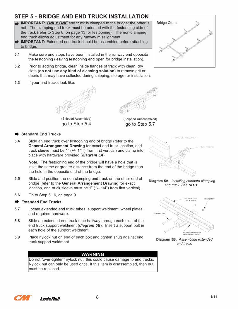
STEP 5 - BRIDGE AND END TRUCK INSTALLATION
5.1. Make.sure.end.stops.have.been.installed.in.the.runway.end.opposite. the.festooning.(leaving.festooning.end.open.for.bridge.installation).
5.2. Prior.to.adding.bridge,.clean.inside.flanges.of.track.with.clean,.dry. cloth.(do not use any kind of cleaning solution).to.remove.grit.or. debris.that.may.have.collected.during.shipping,.storage,.or.installation.
5.3. If.your.end.trucks.look.like:
Standard End Trucks
5.4. Slide.an.end.truck.over.festooning.end.of.bridge.(refer.to.the General Arrangement Drawing.for.exact.end.truck.location,.end. truck.sleeve.must.be.1”.(+/-.1/4”).from.first.vertical).and.clamp.into. place.with.hardware.provided.(diagram 5A).
. Note:..The.festooning.end.of.the.bridge.will.have.a.hole.that.is
. inset.the.same.or.greater.distance.from.the.end.of.the.bridge.than
. the.hole.in.the.opposite.end.of.the.bridge.
5.5. Slide.and.position.the.non-clamping.end.truck.on.the.other.end.of. bridge.(refer.to.the.General Arrangement Drawing for.exact. location,.end.truck.sleeve.must.be.1”.(+/-.1/4”).from.first.vertical).
5.6. Go.to.Step.5.16,.on.page.9.
Extended End Trucks
5.7. Locate.extended.end.truck.tubes,.support.weldment,.wheel.plates,. and.required.hardware.
5.8. Slide.an.extended.end.truck.tube.halfway.through.each.side.of.the. end.truck.support.weldment.(diagram 5B)...Insert.a.support.bolt.in. each.hole.of.the.support.weldment.
5.9. Place.nylock.nut.on.end.of.each.bolt.and.tighten.snug.against.end. truck.support.weldment.
8 1/11
.IMPORTANT: ONLY ONE.end.truck.is.clamped.to.the.bridge:.the.other.is
.not...The.clamping.end.truck.must.be.oriented.with.the.festooning.side.of. the.track.(refer.to.Step.8,.on.page.13.for.festooning)...The.non-clamping. end.truck.allows.adjustment.for.any.runway.misalignment.
.IMPORTANT:.Extended.end.truck.should.be.assembled.before.attaching
.to.bridge.
(Shipped.Assembled)
go.to.Step.5.4(Shipped.Unassembled)
go.to.Step.5.7
Diagram 5A. Installing standard clamping end truck. See NOTE.
Bridge.Crane
Diagram 5B. Assembling extended end truck.
WARNINGDo.not.“over-tighten”.nylock.nut;.this.could.cause.damage.to.end.trucks...Nylock.nut.can.only.be.used.once..If.this.item.is.disassembled,.then.nut.must.be.replaced.
SUPPORT.BOLT
EXTENDED.END.TRUCK.TUBES
EXTENDED.END.TRUCK.SUPPORT.WELDMENT
NYLOCK.NUT
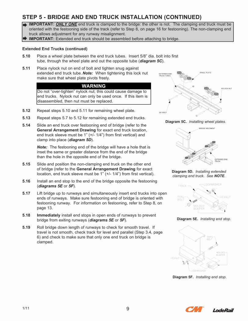
STEP 5 - BRIDGE AND END TRUCK INSTALLATION (CONTINUED)
Extended End Trucks (continued)
5.10. Place.a.wheel.plate.between.the.end.truck.tubes...Insert.5/8”.dia..bolt.into.first. tube,.through.the.wheel.plate.and.out.the.opposite.tube.(diagram 5C).
5.11. Place.nylock.nut.on.end.of.bolt.and.tighten.snug.against. extended.end.truck.tube..Note:..When.tightening.this.lock.nut. make.sure.that.wheel.plate.pivots.freely.
5.12. Repeat.steps.5.10.and.5.11.for.remaining.wheel.plate.
5.13. Repeat.steps.5.7.to.5.12.for.remaining.extended.end.trucks.
5.14. Slide.an.end.truck.over.festooning.end.of.bridge.(refer.to.the. General Arrangement Drawing.for.exact.end.truck.location,. end.truck.sleeve.must.be.1”.(+/-.1/4”).from.first.vertical).and. clamp.into.place.(diagram 5D).
. Note:..The.festooning.end.of.the.bridge.will.have.a.hole.that.is
. inset.the.same.or.greater.distance.from.the.end.of.the.bridge
. than.the.hole.in.the.opposite.end.of.the.bridge.
5.15. Slide.and.position.the.non-clamping.end.truck.on.the.other.end. of.bridge.(refer.to.the.General Arrangement Drawing.for.exact. location,.end.truck.sleeve.must.be.1”.(+/-.1/4”).from.first.vertical).
5.16. Install.an.end.stop.to.the.end.of.the.bridge.opposite.the.festooning. (diagrams 5E.or.5F).
5.17. Lift.bridge.up.to.runways.and.simultaneously.insert.end.trucks.into.open. ends.of.runways...Make.sure.festooning.end.of.bridge.is.oriented.with. festooning.runway...For.information.on.festooning,.refer.to.Step.8,.on. page.13.
5.18. Immediately.install.end.stops.in.open.ends.of.runways.to.prevent. bridge.from.exiting.runways.(diagrams 5E.or.5F).
5.19. Roll.bridge.down.length.of.runways.to.check.for.smooth.travel...If. travel.is.not.smooth,.check.track.for.level.and.parallel.(Step.3.4,.page. 6).and.check.to.make.sure.that.only.one.end.truck.on.bridge.is. clamped.
91/11
.IMPORTANT: ONLY ONE.end.truck.is.clamped.to.the.bridge:.the.other.is.not...The.clamping.end.truck.must.be
.oriented.with.the.festooning.side.of.the.track.(refer.to.Step.8,.on.page.16.for.festooning)..The.non-clamping.end. truck.allows.adjustment.for.any.runway.misalignment.
.IMPORTANT:.Extended.end.truck.should.be.assembled.before.attaching.to.bridge.
Diagram 5D. Installing extended clamping end truck. See NOTE.
Diagram 5C. Installing wheel plates.
WARNINGDo.not.“over-tighten”.nylock.nut;.this.could.cause.damage.to.end.trucks...Nylock.nut.can.only.be.used.once...If.this.item.is.disassembled,.then.nut.must.be.replaced.
Diagram 5E. Installing end stop.
Diagram 5F. Installing end stop.
WHEEL.PLATE
NYLOCK.NUT
5/8”.BOLT
EXTENDED.END.TRUCK.TUBES
BRIDGE.WELDMENT
EXTENDED.END.TRUCK
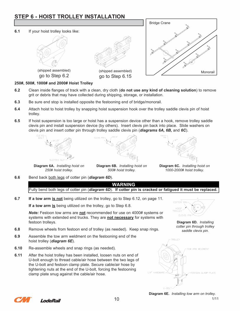
STEP 6 - HOIST TROLLEY INSTALLATION
6.1. If.your.hoist.trolley.looks.like:
250#, 500#, 1000# and 2000# Hoist Trolley
6.2. Clean.inside.flanges.of.track.with.a.clean,.dry.cloth.(do not use any kind of cleaning solution).to.remove. grit.or.debris.that.may.have.collected.during.shipping,.storage,.or.installation.
6.3. Be.sure.end.stop.is.installed.opposite.the.festooning.end.of.bridge/monorail.
6.4. Attach.hoist.to.hoist.trolley.by.snapping.hoist.suspension.hook.over.the.trolley.saddle.clevis.pin.of.hoist. trolley.
6.5. If.hoist.suspension.is.too.large.or.hoist.has.a.suspension.device.other.than.a.hook,.remove.trolley.saddle. clevis.pin.and.install.suspension.device.(by.others)...Insert.clevis.pin.back.into.place...Slide.washers.on. clevis.pin.and.insert.cotter.pin.through.trolley.saddle.clevis.pin.(diagrams 6A, 6B, and 6C).
6.6. Bend.back.both.legs.of.cotter.pin.(diagram 6D).
6.7 If a tow arm is not.being.utilized.on.the.trolley,.go.to.Step.6.12,.on.page.11.
. If a tow arm is.being.utilized.on.the.trolley,.go.to.Step.6.8.
. Note:.Festoon.tow.arms.are.not.recommended.for.use.on.4000#.systems.or
. systems.with.extended.end.trucks..They.are.not necessary.for.systems.with
. festoon.trolleys.
6.8. Remove.wheels.from.festoon.end.of.trolley.(as.needed)...Keep.snap.rings.
6.9. Assemble.the.tow.arm.weldment.on.the.festooning.end.of.the. hoist.trolley.(diagram 6E).
6.10. Re-assemble.wheels.and.snap.rings.(as.needed).
6.11. After.the.hoist.trolley.has.been.installed,.loosen.nuts.on.end.of. U-bolt.enough.to.thread.cable/air.hose.between.the.two.legs.of. the.U-bolt.and.festoon.clamp.plate..Secure.cable/air.hose.by. tightening.nuts.at.the.end.of.the.U-bolt,.forcing.the.festooning. clamp.plate.snug.against.the.cable/air.hose.
10 1/11
(shipped.assembled)go.to.Step.6.2
(shipped.assembled)go.to.Step.6.15
Bridge.Crane
Monorail
Diagram 6A. Installing hoist on 250# hoist trolley.
Diagram 6B. Installing hoist on 500# hoist trolley.
Diagram 6C. Installing hoist on 1000-2000# hoist trolley.
WARNINGFully.bend.both.legs.of.cotter.pin.(diagram 6D). If cotter pin is cracked or fatigued it must be replaced.
Diagram 6D. Installingcotter pin through trolley
saddle clevis pin.
Diagram 6E. Installing tow arm on trolley.
STEP 6 - HOIST TROLLEY INSTALLATION (CONTINUED)
6.12. Roll.hoist.trolley.into.open.end.of.track.on.bridge/monorail.
6.13. Install.end.stop.on.the.festooning.end.of.bridge/monorail.(diagram 3F,.on.page.6).
6.14. If.you.have.tagline,.go.to.Step.9,.on.page.15.
. If.you.do not.have.festooning,.go.to.Step.11,.on.page.17.
. If.you.do not.have.a.festoon.stack.section,.go.to.Step.8,.on.page.13.
. Otherwise.go.to.Step.7,.on.page.12.
Loadbar Hoist Trolley.4000#
6.15. Clean.inside.flanges.of.track.with.a.clean,.dry.cloth.(do not use any kind of cleaning solution).to.remove.grit.or.debris.that.may.have.collected.during. shipping,.storage,.or.installation.
6.16. Be.sure.end.stop.is.installed.opposite.the.festooning.end.of.bridge/monorail.
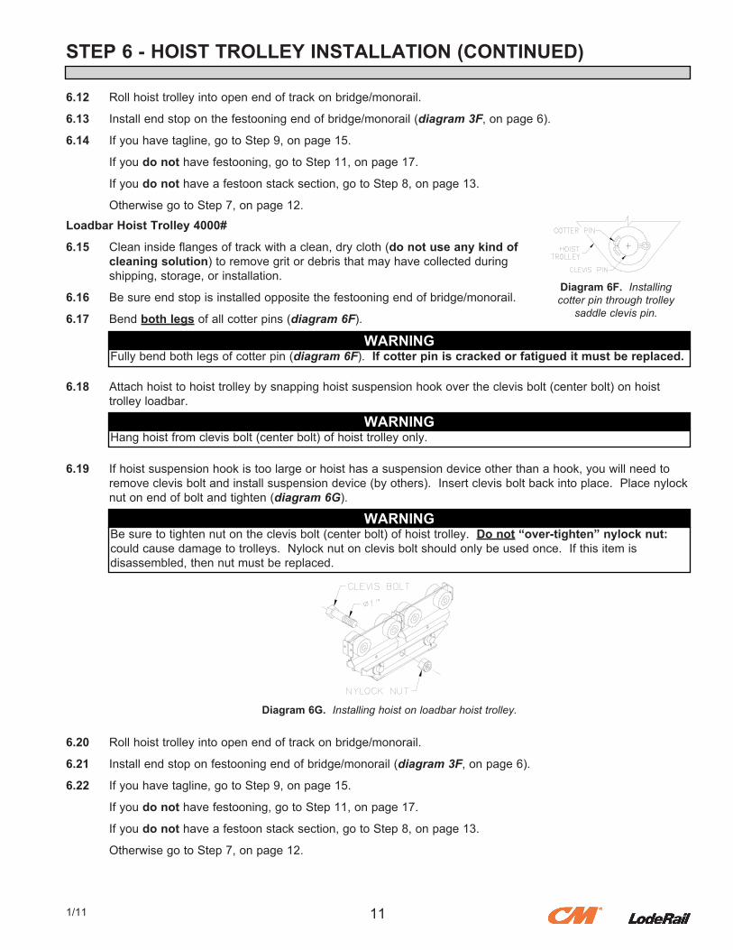
6.17. Bend.both legs.of.all.cotter.pins.(diagram 6F).
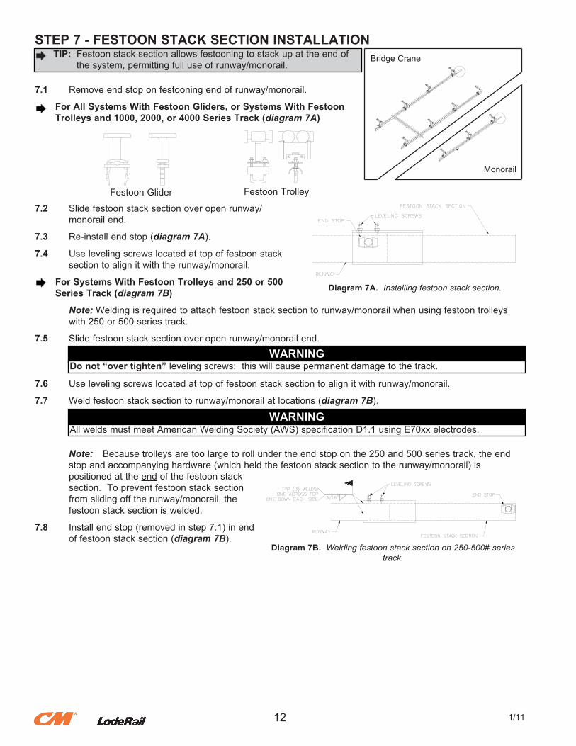
6.18. Attach.hoist.to.hoist.trolley.by.snapping.hoist.suspension.hook.over.the.clevis.bolt.(center.bolt).on.hoist. trolley.loadbar.
6.19. If.hoist.suspension.hook.is.too.large.or.hoist.has.a.suspension.device.other.than.a.hook,.you.will.need.to. remove.clevis.bolt.and.install.suspension.device.(by.others)...Insert.clevis.bolt.back.into.place...Place.nylock. nut.on.end.of.bolt.and.tighten.(diagram 6G).
6.20. Roll.hoist.trolley.into.open.end.of.track.on.bridge/monorail.
6.21. Install.end.stop.on.festooning.end.of.bridge/monorail.(diagram 3F,.on.page.6).
6.22. If.you.have.tagline,.go.to.Step.9,.on.page.15.
. If.you.do not.have.festooning,.go.to.Step.11,.on.page.17.
. If.you.do not.have.a.festoon.stack.section,.go.to.Step.8,.on.page.13.
. Otherwise.go.to.Step.7,.on.page.12.
111/11
Diagram 6F. Installingcotter pin through trolley
saddle clevis pin.
WARNINGFully.bend.both.legs.of.cotter.pin.(diagram 6F). If cotter pin is cracked or fatigued it must be replaced.
WARNINGHang.hoist.from.clevis.bolt.(center.bolt).of.hoist.trolley.only.
WARNINGBe.sure.to.tighten.nut.on.the.clevis.bolt.(center.bolt).of.hoist.trolley...Do not “over-tighten” nylock nut: .could.cause.damage.to.trolleys...Nylock.nut.on.clevis.bolt.should.only.be.used.once...If.this.item.isdisassembled,.then.nut.must.be.replaced.
Diagram 6G. Installing hoist on loadbar hoist trolley.
STEP 7 - FESTOON STACK SECTION INSTALLATION
7.1. Remove.end.stop.on.festooning.end.of.runway/monorail.
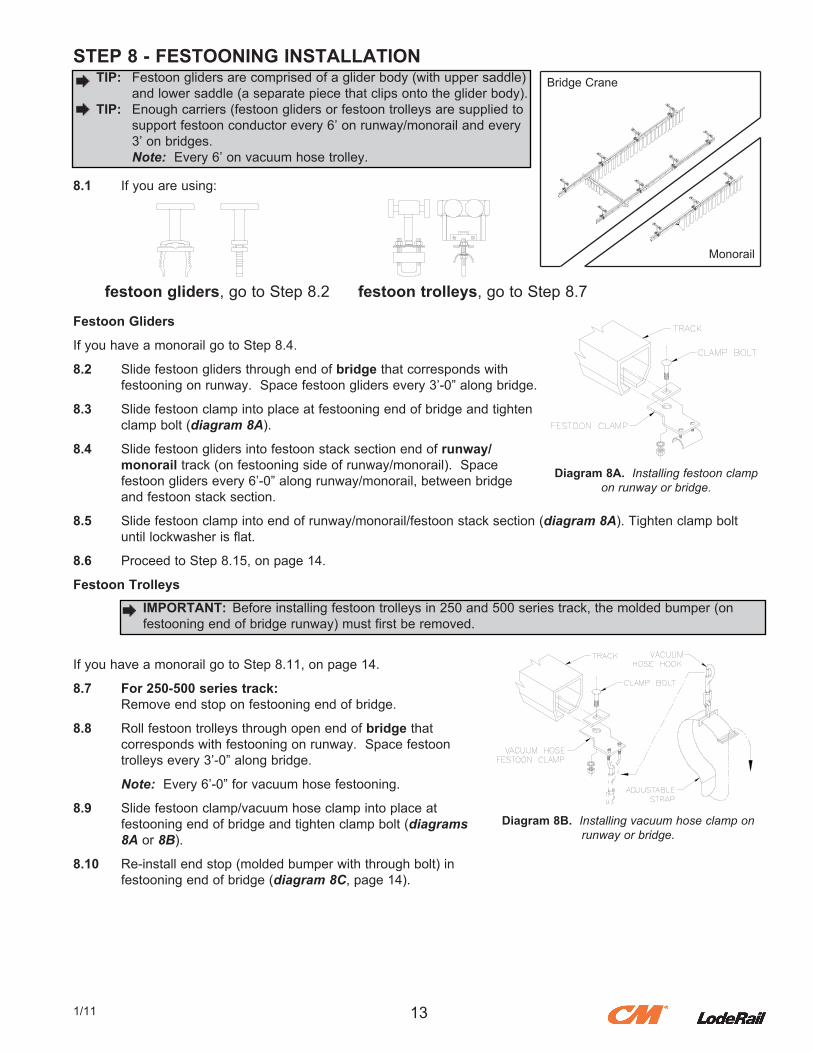
. For All Systems With Festoon Gliders, or Systems With Festoon Trolleys and 1000, 2000, or 4000 Series Track (diagram 7A)
7.2. Slide.festoon.stack.section.over.open.runway/. monorail.end.
7.3. Re-install.end.stop.(diagram 7A).
7.4. Use.leveling.screws.located.at.top.of.festoon.stack. section.to.align.it.with.the.runway/monorail.
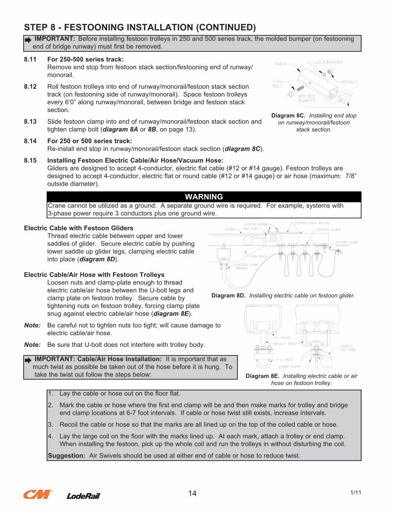
. For Systems With Festoon Trolleys and 250 or 500 Series Track (diagram 7B)
. Note:.Welding.is.required.to.attach.festoon.stack.section.to.runway/monorail.when.using.festoon.trolleys
. with.250.or.500.series.track.
7.5. Slide.festoon.stack.section.over.open.runway/monorail.end.
7.6. Use.leveling.screws.located.at.top.of.festoon.stack.section.to.align.it.with.runway/monorail.
7.7. Weld.festoon.stack.section.to.runway/monorail.at.locations.(diagram 7B).
. Note:. Because.trolleys.are.too.large.to.roll.under.the.end.stop.on.the.250.and.500.series.track,.the.end
. stop.and.accompanying.hardware.(which.held.the.festoon.stack.section.to.the.runway/monorail).is
. positioned.at.the.end.of.the.festoon.stack
. section...To.prevent.festoon.stack.section
. from.sliding.off.the.runway/monorail,.the
. festoon.stack.section.is.welded.
7.8. Install.end.stop.(removed.in.step.7.1).in.end. of.festoon.stack.section.(diagram 7B).
12 1/11
..TIP:. Festoon.stack.section.allows.festooning.to.stack.up.at.the.end.of
. the.system,.permitting.full.use.of.runway/monorail.
Festoon.Glider Festoon.Trolley
Diagram 7A. Installing festoon stack section.
WARNINGDo not “over tighten”.leveling.screws:..this.will.cause.permanent.damage.to.the.track.
WARNINGAll.welds.must.meet.American.Welding.Society.(AWS).specification.D1.1.using.E70xx.electrodes.
Diagram 7B. Welding festoon stack section on 250-500# series track.
Bridge.Crane
Monorail
STEP 8 - FESTOONING INSTALLATION
8.1. If.you.are.using:
Festoon Gliders
If.you.have.a.monorail.go.to.Step.8.4.
8.2. Slide.festoon.gliders.through.end.of.bridge.that.corresponds.with. festooning.on.runway...Space.festoon.gliders.every.3’-0”.along.bridge.
8.3. Slide.festoon.clamp.into.place.at.festooning.end.of.bridge.and.tighten. clamp.bolt.(diagram 8A).
8.4. Slide.festoon.gliders.into.festoon.stack.section.end.of.runway/ monorail.track.(on.festooning.side.of.runway/monorail)...Space. festoon.gliders.every.6’-0”.along.runway/monorail,.between.bridge. and.festoon.stack.section.
8.5. Slide.festoon.clamp.into.end.of.runway/monorail/festoon.stack.section.(diagram 8A)..Tighten.clamp.bolt. until.lockwasher.is.flat.
8.6. Proceed.to.Step.8.15,.on.page.14.
Festoon Trolleys
If.you.have.a.monorail.go.to.Step.8.11,.on.page.14.
8.7. For 250-500 series track:. Remove.end.stop.on.festooning.end.of.bridge.
8.8. Roll.festoon.trolleys.through.open.end.of.bridge.that. corresponds.with.festooning.on.runway...Space.festoon. trolleys.every.3’-0”.along.bridge.
. Note:..Every.6’-0”.for.vacuum.hose.festooning.
8.9. Slide.festoon.clamp/vacuum.hose.clamp.into.place.at. festooning.end.of.bridge.and.tighten.clamp.bolt.(diagrams 8A.or.8B).
8.10. Re-install.end.stop.(molded.bumper.with.through.bolt).in. festooning.end.of.bridge.(diagram 8C,.page.14).
131/11
festoon gliders,.go.to.Step.8.2 festoon trolleys,.go.to.Step.8.7
Diagram 8A. Installing festoon clamp on runway or bridge.
Bridge.Crane TIP:. Festoon.gliders.are.comprised.of.a.glider.body.(with.upper.saddle). and.lower.saddle.(a.separate.piece.that.clips.onto.the.glider.body)..TIP:. Enough.carriers.(festoon.gliders.or.festoon.trolleys.are.supplied.to. support.festoon.conductor.every.6’.on.runway/monorail.and.every
. 3’.on.bridges.
. Note:..Every.6’.on.vacuum.hose.trolley.
Monorail
IMPORTANT:. Before.installing.festoon.trolleys.in.250.and.500.series.track,.the.molded.bumper.(on. festooning.end.of.bridge.runway).must.first.be.removed.
Diagram 8B. Installing vacuum hose clamp on runway or bridge.
STEP 8 - FESTOONING INSTALLATION (CONTINUED)
8.11 For 250-500 series track:. Remove.end.stop.from.festoon.stack.section/festooning.end.of.runway/. monorail.
8.12. Roll.festoon.trolleys.into.end.of.runway/monorail/festoon.stack.section. track.(on.festooning.side.of.runway/monorail)...Space.festoon.trolleys. every.6’0”.along.runway/monorail,.between.bridge.and.festoon.stack. section.
8.13. Slide.festoon.clamp.into.end.of.runway/monorail/festoon.stack.section.and. tighten.clamp.bolt.(diagram 8A.or.8B,.on.page.13).
8.14 For 250 or 500 series track:. Re-install.end.stop.in.runway/monorail/festoon.stack.section.(diagram 8C).
8.15 Installing Festoon Electric Cable/Air Hose/Vacuum Hose:. Gliders.are.designed.to.accept.4-conductor,.electric.flat.cable.(#12.or.#14.gauge)..Festoon.trolleys.are. designed.to.accept.4-conductor,.electric.flat.or.round.cable.(#12.or.#14.gauge).or.air.hose.(maximum:..7/8”. outside.diameter).
Electric Cable with Festoon Gliders. Thread.electric.cable.between.upper.and.lower. saddles.of.glider...Secure.electric.cable.by.pushing. lower.saddle.up.glider.legs,.clamping.electric.cable. into.place.(diagram 8D).
Electric Cable/Air Hose with Festoon Trolleys. Loosen.nuts.and.clamp-plate.enough.to.thread. electric.cable/air.hose.between.the.U-bolt.legs.and. clamp.plate.on.festoon.trolley...Secure.cable.by. tightening.nuts.on.festoon.trolley,.forcing.clamp.plate. snug.against.electric.cable/air.hose.(diagram 8E).
Note:. Be.careful.not.to.tighten.nuts.too.tight;.will.cause.damage.to. electric.cable/air.hose.
Note:. Be.sure.that.U-bolt.does.not.interfere.with.trolley.body.
14 1/11
IMPORTANT:. Before.installing.festoon.trolleys.in.250.and.500.series.track,.the.molded.bumper.(on.festooning.end.of.bridge.runway).must.first.be.removed.
Diagram 8C. Installing end stop on runway/monorail/festoon
stack section.
WARNINGCrane.cannot.be.utilized.as.a.ground:..A.separate.ground.wire.is.required...For.example,.systems.with3-phase.power.require.3.conductors.plus.one.ground.wire.
Diagram 8D. Installing electric cable on festoon glider.
Diagram 8E. Installing electric cable or air hose on festoon trolley.
IMPORTANT: Cable/Air Hose Installation:..It.is.important.that.as.much.twist.as.possible.be.taken.out.of.the.hose.before.it.is.hung...To
. take.the.twist.out.follow.the.steps.below:
1.. Lay.the.cable.or.hose.out.on.the.floor.flat.
2.. Mark.the.cable.or.hose.where.the.first.end.clamp.will.be.and.then.make.marks.for.trolley.and.bridge. end.clamp.locations.at.6-7.foot.intervals...If.cable.or.hose.twist.still.exists,.increase.intervals.
3.. Recoil.the.cable.or.hose.so.that.the.marks.are.all.lined.up.on.the.top.of.the.coiled.cable.or.hose.
4.. Lay.the.large.coil.on.the.floor.with.the.marks.lined.up...At.each.mark,.attach.a.trolley.or.end.clamp... When.installing.the.festoon,.pick.up.the.whole.coil.and.run.the.trolleys.in.without.disturbing.the.coil.
Suggestion:..Air.Swivels.should.be.used.at.either.end.of.cable.or.hose.to.reduce.twist.
STEP 8 - FESTOONING INSTALLATION (CONTINUED)
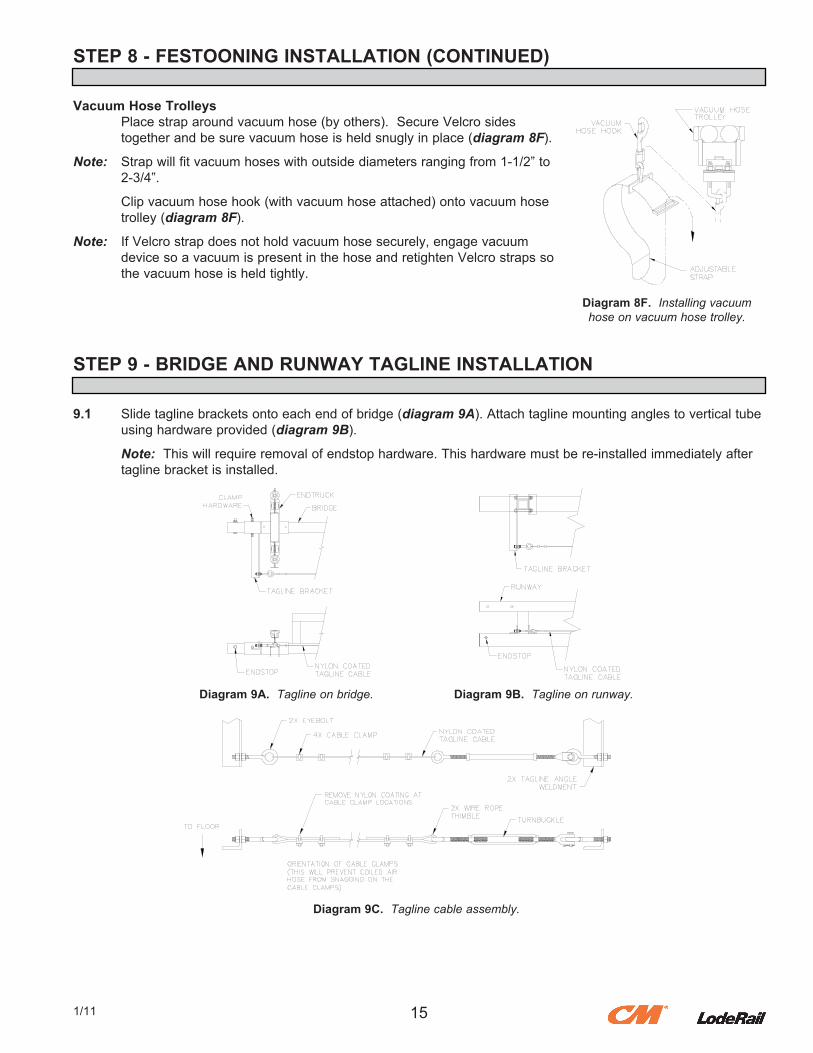
Vacuum Hose Trolleys. Place.strap.around.vacuum.hose.(by.others)...Secure.Velcro.sides. together.and.be.sure.vacuum.hose.is.held.snugly.in.place.(diagram 8F).
Note:. Strap.will.fit.vacuum.hoses.with.outside.diameters.ranging.from.1-1/2”.to. 2-3/4”.
. Clip.vacuum.hose.hook.(with.vacuum.hose.attached).onto.vacuum.hose
. trolley.(diagram 8F).
Note:. If.Velcro.strap.does.not.hold.vacuum.hose.securely,.engage.vacuum. device.so.a.vacuum.is.present.in.the.hose.and.retighten.Velcro.straps.so. the.vacuum.hose.is.held.tightly.
STEP 9 - BRIDGE AND RUNWAY TAGLINE INSTALLATION
9.1. Slide.tagline.brackets.onto.each.end.of.bridge.(diagram 9A)..Attach.tagline.mounting.angles.to.vertical.tube. using.hardware.provided.(diagram 9B).
. Note:..This.will.require.removal.of.endstop.hardware..This.hardware.must.be.re-installed.immediately.after
. tagline.bracket.is.installed.
151/11
Diagram 8F. Installing vacuum hose on vacuum hose trolley.
Diagram 9A. Tagline on bridge. Diagram 9B. Tagline on runway.
Diagram 9C. Tagline cable assembly.
STEP 9 - BRIDGE AND RUNWAY TAGLINE INSTALLATION (CONTINUED)
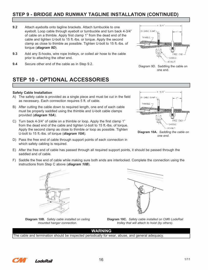
9.2. Attach.eyebolts.onto.tagline.brackets..Attach.turnbuckle.to.one. eyebolt..Loop.cable.through.eyebolt.or.turnbuckle.and.turn.back.4-3/4”. of.cable.on.a.thimble..Apply.first.clamp.1”.from.the.dead.end.of.the. cable.and.tighten.U-bolt.to.15.ft.-lbs..or.torque..Apply.the.second. clamp.as.close.to.thimble.as.possible..Tighten.U-bolt.to.15.ft.-lbs..of. torque.(diagram 9D).
9.3. Add.any.S-hooks,.wire.rope.trolleys,.or.coiled.air.hose.to.the.cable. prior.to.attaching.the.other.end.
9.4. Secure.other.end.of.the.cable.as.in.Step.9.2.
STEP 10 - OPTIONAL ACCESSORIES
Safety Cable InstallationA). The.safety.cable.is.provided.as.a.single.piece.and.must.be.cut.in.the.field. as.necessary..Each.connection.requires.5.ft..of.cable.
B). After.cutting.the.cable.down.to.required.length,.one.end.of.each.cable. must.be.properly.saddled.using.the.thimble.and.U-bolt.cable.clamps. provided.(diagram 10A).
C). Turn.back.4-3/4”.of.cable.on.a.thimble.or.loop..Apply.the.first.clamp.1”. from.the.dead.end.of.the.cable.and.tighten.U-bolt.to.15.ft.-lbs..of.torque.. Apply.the.second.clamp.as.close.to.thimble.or.loop.as.possible..Tighten. U-bolt.to.15.ft.-lbs..of.torque.(diagram 10A).
D). Pass.the.free.end.of.cable.through.support.points.of.each.connection.in. which.safety.cabling.is.required.
E). After.the.free.end.of.cable.has.passed.through.all.required.support.points,.it.should.be.passed.through.the. saddled.end.of.cable.
F). Saddle.the.free.end.of.cable.while.making.sure.both.ends.are.interlocked..Complete.the.connection.using.the. instructions.from.Step.C.above.(diagram 10B).
16 1/11
Diagram.9D...Saddling.the.cable.on.one.end.
Diagram 10B. Safety cable installed on ceilingmounted hanger connection.
Diagram 10C. Safety cable installed on CM® LodeRailtrolley that will attach to hoist (by others).
WARNINGThe.cable.and.termination.should.be.inspected.periodically.for.wear,.abuse,.and.general.adequacy.
Diagram 10A. Saddling the cable on one end.
STEP 10 - OPTIONAL ACCESSORIES (CONTINUED)
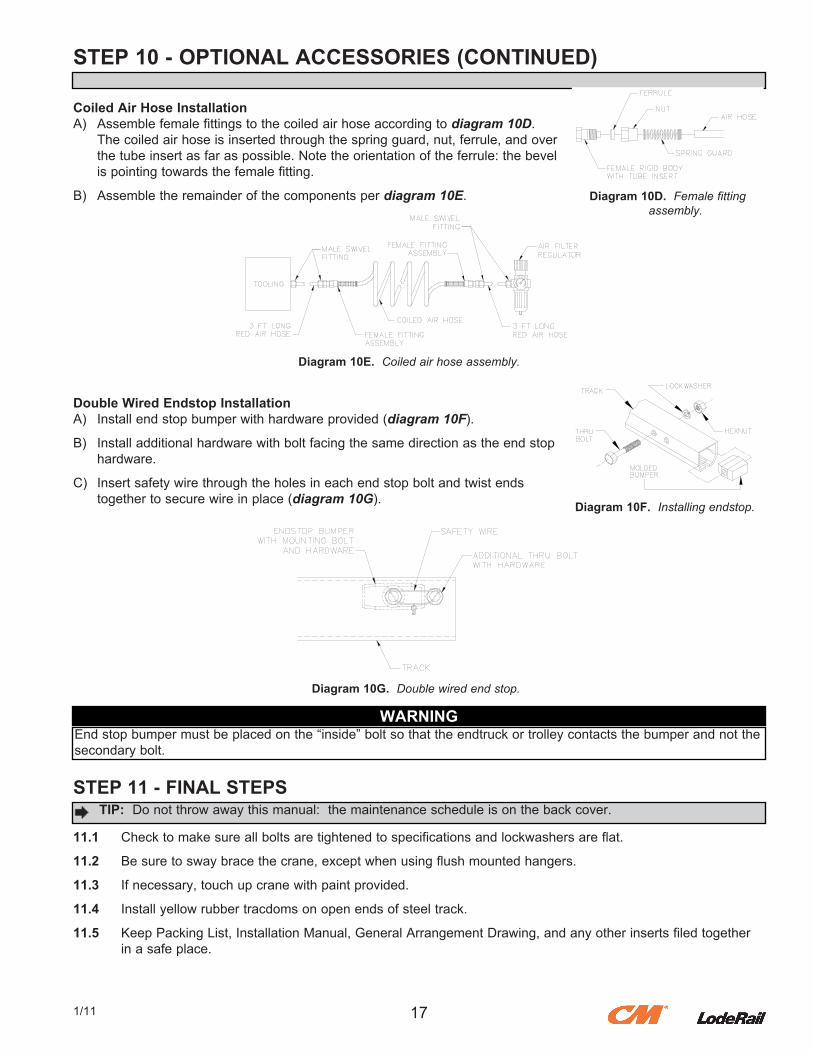
Coiled Air Hose InstallationA). Assemble.female.fittings.to.the.coiled.air.hose.according.to.diagram 10D.. The.coiled.air.hose.is.inserted.through.the.spring.guard,.nut,.ferrule,.and.over. the.tube.insert.as.far.as.possible..Note.the.orientation.of.the.ferrule:.the.bevel. is.pointing.towards.the.female.fitting.
B). Assemble.the.remainder.of.the.components.per.diagram 10E.
Double Wired Endstop InstallationA). Install.end.stop.bumper.with.hardware.provided.(diagram 10F).
B). Install.additional.hardware.with.bolt.facing.the.same.direction.as.the.end.stop. hardware.
C). Insert.safety.wire.through.the.holes.in.each.end.stop.bolt.and.twist.ends. together.to.secure.wire.in.place.(diagram 10G).
STEP 11 - FINAL STEPS
11.1. Check.to.make.sure.all.bolts.are.tightened.to.specifications.and.lockwashers.are.flat.
11.2. Be.sure.to.sway.brace.the.crane,.except.when.using.flush.mounted.hangers.
11.3. If.necessary,.touch.up.crane.with.paint.provided.
11.4. Install.yellow.rubber.tracdoms.on.open.ends.of.steel.track.
11.5. Keep.Packing.List,.Installation.Manual,.General.Arrangement.Drawing,.and.any.other.inserts.filed.together. in.a.safe.place.
171/11
Diagram 10F. Installing endstop.
Diagram 10G. Double wired end stop.
WARNINGEnd.stop.bumper.must.be.placed.on.the.“inside”.bolt.so.that.the.endtruck.or.trolley.contacts.the.bumper.and.not.the.secondary.bolt.
TIP: .Do.not.throw.away.this.manual:..the.maintenance.schedule.is.on.the.back.cover.
Diagram 10D. Female fitting assembly.
Diagram 10E. Coiled air hose assembly.
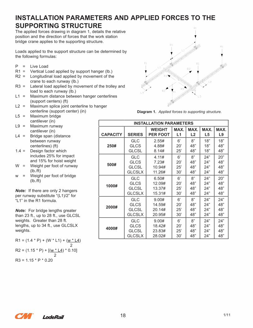
INSTALLATION PARAMETERS AND APPLIED FORCES TO THE SUPPORTING STRUCTUREThe.applied.forces.drawing.in.diagram.1,.details.the.relative.position.and.the.direction.of.forces.that.the.work.stationbridge.crane.applies.to.the.supporting.structure.
Loads.applied.to.the.support.structure.can.be.determined.by.the.following.formulas:
P. =. Live.LoadR1. =. Vertical.Load.applied.by.support.hanger.(lb.)R2. =. Longitudinal.load.applied.by.movement.of.the. . crane.to.each.runway.(lb.)R3. =. Lateral.load.applied.by.movement.of.the.trolley.and. . load.to.each.runway.(lb.)L1. =. Maximum.distance.between.hanger.centerlines. . (support.centers).(ft)L2. =. Maximum.splice.joint.centerline.to.hanger. . centerline.(support.center).(in)L5. =. Maximum.bridge. . cantilever.(in)L9. =. Maximum.runway. . cantilever.(in)L4. =. Bridge.span.(distance. . between.runway. . centerlines).(ft)1.4.=. Design.factor.which. . includes.25%.for.impact. . and.15%.for.hoist.weightW. =. Weight.per.foot.of.runway. . (lb./ft)w. =. Weight.per.foot.of.bridge. . (lb./ft)
Note:..If.there.are.only.2.hangersper.runway.substitute.“(L1)/2”.for“L1”.in.the.R1.formula.
Note:..For.bridge.lengths.greaterthan.23.ft.,.up.to.28.ft.,.use.GLCSLweights...Greater.than.28.ft.lengths,.up.to.34.ft.,.use.GLCSLXweights.
R1.=.(1.4.*.P).+.(W.*.L1).+.(w.*.L4). . . . ........2R2.=.(1.15.*.P).+.[(w.*.L4).*.0.10]. . . .......2R3.=.1.15.*.P.*.0.20
18 1/11
Diagram 1. Applied forces to supporting structure.
INSTALLATION PARAMETERS
CAPACITY SERIESWEIGHT
PER FOOTMAX.
L1MAX.
L2MAX.
L5MAX.
L9
250#GLCGLCSGLCSL
2.55#4.88#8.14#
6’20’25’
8”48”48”
18”18”18”
18”48”48”
500#
GLCGLCSGLCSLGLCSLX
4.11#7.23#10.94#11.26#
6’20’25’30’
8”48”48”48”
24”24”24”24”
20”48”48”48”
1000#
GLCGLCSGLCSLGLCSLX
6.50#12.09#13.37#15.31#
6’20’25’30’
8”48”48”48”
24”24”24”24”
20”48”48”48”
2000#
GLCGLCSGLCSLGLCSLX
9.00#14.59#20.14#20.95#
6’20’25’30’
8”48”48”48”
24”24”24”24”
24”48”48”48”
4000#
GLCGLCSGLCSLGLCSLX
9.00#18.42#23.83#28.02#
6’20’25’30’
8”48”48”48”
24”24”24”24”
24”48”48”48”
SWAY AND THRUST BRACING GUIDELINES
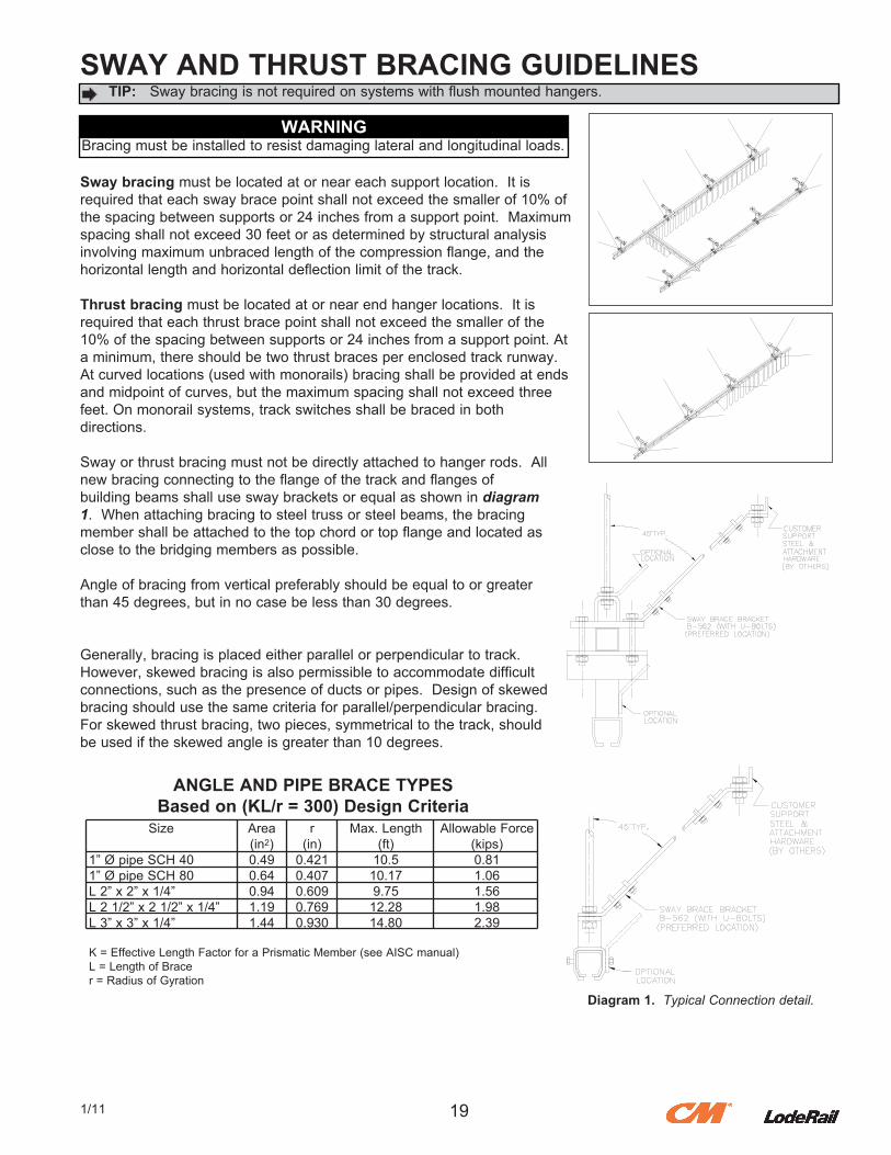
Sway bracing.must.be.located.at.or.near.each.support.location...It.is.required.that.each.sway.brace.point.shall.not.exceed.the.smaller.of.10%.of.the.spacing.between.supports.or.24.inches.from.a.support.point...Maximum.spacing.shall.not.exceed.30.feet.or.as.determined.by.structural.analysis.involving.maximum.unbraced.length.of.the.compression.flange,.and.thehorizontal.length.and.horizontal.deflection.limit.of.the.track.
Thrust bracing.must.be.located.at.or.near.end.hanger.locations...It.is.required.that.each.thrust.brace.point.shall.not.exceed.the.smaller.of.the.10%.of.the.spacing.between.supports.or.24.inches.from.a.support.point..At.a.minimum,.there.should.be.two.thrust.braces.per.enclosed.track.runway...At.curved.locations.(used.with.monorails).bracing.shall.be.provided.at.ends.and.midpoint.of.curves,.but.the.maximum.spacing.shall.not.exceed.three.feet..On.monorail.systems,.track.switches.shall.be.braced.in.bothdirections.
Sway.or.thrust.bracing.must.not.be.directly.attached.to.hanger.rods...All.new.bracing.connecting.to.the.flange.of.the.track.and.flanges.ofbuilding.beams.shall.use.sway.brackets.or.equal.as.shown.in.diagram 1...When.attaching.bracing.to.steel.truss.or.steel.beams,.the.bracing.member.shall.be.attached.to.the.top.chord.or.top.flange.and.located.as.close.to.the.bridging.members.as.possible.
Angle.of.bracing.from.vertical.preferably.should.be.equal.to.or.greater.than.45.degrees,.but.in.no.case.be.less.than.30.degrees.
Generally,.bracing.is.placed.either.parallel.or.perpendicular.to.track...However,.skewed.bracing.is.also.permissible.to.accommodate.difficult.connections,.such.as.the.presence.of.ducts.or.pipes...Design.of.skewed.bracing.should.use.the.same.criteria.for.parallel/perpendicular.bracing...For.skewed.thrust.bracing,.two.pieces,.symmetrical.to.the.track,.should.be.used.if.the.skewed.angle.is.greater.than.10.degrees.
191/11
TIP:. Sway.bracing.is.not.required.on.systems.with.flush.mounted.hangers.
WARNINGBracing.must.be.installed.to.resist.damaging.lateral.and.longitudinal.loads.
Diagram 1. Typical Connection detail.
K.=.Effective.Length.Factor.for.a.Prismatic.Member.(see.AISC.manual)L.=.Length.of.Bracer.=.Radius.of.Gyration
Size
1”.Ø.pipe.SCH.401”.Ø.pipe.SCH.80L.2”.x.2”.x.1/4”L.2.1/2”.x.2.1/2”.x.1/4”L.3”.x.3”.x.1/4”
Area.(in2)0.490.640.941.191.44
r(in)0.4210.4070.6090.7690.930
Max..Length.(ft)10.510.179.7512.2814.80
Allowable.Force.(kips)0.811.061.561.982.39
ANGLE AND PIPE BRACE TYPESBased on (KL/r = 300) Design Criteria
CRANE OPERATOR INSTRUCTIONSOverhead.cranes.and.jib.cranes.generally.handle.materials.over.working.areas.where.there.are.personnel...Therefore,.it.is.important.for.the.Crane.Operator.to.be.instructed.in.the.use.of.the.crane.and.to.understand.the.severe.consequences.of.careless.operation...It.is.not.intended.that.these.suggestions.take.precedence.over.existing.plant.safety.rules.and.regulations.or.OSHA.regulations...However,.a.thorough.study.of.the.following.information.should.provide.a.better.understanding.of.safe.operation.and.afford.a.greater.margin.of.safety.for.people.and.machinery.on.the.plant.floor...It.must.be.recognized.that.these.are.suggestions.for.the.Crane.Operator’s.use...It.is.the.responsibility.of.the.owner.to.make.personnel.aware.of.all.federal,.state.and.local.rules.and.codes,.and.to.make.certain.operators.are.properly.trained.
QualificationsCrane.operation,.to.be.safe.and.efficient,.requires.skill:..the.exercise.of.extreme.care.and.good.judgment,.alertness.and.concentration,.and.rigid.adherence.to.proven.safety.rules.and.practices.as.outlined.in.applicable.and.current.ANSI.and.OSHA.safety.standards...In.general.practice,.no.person.should.be.permitted.to.operate.a.crane:......•. Who.cannot.speak.the.appropriate.language.or.read.and.understand.the.printed.instructions.......•. Who.is.not.of.legal.age.to.operate.this.type.of.equipment.......•. Whose.hearing.or.eyesight.is.impaired.(unless.suitably.corrected.with.good.depth.perception).......•. Who.may.be.suffering.from.heart.or.other.ailments.which.might.interfere.with.the.operator’s.safe.performance.......•. Unless.the.operator.has.carefully.read.and.studied.this.operation.manual.......•. Unless.the.operator.has.been.properly.instructed.......•. Unless.the.operator.has.demonstrated.his.instructions.through.practical.operation.......•. Unless.the.operator.is.familiar.with.hitching.equipment.and.safe.hitching.equipment.practices.
Handling the Bridge Travel MotionBefore.using.the.bridge.of.the.crane,.the.operator.should.be.sure.the.hook.is.high.enough.to.clear.any.obstruction...Before.a.load.is.handled.by.the.crane,.the.bridge.should.be.brought.into.position.so.that.it.is.directly.over.the.load...Start.the.bridge.slowly.and.bring.it.up.to.speed.gradually...Approaching.the.place.where.it.is.desired.to.stop.the.bridge,.reduce.the.bridge.speed.
Handling the Trolley MotionBefore.a.load.is.handled,.the.hoist.should.be.positioned.directly.over.the.load.that.is.to.be.handled...When.the.slack.is.taken.out.of.the.slings,.if.the.hoist.is.not.directly.over.the.load,.bring.it.directly.over.the.load.before.hoisting.is.continued...Failure.to.center.the.hoist.over.the.load.may.cause.the.load.to.swing.upon.lifting...Always.start.the.trolley.motion.slowly.and.reduce.the.trolley.speed.gradually.
Handling the Hoist MotionRefer.to.the.lifting.(hoist).equipment’s.operating.instructions.
GENERAL SUGGESTIONSKnow Your CraneCrane.operators.should.be.familiar.with.the.principal.parts.of.a.crane.and.have.a.thorough.knowledge.of.crane.control.functions.and.movements...The.crane.operator.should.be.required.to.know.the.location.and.proper.operation.of.the.main.conductor.disconnecting.means.for.all.power.to.the.attachments.on.the.crane.
ResponsibilityEach.crane.operator.should.be.held.directly.responsible.for.the.safe.operation.of.the.crane...Whenever.there.is.any.doubt.as.to.SAFETY,.the.crane.operator.should.stop.the.crane.and.refuse.to.handle.loads.until:..(1).safety.has.been.assured.or.(2).the.operator.has.been.ordered.to.proceed.by.the.supervisor,.who.then.assumes.all.responsibility.for.the.SAFETY.of.the.lift.Do.not.permit.ANYONE.to.ride.on.the.hook.or.a.load.InspectionTest.the.crane.movement.and.any.attachments.on.the.crane.at.the.beginning.of.each.shift...Whenever.the.operator.finds.anything.wrong.or.apparently.wrong,.the.problem.should.be.reported.immediately.to.the.proper.supervisor.and.appropriate.corrective.action.taken.
Operating SuggestionsOne.measure.of.a.good.crane.operator.is.the.smoothness.of.the.crane.operation...The.good.crane.operator.should.know.and.follow.these.proven.suggestions.for.safe,.efficient.crane.handling.1.. The.crane.should.be.moved.smoothly.and.gradually.to.avoid.abrupt,.jerky.movements.of.the.load...Slack.must.be.removed.from.the.sling.and.hoisting.ropes. before.the.load.is.lifted.2.. Center.the.crane.over.the.load.before.starting.the.hoist.to.avoid.swinging.the.load.as.the.lift.is.started...Loads.should.not.be.swung.by.the.crane.to.reach.areas. not.under.the.crane.3.. Crane-hoisting.ropes.should.be.kept.vertical...Cranes.shall.not.be.used.for.side.pulls.4.. Be.sure.everyone.in.the.immediate.area.is.clear.of.the.load.and.aware.that.a.load.is.being.moved.5.. Do.not.make.lifts.beyond.the.rated.load.capacity.of.the.crane,.sling.chains,.rope.slings,.etc.6.. Make.certain.that.before.moving.the.load,.load.slings,.load.chains,.or.other.lifting.devices.are.fully.seated.in.the.saddle.of.the.hook.with.hook.latch.closed.(if. equipped.with.hook.latch).7.. Check.to.be.sure.that.the.load.and/or.bottom.block.is.lifted.high.enough.to.clear.all.obstructions.when.moving.boom.or.trolley.8.. At.no.time.should.a.load.be.left.suspended.from.the.crane.unless.the.operator.has.the.push.button.with.the.power.on,.and.under.this.condition.keep.the.load.as. close.as.possible.to.the.floor.to.minimize.the.possibility.of.an.injury.if.the.load.should.drop...When.the.crane.is.holding.a.load,.the.crane.operator.should.remain. at.the.push.button.9.. Do.not.lift.loads.with.sling.hooks.hanging.loose...If.all.sling.hooks.are.not.needed,.they.should.be.properly.stored,.or.use.a.different.sling.10.. All.slings.or.cables.should.be.removed.from.the.crane.hooks.when.not.in.use.(dangling.cables.or.hooks.hung.in.sling.rings.can.inadvertently.snag.other.objects. when.the.crane.is.moving).11.. Operators.shall.not.carry.loads.and/or.empty.bottom.blocks.over.personnel...Particular.additional.caution.should.be.practiced.when.using.magnet.or.vacuum. devices...Loads,.or.parts.of.loads,.held.magnetically.could.drop...Failure.of.power.to.magnets.or.vacuum.devices.can.result.in.dropping.the.load...Extra. precaution.should.be.exercised.when.handling.molten.metal.in.the.proximity.of.personnel.12.. Whenever.the.operator.leaves.the.crane.the.following.procedure.should.be.followed:. . •.....Raise.all.hooks.to.an.intermediate.position.. . •.....Spot.the.crane.at.an.approved.designated.location.. . •.....Place.all.controls.in.the.“off”.position.. . •.....Open.the.main.switch.to.the.“off”.position.. . •.....Make.visual.check.before.leaving.the.crane.13.. In.the.case.of.emergency.or.during.inspection,.repairing,.cleaning.or.lubrication,.a.warning.sign.or.signal.should.be.displayed.and.the.main.switch.should.be. locked.in.the.“off”.position...This.should.be.done.whether.the.work.is.being.done.by.the.crane.operator.or.by.others.14.. Contact.with.rotation.stops.or.trolley.end.stops.shall.be.made.with.extreme.caution...The.operator.should.do.so.with.particular.care.for.the.safety.or.persons. below.the.crane,.and.only.after.making.certain.that.any.persons.on.the.other.cranes.are.aware.of.what.is.being.done.15.. ANY.SAFETY.FEATURES.AND.MECHANISMS.BUILT-IN.OR.OTHERWISE.PROVIDED.WITH.THE.CRANE.BY.CM®.LODERAIL.ARE.REQUIRED.FOR.THE. SAFE.OPERATION.OF.THE.CRANE...DO.NOT,.UNDER.ANY.CIRCUMSTANCES,.REMOVE.OR.OTHERWISE.IMPAIR.OR.DISABLE.THE.PROPER. FUNCTIONING.OF.ANY.CRANE.SAFETY.MECHANISMS.OR.FEATURES.BUILT-IN.OR.OTHERWISE.PROVIDED.BY.CM®.LODERAIL.FOR.SAFE. OPERATION.OF.THE.CRANE..ANY.REMOVAL,.IMPAIRMENT.OR.DISABLING.OF.ANY.SUCH.SAFETY.MECHANISMS.OR.FEATURES.OR.OTHER.USE.OR. OPERATION.OF.THE.CRANE.WITHOUT.THE.COMPLETE.AND.PROPER.FUNCTIONING.OF.ANY.SUCH.SAFETY.MECHANISMS.OR.FEATURES. AUTOMATICALLY.AND.IMMEDIATELY.VOIDS.ANY.AND.ALL.EXPRESS.AND.IMPLIED.WARRANTIES.OF.ANY.KIND.OR.NATURE.
20 1/11
LIMITED WARRANTYIt.is.agreed.that.the.equipment.purchased.hereunder.is.subject.to.the.following.LIMITED.warranty.and.no.other..Columbus.McKinnon.Corporation.(“CM®.LodeRail”)warrants.the.manual.push-pull.Work.Station.Cranes.and.Jib.Crane.products.to.be.free.from.defects.in.material.or.workmanship.for.a.period.of..five..years.or.10,000.hours.use.from.date.of.shipment..CM®.LodeRail.warrants.the.Motorized.Work.Station.Crane.products.to.be.free.from.defects.in.material.or.workmanship.for.a.period.of.two.years.or.4,000.hours.use.from.the.date.of.shipment..This.warranty.shall.not.cover.failure.or.defective.operation.caused.by.operation.in.excess.of.recommended.capacities,.misuses,.negligence.or.accident,.and.alteration.or.repair.not.authorized.by.CM®.LodeRail..No.system.shall.be.modified.after.manufacture.without.thewritten.authorization.of.CM®.LodeRail..Any.field.modification.made.to.the.system.without.the.written.authorization.of.CM®.LodeRail.shall.void.CM®.LodeRail’s.warranty.obligation..OTHER.THAN.AS.SET.FORTH.HEREIN,.NO.OTHER.EXPRESS.WARRANTIES,.AND.NO.IMPLIED.WARRANTIES,.ORAL.OR.WRITTEN,.INCLUDING.BUT.NOT.LIMITED.TO.THE.WARRANTIES.OF.MERCHANTABILITY.OR.FITNESS.FOR.A.PARTICULAR.PURPOSE,.ARE.MADE.BY.CM®.LODERAIL.WITH.RESPECT.TO.ITS.PRODUCTS.AND.ALL.SUCH.WARRANTIES.ARE.HEREBY.SPECIFICALLY.DISCLAIMED..CM®.LODERAIL.SHALL.NOT.BE.LIABLE.UNDER.ANY.CIRCUMSTANCES.FOR.ANY.INCIDENTAL,.SPECIAL.AND/OR.CONSEQUENTIAL.DAMAGES.WHATSOEVER,.WHETHER.OR.NOT.FORESEEABLE,.INCLUDING.BUT.NOT.LIMITED.TO.DAMAGES.FOR.LOST.PROFITS.AND.ALL.SUCH.INCIDENTAL,.SPECIAL.AND/OR.CONSEQUENTIAL.DAMAGES.ARE.HEREBY.ALSO.SPECIFICALLY.DISCLAIMED..CM®.LodeRail’s.obligation.and.Purchaser’s.or.end.user’s.sole.remedy..under.this.warranty.is.limited.to.the.replacement.or.repair.of.CM®.LodeRail’s.products.at.the.factory,.or.at.the.discretion.of.CM®.LodeRail,.at.a.location.designated.by.CM®.LodeRail...Purchaser.or.end.user.shall.be.solely.responsible.for.all.freight.and.transportation.costs.incurred.in.connection.with.any.warranty.work.provided.by.CM®.LodeRail.hereunder...CM®.LodeRail.will.not.be.liable.for.any.loss,.injury.or.damage.to.persons.or.property,.nor.for.damages.of.any.kind.resulting.from.failure.or.defective.operation.of.any.materials.or.equipment.furnished.hereunder..Components.and.accessories.not.manufactured.by.CM®.LodeRail.are.not.included.in.this.warranty...Purchaser’s.or.end.user’s.remedy.for.components.and.accessories.not.manufactured.by.CM®.LodeRail.is.limited.to.and.determined.by.the.terms.and.conditions.of.the.warranty.provided.by.the.respective.manufacturers.of.such.components.and.accessories. A) DISCLAIMER OF IMPLIED WARRANTY OF MERCHANTABILITY. . . CM®.LodeRail.and.Purchaser.agree.that.the.implied.warranty.of.merchantability.is.excluded.from.this.transaction.and.shall.not.apply.to.the. . . goods.involved.in.this.transaction. B) DISCLAIMER OF IMPLIED WARRANTY OF FITNESS FOR PARTICULAR PURPOSE. . . CM®.LodeRail.and.Purchaser.agree.that.the.implied.warranty.of.fitness.for.particular.purpose.is.excluded.from.this.transaction.and.shall.not. . . apply.to.the.goods.involved.in.this.transaction. C) DISCLAIMER OF EXPRESS WARRANTY. . . CM®.LodeRail’s.agents,.or.dealer’s.agents,.or.distributor’s.agents.may.have.made.oral.statements.about.the.machinery.and.equipment. . . described.in.this.transaction..Such.statements.do.not.constitute.warranties,.and.Purchaser.agrees.not.to.rely.on.such.statements..Purchaser. . . also.agrees.that.such.statements.are.not.part.of.this.transaction. D) DISCLAIMER OF SPECIAL, INCIDENTAL AND CONSEQUENTIAL DAMAGES. . . CM®.LodeRail.and.Purchaser.agree.that.any.claim.made.by.Purchaser.which.is.inconsistent.with.CM®.LodeRail’s.obligations.and.the.warranty. . . remedies.provided.with.CM®.LodeRail’s.products,.and.in.particular,.special,.incidental.and.consequential.damages,.are.expressly.excluded. E) DEALER OR DISTRIBUTOR NOT AN AGENT. . . CM®.LodeRail.and.Purchaser.agree.that.Purchaser.has.been.put.on.notice.that.dealer.or.distributor.is.not.CM®.LodeRail’s.agent.in.any. . . respect.for.any.reason..CM®.LodeRail.and.Purchaser.also.agree.that.Purchaser.has.been.put.on.notice.that.dealer.or.distributor.is.not. . . authorized.to.incur.any.obligations.or.to.make.any.representations.or.warranties.on.CM®.LodeRail’s.behalf.other.than.those.specifically.set. . . forth.in.CM®.LodeRail’s.warranty.provided.in.connection.with.its.product. F) MERGER. . . This.warranty.agreement.constitutes.a.final.and.complete.written.expression.of.all.the.terms.and.conditions.of.this.warranty.and.is.a.complete. . . and.exclusive.statement.of.those.terms. G) PAINTING. . . Every.crane.(excluding.components).receives.a.quality.paint.job.before.leaving.the.factory..Unfortunately,.no.paint.will.protect.against.the. . . abuses.received.during.the.transportation.process.via.common.carrier..We.have.included.at.least.one.(1).twelve.ounce.spray.can.for.touchup. . . with.each.crane.ordered.(unless.special.paint.was.specified)..If.additional.paint.is.required,.contact.a.CM®.LodeRail.Customer.Service. . . Representative.at.1-800-888-0985.or.1-716-689-5400.
Title and Ownership:. Title.to.the.machinery.and.equipment.described.in.the.foregoing.proposal.shall.remain.with.CM®.LodeRail.and.shall.not.pass.to.the.Purchaser.until.the.full. amount.herein.agreed.to.be.paid.has.been.fully.paid.in.cash.
Claims and Damages:. Unless.expressly.stated.in.writing,.goods.and.equipment.shall.be.at.Purchaser’s.risk.on.and.after.Seller’s.delivery.in.good.shipping.order.to.the.Carrier..CM®. LodeRail.shall.in.no.event.be.held.responsible.for.materials.furnished.or.work.performed.by.any.person.other.than.it.or.its.authorized.representative.or.agent.
Cancellations:. If.it.becomes.necessary.for.the.purchaser.to.cancel.this.order.wholly.or.in.part,.he.shall.at.once.so.advise.CM®.LodeRail.in.writing..Upon.receipt.of.such.written. notice.all.work.will.stop.immediately..If.the.order.entails.only.stock.items,.a.flat.restocking.charge.of.15%.of.the.purchase.price.will.become.due.and.payable.by. Purchaser.to.CM®.LodeRail..Items.purchased.specifically.for.the.canceled.order.shall.be.charged.for.in.accordance.with.the.cancellation.charges.of.our.supplier. plus.15%.for.handling.in.our.factory..The.cost.of.material.and/or.labor.expended.in.general.fabrication.for.the.order.shall.be.charged.for.on.the.basis.of.total. costs.to.CM®.LodeRail.up.to.the.time.of.cancellation.plus.15%.
Returns:. No.equipment,.materials.or.parts.may.be.returned.to.CM®.LodeRail.without.express.permission.in.writing.to.do.so.
. Extra.Charge.Delay:.If.Purchaser.delays.or.interrupts.progress.of.Seller’s.performance,.or.causes.changes.to.be.made,.Purchaser.agrees.to.reimburse.CM®
. LodeRail.for.expense,.if.any,.incident.to.such.delay.
Changes and Alterations:. CM®.LodeRail.reserves.the.right.to.make.changes.in.the.details.of.construction.of.the.equipment,.as.in.its.judgment,.will.be.in.the.interest.of.the.Purchaser;.will. make.any.changes.in.or.additions.to.the.equipment.which.may.be.agreed.upon.in.writing.by.the.Purchaser;.and.CM®.LodeRail.is.not.obligated.to.make.such. changes.in.products.previously.sold.any.customer.
Third Party Action:. Should.CM®.LodeRail.have.to.resort.to.third.party.action.to.collect.any.amount.due.after.thirty.(30).days.from.date.of.invoice,.the.Purchaser.agrees.to.pay. collection.costs,.reasonable.attorney’s.fees,.court.costs.and.legal.interest..
OSHA Responsibilities:. CM®.LodeRail.agrees.to.fully.cooperate.with.Purchaser.in.the.design,.manufacture.or.procurement.of.safety.features.or.devices.that.comply.with.OSHA. regulations..In.the.event.additional.equipment.or.labor.shall.be.furnished.by.CM®.LodeRail,.it.will.be.at.prices.and.standard.rates.then.in.effect,.or.as.may.be. mutually.agreed.upon.at.the.time.of.the.additional.installation.
Equal Employment Opportunity: . CM®.LodeRail.agrees.to.take.affirmative.action.to.ensure.equal.employment.opportunity.for.all.job.applicants.and.employees.without.regard.to.race,.color,.age,. religion,.sex,.national.origin,.handicap,.veteran,.or.marital.status..CM®.LodeRail.agrees.to.maintain.non-segregated.work.facilities.and.comply.to.rules.and. regulations.of.the.Secretary.of.Labor.or.as.otherwise.provided.by.law.or.Executive.Order.
211/11
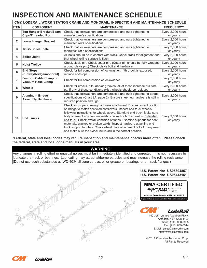
INSPECTION AND MAINTENANCE SCHEDULE
*Federal, state and local codes may require inspection and maintenance checks more often. Please check the federal, state and local code manuals in your area.
22 1/11
WARNINGAny.changes.in.rolling.effort.or.unusual.noises.must.be.immediately.identified.and.corrected...It.is.not.necessary.to.lubricate.the.track.or.bearings...Lubricating.may.attract.airborne.particles.and.may.increase.the.rolling.resistance...(Do.not.use.such.substances.as.WD-40®,.silicone.sprays,.oil.or.grease.on.bearings.or.on.track.flanges.)
140.John.James.Audubon.Pkwy.Amherst,.NY.14228-1197Phone:.(800).888-0985
Fax:.(716).689-5514E-Mail:[email protected]
http://www.cmworks.com
©.2011.Columbus.McKinnon.Corp.All.Rights.Reserved
U.S. Patent No: US05694857U.S. Patent No: US05443151
CM® LODERAIL WORK STATION CRANE AND MONORAIL: INSPECTION AND MAINTENANCE SCHEDULEITEM COMPONENT MAINTENANCE FREQUENCY*
1 Top Hanger Bracket/Beam Clips/Threaded Rod
Check.that.lockwashers.are.compressed.and.nuts.tightened.tomanufacturer’s.specifications.
Every.2,000.hours.or.yearly
2 Lower Hanger Bracket Check.that.lockwashers.are.compressed.and.nuts.tightened.tomanufacturer’s.specifications.
Every.2,000.hours.or.yearly
3 Truss Splice Plate Check.that.lockwashers.are.compressed.and.nuts.tightened.tomanufacturer’s.specifications.
Every.2,000.hours.or.yearly
4 Splice Joint All.bolts.should.be.in.contact.with.track..Check.track.for.alignment.and.that.wheel.rolling.surface.is.flush.
Every.2,000.hours.or.yearly
5 Hoist Trolley Check.clevis.pin..Check.cotter.pin..(Cotter.pin.should.be.fully.wrapped.around.clevis.pin.).Check.clevis.bolt.and.hardware.
Every.2,000.hours.or.yearly
6 End Stops(runway/bridge/monorail)
Check.for.full.compression.of.lockwasher..If.thru-bolt.is.exposed,.replace.endstops.
Every.2,000.hours.or.yearly
7 Festoon Cable Clamp or Vacuum Hose Clamp Check.for.full.compression.of.lockwasher. Every.2,000.hours.
or.yearly
8 Wheels Check.for.cracks,.pits,.and/or.grooves:.all.of.these.increase.pull.forc-es..If.any.of.these.conditions.exist,.wheels.should.be.replaced.
Every.2,000.hours.or.yearly
9 Aluminum Bridge Assembly Hardware
Check.that.lockwashers.are.compressed.and.nuts.tightened.to.torque.specifications.(Chart.2A,.page.2)..Ensure.sheer.lug.hardware.is.still.in.required.position.and.tight.
Every.2,000.hours.or.yearly
10 End Trucks
Check.for.proper.claming.hardware.attachment..Ensure.correct.position.on.bridge.to.match.speficied.cantilevers..Inspect.end.truck.wheelsfollowing.instructions.for.wheels.above..Standard.end.truck:.Make.sure.body.is.free.of.any.bent.materials,.cracked.or.broken.welds..Extended.end.truck:.Check.overall.condition.of.tubes..Examine.supports.for.bent.materials,.cracked.or.broken.welds..Inspect.hardware.attaching.end.truck.support.to.tubes..Check.wheel.plate.attachment.bolts.for.any.wear.and.make.sure.the.nylock.nut.is.still.in.the.correct.position.
Every.2,000.hours.or.yearly