Embed Size (px)
Citation preview

Read and understand this manual prior tooperating or servicing this product.
Installation, Operation & Maintenance Manual
Vertical Bandlock™2 Closure
Installation, Operation and Maintenance Manual for GD Engineering Vertical Bandlock™ 2 Closure Page 2 of 22
Rev. 09.01 © GD Engineering, 2009. All rights reserved.
IMPORTANT NOTE: No modifications, alterations or additions to this closure shall be made without the prior
written agreement of GD Engineering.
CONTENTS 1.0 Component Parts (Major Components Identification Sketches) Installation 2.0 Initial Installation 2.1 Closure Orientation 2.2 Closure Door Removal 2.3 Hydrostatic testing 2.4 Distortion 2.5 PWHT Recommendation 2.6 Masking Procedure 2.7 Closure Door Re-installation 2.8 Door Centralisation Operation 3.0 Bandlock™2 Closure Operation 3.1 Door Unlocking & Opening 3.2 Door Closing & Locking 3.3 Storage Maintenance 4.0 Locking Band Adjustment 4.1 Seal Replacement 4.2 Torque Settings 4.3 Maintenance Activity Detail 4.4 Maintenance Record Interlocks 5.0 (Refer to separate additional instructions when closure is fitted with a mechanical
key interlock) Hydraulic Davit 6.0 (Refer to separate additional instructions when closure is fitted with a hydraulic
davit)
The Bandlock™2 Closure is designed to provide safe operation at the pressure/temperature rating shown on the nameplate and to comply fully with the design conditions stated in the
purchase order.
“It is the responsibility of the end user to consider the effect or consequence of any other loading or operating conditions that might be applied in service.”
SAFETY WARNING: OBSERVE SAFETY PRECAUTIONS AT ALL TIMES
The parent vessel MUST be fully drained, isolated from any pressure source and vented before opening the vessel.
OBSERVE PERMIT TO WORK PROCEDURES AND SAFETY PRECAUTIONS AT ALL TIMES

Installation, Operation and Maintenance Manual for GD Engineering Vertical Bandlock™ 2 Closure Page 3 of 22
Rev. 09.01 © GD Engineering, 2009. All rights reserved.
1.0 VERTICAL CLOSURE COMPONENTS - WITH DAVIT (Major components identification sketch)
Fig 1.0 – Bandlock™2 Closure Components - with Davit Arm
Davit arm
Nameplate (with serial number)
Locking mechanism, Ref Fig 2.0
Band clip
Grease nipple
Centralising pin
Restraining chain and setscrew
Support bearings
Davit attachment bolt
Drain groove
Davit retaining plate (or lug)
Installation, Operation and Maintenance Manual for GD Engineering Vertical Bandlock™ 2 Closure Page 4 of 22
Rev. 09.01 © GD Engineering, 2009. All rights reserved.
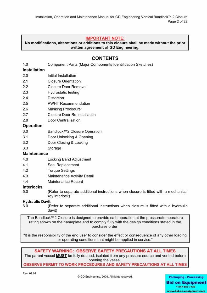
VERTICAL CLOSURE COMPONENTS - LIFT OUT
Fig 1.1 – Bandlock™2 Closure Components – Lift Out
3 Off lifting points

Installation, Operation and Maintenance Manual for GD Engineering Vertical Bandlock™ 2 Closure Page 5 of 22
Rev. 09.01 © GD Engineering, 2009. All rights reserved.
1.1 BANDLOCK™2 CLOSURE LOCKING MECHANISM COMPONENTS (Major components identification sketch)
Fig 2.0 – Bandlock™2 Closure Locking Mechanism Components
Contracted to unlock
Support Screw
Pressure Warning Screw
Horse Shoe
Locking Plate
Stop Screw
Eccentric Stop
Locking Band Lug
Drive Link
Locking Band
Installation, Operation and Maintenance Manual for GD Engineering Vertical Bandlock™ 2 Closure Page 6 of 22
Rev. 09.01 © GD Engineering, 2009. All rights reserved.
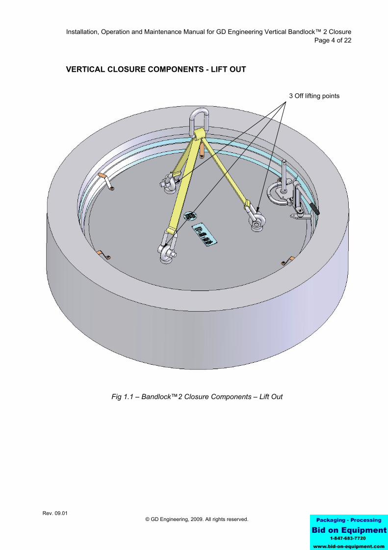
1.2 BANDLOCK™2 CLOSURE PRESSURE WARNING SCREW & LOCKING SEGMENT ASSEMBLY (Major components identification sketch)
Fig 3.0 – Seal and pressure warning screw details
WARNING
Never put the Bandlock™2 closure into service without the locking plate and pressure warning screw being fitted
Pressure Warning Screw
Locking Plate & Segment
Bandlock™2 Seal
Seal Face Vent Slot
Seal Face
Seal
Drain groove
Installation, Operation and Maintenance Manual for GD Engineering Vertical Bandlock™ 2 Closure Page 7 of 22
Rev. 09.01 © GD Engineering, 2009. All rights reserved.
2.0 INITIAL INSTALLATION 2.1 CLOSURE ORIENTATION
The GD Engineering vertical Bandlock™2 closure must be installed truly vertical.
Vessels which are required to be at an angle from the vertical should be accommodated with a mitred closure weld preparation. This leaves the closure vertical whilst accounting for the nominal angle of the vessel.
WARNING DO NOT INSTALL CLOSURES WHICH ARE NOT IN A TRULY VERTICAL POSITION
IMPORTANT NOTE:
Prior to commencement of initial installation and fabrication of the closure to any pressure vessel, it is vital that you refer to sections 2.4 and 2.5 of this manual which provides important details in respect of distortion and recommendations for closures that require post weld heat-treatment.
The Bandlock™2 closure door must always be removed prior to welding the closure to a vessel. Reference should be made to section 2.2 of this manual - Instructions for Door Removal.
IMPORTANT NOTE If you are in any doubt about the installation, maintenance or operation of this equipment, please
contact the GD Engineering Service Department. TEL +44 (0)1909 482323 email: [email protected]
Installation, Operation and Maintenance Manual for GD Engineering Vertical Bandlock™ 2 Closure Page 8 of 22
Rev. 09.01 © GD Engineering, 2009. All rights reserved.
2.2 CLOSURE DOOR REMOVAL When it is necessary during initial installation, vessel fabrication or routine maintenance,
to remove the Bandlock™2 closure door, the following procedure should be followed:
IMPORTANT NOTE The Bandlock™2 closure door must always be removed prior to welding the closure to any
pressure vessel 1 Remove the Pressure Warning Screw and Locking Plate and contract the locking band to
its 'door open' position (reference section 3.1 and 3.2 for unlocking and locking procedure).
Closures fitted with Davits (Fig 1.0)
IMPORTANT NOTE DO NOT use hand wheel to lift and swing door clear of hub before closure is welded to vessel.
Closure may over balance and cause injury or damage
2 Remove setscrew retaining chain to door. Remove davit attachment bolt and lift davit arm
clear of door. 3 Refit davit attachment bolt and using ‘D’ shackle or similar (rated for door weight) lift
closure door clear of hub. Store as recommended in section 3.3. Closures without Davits (Fig 1.1) 4 Attach 3 leg lifting equipment, (rated for closure door weight), to lifting eyes in closure
door. Lift door clear of hub and store as recommended in section 3.3.
IMPORTANT NOTE When storing the door it is important to always make sure that the seal and all machined
surfaces are adequately protected from damage 5 Strictly adhering to the above procedure will ensure ease of re-alignment of the closure
door following installation. However, particular attention should be paid to section 2.8 of this manual – Door centralisation.
IMPORTANT NOTE Ensure that centralising pins (Fig 1.0) are not damaged when closure door is being manoeuvred
into position
Installation, Operation and Maintenance Manual for GD Engineering Vertical Bandlock™ 2 Closure Page 9 of 22
Rev. 09.01 © GD Engineering, 2009. All rights reserved.
2.3 HYDROSTATIC TESTING. 1. The closure must not be hydrostatically tested at a pressure greater than 1.5x Design
Pressure (stamped on the closure nameplate). Prior to performing the hydrostatic test, the seal must be removed and both the seal and sealing groove cleaned thoroughly and a thin layer of general purpose grease applied.
2 After Hydrostatic testing:
- Ensure that closure internal surfaces (paying particular attention to the seal groove) are thoroughly dried and greased to prevent corrosion.
- It is advisable to inspect the seal for damage. This is particularly important for closures with a design pressure of 425Barg (#2500) and above. The seal must be replaced if damaged.
2.4 DISTORTION It is important that distortion due to fabrication, welding and subsequent post weld heat treatment (PWHT) is minimised. The following recommendations should be followed to minimise this risk: 1 Branch connections (in particular set-in type) should not be located within close proximity
of the joining weld (not less than the nominal diameter (ID) of the branch, between the edges of the weld).
2 The closure hub with the door removed should always be welded after the fabrication of
the vessel branch connections. 3 A minimum pre-heat temperature of 20°C should always be used, but this is dependant
upon the welding parameters of the weld procedure qualification record utilised. 4 Automatic or semi-automatic processes should be used to maintain constant heat input. 5 A staggered welding sequence should be used when the manual metallic arc process is
used. 2.5 PWHT RECOMMENDATIONS: 1 When storing the door, it is important to always make sure that the machined surfaces are
adequately protected from damage. 2 PWHT should be carried out generally in accordance with ASME VIII. 3 After PWHT, lightly emery cloth (smooth finish paper) the closure hub sealing face to
remove any deposit build up. 4 Note: do not place any loads on the hinge mounting plate during or after the PWHT
process.
IMPORTANT NOTE The closure door, seal and locking band assembly must always be removed before any welding
is carried out

Installation, Operation and Maintenance Manual for GD Engineering Vertical Bandlock™ 2 Closure Page 10 of 22
Rev. 09.01 © GD Engineering, 2009. All rights reserved.
2.6 MASKING PROCEDURE FOR PAINTING THE BANDLOCK™2 CLOSURE 1 When painting is required the areas shown ‘masked’ should not be painted but protected
with a blast proof masking material. 2 To prepare the closure for painting the locking band, pressure warning screw assembly
and seal must be removed from the door. (These components are stainless steel and do not require painting).
3 Closure door hinge bearings and all threaded holes must be suitably protected from
ingress of shot blast and paint material.
Fig 4.0 - Hub masking area.
Full band seating area protection. Apply Masking tape to areas indicated.
Plug any holes, both sides, with masking tape plugs Take care to fully protect holes
Masking may be extended to cover bore if required
Full band seating area protection Apply masking tape to areas indicated
Installation, Operation and Maintenance Manual for GD Engineering Vertical Bandlock™ 2 Closure Page 11 of 22
Rev. 09.01 © GD Engineering, 2009. All rights reserved.
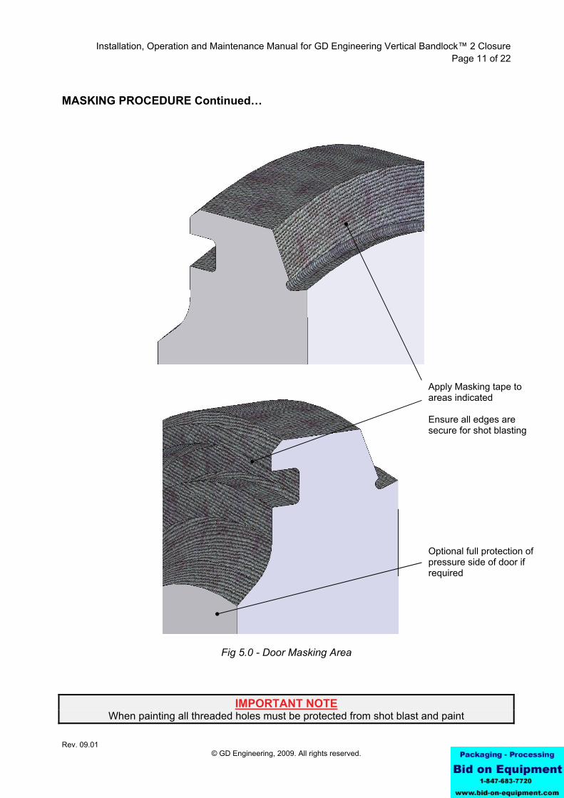
MASKING PROCEDURE Continued…
Fig 5.0 - Door Masking Area
IMPORTANT NOTE When painting all threaded holes must be protected from shot blast and paint
Apply Masking tape to areas indicated Ensure all edges are secure for shot blasting
Optional full protection of pressure side of door if required
Installation, Operation and Maintenance Manual for GD Engineering Vertical Bandlock™ 2 Closure Page 12 of 22
Rev. 09.01 © GD Engineering, 2009. All rights reserved.
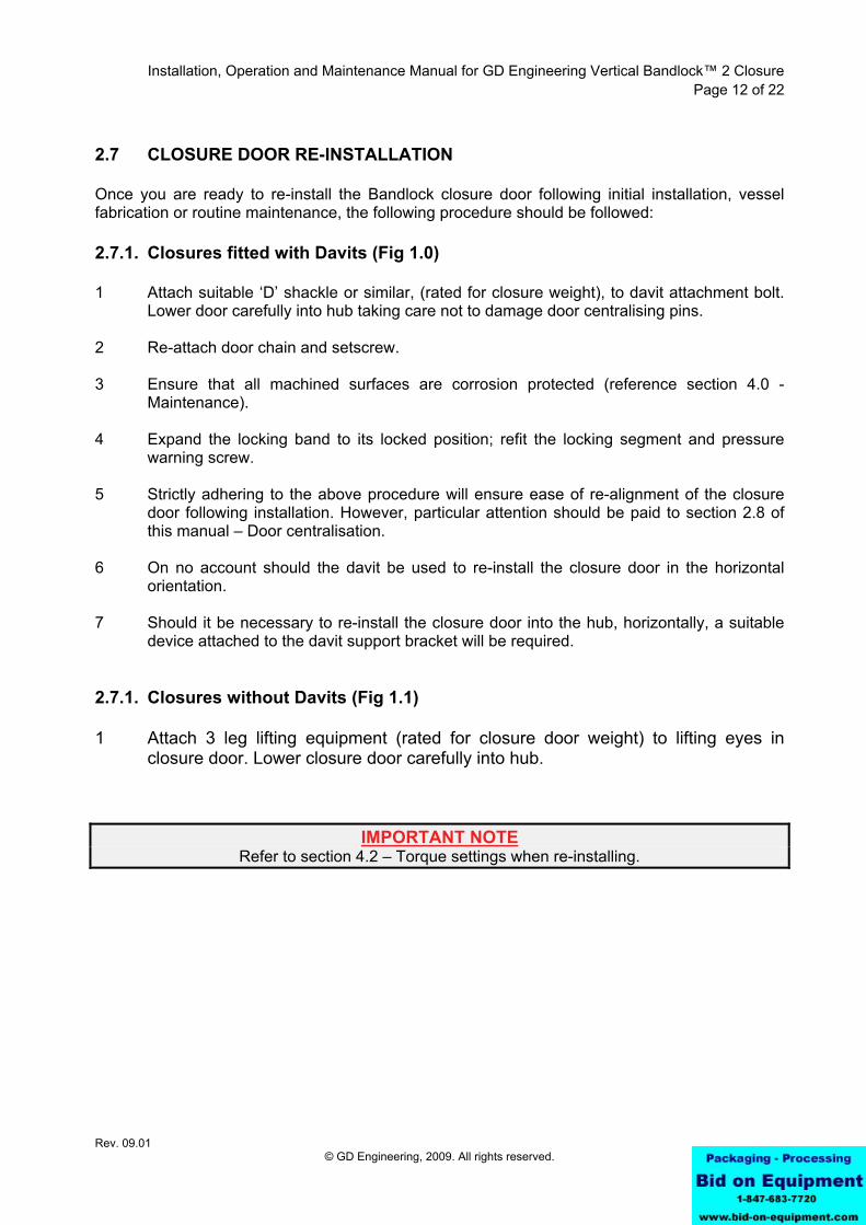
2.7 CLOSURE DOOR RE-INSTALLATION Once you are ready to re-install the Bandlock closure door following initial installation, vessel fabrication or routine maintenance, the following procedure should be followed: 2.7.1. Closures fitted with Davits (Fig 1.0) 1 Attach suitable ‘D’ shackle or similar, (rated for closure weight), to davit attachment bolt.
Lower door carefully into hub taking care not to damage door centralising pins. 2 Re-attach door chain and setscrew. 3 Ensure that all machined surfaces are corrosion protected (reference section 4.0 -
Maintenance). 4 Expand the locking band to its locked position; refit the locking segment and pressure
warning screw. 5 Strictly adhering to the above procedure will ensure ease of re-alignment of the closure
door following installation. However, particular attention should be paid to section 2.8 of this manual – Door centralisation.
6 On no account should the davit be used to re-install the closure door in the horizontal
orientation. 7 Should it be necessary to re-install the closure door into the hub, horizontally, a suitable
device attached to the davit support bracket will be required. 2.7.1. Closures without Davits (Fig 1.1) 1 Attach 3 leg lifting equipment (rated for closure door weight) to lifting eyes in
closure door. Lower closure door carefully into hub.
IMPORTANT NOTE Refer to section 4.2 – Torque settings when re-installing.

Installation, Operation and Maintenance Manual for GD Engineering Vertical Bandlock™ 2 Closure Page 13 of 22
Rev. 09.01 © GD Engineering, 2009. All rights reserved.
2.8 DOOR CENTRALISATION
All vertical Bandlock™2 closure doors are fitted with centralising pins (Fig 1.0). These pins, located around the circumference, ensure that the door is located centrally into the hub. No maintenance is required to the pins but it is recommended that a periodic visual inspection is carried out to identify any damaged or missing pins. Damaged or missing pins must be replaced. Contact GD Engineering service department for replacement. If centralising pins are damaged or missing and the door needs to be installed before repairs / maintenance can be performed, the following procedure must be adopted to ensure that the door is central in the hub: Ensure that the door is central by measuring door to hub gap (H) with feeler gauges (Fig 6.0), at four equispaced positions around the door circumference. If the door is out of central, adjust the gap as necessary until all are equal. The locking band must be contracted and the PWS assembly removed to carry out this operation.
Fig 6.0 – Door Centralisation
WARNING DO NOT pressurise the closure if the centralising pins are damaged or missing unless
absolutely necessary, and only after making sure the door is central to the hub
Installation, Operation and Maintenance Manual for GD Engineering Vertical Bandlock™ 2 Closure Page 14 of 22
Rev. 09.01 © GD Engineering, 2009. All rights reserved.
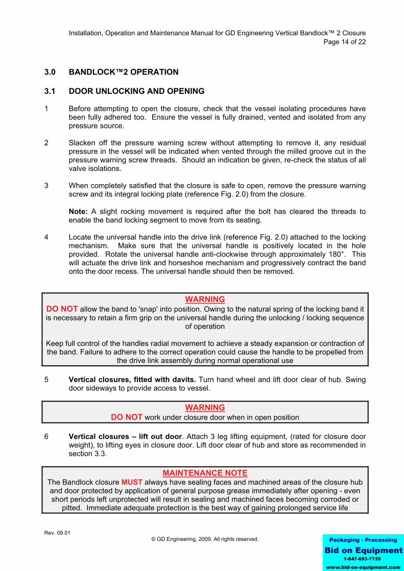
3.0 BANDLOCK™2 OPERATION 3.1 DOOR UNLOCKING AND OPENING 1 Before attempting to open the closure, check that the vessel isolating procedures have
been fully adhered too. Ensure the vessel is fully drained, vented and isolated from any pressure source.
2 Slacken off the pressure warning screw without attempting to remove it, any residual
pressure in the vessel will be indicated when vented through the milled groove cut in the pressure warning screw threads. Should an indication be given, re-check the status of all valve isolations.
3 When completely satisfied that the closure is safe to open, remove the pressure warning
screw and its integral locking plate (reference Fig. 2.0) from the closure. Note: A slight rocking movement is required after the bolt has cleared the threads to
enable the band locking segment to move from its seating. 4 Locate the universal handle into the drive link (reference Fig. 2.0) attached to the locking
mechanism. Make sure that the universal handle is positively located in the hole provided. Rotate the universal handle anti-clockwise through approximately 180°. This will actuate the drive link and horseshoe mechanism and progressively contract the band onto the door recess. The universal handle should then be removed.
WARNING DO NOT allow the band to 'snap' into position. Owing to the natural spring of the locking band it is necessary to retain a firm grip on the universal handle during the unlocking / locking sequence
of operation
Keep full control of the handles radial movement to achieve a steady expansion or contraction of the band. Failure to adhere to the correct operation could cause the handle to be propelled from
the drive link assembly during normal operational use 5 Vertical closures, fitted with davits. Turn hand wheel and lift door clear of hub. Swing
door sideways to provide access to vessel.
WARNING DO NOT work under closure door when in open position
6 Vertical closures – lift out door. Attach 3 leg lifting equipment, (rated for closure door
weight), to lifting eyes in closure door. Lift door clear of hub and store as recommended in section 3.3.
MAINTENANCE NOTE
The Bandlock closure MUST always have sealing faces and machined areas of the closure hub and door protected by application of general purpose grease immediately after opening - even short periods left unprotected will result in sealing and machined faces becoming corroded or
pitted. Immediate adequate protection is the best way of gaining prolonged service life
Installation, Operation and Maintenance Manual for GD Engineering Vertical Bandlock™ 2 Closure Page 15 of 22
Rev. 09.01 © GD Engineering, 2009. All rights reserved.
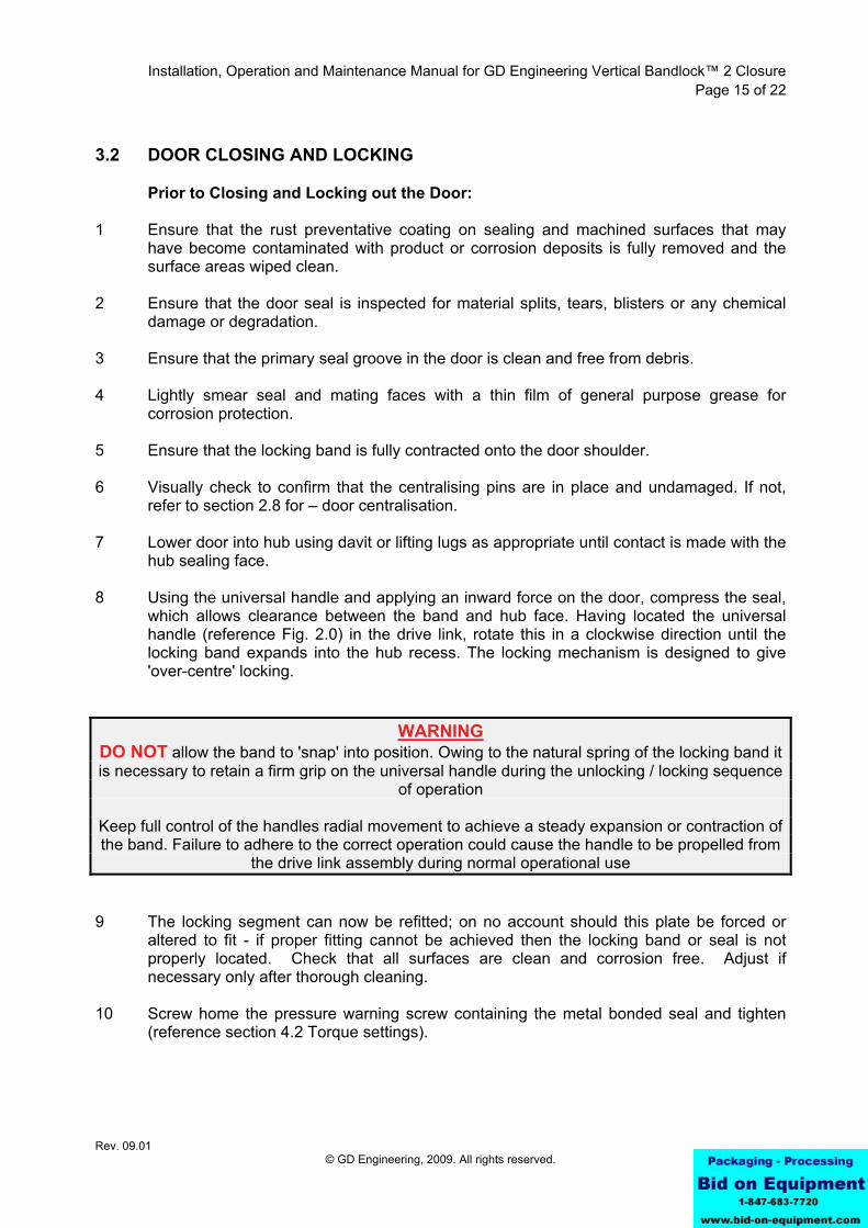
3.2 DOOR CLOSING AND LOCKING Prior to Closing and Locking out the Door: 1 Ensure that the rust preventative coating on sealing and machined surfaces that may
have become contaminated with product or corrosion deposits is fully removed and the surface areas wiped clean.
2 Ensure that the door seal is inspected for material splits, tears, blisters or any chemical
damage or degradation. 3 Ensure that the primary seal groove in the door is clean and free from debris. 4 Lightly smear seal and mating faces with a thin film of general purpose grease for
corrosion protection. 5 Ensure that the locking band is fully contracted onto the door shoulder. 6 Visually check to confirm that the centralising pins are in place and undamaged. If not,
refer to section 2.8 for – door centralisation. 7 Lower door into hub using davit or lifting lugs as appropriate until contact is made with the
hub sealing face. 8 Using the universal handle and applying an inward force on the door, compress the seal,
which allows clearance between the band and hub face. Having located the universal handle (reference Fig. 2.0) in the drive link, rotate this in a clockwise direction until the locking band expands into the hub recess. The locking mechanism is designed to give 'over-centre' locking.
WARNING DO NOT allow the band to 'snap' into position. Owing to the natural spring of the locking band it is necessary to retain a firm grip on the universal handle during the unlocking / locking sequence
of operation
Keep full control of the handles radial movement to achieve a steady expansion or contraction of the band. Failure to adhere to the correct operation could cause the handle to be propelled from
the drive link assembly during normal operational use 9 The locking segment can now be refitted; on no account should this plate be forced or
altered to fit - if proper fitting cannot be achieved then the locking band or seal is not properly located. Check that all surfaces are clean and corrosion free. Adjust if necessary only after thorough cleaning.
10 Screw home the pressure warning screw containing the metal bonded seal and tighten
(reference section 4.2 Torque settings).
Installation, Operation and Maintenance Manual for GD Engineering Vertical Bandlock™ 2 Closure Page 16 of 22
Rev. 09.01 © GD Engineering, 2009. All rights reserved.
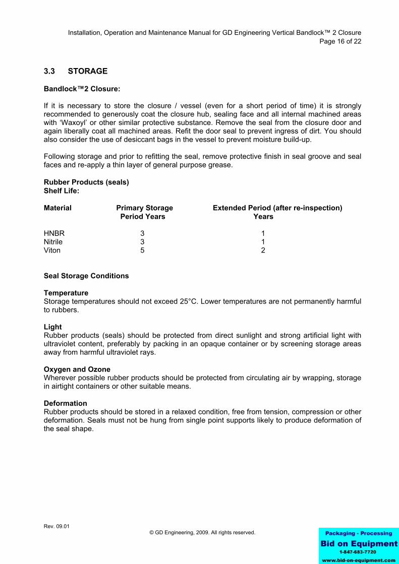
3.3 STORAGE Bandlock™2 Closure: If it is necessary to store the closure / vessel (even for a short period of time) it is strongly recommended to generously coat the closure hub, sealing face and all internal machined areas with ‘Waxoyl’ or other similar protective substance. Remove the seal from the closure door and again liberally coat all machined areas. Refit the door seal to prevent ingress of dirt. You should also consider the use of desiccant bags in the vessel to prevent moisture build-up. Following storage and prior to refitting the seal, remove protective finish in seal groove and seal faces and re-apply a thin layer of general purpose grease. Rubber Products (seals) Shelf Life: Material Primary Storage Extended Period (after re-inspection) Period Years Years HNBR 3 1 Nitrile 3 1 Viton 5 2 Seal Storage Conditions Temperature Storage temperatures should not exceed 25°C. Lower temperatures are not permanently harmful to rubbers. Light Rubber products (seals) should be protected from direct sunlight and strong artificial light with ultraviolet content, preferably by packing in an opaque container or by screening storage areas away from harmful ultraviolet rays. Oxygen and Ozone Wherever possible rubber products should be protected from circulating air by wrapping, storage in airtight containers or other suitable means. Deformation Rubber products should be stored in a relaxed condition, free from tension, compression or other deformation. Seals must not be hung from single point supports likely to produce deformation of the seal shape.
Installation, Operation and Maintenance Manual for GD Engineering Vertical Bandlock™ 2 Closure Page 17 of 22
Rev. 09.01 © GD Engineering, 2009. All rights reserved.
4.0 LOCKING BAND MECHANISM ADJUSTMENT Should it become difficult to engage the locking band, segment or pressure warning screw, it may be necessary to adjust the locking band. 1 Expand the locking band outwards to its fully 'locked' position and fit the locking segment
incorporating pressure warning screw. Both the band and locking segment should engage easily allowing the pressure warning screw to be hand tightened. If difficulties are experienced in hand tightening the pressure warning screw, the following procedure should be adhered to.
2 Adjust the eccentric stop (Fig 2.0) such that it provides a running fit for the locking band
lug (Fig 2.0) between the adjusted eccentric stop and the fixed position of support screw. 3 Secure the eccentric stop by tightening hexagon socket countersunk head screw. 4 Re-check band operation by expanding and contracting locking band (with
segment/locking plate removed). Adjust as necessary using steps 1 to 3 above.
NOTE It is advised, before final adjustment to lightly smear the locking band internal and
external sliding faces with a thin film of general purpose grease 4.1 SEAL REPLACEMENT Should it be necessary to remove the door seal from the closure, this can be achieved simply by prising the seal out of the groove with a flat bladed tool under the seal lip, making sure the seal and the seal groove is not damaged. 1 With the seal removed, the seal groove should be wiped clean of all loose impediments
and corrosion deposits. A thin layer of general purpose grease should be applied to the seal groove prior to replacing the seal.
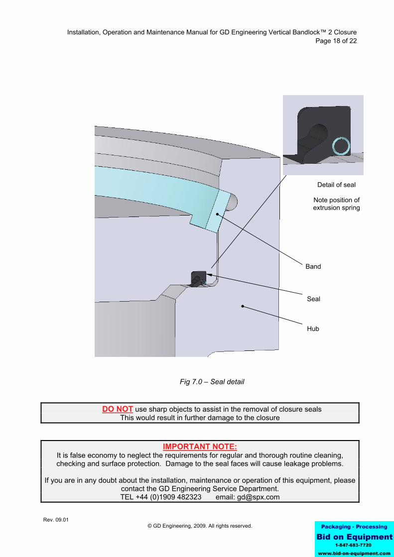
2 To refit the seal, present the seal to the groove with the energised lip of the seal
protruding outwards (reference Fig. 7.0) and press the seal into the door seal groove at the 12 o’clock position. Then press the seal into the bottom 6 o’clock ensuring that the seal is central in the groove. The seal should then be fitted at the 3 o'clock and again at the 9 o'clock position before working the seal evenly into the door seal groove.
3 Following hydrostatic testing it is advisable to inspect the seal for damage. This is
particularly important for closures with a design pressure of 425Barg (#2500) and above. The seal must be replaced if damaged.
NOTE The seal is of predetermined length and must not be altered. If surplus seal seems evident it
should be worked into the groove. Lubrication of the seal groove will assist in this operation and general seal replacement
Installation, Operation and Maintenance Manual for GD Engineering Vertical Bandlock™ 2 Closure Page 18 of 22
Rev. 09.01 © GD Engineering, 2009. All rights reserved.
Fig 7.0 – Seal detail
DO NOT use sharp objects to assist in the removal of closure seals
This would result in further damage to the closure
IMPORTANT NOTE: It is false economy to neglect the requirements for regular and thorough routine cleaning, checking and surface protection. Damage to the seal faces will cause leakage problems.
If you are in any doubt about the installation, maintenance or operation of this equipment, please
contact the GD Engineering Service Department. TEL +44 (0)1909 482323 email: [email protected]
Band
Detail of seal
Note position of extrusion spring
Hub
Seal
Installation, Operation and Maintenance Manual for GD Engineering Vertical Bandlock™ 2 Closure Page 19 of 22
Rev. 09.01 © GD Engineering, 2009. All rights reserved.
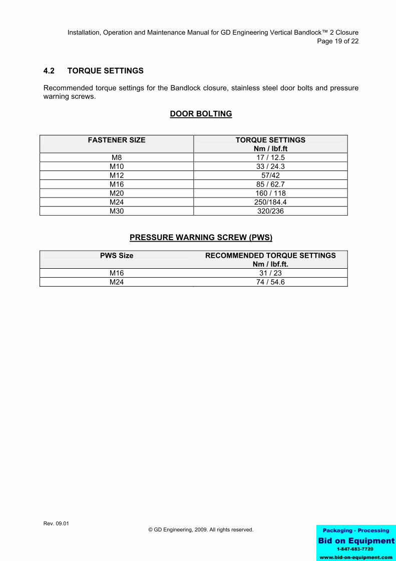
4.2 TORQUE SETTINGS Recommended torque settings for the Bandlock closure, stainless steel door bolts and pressure warning screws.
DOOR BOLTING
FASTENER SIZE TORQUE SETTINGS Nm / lbf.ft
M8 17 / 12.5 M10 33 / 24.3 M12 57/42 M16 85 / 62.7 M20 160 / 118 M24 250/184.4 M30 320/236
PRESSURE WARNING SCREW (PWS)
PWS Size RECOMMENDED TORQUE SETTINGS Nm / lbf.ft.
M16 31 / 23 M24 74 / 54.6
Installation, Operation and Maintenance Manual for GD Engineering Vertical Bandlock™ 2 Closure Page 20 of 22
Rev. 09.01 © GD Engineering, 2009. All rights reserved.
4.3 MAINTENANCE ACTIVITY DETAILS In order to maintain the Bandlock™2 closure in good working condition and to prevent operational difficulties, the following activities should be performed periodically as part of a routine maintenance schedule.
ACTIVITY DETAILS MECHANICAL MAINTENANCE - BANDLOCK™2 CLOSURE 4.3.1 Locking Band (reference Fig. 1.0) a) Clean the locking band. b) Check for any distortion within the band and the lugs to the band. Ensure that the
retaining clips are correctly installed. c) Lightly lubricate the locking band with general purpose grease. 4.3.2 Door / Closure Hub (reference Fig. 3.0) a) Check that the sealing surface of the door is clean and free from mechanical damage
and corrosion, refurbish as necessary. b) Check that the sliding surfaces of the door/band interface are clean and free from
mechanical damage and corrosion, refurbish as necessary. c) Visually inspect for thread wear and corrosion in the pressure warning screw hole. d) Check for damage to the pressure warning screw seal face. e) Lightly lubricate the locking band groove and all machined surfaces with general
purpose grease. 4.3.3 Pressure Warning Screw (reference Fig. 3.0) a) Check for thread wear, corrosion and straightness of the pressure warning screw and
check the condition of the pressure warning screw seal and replace if necessary. 4.3.4 Locking Mechanism (reference Fig. 2.0) a) Expand the locking band outwards to its ‘locked’ position and fit the locking segment
and integral pressure warning screw. With the pressure warning screw in position, check that the gap between the ends of
the locking band and segment are approximately 1/16" (1.5mm) each side. If it is necessary to reset the gap, adjust the two eccentric stops (reference Fig. 2.0)
such that they make contact with the edges of the locking band lugs whilst leaving a gap of approximately 1/16" (1.5mm) each side.
b) Secure stops by tightening hexagon socket countersunk screws.
Installation, Operation and Maintenance Manual for GD Engineering Vertical Bandlock™ 2 Closure Page 21 of 22
Rev. 09.01 © GD Engineering, 2009. All rights reserved.
4.3.5 Davit (reference Fig. 1.0) a) Check the freedom of movement of the davit and bearing. Check there is no
excessive wear. Lubricate davit screw with general purpose grease. 4.3.6 Seal a) Check the condition of the door seal and change out if necessary ensuring that the
seal is within its shelf life, as quoted on the seal packaging.
b) Lightly lubricate the seal and its mating faces with general purpose.
NOTE: Shelf life is specified as date to be used within, and then dependant of operational use, refer to
section 3.3 – Storage. 4.3.7 Leak Testing
a) Upon completion of all remedial work, and in accordance with client operational procedures we recommend that a leak and pressure test is performed to verify closure integrity.
IMPORTANT NOTE: In order to protect product integrity no unauthorised modifications or alterations must be carried
out without the prior approval of GD Engineering. Any such modifications/alterations may affect the product warranty.