Embed Size (px)
Citation preview
216308-000 rev0
INSTALLATION & OPERATION MANUAL
OIL CIRCULATING HEATING SYSTEM
MODEL
OMMOLM

(this page intentionally left blank)
iinstallation & operation manual | omm/olm heating system
IOM216308-000
Corporate & Manufacturing Headquarters5723 E. Alki Ave.Spokane, WA 99212 USA509.536.8660sales@hotstart .com
Oil & Gas Office21732 Provincial Blvd. Suite 170Katy, TX 77450 USA281.600.3700oi l .gas@hotstart .com
Europe OfficeHOTSTART GmbHAm Turm 8653721 Siegburg, Germany+49.2241.12734.0europe@hotstart .com
Asia Pacific OfficeHOTSTART Asia Pacific Ltd.2-27-15-4F HonkomagomeBunkyo-ku, Tokyo113-0021, Japan+81.3.6902.0551apac@hotstart .com
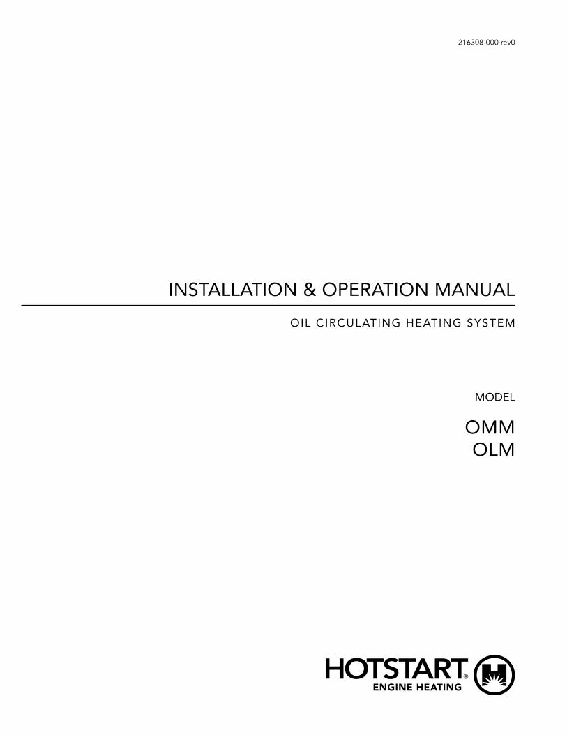
NOTE Typical heating system identification plate. Your identification plate may vary.
IDENTIFYING YOUR SYSTEMThe HOTSTART heating system is designed to heat fluids for use in marine propulsion, diesel-powered generator sets, locomotives, gas compression or any large-engine applications. The system is pre-wired, pre-plumbed and assembled on steel plate. Each heating system has an identification plate which includes the part number and serial number.
When ordering replacement parts, be sure to reference your heating system’s model number and serial number found on the identification plate and following label:
WARRANTY INFORMATIONWarranty information can be found at www.hotstart .com or by contacting our customer service department at 509.536.8660 . Have your model number and serial number ready when contacting the warranty department.
COPYRIGHTHotstart Manufacturing, Inc. is the owner of all trademarks and copyrightable material contained herein; all rights are reserved; no form of reproduction is authorized without prior written consent from Hotstart Manufacturing, Inc.
ii installation & operation manual | omm/olm heating system
IMPORTANT SAFETY INFORMATION
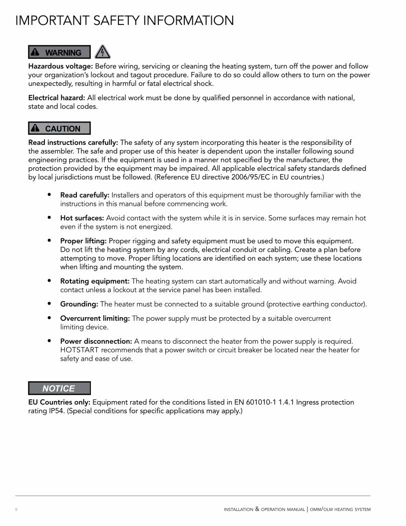
WARNING!Hazardous voltage: Before wiring, servicing or cleaning the heating system, turn off the power and follow your organization’s lockout and tagout procedure. Failure to do so could allow others to turn on the power unexpectedly, resulting in harmful or fatal electrical shock.
Electrical hazard: All electrical work must be done by qualified personnel in accordance with national, state and local codes.
CAUTION!Read instructions carefully: The safety of any system incorporating this heater is the responsibility of the assembler. The safe and proper use of this heater is dependent upon the installer following sound engineering practices. If the equipment is used in a manner not specified by the manufacturer, the protection provided by the equipment may be impaired. All applicable electrical safety standards defined by local jurisdictions must be followed. (Reference EU directive 2006/95/EC in EU countries.)
• Read carefully: Installers and operators of this equipment must be thoroughly familiar with the instructions in this manual before commencing work.
• Hot surfaces: Avoid contact with the system while it is in service. Some surfaces may remain hot even if the system is not energized.
• Proper lifting: Proper rigging and safety equipment must be used to move this equipment. Do not lift the heating system by any cords, electrical conduit or cabling. Create a plan before attempting to move. Proper lifting locations are identified on each system; use these locations when lifting and mounting the system.
• Rotating equipment: The heating system can start automatically and without warning. Avoid contact unless a lockout at the service panel has been installed.
• Grounding: The heater must be connected to a suitable ground (protective earthing conductor).
• Overcurrent limiting: The power supply must be protected by a suitable overcurrent limiting device.
• Power disconnection: A means to disconnect the heater from the power supply is required. HOTSTART recommends that a power switch or circuit breaker be located near the heater for safety and ease of use.
NOTICEEU Countries only: Equipment rated for the conditions listed in EN 601010-1 1.4.1 Ingress protection rating IP54. (Special conditions for specific applications may apply.)
iiiinstallation & operation manual | omm/olm heating system
TABLE OF CONTENTS
IDENTIFYING YOUR SYSTEM | I
WARRANTY INFORMATION | I
COPYRIGHT | I
IMPORTANT SAFETY INFORMATION | II
1 OVERVIEW | 1
1.1 HEATING SYSTEM COMPONENTS | 1
1.2 OPERATION OVERVIEW | 2
2 PLUMBING INSTALLATION | 3
2.1 OIL PLUMBING INSTALLATION | 4
2.1.1 Oil Supply | 4
2.1.2 Oil Return | 4
2.1.3 Oil Pressure Relief Valve | 4
2.2 OIL PLUMBING ILLUSTRATION | 5
2.3 PRESSURIZED SYSTEM INSTALLATION | 6
2.4 MOUNTING | 7
2.4.1 Tank and Pump | 7
2.5 MAIN POWER SUPPLY | 8
2.6 CUSTOMER INTERFACE CONNECTIONS | 9
3 SYSTEM COMPONENTS AND OPERATION | 10
3.1 LOCAL/OFF/REMOTE SWITCH | 10
3.2 PRIME BUTTON | 10
3.3 OIL PRESSURE/TEMPERATURE GAUGE | 10
3.4 PRESSURE RELIEF VALVE | 11
3.5 MOTOR PROTECTION SWITCH (MPS) | 12
3.6 HIGH-LIMIT TCR (TEMPERATURE CONTROL RELAY) | 12
3.7 CONTROL TCR (TEMPERATURE CONTROL RELAY) | 12
4 HEATING SYSTEM START-UP | 13
5 MAINTENANCE, REPAIR AND TROUBLESHOOTING | 14
5.1 FAULTS | 14
iv installation & operation manual | omm/olm heating system
5.2 SYSTEM MAINTENANCE | 14
5.2.1 Plumbing Connections | 14
5.2.2 Electrical Connections | 14
5.2.3 System Mounting | 14
5.2.4 Magnetic Contactors | 15
5.2.5 Pump Seal | 15
5.2.6 Motor Lubrication | 15
5.2.7 Oil Pressure Relief Valve | 15
5.2.8 Oil Pressure/Temperature Gauge | 15
5.2.9 Volatile Corrosion Inhibitor (VCI) | 15
5.2.10 Temperature Control Relay (TCR) | 16
5.2.11 Resistance Temperature Device (RTD) | 17
5.2.12 Heating Tank/Element | 18
5.2.13 Reassembly of Heating Element and Tank | 18
5.3 RECOMMENDED MAINTENANCE | 20
5.4 STORAGE REQUIREMENTS | 20
5.5 TROUBLESHOOTING | 21
TABLE OF CONTENTS
1installation & operation manual | omm/olm heating system
1 OVERVIEW
1.1 HEATING SYSTEM COMPONENTS
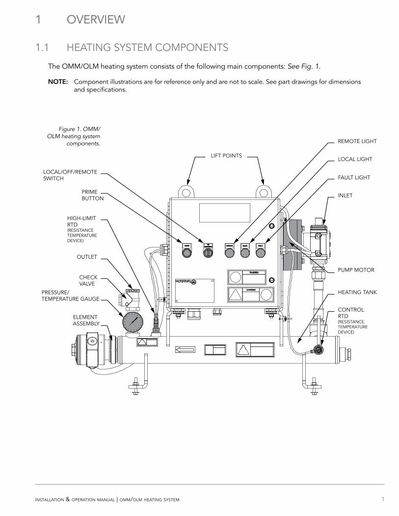
The OMM/OLM heating system consists of the following main components: See Fig. 1.
OOE: Component illustrations are for reference only and are not to scale. See part drawings for dimensions and specifications.
Figure 1. OMM/OLM heating system
components.
CHECK VALVE
OUTLET
PRESSURE/TEMPERATURE GAUGE
PRIMEBUTTON
LOCAL/OFF/REMOTESWITCH
ELEMENT ASSEMBLY
HIGH-LIMITRTD(RESISTANCE TEMPERATURE DEVICE)
HEATING TANK
CONTROL RTD(RESISTANCE TEMPERATURE DEVICE)
REMOTE LIGHT
LOCAL LIGHT
FAULT LIGHT
INLET
PUMP MOTOR
LIFT POINTS
2 installation & operation manual | omm/olm heating system
1.2 OPERATION OVERVIEW
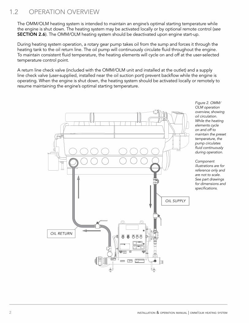
The OMM/OLM heating system is intended to maintain an engine’s optimal starting temperature while the engine is shut down. The heating system may be activated locally or by optional remote control (see SECOIO 2.6). The OMM/OLM heating system should be deactivated upon engine start-up.
During heating system operation, a rotary gear pump takes oil from the sump and forces it through the heating tank to the oil return line. The oil pump will continuously circulate fluid throughout the engine. To maintain consistent fluid temperature, the heating elements will cycle on and off at the user-selected temperature control point.
A return line check valve (included with the OMM/OLM unit and installed at the outlet) and a supply line check valve (user-supplied, installed near the oil suction port) prevent backflow while the engine is operating. When the engine is shut down, the heating system should be activated locally or remotely to resume maintaining the engine’s optimal starting temperature.
Figure 2. OMM/OLM operation overview, showing oil circulation. While the heating elements cycle on and off to maintain the preset temperature, the pump circulates fluid continuously during operation.
Component illustrations are for reference only and are not to scale. See part drawings for dimensions and specifications.
OIL RETURN
OIL SUPPLY
3installation & operation manual | omm/olm heating system
2 PLUMBING INSTALLATION
CAUTION!Pressure hazard: Power must be turned off and locked out at the service panel when the isolation valves are in the closed position. Failure to do so may cause damage to heating system components, damage to lubrication oil, fluid leaks and unexpected release of heated fluid.
Overheating hazard: After completing line installation, top off the fluid levels to compensate for the fluid used to fill the lines and heating tank. Do not operate the heating system without the presence of fluid. Position the heating tank to ensure it is completely full of fluid while in operation.
Pump priming: Fill the supply line with fluid. Pump is self-priming. However, fluid must be present in the pump before start-up. Trapped air inside the pump will cause pump and seal damage.
Pump seal damage: Do not reduce the oil supply line to an inner diameter smaller than the pump inlet; pump seal damage will occur.
Check valve: HOTSTART recommends installing a user-supplied swing-type or full-flow check valve to prevent oil from flowing back into the oil sump. If the pump is installed above the minimum oil level, a check valve must be installed.
Pressure relief valve: If the OMM/OLM heating system is for use with a closed, pressurized fluid system, additional, user-supplied pressure relief must be installed along the heating system outlet plumbing. User-supplied pressure relief valve plumbing must be routed back to oil sump, oil tank or atmospheric pressure. Do not route pressure relief plumbing back to heating system tank.
Isolation valves: HOTSTART recommends installing full-flow ball valves to isolate the heating system in order to perform service on the system or engine without draining oil.
4 installation & operation manual | omm/olm heating system
2.1 OIL PLUMBING INSTALLATION
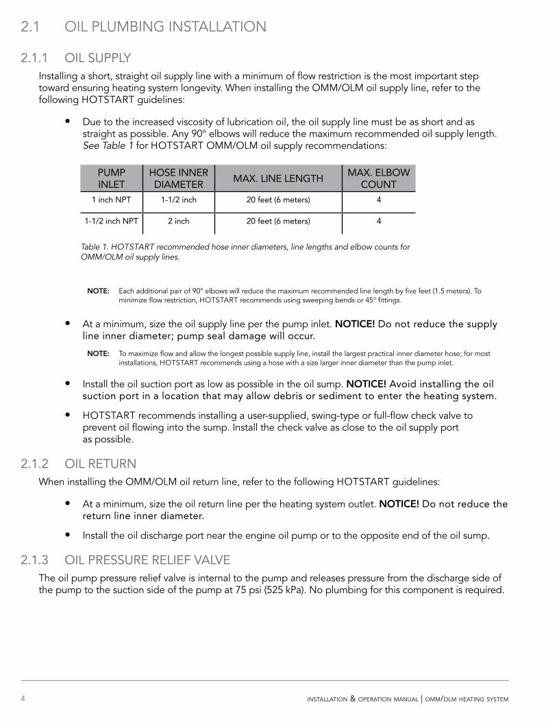
2.1.1 OIL SUPPLYInstalling a short, straight oil supply line with a minimum of flow restriction is the most important step toward ensuring heating system longevity. When installing the OMM/OLM oil supply line, refer to the following HOTSTART guidelines:
• Due to the increased viscosity of lubrication oil, the oil supply line must be as short and as straight as possible. Any 90° elbows will reduce the maximum recommended oil supply length. See Table 1 for HOTSTART OMM/OLM oil supply recommendations:
OOE: Each additional pair of 90° elbows will reduce the maximum recommended line length by five feet (1.5 meters). To minimize flow restriction, HOTSTART recommends using sweeping bends or 45° fittings.
• At a minimum, size the oil supply line per the pump inlet. OOICE! Do not reduce the supply line inner diameter; pump seal damage will occur.
OOE: To maximize flow and allow the longest possible supply line, install the largest practical inner diameter hose; for most installations, HOTSTART recommends using a hose with a size larger inner diameter than the pump inlet.
• Install the oil suction port as low as possible in the oil sump. OOICE! Avoid installing the oil suction port in a location that may allow debris or sediment to enter the heating system.
• HOTSTART recommends installing a user-supplied, swing-type or full-flow check valve to prevent oil flowing into the sump. Install the check valve as close to the oil supply port as possible.
2.1.2 OIL RETURNWhen installing the OMM/OLM oil return line, refer to the following HOTSTART guidelines:
• At a minimum, size the oil return line per the heating system outlet. OOICE! Do not reduce the return line inner diameter.
• Install the oil discharge port near the engine oil pump or to the opposite end of the oil sump.
2.1.3 OIL PRESSURE RELIEF VALVEThe oil pump pressure relief valve is internal to the pump and releases pressure from the discharge side of the pump to the suction side of the pump at 75 psi (525 kPa). No plumbing for this component is required.
Table 1. HOTSTART recommended hose inner diameters, line lengths and elbow counts for OMM/OLM oil supply lines.
PUMP INLET
HOSE INNER DIAMETER
MAX. LINE LENGTHMAX. ELBOW
COUNT1 inch NPT 1-1/2 inch 20 feet (6 meters) 4
1-1/2 inch NPT 2 inch 20 feet (6 meters) 4
5installation & operation manual | omm/olm heating system
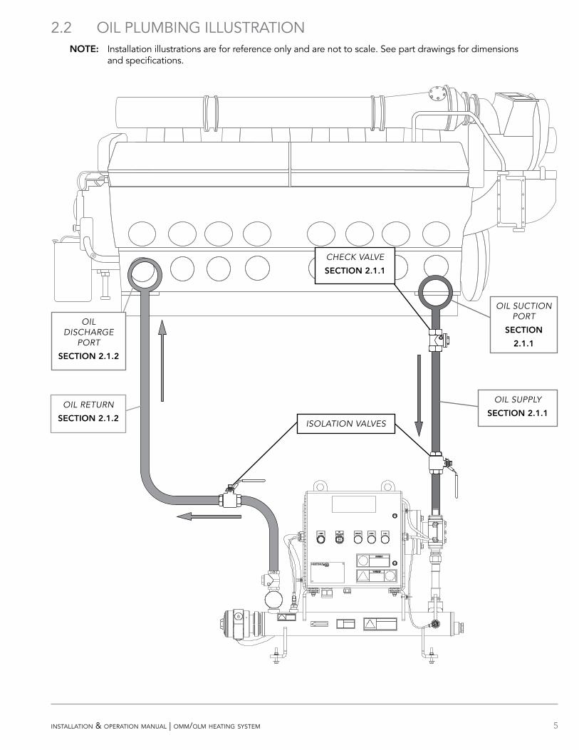
2.2 OIL PLUMBING ILLUSTRATION OOE: Installation illustrations are for reference only and are not to scale. See part drawings for dimensions
and specifications.
OIL RETURN
SECOIO 2.1.2
OIL SUPPLY
SECOIO 2.1.1
OIL DISCHARGE
PORT
SECOIO 2.1.2
OIL SUCTION PORT
SECOIO
2.1.1
ISOLATION VALVES
CHECK VALVE
SECOIO 2.1.1
6 installation & operation manual | omm/olm heating system
2.3 PRESSURIZED SYSTEM INSTALLATION
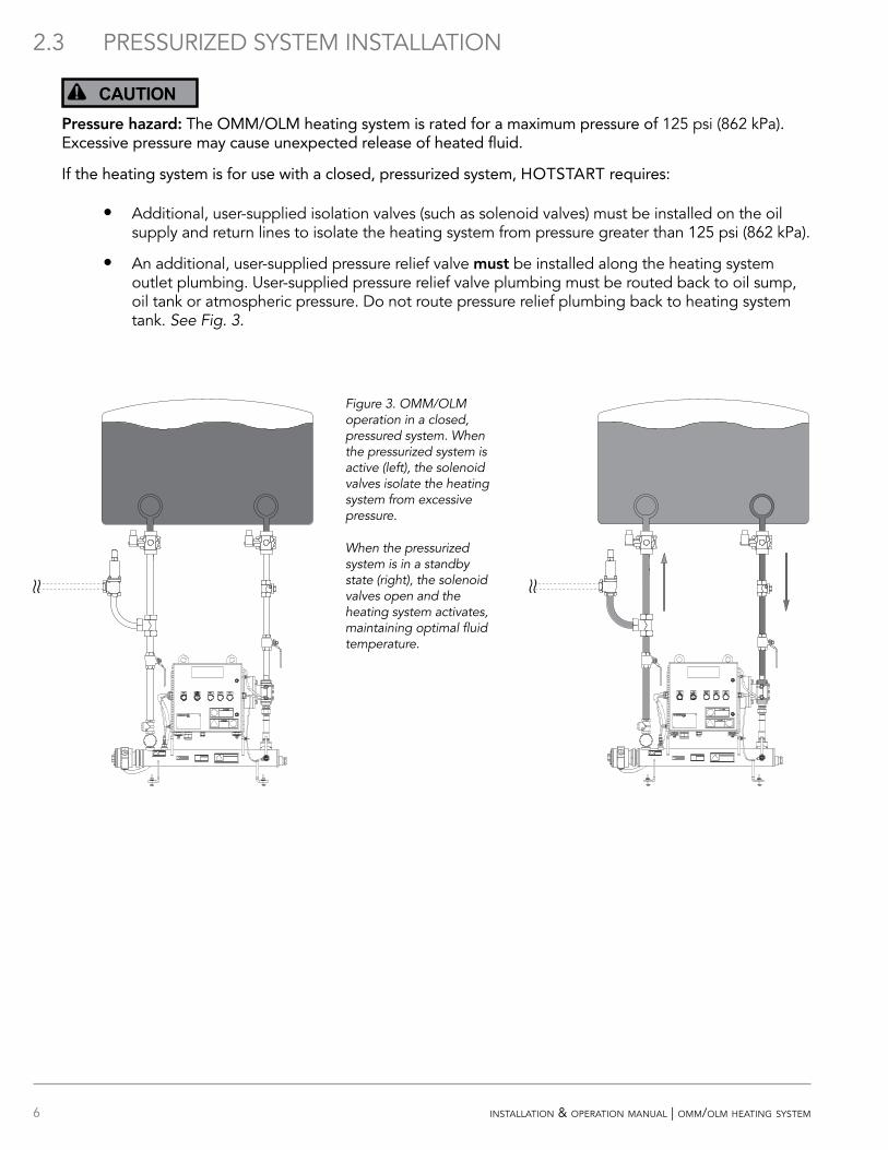
CAUTION!Pressure hazard: The OMM/OLM heating system is rated for a maximum pressure of 125 psi (862 kPa). Excessive pressure may cause unexpected release of heated fluid.
If the heating system is for use with a closed, pressurized system, HOTSTART requires:
• Additional, user-supplied isolation valves (such as solenoid valves) must be installed on the oil supply and return lines to isolate the heating system from pressure greater than 125 psi (862 kPa).
• An additional, user-supplied pressure relief valve must be installed along the heating system outlet plumbing. User-supplied pressure relief valve plumbing must be routed back to oil sump, oil tank or atmospheric pressure. Do not route pressure relief plumbing back to heating system tank. See Fig. 3.
Figure 3. OMM/OLM operation in a closed, pressured system. When the pressurized system is active (left), the solenoid valves isolate the heating system from excessive pressure.
When the pressurized system is in a standby state (right), the solenoid valves open and the heating system activates, maintaining optimal fluid temperature.
7installation & operation manual | omm/olm heating system
2.4 MOUNTING
CAUTION!Lifting hazard: Proper rigging and safety equipment must be used to move this equipment. Do not lift the heating system by any cords, electrical conduit or cabling. Create a plan before attempting to move. Proper lifting locations are identified on each system; use these locations when lifting and mounting the system.
Overheating hazard: When mounting the heating tank, position the tank so that it is completely full of fluid while in operation.
NOTICEHeating system damage: Engine vibration will damage the heating system; isolate the heating system from vibration. Never mount the heating system or components directly to the engine. If the heating system is installed using rigid pipe, use a section of flexible hose to the supply and return ports to isolate the heating system from engine vibration.
Improper mounting hazard: Reference heating system component drawings before mounting the system. Unless mounted properly, the heating system will be unstable.
2.4.1 TANK AND PUMP Mount the heater in a horizontal orientation with the heating tank directly below the control box and pump. Reference drawings for mounting position. When installing the heating system, note that the tank requires a minimum of 30 inches (63.5 cm) of clearance to remove element for maintenance. See SECOIO 5.2.12.
8 installation & operation manual | omm/olm heating system
2.5 MAIN POWER SUPPLY
WARNING!Hazardous voltage: Before wiring, servicing or cleaning the heating system, turn off the power and follow your organization’s lockout and tagout procedure. Failure to do so could allow others to turn on the power unexpectedly, resulting in harmful or fatal electrical shock.
Electrical hazard: All wiring shall be done by qualified personnel in accordance with national, state and local codes. Each system shall be grounded in accordance with the National Electrical Code. Failure to properly ground the system may result in electrical shock.
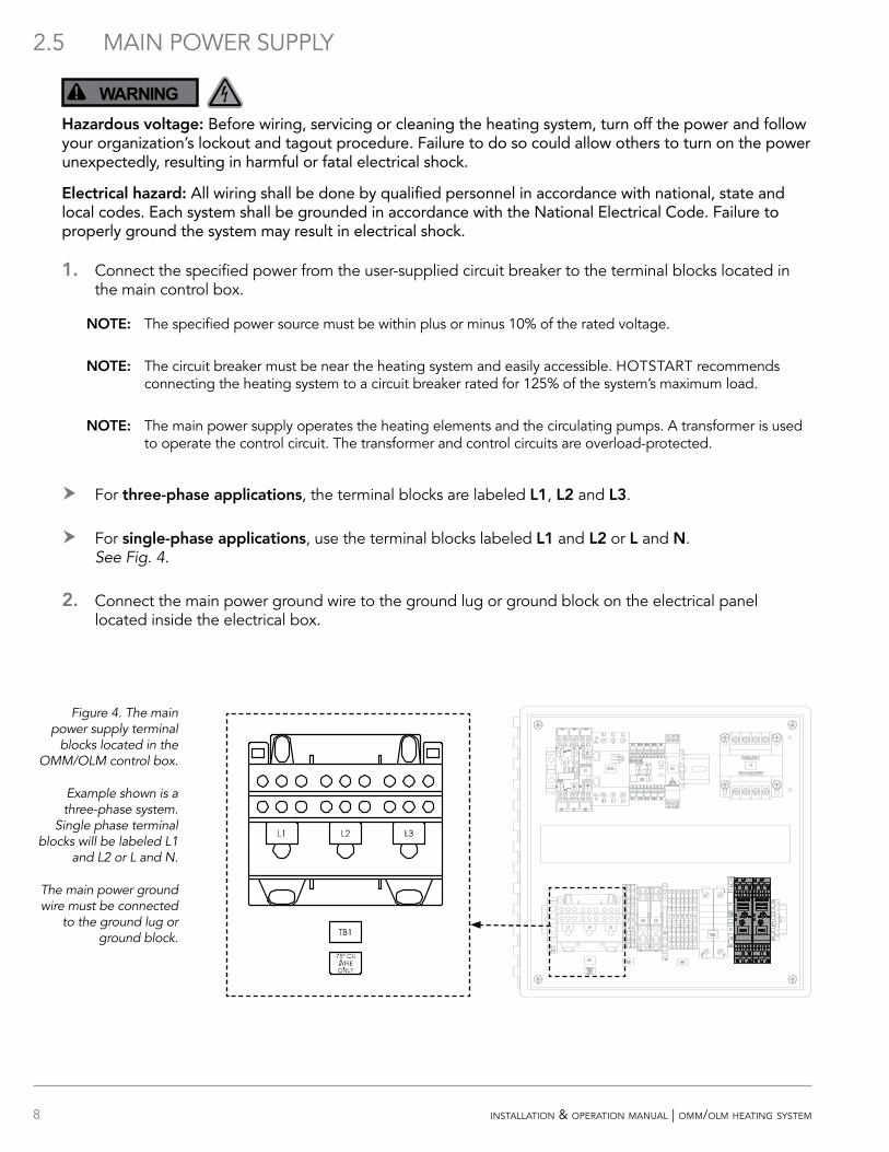
1. Connect the specified power from the user-supplied circuit breaker to the terminal blocks located in the main control box.
OOE: The specified power source must be within plus or minus 10% of the rated voltage.
OOE: The circuit breaker must be near the heating system and easily accessible. HOTSTART recommends connecting the heating system to a circuit breaker rated for 125% of the system’s maximum load.
OOE: The main power supply operates the heating elements and the circulating pumps. A transformer is used to operate the control circuit. The transformer and control circuits are overload-protected.
h For three-phase applications, the terminal blocks are labeled L1, L2 and L3.
h For single-phase applications, use the terminal blocks labeled L1 and L2 or L and . See Fig. 4.
2. Connect the main power ground wire to the ground lug or ground block on the electrical panel located inside the electrical box.
Figure 4. The main power supply terminal
blocks located in the OMM/OLM control box.
Example shown is a three-phase system.
Single phase terminal blocks will be labeled L1
and L2 or L and N.
The main power ground wire must be connected
to the ground lug or ground block.
9installation & operation manual | omm/olm heating system
2.6 CUSTOMER INTERFACE CONNECTIONS
WARNING!Hazardous voltage: Before wiring, servicing or cleaning the heating system, turn off the power and follow your organization’s lockout and tagout procedure. Failure to do so could allow others to turn on the power unexpectedly, resulting in harmful or fatal electrical shock.
Electrical hazard: All wiring shall be done by qualified personnel in accordance with national, state and local codes. Each system shall be grounded in accordance with the National Electrical Code. Failure to properly ground the system may result in electrical shock.
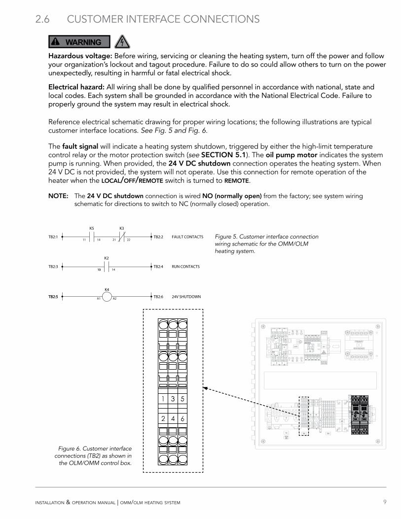
Reference electrical schematic drawing for proper wiring locations; the following illustrations are typical customer interface locations. See Fig. 5 and Fig. 6.
The fault signal will indicate a heating system shutdown, triggered by either the high-limit temperature control relay or the motor protection switch (see SECOIO 5.1). The oil pump motor indicates the system pump is running. When provided, the 24 V DC shutdown connection operates the heating system. When 24 V DC is not provided, the system will not operate. Use this connection for remote operation of the heater when the local/off/remote switch is turned to remote.
OOE: The 24 V DC shutdown connection is wired O (normally open) from the factory; see system wiring schematic for directions to switch to NC (normally closed) operation.
TB2:3
TB2:5TB2:5
TB2:1 TB2:2
TB2:4
TB2:6
K2
K5 K3
K4
24 V SHUTDOWN
RUN CONTACTS
FAULT CONTACTS11 14 21 22
1313 14
A1 A2
Figure 5. Customer interface connection wiring schematic for the OMM/OLM heating system.
Figure 6. Customer interface connections (TB2) as shown in
the OLM/OMM control box.

10 installation & operation manual | omm/olm heating system
3 SYSTEM COMPONENTS AND OPERATIONThe following is an operation description for the standard parts located in the system.
OOE: Parts in the control box may vary depending on the particular system configuration purchased.
3.1 LOCAL/OFF/REMOTE SWITCH
• local – The system is on. This mode is independent of the remote control relay. The local light will illuminate. See Fig 7.
• off – The system is shut off.
• remote – The system will turn on or off via the remote control relay. See SECOIO 2.6. The remote light will illuminate.
3.2 PRIME BUTTON
Press and hold the prime button to energize the pump motor in order to remove any air in the heating system without energizing the elements.
3.3 OIL PRESSURE/TEMPERATURE GAUGE
The OMM/OLM model features a temperature/pressure gauge mounted at the outlet of the heating tank. The gauge will indicate a pressure increase when the pump motor is engaged by pressing the prime button or during normal operation. The gauge will also indicate the current fluid temperature.
OOE: Your system’s operating pressure may vary depending on the configuration of the engine.
PRIME FAULTLOCAL REMOTE
OFF
PRIME FAULTLOCAL REMOTE
OFF
Figure 7. Local/Off/Remote switch and Prime button as shown on OMM/OLM control box.
11installation & operation manual | omm/olm heating system
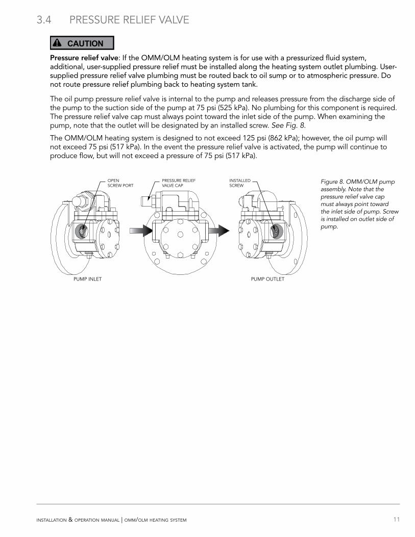
3.4 PRESSURE RELIEF VALVE
CAUTION!Pressure relief valve: If the OMM/OLM heating system is for use with a pressurized fluid system, additional, user-supplied pressure relief must be installed along the heating system outlet plumbing. User-supplied pressure relief valve plumbing must be routed back to oil sump or to atmospheric pressure. Do not route pressure relief plumbing back to heating system tank.
The oil pump pressure relief valve is internal to the pump and releases pressure from the discharge side of the pump to the suction side of the pump at 75 psi (525 kPa). No plumbing for this component is required. The pressure relief valve cap must always point toward the inlet side of the pump. When examining the pump, note that the outlet will be designated by an installed screw. See Fig. 8.
The OMM/OLM heating system is designed to not exceed 125 psi (862 kPa); however, the oil pump will not exceed 75 psi (517 kPa). In the event the pressure relief valve is activated, the pump will continue to produce flow, but will not exceed a pressure of 75 psi (517 kPa).
OPEN SCREW PORT
PRESSURE RELIEF VALVE CAP
INSTALLED SCREW
PUMP INLET PUMP OUTLET
Figure 8. OMM/OLM pump assembly. Note that the pressure relief valve cap must always point toward the inlet side of pump. Screw is installed on outlet side of pump.
12 installation & operation manual | omm/olm heating system
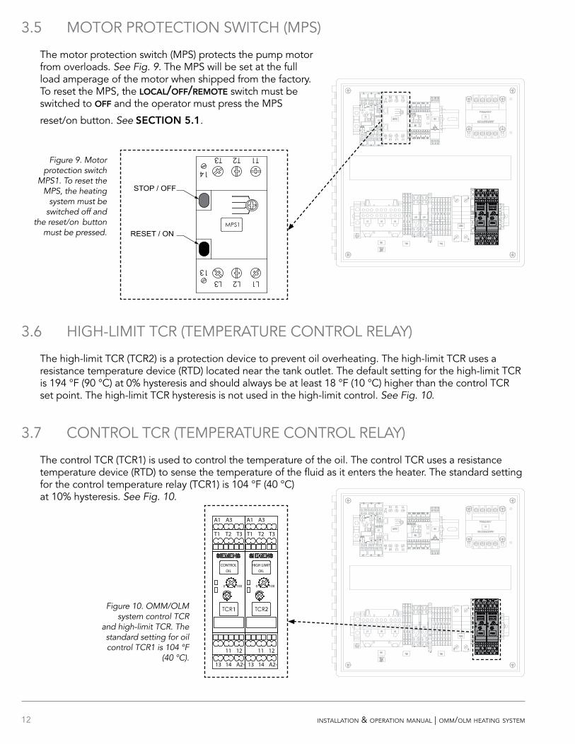
3.5 MOTOR PROTECTION SWITCH (MPS)
The motor protection switch (MPS) protects the pump motor from overloads. See Fig. 9. The MPS will be set at the full load amperage of the motor when shipped from the factory. To reset the MPS, the local/off/remote switch must be switched to off and the operator must press the MPS
reset/on button. See SECOIO 5.1.
3.6 HIGH-LIMIT TCR (TEMPERATURE CONTROL RELAY)
The high-limit TCR (TCR2) is a protection device to prevent oil overheating. The high-limit TCR uses a resistance temperature device (RTD) located near the tank outlet. The default setting for the high-limit TCR is 194 °F (90 °C) at 0% hysteresis and should always be at least 18 °F (10 °C) higher than the control TCR set point. The high-limit TCR hysteresis is not used in the high-limit control. See Fig. 10.
3.7 CONTROL TCR (TEMPERATURE CONTROL RELAY)
The control TCR (TCR1) is used to control the temperature of the oil. The control TCR uses a resistance temperature device (RTD) to sense the temperature of the fluid as it enters the heater. The standard setting for the control temperature relay (TCR1) is 104 °F (40 °C) at 10% hysteresis. See Fig. 10.
100100 00
11 12 11 12
13 14 A2-13 14 A2-
A3A1A3A1
T1 T2 T3T1 T2 T3
CONTROLOIL
HIGH LIMITOIL
1 2Figure 10. OMM/OLM system control TCR
and high-limit TCR. The standard setting for oil control TCR1 is 104 °F
(40 °C).
RESET / ON
STOP / OFF
Figure 9. Motor protection switch
MPS1. To reset the MPS, the heating
system must be switched off and
the reset/on button must be pressed.
13installation & operation manual | omm/olm heating system
4 HEATING SYSTEM START-UP
WARNING!Hazardous voltage: Before wiring, servicing or cleaning the heating system, turn off the power and follow your organization’s lockout and tagout procedure. Failure to do so could allow others to turn on the power unexpectedly, resulting in harmful or fatal electrical shock.
NOTICEPump damage: Do not run the motor/pump assembly dry for more than a few seconds. Running a pump that is not completely filled with fluid will cause damage to the pump seal.
Proper heating operation: The high-limit temperature control relay (TCR2) must be set at least 18 °F (10 °C) higher than the control temperature control relay (TCR1) for proper heating operation. This will prevent nuisance tripping of the high-limit circuit.
1. Check and tighten all electrical and plumbing connections.
2. Ensure isolation valves are open before energizing the system.
3. Check the pump for proper rotation. OOICE! Do not run the motor/pump assembly dry for more than a few seconds.
h For three-phase heating systems, press and hold the prime button while observing the rotation of the pump motor fan at the rear of the motor. If the pump motor is not rotating in the correct direction, switch any two electrical leads at the main power terminal block. See SECOIO 2.5.
h Single-phase systems are prewired to ensure the pump motor rotates in the correct direction.
4. Bleed all trapped air from the heating system by opening a plug or pipe fitting at or near the pump. Press and hold the prime button to evacuate any remaining air in the lines.
OOE: When priming the pump, the pressure gauge should indicate an increase in pressure. Your system’s operating pressure may vary depending on the configuration of the engine.
5. Turn the local/off/remote switch to local or remote to energize the heating system.
6. Once operation is satisfactory, turn the control dial on the temperature control relay TCR1 to the desired temperature setting for engine oil. HOTSTART recommends a control temperature on TCR1 of 104 °F (40 °C). The high-limit temperature setting on TCR2 should be set at 194 °F (90 °C). See SECOIO 3.6 and SECOIO 3.7.
14 installation & operation manual | omm/olm heating system
5 MAINTENANCE, REPAIR AND TROUBLESHOOTING
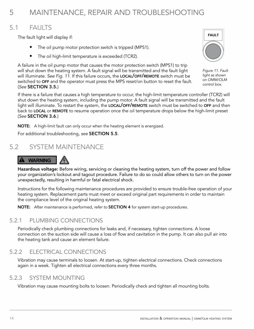
5.1 FAULTSThe fault light will display if:
• The oil pump motor protection switch is tripped (MPS1).
• The oil high-limit temperature is exceeded (TCR2).
A failure in the oil pump motor that causes the motor protection switch (MPS1) to trip will shut down the heating system. A fault signal will be transmitted and the fault light will illuminate. See Fig. 11. If this failure occurs, the local/off/remote switch must be switched to off and the operator must press the MPS reset/on button to reset the fault. (See SECOIO 3.5.)
If there is a failure that causes a high temperature to occur, the high-limit temperature controller (TCR2) will shut down the heating system, including the pump motor. A fault signal will be transmitted and the fault light will illuminate. To restart the system, the local/off/remote switch must be switched to off and then back to local or remote to resume operation once the oil temperature drops below the high-limit preset (See SECOIO 3.6.)
OOE: A high-limit fault can only occur when the heating element is energized.
For additional troubleshooting, see SECOIO 5.5.
5.2 SYSTEM MAINTENANCE
WARNING!Hazardous voltage: Before wiring, servicing or cleaning the heating system, turn off the power and follow your organization’s lockout and tagout procedure. Failure to do so could allow others to turn on the power unexpectedly, resulting in harmful or fatal electrical shock.
Instructions for the following maintenance procedures are provided to ensure trouble-free operation of your heating system. Replacement parts must meet or exceed original part requirements in order to maintain the compliance level of the original heating system.
OOE: After maintenance is performed, refer to SECOIO 4 for system start-up procedures.
5.2.1 PLUMBING CONNECTIONSPeriodically check plumbing connections for leaks and, if necessary, tighten connections. A loose connection on the suction side will cause a loss of flow and cavitation in the pump. It can also pull air into the heating tank and cause an element failure.
5.2.2 ELECTRICAL CONNECTIONSVibration may cause terminals to loosen. At start-up, tighten electrical connections. Check connections again in a week. Tighten all electrical connections every three months.
5.2.3 SYSTEM MOUNTINGVibration may cause mounting bolts to loosen. Periodically check and tighten all mounting bolts.
PRIME FAULTLOCAL REMOTE
OFF
Figure 11. Fault light as shown on OMM/OLM control box.
15installation & operation manual | omm/olm heating system
5.2.4 MAGNETIC CONTACTORSMagnetic contactors are used as voltage switching controls for motors and heating elements in HOTSTART heating systems. The contactors use 120 volt or 240 volt coils. To test for failure, check for continuity across the coil connections; an open or direct-short reading indicates a failed contactor coil.
The contacts on the magnetic contactor should be inspected periodically for welding, arc erosion and mechanical wear. If any of these conditions exist, replace the magnetic contactor. HOTSTART recommends contactors be replaced every five years.
5.2.5 PUMP SEALPump mechanical seals are controlled leakage devices and are not intended to create a zero leak seal. Some leaking from the seal is expected during normal operation. If seal becomes worn, replacement pump seals are available for oil pumps. To ensure pump seal longevity, ensure the supply lines do not restrict flow excessively (see SECOIO 2.1.1) and run the heating system for 20 minutes monthly during offseason periods (see SECOIO 5.4).
OOE: Instructions to replace the pump seals are included with replacement seals.
5.2.6 MOTOR LUBRICATIONMotors are installed with initial lubrication. If your motor has provisions for relubrication, refer to the motor manufacturer for recommended relubrication schedule intervals. For recommended lubrication type, refer to the motor nameplate.
OOE: New motors installed on heating systems placed in extended storage for a year or longer may require relubrication. See SECOIO 5.4.
5.2.7 OIL PRESSURE RELIEF VALVEThe oil pump pressure relief valve is internal to the pump and releases pressure from the discharge side of the pump to the suction side of the pump. No maintenance for this part is required.
5.2.8 OIL PRESSURE/TEMPERATURE GAUGEThe oil pressure/temperature gauge will indicate a pressure increase when the pump motor is engaged by pressing the prime button or during normal heater operation. The gauge will also indicate the current temperature of the fluid. No maintenance for this part is required.
5.2.9 VOLATILE CORROSION INHIBITOR (VCI)A volatile corrosion inhibitor (VCI) is provided with each control box and should be replaced once a year.
OOE: Heating systems placed in extended storage will require that the VCI is replaced at six month intervals. See SECOIO 5.4.
16 installation & operation manual | omm/olm heating system
5.2.10 TEMPERATURE CONTROL RELAY (TCR)
WARNING!Hazardous voltage: Before wiring, servicing or cleaning the heating system, turn off the power and follow your organization’s lockout and tagout procedure. Failure to do so could allow others to turn on the power unexpectedly, resulting in harmful or fatal electrical shock.
If the OMM/OLM heating system does not maintain the desired preset control temperature or consistently signals a high-limit temperature fault, the TCR (temperature control relay), the RTD (resistance temperature device), or the RTD cable may require replacement. To perform this troubleshooting, you will need:
• Ohmmeter
1. De-energize the heating system. Check the temperature gauge to ensure the fluid in the tank is below 122 °F (50 °C).
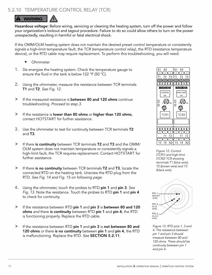
2. Using the ohmmeter, measure the resistance between TCR terminals O1 and O2. See Fig. 12.
h If the measured resistance is between 80 and 120 ohms continue troubleshooting. Proceed to step 3.
h If the resistance is lower than 80 ohms or higher than 120 ohms, contact HOTSTART for further assistance.
3. Use the ohmmeter to test for continuity between TCR terminals O2 and O3.
h If there is continuity between TCR terminals O2 and O3 and the OMM/OLM system does not maintain temperature or consistently signals a high-limit fault, the TCR requires replacement. Contact HOTSTART for further assistance.
h If there is no continuity between TCR terminals O2 and O3, locate the connected RTD on the heating tank. Unscrew the RTD plug from the RTD. See Fig. 14 and Fig. 15 on following page.
4. Using the ohmmeter, touch the probes to RTD pin 1 and pin 3. See Fig. 13. Note the resistance. Touch the probes to RTD pin 1 and pin 4 to check for continuity.
h If the resistance between RTD pin 1 and pin 3 is between 80 and 120 ohms and there is continuity between RTD pin 1 and pin 4, the RTD is functioning properly. Replace the RTD cable.
h If the resistance between RTD pin 1 and pin 3 is not between 80 and 120 ohms or there is no continuity between pin 1 and pin 4, the RTD is malfunctioning. Replace the RTD. See SECOIO 5.2.11.
Figure 13. RTD pins 1, 3 and 4. The resistance between pin 1 and pin 3 should measure between 80 and 120 ohms. There should be continuity between pin 1 and pin 4.
100100 00
11 12 11 12
13 14 A2-13 14 A2-
A3A1A3A1
T1 T2 T3T1 T2 T3
CONTROLOIL
HIGH LIMITOIL
1 2
PIN 1(BROWN WIRE)
PIN 3(BLUE WIRE)
PIN 4(BLACK WIRE)
Figure 12. Control (TCR1) and high-limit (TCR2) TCR showing terminals T1 (blue wire), T2 (brown wire) and T3 (black wire).
17installation & operation manual | omm/olm heating system
5.2.11 RESISTANCE TEMPERATURE DEVICE (RTD)
WARNING!Hazardous voltage: Before wiring, servicing or cleaning the heating system, turn off the power and follow your organization’s lockout and tagout procedure. Failure to do so could allow others to turn on the power unexpectedly, resulting in harmful or fatal electrical shock.
High-limit or control resistance temperature devices (RTDs) sense temperature to either control fluid temperature or protect the system and fluid from overheating. To replace a resistance temperature device (RTD), use the following procedures.
OOE: Before removing and replacing an RTD, ensure the RTD is malfunctioning. See SECOIO 5.2.10.
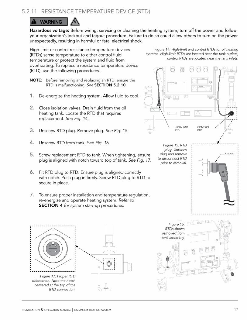
1. De-energize the heating system. Allow fluid to cool.
2. Close isolation valves. Drain fluid from the oil heating tank. Locate the RTD that requires replacement. See Fig. 14.
3. Unscrew RTD plug. Remove plug. See Fig. 15.
4. Unscrew RTD from tank. See Fig. 16.
5. Screw replacement RTD to tank. When tightening, ensure plug is aligned with notch toward top of tank. See Fig. 17.
6. Fit RTD plug to RTD. Ensure plug is aligned correctly with notch. Push plug in firmly. Screw RTD plug to RTD to secure in place.
7. To ensure proper installation and temperature regulation, re-energize and operate heating system. Refer to SECOIO 4 for system start-up procedures.
RTD PLUG
Figure 17. Proper RTD orientation. Note the notch
centered at the top of the RTD connection.
Figure 15. RTD plug. Unscrew
plug and remove to disconnect RTD
prior to removal.
Figure 14. High-limit and control RTDs for oil heating systems. High-limit RTDs are located near the tank outlets;
control RTDs are located near the tank inlets.
HIGH-LIMIT RTD
CONTROL RTD
Figure 16. RTDs shown
removed from tank assembly.
18 installation & operation manual | omm/olm heating system
5.2.12 HEATING TANK/ELEMENT
WARNING!Hazardous voltage: Before wiring, servicing or cleaning the heating system, turn off the power and follow your organization’s lockout and tagout procedure. Failure to do so could allow others to turn on the power unexpectedly, resulting in harmful or fatal electrical shock.
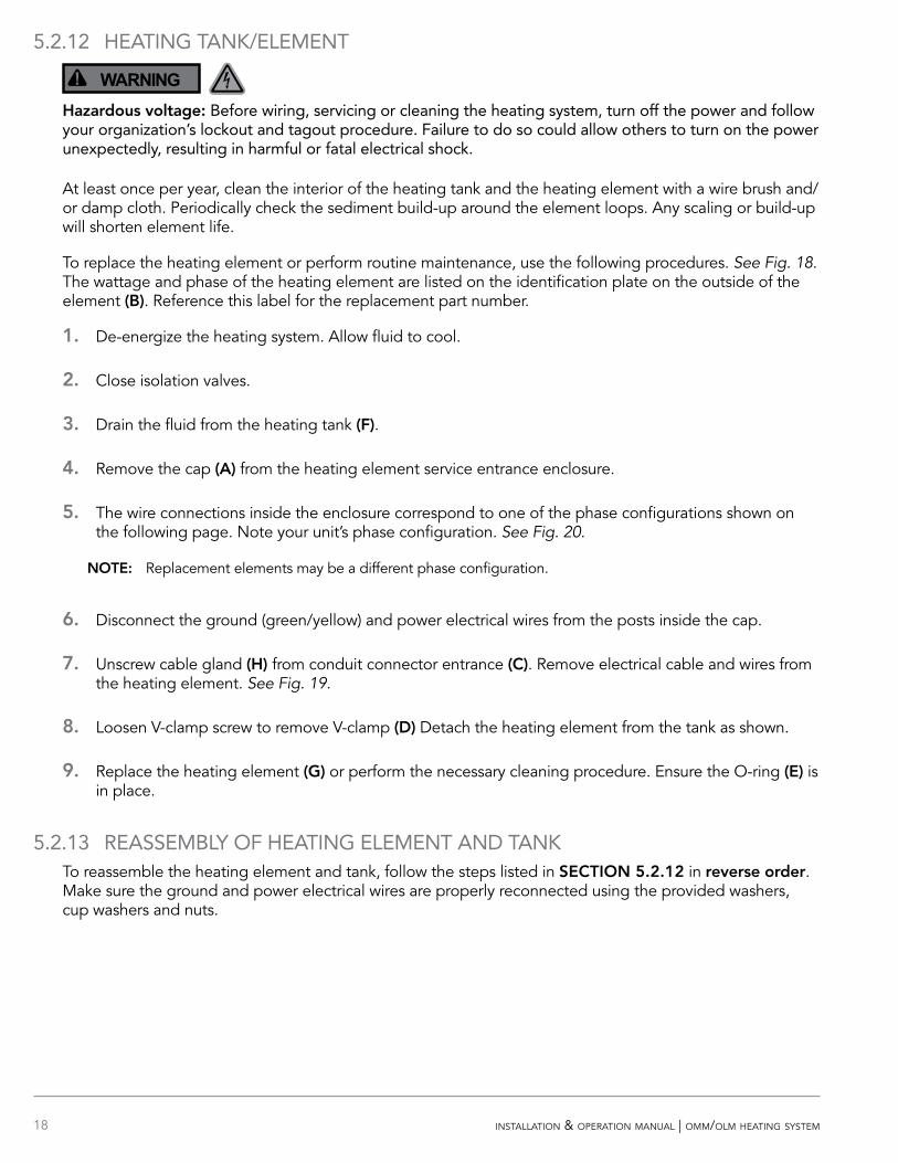
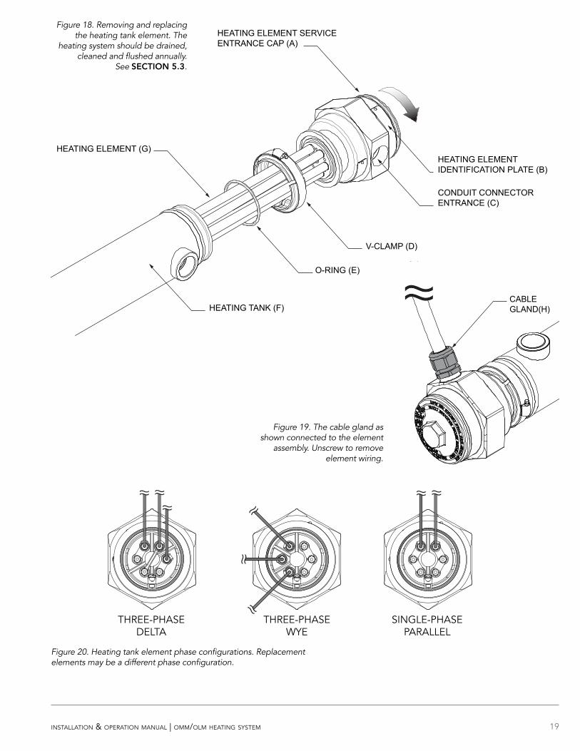
At least once per year, clean the interior of the heating tank and the heating element with a wire brush and/or damp cloth. Periodically check the sediment build-up around the element loops. Any scaling or build-up will shorten element life.
To replace the heating element or perform routine maintenance, use the following procedures. See Fig. 18. The wattage and phase of the heating element are listed on the identification plate on the outside of the element (B). Reference this label for the replacement part number.
1. De-energize the heating system. Allow fluid to cool.
2. Close isolation valves.
3. Drain the fluid from the heating tank (F).
4. Remove the cap (A) from the heating element service entrance enclosure.
5. The wire connections inside the enclosure correspond to one of the phase configurations shown on the following page. Note your unit’s phase configuration. See Fig. 20.
OOE: Replacement elements may be a different phase configuration.
6. Disconnect the ground (green/yellow) and power electrical wires from the posts inside the cap.
7. Unscrew cable gland (H) from conduit connector entrance (C). Remove electrical cable and wires from the heating element. See Fig. 19.
8. Loosen V-clamp screw to remove V-clamp (D) Detach the heating element from the tank as shown.
9. Replace the heating element (G) or perform the necessary cleaning procedure. Ensure the O-ring (E) is in place.
5.2.13 REASSEMBLY OF HEATING ELEMENT AND TANKTo reassemble the heating element and tank, follow the steps listed in SECOIO 5.2.12 in reverse order. Make sure the ground and power electrical wires are properly reconnected using the provided washers, cup washers and nuts.
19installation & operation manual | omm/olm heating system
THREE-PHASEDELTA
THREE-PHASEWYE
SINGLE-PHASEPARALLEL
SINGLE-PHASESERIES
Figure 20. Heating tank element phase configurations. Replacement elements may be a different phase configuration.
HEATING ELEMENT SERVICE ENTRANCE CAP (A)
HEATING ELEMENT IDENTIFICATION PLATE (B)
CONDUIT CONNECTOR ENTRANCE (C)
V-CLAMP (D)
O-RING (E)
HEATING ELEMENT (G)
HEATING TANK (F)
Figure 18. Removing and replacing the heating tank element. The
heating system should be drained, cleaned and flushed annually.
See SECOIO 5.3.
CABLEGLAND(H)
Figure 19. The cable gland as shown connected to the element
assembly. Unscrew to remove element wiring.
20 installation & operation manual | omm/olm heating system
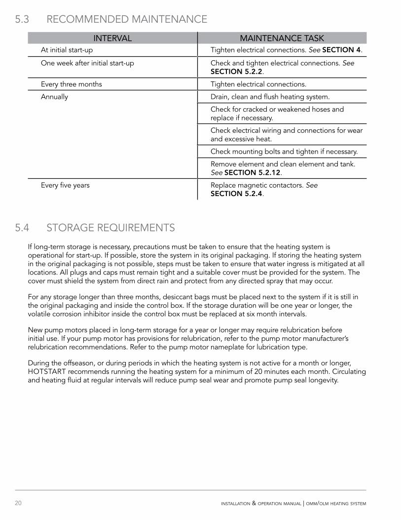
5.3 RECOMMENDED MAINTENANCE
INTERVAL MAINTENANCE TASKAt initial start-up Tighten electrical connections. See SECOIO 4.
One week after initial start-up Check and tighten electrical connections. See SECOIO 5.2.2.
Every three months Tighten electrical connections.
Annually Drain, clean and flush heating system.
Check for cracked or weakened hoses and replace if necessary.
Check electrical wiring and connections for wear and excessive heat.
Check mounting bolts and tighten if necessary.
Remove element and clean element and tank. See SECOIO 5.2.12.
Every five years Replace magnetic contactors. See SECOIO 5.2.4.
5.4 STORAGE REQUIREMENTS
If long-term storage is necessary, precautions must be taken to ensure that the heating system is operational for start-up. If possible, store the system in its original packaging. If storing the heating system in the original packaging is not possible, steps must be taken to ensure that water ingress is mitigated at all locations. All plugs and caps must remain tight and a suitable cover must be provided for the system. The cover must shield the system from direct rain and protect from any directed spray that may occur.
For any storage longer than three months, desiccant bags must be placed next to the system if it is still in the original packaging and inside the control box. If the storage duration will be one year or longer, the volatile corrosion inhibitor inside the control box must be replaced at six month intervals.
New pump motors placed in long-term storage for a year or longer may require relubrication before initial use. If your pump motor has provisions for relubrication, refer to the pump motor manufacturer’s relubrication recommendations. Refer to the pump motor nameplate for lubrication type.
During the offseason, or during periods in which the heating system is not active for a month or longer, HOTSTART recommends running the heating system for a minimum of 20 minutes each month. Circulating and heating fluid at regular intervals will reduce pump seal wear and promote pump seal longevity.
21installation & operation manual | omm/olm heating system
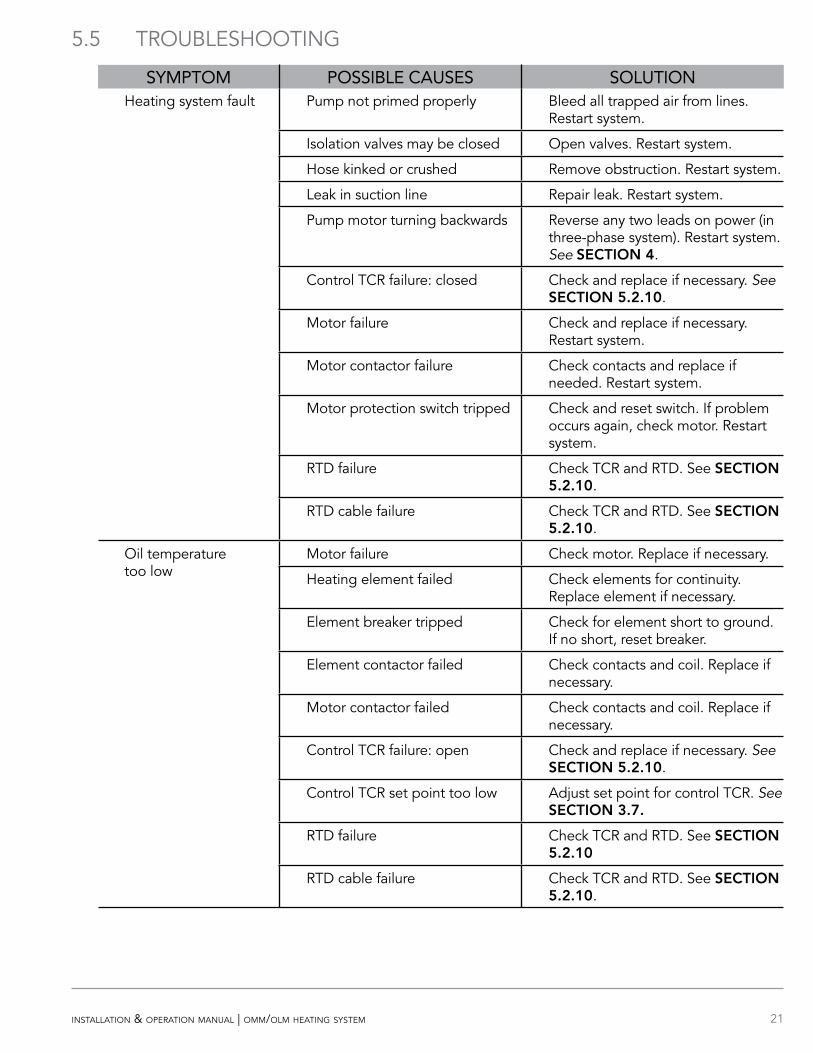
5.5 TROUBLESHOOTING
SYMPTOM POSSIBLE CAUSES SOLUTIONHeating system fault Pump not primed properly Bleed all trapped air from lines.
Restart system.
Isolation valves may be closed Open valves. Restart system.
Hose kinked or crushed Remove obstruction. Restart system.
Leak in suction line Repair leak. Restart system.
Pump motor turning backwards Reverse any two leads on power (in three-phase system). Restart system. See SECOIO 4.
Control TCR failure: closed Check and replace if necessary. See SECOIO 5.2.10.
Motor failure Check and replace if necessary. Restart system.
Motor contactor failure Check contacts and replace if needed. Restart system.
Motor protection switch tripped Check and reset switch. If problem occurs again, check motor. Restart system.
RTD failure Check TCR and RTD. See SECOIO 5.2.10.
RTD cable failure Check TCR and RTD. See SECOIO 5.2.10.
Oil temperature too low
Motor failure Check motor. Replace if necessary.
Heating element failed Check elements for continuity. Replace element if necessary.
Element breaker tripped Check for element short to ground. If no short, reset breaker.
Element contactor failed Check contacts and coil. Replace if necessary.
Motor contactor failed Check contacts and coil. Replace if necessary.
Control TCR failure: open Check and replace if necessary. See SECOIO 5.2.10.
Control TCR set point too low Adjust set point for control TCR. See SECOIO 3.7.
RTD failure Check TCR and RTD. See SECOIO 5.2.10
RTD cable failure Check TCR and RTD. See SECOIO 5.2.10.