Embed Size (px)
Citation preview
DOC-1314 Rev: 20th October 2017
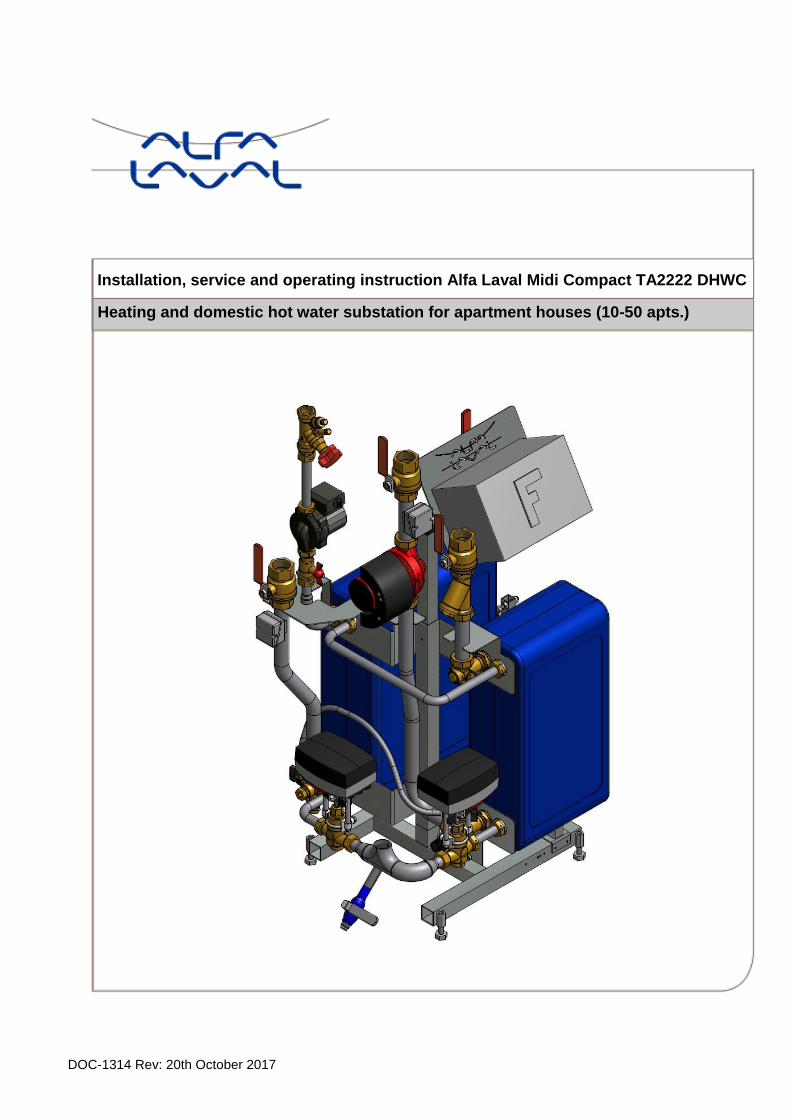
Installation, service and operating instruction Alfa Laval Midi Compact TA2222 DHWC
Heating and domestic hot water substation for apartment houses (10-50 apts.)

Alfa Laval Midi Compact Installation, service and operating instruction
1
Contents 1 General .................................................................................................................................. 4 1.1 Comfort ......................................................................................................................................................4 1.2 Installation .................................................................................................................................................4 1.3 Long-term security .....................................................................................................................................4 1.4 CE-marking ................................................................................................................................................4 1.5 Product overview Midi Compact TA2222 ..................................................................................................5 1.6 Product overview Midi Compact TA2222 with vertical metering ...............................................................6 1.7 Product overview Midi Compact TA2222 with horizontal metering ...........................................................7
2 Operating instructions .......................................................................................................... 8 2.1 Operation ...................................................................................................................................................8 2.2 Safety equipment/inspection .....................................................................................................................8
3 Installation ............................................................................................................................. 9 3.1 Unpacking ..................................................................................................................................................9 3.2 Preparation ................................................................................................................................................9 3.3 Mounting ....................................................................................................................................................9 3.4 Adjustments and settings for start up ..................................................................................................... 10 3.5 Dismantlement........................................................................................................................................ 10 3.6 Commissioning advice ........................................................................................................................... 10 3.7 Measure sketch Midi Compact ............................................................................................................... 11 3.8 Measure sketch Midi Compact with vertical metering ............................................................................ 12 3.9 Measure sketch Midi Compact with horizontal metering ........................................................................ 13
4 Control Center TAC2222 ..................................................................................................... 14 4.1 Flow adjustment ..................................................................................................................................... 14 4.1.1 Control curve ..................................................................................................................................... 14 4.1.2 Automatically adjusting the control curve .......................................................................................... 14 4.1.3 Damped outdoor temperature ........................................................................................................... 14 4.2 Time controlled operation ....................................................................................................................... 15 4.2.1 Control watch .................................................................................................................................... 15 4.2.2 Sliding night time lowering ................................................................................................................ 15 4.2.3 Morning heating ................................................................................................................................. 15 4.2.4 Morning increase ............................................................................................................................... 15 4.2.5 Monday effect .................................................................................................................................... 16 4.3 Hot water drain ....................................................................................................................................... 16 4.4 Pump controlling ..................................................................................................................................... 16 4.4.1 Frost protection ................................................................................................................................. 16 4.4.2 Pump exercise function ..................................................................................................................... 16 4.5 Alerts ...................................................................................................................................................... 16 4.6 Voltage failure......................................................................................................................................... 16 4.7 Maintenance ........................................................................................................................................... 16
5 User instructions operator control panel TAC2222 .......................................................... 17 5.1 Read of temperatures ............................................................................................................................. 18 5.2 Setting the temperature .......................................................................................................................... 18 5.3 Set time program for night time decrease .............................................................................................. 19 5.4 Adjust the controller curve ...................................................................................................................... 20 5.5 Read alarm message ............................................................................................................................. 20 5.6 Set operating mode ................................................................................................................................ 20 5.7 Set time .................................................................................................................................................. 20 5.8 Return temperature limitation ................................................................................................................. 21 5.9 Parameters table .................................................................................................................................... 22
6 Troubleshooting .................................................................................................................. 23 6.1 Fault indication for TA2222 .................................................................................................................... 23 6.2 Fault codes chart Magna pump .............................................................................................................. 24
7 Electrical installation .......................................................................................................... 25 7.1 General ................................................................................................................................................... 25 7.2 Installation of outdoor temperature sensor ............................................................................................. 25 7.3 Electrical circuit diagram EU .................................................................................................................. 26

Alfa Laval Midi Compact Installation, service and operating instruction
2
8 Schematic diagram, main components ............................................................................. 27 8.1 Midi Compact .......................................................................................................................................... 27 8.2 Midi Compact with vertical metering....................................................................................................... 28 8.3 Midi Compact with horizontal metering .................................................................................................. 29
9 Pump settings and pump capacity .................................................................................... 30 9.1 General ................................................................................................................................................... 30 9.2 DHWC pump Grundfos UPSO 15-55, capacity ...................................................................................... 30 9.3 Heating circuit Grundfos Magna 25-100, settings and capacity ............................................................. 31 9.3.1 Control modes ................................................................................................................................... 31 9.3.2 Selection of control mode .................................................................................................................. 33 9.3.3 Maximum or minimum curve duty ..................................................................................................... 34 9.3.4 Control mode setting ......................................................................................................................... 35 9.3.5 Set point setting ................................................................................................................................. 36 9.3.6 Setting to maximum curve duty ......................................................................................................... 36 9.3.7 Setting to minimum curve duty .......................................................................................................... 37 9.3.8 Starting and stopping pump .............................................................................................................. 37 9.3.9 Resetting of fault indications ............................................................................................................. 37
10 Service instructions ............................................................................................................ 38
11 Maintenance and repairs .................................................................................................... 45 11.1 Change the radiator and DHWC pump .................................................................................................. 45 11.2 Change the heating actuator .................................................................................................................. 45 11.3 Change the heating valve ....................................................................................................................... 46 11.4 Change the hot water actuator ............................................................................................................... 46 11.5 Change the hot water valve .................................................................................................................... 47 11.6 Change the heat temperature sensor .................................................................................................... 47 11.7 Change the outdoor temperature sensor ............................................................................................... 47
12 Options ................................................................................................................................ 48 12.1 3-point HB metering ............................................................................................................................... 48 12.2 4-point HB metering ............................................................................................................................... 48 12.3 GENI module .......................................................................................................................................... 49
13 Operation data and capacity .............................................................................................. 50 13.1 Operation data Midi Compact 80............................................................................................................ 50 13.2 Operation data Midi Compact 100.......................................................................................................... 51 13.3 Operation data Midi Compact 160.......................................................................................................... 52 13.4 Operation data Midi Compact 200.......................................................................................................... 53 13.5 Technical data ........................................................................................................................................ 53
14 Declaration of conformity art 4.3 ....................................................................................... 54
15 Declaration of conformity Cat 1 ......................................................................................... 55
Alfa Laval Midi Compact Installation, service and operating instruction
3
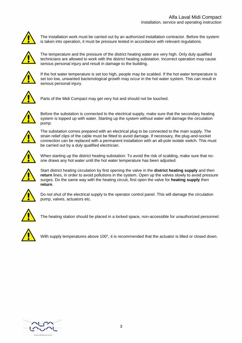
The installation work must be carried out by an authorized installation contractor. Before the system is taken into operation, it must be pressure tested in accordance with relevant regulations.
The temperature and the pressure of the district heating water are very high. Only duly qualified technicians are allowed to work with the district heating substation. Incorrect operation may cause serious personal injury and result in damage to the building.
If the hot water temperature is set too high, people may be scalded. If the hot water temperature is set too low, unwanted bacteriological growth may occur in the hot water system. This can result in serious personal injury.
Parts of the Midi Compact may get very hot and should not be touched.
Before the substation is connected to the electrical supply, make sure that the secondary heating system is topped up with water. Starting up the system without water will damage the circulation pump.
The substation comes prepared with an electrical plug to be connected to the main supply. The strain relief clips of the cable must be fitted to avoid damage. If necessary, the plug-and-socket connection can be replaced with a permanent installation with an all-pole isolate switch. This must be carried out by a duly qualified electrician.
When starting up the district heating substation: To avoid the risk of scalding, make sure that no-one draws any hot water until the hot water temperature has been adjusted.
Start district heating circulation by first opening the valve in the district heating supply and then return lines, in order to avoid pollutions in the system. Open up the valves slowly to avoid pressure surges. Do the same way with the heating circuit, first open the valve for heating supply then return.
Do not shut of the electrical supply to the operator control panel. This will damage the circulation pump, valves, actuators etc.
The heating station should be placed in a locked space, non-accessible for unauthorized personnel.
With supply temperatures above 100°, it is recommended that the actuator is tilted or closed down.
Alfa Laval Midi Compact Installation, service and operating instruction
4
1 General Alfa Laval Midi Compact is a complete, ready-to-install heating network substation for heating and hot water. It is designed for buildings with a primary connection to a heating network. Alfa Laval has years of experience in heating network technology and has developed Midi Compact with well-planned pipe work and with all components easily accessible for inspection and possible future servicing.
1.1 Comfort
Midi Compact has fully-automatic temperature control for heating and hot water. The heating is controlled in relation to desired room temperature. The hot water is controlled and maintained at the desired temperature.
1.2 Installation
Well planned pipe work and readymade electrical wiring make installation very simple. A pre-programmed controller and plug-and-socket connection provide further simplification, so that the substation can be started without delay. The Midi Compact is designed to be placed on the floor. Before installation this manual must be read.
1.3 Long-term security
All the plates and pipes in the heat exchanger are made of acid-resistant stainless steel for long life. All components are adjusted together and undergo thorough function testing in accordance with Alfa Laval’s ISO 9001:2008 quality assurance system. For future servicing requirements, all components are easily accessible and individually replaceable.
1.4 CE-marking
Midi Compact is CE-marked to certify that the substation conforms to international safety regulations. To maintain the validity of the CE marking, only identical replacement parts must be used.
Alfa Laval Midi Compact Installation, service and operating instruction
5
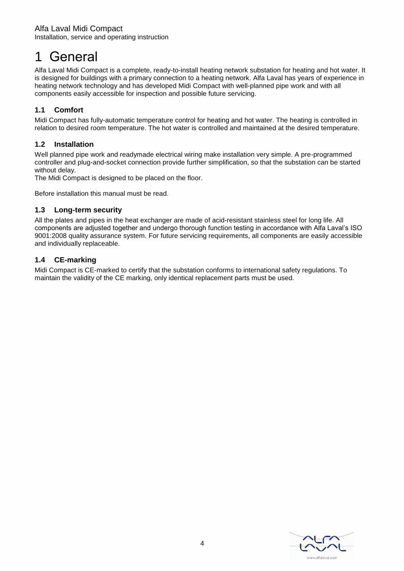
1.5 Product overview Midi Compact TA2222
Picture 1
Picture 2
1 Heat exchanger heat 20 Topping up
2 Heat exchanger DHW 21 Hose
3 Control center 22 Draining valve, heat supply
4 Control valve, heating 23 Shut off valve, heat supply
5 Actuator, heating 24 Pump, heating
6 Control valve, DHW 25 Safety valve, heating
7 Actuator, DHW 26 Shut off valve, heat return
8 Temp.sensor, outdoor 27 Strainer, heat return
9 Temp.sensor, heating Supply 28 Connection, expansion vessel
10 Temp.sensor, DHW Supply 29 Draining valve, DH-Supply
11 Shut off valve, DHW 36 Temp.sensor heating return
12 Balancing valve, DHWC 37 DH Return
13 Pump, DHWC 38 CW
14 None return valve, DHWC 39 DHWC
15 Shut off valve, DHWC 40 DHW
16 Shut off valve, CW 41 DH supply
17 None return valve, CW 42 Heat Supply
18 Safety valve, CW 43 Heat Return
19 Draining valve, DH-Supply
Alfa Laval Midi Compact Installation, service and operating instruction
6
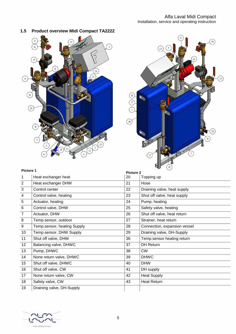
1.6 Product overview Midi Compact TA2222 with vertical metering
Picture 3
Picture 4
1 Heat exchanger heat 22 Draining valve, heat supply
2 Heat exchanger DHW 23 Shut off valve, heat supply
3 Control center 24 Pump, heating
4 Control valve, heating 25 Safety valve, heating
5 Actuator, heating 26 Shut off valve, heat return
6 Control valve, DHW 27 Strainer, heat return
7 Actuator, DHW 28 Connection, expansion vessel
8 Temp.sensor, outdoor 29 Draining valve, DH-Supply
9 Temp.sensor, heating Supply 30 Strainer, DH-Supply
10 Temp.sensor, DHW Supply 31 Heat meter dummy
11 Shut off valve, DHW 32 Connection energy meter sensor primary supply
12 Balancing valve, DHWC 33 Connection energy meter sensor primary return
13 Pump, DHWC 36 Temp.sensor heating return
14 None return valve, DHWC 37 DH Return
15 Shut off valve, DHWC 38 CW
16 Shut off valve, CW 39 DHWC
17 None return valve, CW 40 DHW
18 Safety valve, CW 41 DH supply
19 Draining valve, DH-Supply 42 Heat Supply
20 Topping up 43 Heat Return
21 Hose
Alfa Laval Midi Compact Installation, service and operating instruction
7
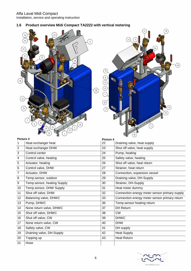
1.7 Product overview Midi Compact TA2222 with horizontal metering
Picture 5
Picture 6
1 Heat exchanger heat 23 Shut off valve, heat supply
2 Heat exchanger DHW 24 Pump, heating
3 Control center 25 Safety valve, heating
4 Control valve, heating 26 Shut off valve, heat return
5 Actuator, heating 27 Strainer, heat return
6 Control valve, DHW 28 Connection, expansion vessel
7 Actuator, DHW 29 Draining valve, DH-Supply
8 Temp.sensor, outdoor 30 Strainer, DH-Supply
9 Temp.sensor, heating Supply 31 Heat meter dummy
10 Temp.sensor, DHW Supply 32 Connection energy meter sensor primary supply
11 Shut off valve, DHW 33 Connection energy meter sensor primary return
12 Balancing valve, DHWC 34 Connection 3-point HB metering
13 Pump, DHWC 35 Pressure gauge connection
14 None return valve, DHWC 36 Temp.sensor heating return
15 Shut off valve, DHWC 37 DH Return
16 Shut off valve, CW 38 CW
17 None return valve, CW 39 DHWC
18 Safety valve, CW 40 DHW
19 Draining valve, DH-Supply 41 DH supply
20 Topping up 42 Heat Supply
21 Hose 43 Heat Return
22 Draining valve, heat supply
Alfa Laval Midi Compact Installation, service and operating instruction
8
2 Operating instructions
2.1 Operation
The temperature and pressure of the incoming heating network water from the culvert network are very high. For this reason, only the heat from this water is used. The heating network water does not enter the heating and hot water systems of the building. The heat from the heating network water is transferred to the heating and hot water systems of the building in the heat exchangers. The heat is transferred through thin plates of acid-resistant stainless steel which keep the heating network water completely separated from the systems in the building. Midi Compact has automatic temperature control for heating and hot water. The heating circuit is controlled in relation to outdoor temperature (option) and/or desired room temperature by means of a controller and temperature sensor. When no heat is needed, the circulation pump in the heating circuit stops automatically, but is started regularly to make sure that it does not seize up during long idle periods. The hot water temperature is controlled by a temperature control system which is set to about 55 ºC. After adjustment, the Midi Compact operates completely automatically. However, in hard water areas it is advisable to be attentive and to remedy any faults in good time if the temperature of the hot water is too high; otherwise the risk of lime deposits in the heat exchanger may increase.
2.2 Safety equipment/inspection
• Daily inspection to check for leaks from pipes or components.
• Weekly inspection to make sure that the operation of the heating and hot water control systems is stable and that the temperature does not fluctuate. Temperature hunting causes unnecessary wear of valves, actuators and heat exchangers.
• Every three months check the safety valves and the pressure in the heating system. To check the operation of a safety valve, turn its wheel until water escapes from the waste pipe of the valve, then close the wheel quickly. Occasionally a safety valve may open automatically to release excess pressure. After a safety valve has been open it is important that it closes properly and does not drip. Hot water temperature in apartments or one family houses can be set to about 55°C. If the temperature is set too high, there is a risk of scalding. Setting the hot water temperature too low may result in unwanted bacteriological growth in the hot water system. For setting and (if necessary) fine adjustment of the heating and hot water temperatures, see chapter 4 Control Center TAC2222. The heating system is topped up via the topping up valve. Be sure to close the valve when the correct pressure is reached. The water used to top up the system contains oxygen and may cause corrosion in the system. For this reason, the system should be topped up as seldom as possible, at most once If a joining must be loosened and then re-installed, for example when installing the substation or when replacing a filter unit, the joining gaskets should be exchanged to prevent leaks.
Alfa Laval Midi Compact Installation, service and operating instruction
9
3 Installation
3.1 Unpacking
• Remove the transport packaging and check that the product has not been damaged in transit and that the consignment agrees with the specifications.
• When lifting the unit, take care not to apply stress to pipes and heat exchangers as this may weaken them. Lift the unit in the frame; avoid lifting the unit by holding the heat exchangers. Use pallet lift where applicable, if using back straps these should be attached to the substructure of the substation. Note: Risk of injury lifting heavy objects.
3.2 Preparation
• Choose a suitable installation area in accordance with official regulations. The system may generate sounds during operation caused by pumps, regulators systems, flows etc. This should be taken into consideration during installation of the unit, so that possible operational sounds affect the surroundings as little as possible.
• Check the applicable regulations of the district heating supplier. The available differential pressure should be at least 100 kPa and at most 600 kPa. Where the differential pressure is higher, a differential pressure controller should be added to the installation.
• Flush heating and hot water systems.
3.3 Mounting
• Place the substation so that connections, adjustment equipment and safety valves are easily accessible.
• Mount the shutoff valves on district heating supply and return. Shutoff valves are not supplied.
• Connect the pipe works to the connection points, see 3.7-3.9.
• When executing hot work on or close by the substation, all incendiary components should be demounted and removed.
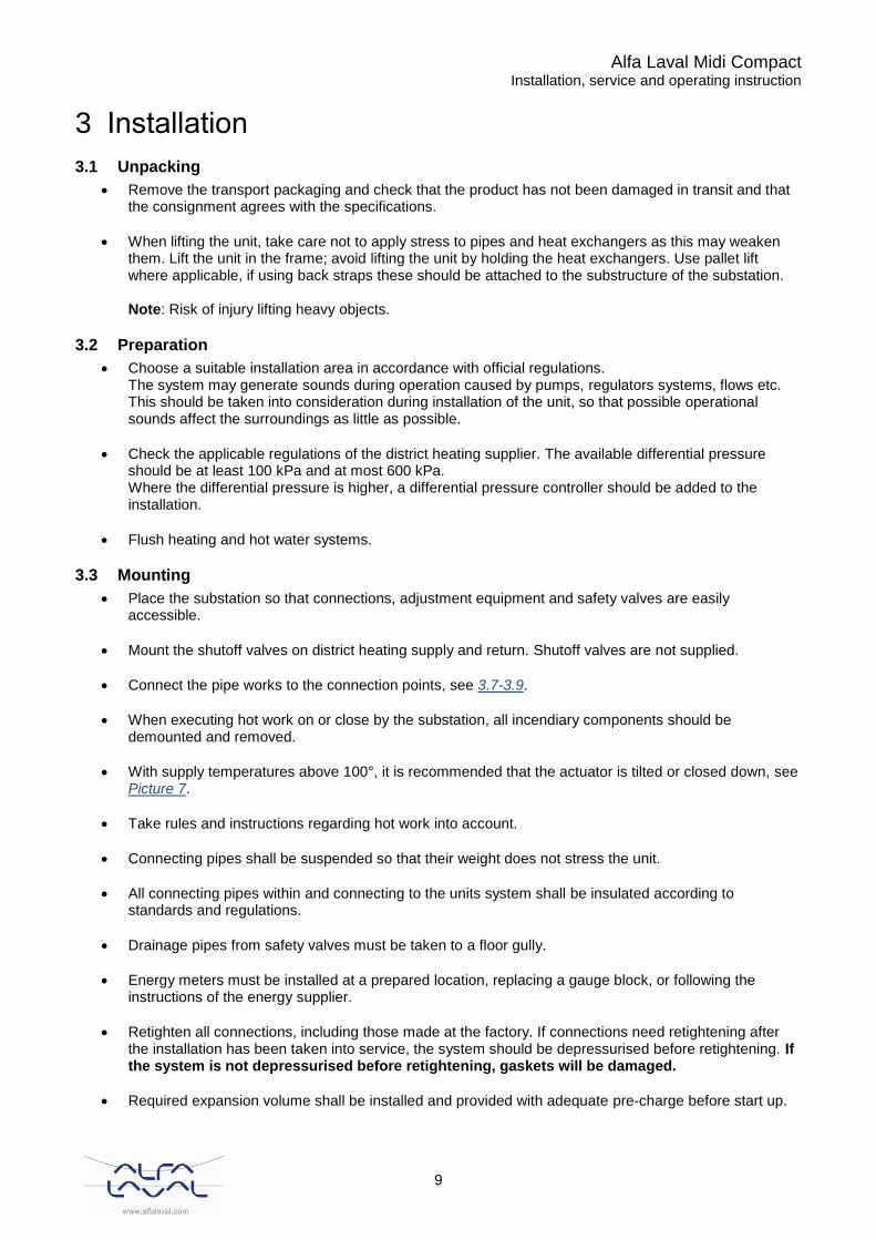
• With supply temperatures above 100°, it is recommended that the actuator is tilted or closed down, see Picture 7.
• Take rules and instructions regarding hot work into account.
• Connecting pipes shall be suspended so that their weight does not stress the unit.
• All connecting pipes within and connecting to the units system shall be insulated according to standards and regulations.
• Drainage pipes from safety valves must be taken to a floor gully.
• Energy meters must be installed at a prepared location, replacing a gauge block, or following the instructions of the energy supplier.
• Retighten all connections, including those made at the factory. If connections need retightening after the installation has been taken into service, the system should be depressurised before retightening. If the system is not depressurised before retightening, gaskets will be damaged.
• Required expansion volume shall be installed and provided with adequate pre-charge before start up.
Alfa Laval Midi Compact Installation, service and operating instruction
10
• Remount plugs in drain valves after possible draining of circuit.
• Mount the outdoor temperature sensor on the north side of the building, 2 meters above the ground, or higher. For installation of the outdoor temperature sensor, see 7.2.
Picture 7
3.4 Adjustments and settings for start up
• Open up incoming cold water supply and fill the service water and heating circuits, bleeding off any trapped air.
• Check the operation and opening pressures of the safety valves.
• Adjust the hot water temperature by having a hot water tap open at normal flow rate for a time. Measure the temperature at the draw-off point with a thermometer. The temperature should be approximately 55°C. It takes about 20 seconds to get stable tap water temperature. See troubleshooting chart for adjusting hot water temperature. NOTE: Make sure that no cold water is mixed with hot water while making this adjustment.
• Start the heating circulation pump at the strongest flow setting during some minutes. The pressure should be at least 1000 kPa during winter and at least 600kPA during summer.
• Set the pump capacity of the heating circulation pump and the DHWC-pump according to chapter 9 Pump settings and pump capacity. Use the lowest setting that manages the heating demand for best electrical efficiency.
• Make any necessary adjustment of the heating curve of the control and regulating equipment. Information about the controller can be found in this document.
• Set time, date and hot water temperature on the adjustment center.
• The property owner must be informed on how to operate, adjust and maintain the unit. It is overly important to inform about the safety systems and the risks associated with the high pressure and temperature of the district heating systems water supply.
3.5 Dismantlement
When the time comes for the substation to be dismantled and scrapped it must be disposed of in the correct manner in accordance with local or national regulations.
3.6 Commissioning advice
The controller has been set at the factory. If any function needs tuning, values can be changed with reference to this manual for parameter setting. Initially, the commissioning process should be carried out with the factory settings. The parameter settings need tuning only if the district heat terminal does not function accordingly.
Alfa Laval Midi Compact Installation, service and operating instruction
11
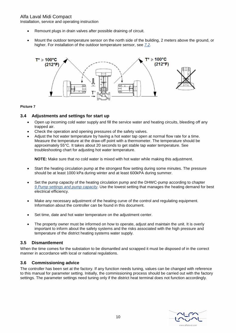
3.7 Measure sketch Midi Compact
Picture 8
Alfa Laval Midi Compact Installation, service and operating instruction
12
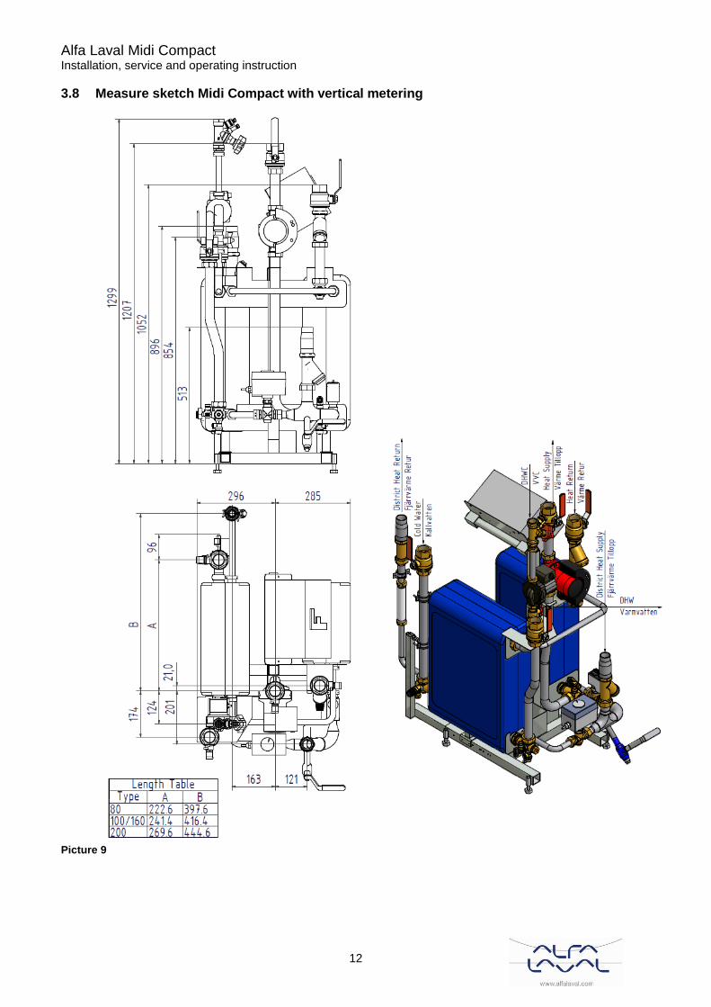
3.8 Measure sketch Midi Compact with vertical metering
Picture 9

Alfa Laval Midi Compact Installation, service and operating instruction
13
3.9 Measure sketch Midi Compact with horizontal metering
Picture 10
Alfa Laval Midi Compact Installation, service and operating instruction
14
4 Control Center TAC2222
4.1 Flow adjustment
4.1.1 Control curve
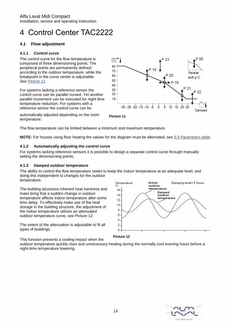
The control curve for the flow temperature is composed of three dimensioning points. The peripheral points are permanently defined according to the outdoor temperature, while the breakpoint in the curve center is adjustable. See Picture 11. For systems lacking a reference sensor the control curve can be parallel moved. Yet another parallel movement can be executed for night time temperature reduction. For systems with a reference sensor the control curve can be
automatically adjusted depending on the room temperature. The flow temperature can be limited between a minimum and maximum temperature. NOTE: For houses using floor heating the values for the diagram must be alternated, see 5.9 Parameters table.
4.1.2 Automatically adjusting the control curve
For systems lacking reference sensors it is possible to design a separate control curve through manually setting the dimensioning points.
4.1.3 Damped outdoor temperature
The ability to control the flow temperature seeks to keep the indoor temperature at an adequate level, and doing this independent to changes for the outdoor temperature. The building structures inherent heat inertness and mass bring that a sudden change in outdoor temperature affects indoor temperature after some time delay. To effectively make use of the heat storage in the building structure, the adjustment of the indoor temperature utilizes an attenuated outdoor temperature curve, see Picture 12. The extent of the attenuation is adjustable to fit all types of buildings.
This function prevents a cooling impact when the outdoor temperature quickly rises and unnecessary heating during the normally cool evening hours before a night-time temperature lowering.
Picture 11
Picture 12
Alfa Laval Midi Compact Installation, service and operating instruction
15
4.2 Time controlled operation
4.2.1 Control watch
The control watch has two week-programs. One program controls the night-time lowering of the heating. The other controls the night-time lowering of the warm water drain and other optional equipment, i.e. the hot water circulation pump. Furthermore, six optional weekend intervals can be programmed up to a year in advance.
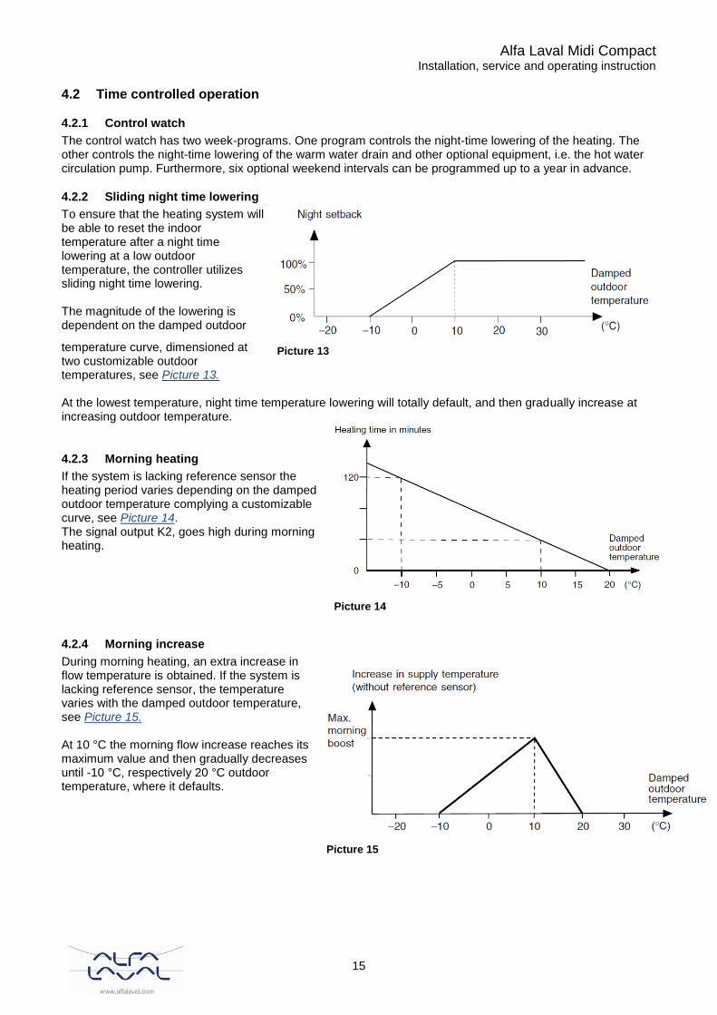
4.2.2 Sliding night time lowering
To ensure that the heating system will be able to reset the indoor temperature after a night time lowering at a low outdoor temperature, the controller utilizes sliding night time lowering. The magnitude of the lowering is dependent on the damped outdoor
temperature curve, dimensioned at two customizable outdoor temperatures, see Picture 13. At the lowest temperature, night time temperature lowering will totally default, and then gradually increase at increasing outdoor temperature.
4.2.3 Morning heating
If the system is lacking reference sensor the heating period varies depending on the damped outdoor temperature complying a customizable curve, see Picture 14. The signal output K2, goes high during morning heating.
4.2.4 Morning increase
During morning heating, an extra increase in flow temperature is obtained. If the system is lacking reference sensor, the temperature varies with the damped outdoor temperature, see Picture 15. At 10 °C the morning flow increase reaches its maximum value and then gradually decreases until -10 °C, respectively 20 °C outdoor temperature, where it defaults.
Picture 13
Picture 14
Picture 15
Alfa Laval Midi Compact Installation, service and operating instruction
16
4.2.5 Monday effect
After weekends, when night time operation runs more than 20 hours, the controller can start up heating earlier than what would be compulsory with morning heating. This is done by a percentage addition to the time factor for the curve controlling morning heating.
4.3 Hot water drain
The drain water can be set with separated set points for day and night according to the extra week-program. To ensure stability at low strain, the dead band for the drain water controller is variable. This implies that a larger dead band is used at low strain (for hot water circulation) and a smaller dead band when draining.
4.4 Pump controlling
According to pump controlling logics it means to utilize the buildings accumulated heat as efficiently as possible. Thus, the pump will operate only when an actual heating need exists. The following prerequisites apply:
• The pump is stopped and the controller valve is shut when the calculated flow rate falls below the user defined rate.
• The pump is stopped and the controller valve is shut when the outdoor temperature exceeds the user defined cut-off temperature. The time elapsed before restart after a pump stop can be defined to between 0-12 hours.
When the condition for a pump stop is met, the pump is stopped after a non-adjustable time delay of 5 minutes.
4.4.1 Frost protection
The frost protection function for the pump ensures that the pump always starts and the valve begins to operate when the outdoor temperature is less than +3°C with a hysteresis of 2°C.
4.4.2 Pump exercise function
Every Monday at 12.00, the pump starts automatically to prevent seizure.
4.5 Alerts
The following alert functions exist in the system:
• Deviation alert for the flow rate temperature.
• Deviation alert for hot water drain temperature. Triggered alerts can be observed in the controller display and is reset automatically when the alert cause is restored.
4.6 Voltage failure
The controller keeps all settings for unlimited time lapse. If a voltage failure lasts longer than 48 hours the clock must be manually reset.
4.7 Maintenance
The controller does not need specific maintenance but should be kept clean. However, the controller equipment must be attended regularly, so that plausible errors does not cause over heating or freezing of the circuit lines. The menu window can, when needed, be dried with a moist cloth.
Alfa Laval Midi Compact Installation, service and operating instruction
17
5 User instructions operator control panel TAC2222
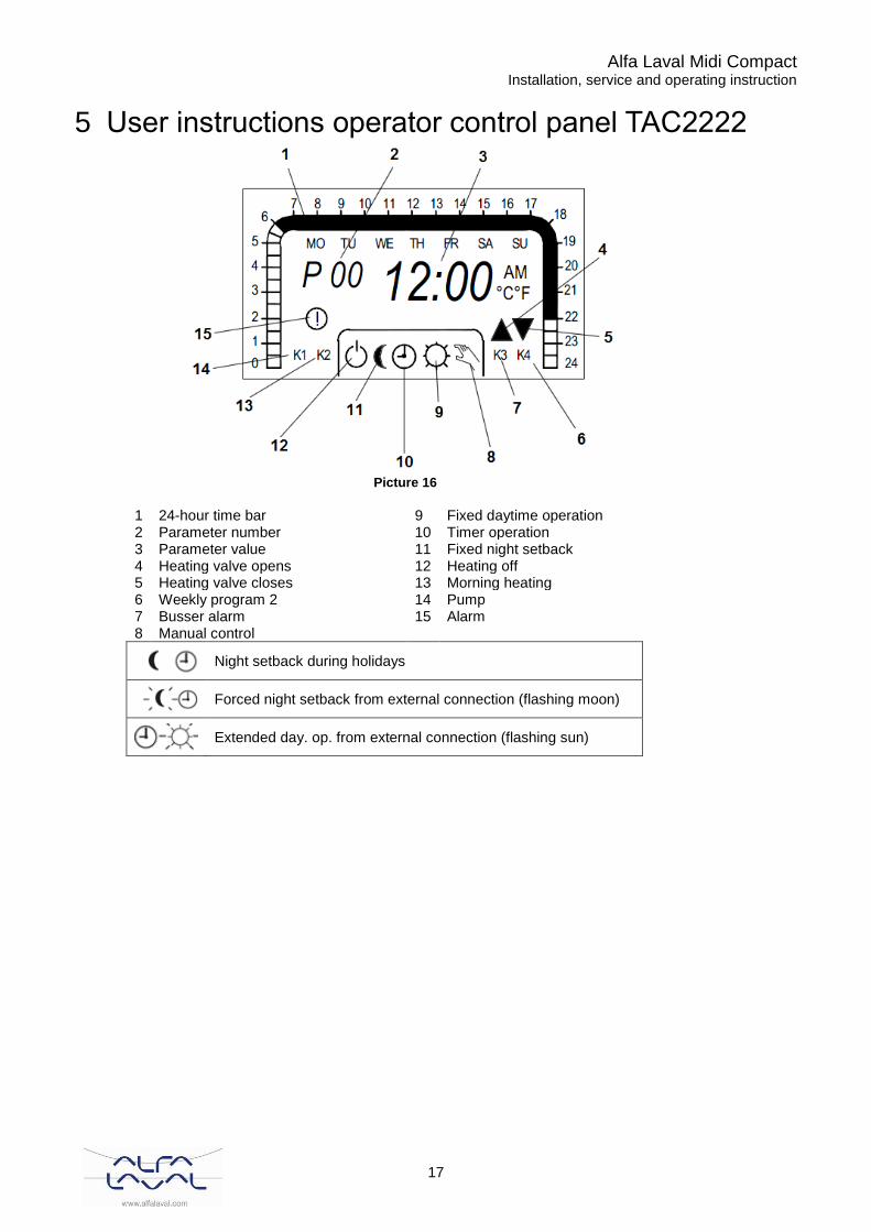
Picture 16
1 24-hour time bar 9 Fixed daytime operation 2 Parameter number 10 Timer operation 3 Parameter value 11 Fixed night setback 4 Heating valve opens 12 Heating off 5 Heating valve closes 13 Morning heating 6 Weekly program 2 14 Pump 7 Busser alarm 15 Alarm 8 Manual control
Night setback during holidays
Forced night setback from external connection (flashing moon)
Extended day. op. from external connection (flashing sun)
Alfa Laval Midi Compact Installation, service and operating instruction
18
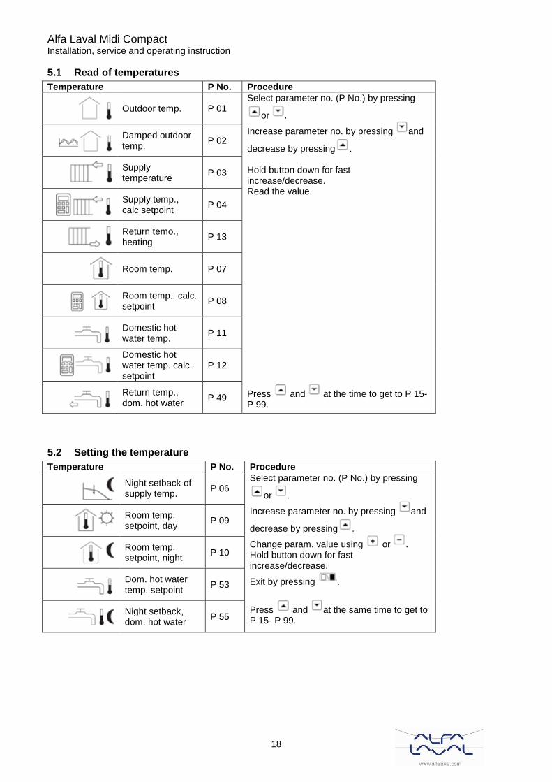
5.1 Read of temperatures
Temperature P No. Procedure
Outdoor temp. P 01
Select parameter no. (P No.) by pressing
or .
Increase parameter no. by pressing and
decrease by pressing . Hold button down for fast increase/decrease. Read the value.
Damped outdoor temp.
P 02
Supply temperature
P 03
Supply temp., calc setpoint
P 04
Return temo., heating
P 13
Room temp. P 07
Room temp., calc. setpoint
P 08
Domestic hot water temp.
P 11
Domestic hot water temp. calc. setpoint
P 12
Return temp., dom. hot water
P 49 Press and at the time to get to P 15- P 99.
5.2 Setting the temperature
Temperature P No. Procedure
Night setback of supply temp.
P 06 Select parameter no. (P No.) by pressing
or .
Increase parameter no. by pressing and
decrease by pressing .
Change param. value using or . Hold button down for fast increase/decrease.
Exit by pressing .
Press and at the same time to get to P 15- P 99.
Room temp. setpoint, day
P 09
Room temp. setpoint, night
P 10
Dom. hot water temp. setpoint
P 53
Night setback, dom. hot water
P 55

Alfa Laval Midi Compact Installation, service and operating instruction
19
5.3 Set time program for night time decrease
Time schedule P No. Procedure
Weekly program for night setback of heating
P 14
1. Select param. no. (P14) using or .
2. Scroll using or . 3. Change half-hour segments by pressing
( = daytime operation).
4. Exit by pressing or .
Reduce heating at holidays
1. Select param. no. P63 using and .
P 63 2. Select holidays (1-6). Go to P64 using
.
P 64
3. Change start date (month.day) using
or .
Go to P65 using
P 65
4. Change end date (mont.day) using
or .
Exit using .
Clear holidays P 63 1. Select the holiday (see above).
P 64 P 65
2. Change start or end date to [month].00
by pressing or .
3. Exit using .
Weekly program for domestic hot water and output K4.
P 61
1. Select parameter no. (P61) using and
.
2. Scroll by pressing or .
3. Change by pressing ( = daytime operation, K4 on).
4. Exit by pressing .

Alfa Laval Midi Compact Installation, service and operating instruction
20
5.4 Adjust the controller curve
Procedure
Select param. No (P No.) by pressing or . Increase param. no. by pressing and
decrease by pressing . Press and at the same time to get to P15-P99. Change the
param. value using or . Hold button down for fast increase / decrease.
Exit by pressing ..
Picture 17
Parallel shift ±°C
5.5 Read alarm message
Cause of the alarm P No. Procedure
Circulation pump P 82
Select parameter no. (P No.) by pressing
or .
Press and at the same time to get to P15 – P99. Read the value. 0 = NO ALARM, 1 = ALARM
Supply temerature P 83
Dom. hot water temperature
P 84
5.6 Set operating mode
Action P No. Procedure
Setting the operating mode: P 00 Change to operating mode required using
or .
Execute by pressing .
Heating off
Fixed night setback
Timer operation
Fixed daytime operation
Manual control
5.7 Set time
Action P No. Procedure
Read off the time P 00 Read hour.minute
Set time P 15 Change hour.minute
Set month and day P 16 Change month.day
Set year P 17 Change year

Alfa Laval Midi Compact Installation, service and operating instruction
21
5.8 Return temperature limitation
The return water temperature can be limited by the controller. The limitation starts when the return temperature is higher than its set max value, then the controller limits the supply temperature. Limitation is variable, i.e. depending on the outdoor temperature according to a separate control curve, with two adjustable curve points.
Picture 18
P nr Parameters Min Max Step Default Comments
P13 Return temperature, heating
0°C 0,3°C Step=0,1 at 2-55°C
P43 Return limitation on/off 0 2 1 1 0=off 1= heating 2* heat+ dom.h.w
P44 Return limit., heating, P band
10°C 200°C 0,5°C 20°C Not if P43=0
P45 Curve point( x0) -30°C 40°C 1°C 40°C Not if P43=0
P46 Curve point (y0) 40°C 120°C 1°C 120°C Not if P43=0
P47 Curve point (x1) -10°C 40°C 1°C 40°C Not if P43=0
P48 Curve point (y1) 10°C 70°C 1°C 70°C Not if P43=0
Alfa Laval Midi Compact Installation, service and operating instruction
22
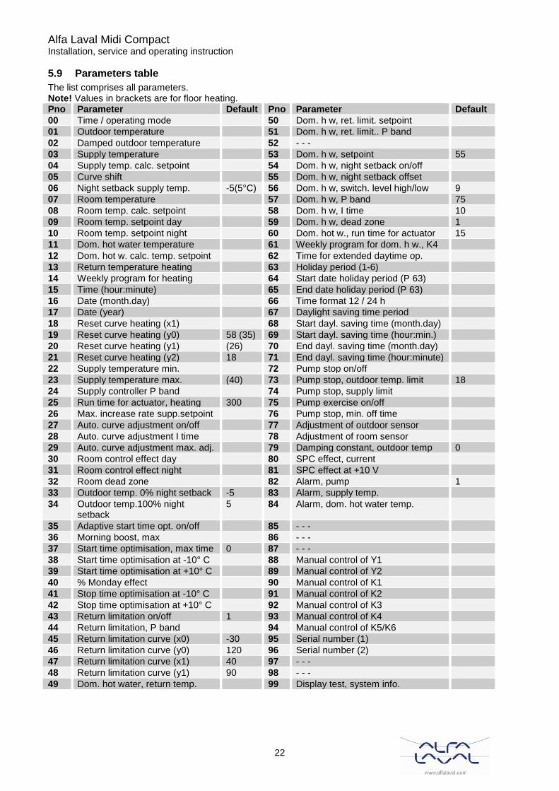
5.9 Parameters table
The list comprises all parameters. Note! Values in brackets are for floor heating. Pno Parameter Default Pno Parameter Default
00 Time / operating mode 50 Dom. h w, ret. limit. setpoint
01 Outdoor temperature 51 Dom. h w, ret. limit.. P band
02 Damped outdoor temperature 52 - - -
03 Supply temperature 53 Dom. h w, setpoint 55
04 Supply temp. calc. setpoint 54 Dom. h w, night setback on/off
05 Curve shift 55 Dom. h w, night setback offset
06 Night setback supply temp. -5(5°C) 56 Dom. h w, switch. level high/low 9
07 Room temperature 57 Dom. h w, P band 75
08 Room temp. calc. setpoint 58 Dom. h w, I time 10
09 Room temp. setpoint day 59 Dom. h w, dead zone 1
10 Room temp. setpoint night 60 Dom. hot w., run time for actuator 15
11 Dom. hot water temperature 61 Weekly program for dom. h w., K4
12 Dom. hot w. calc. temp. setpoint 62 Time for extended daytime op.
13 Return temperature heating 63 Holiday period (1-6)
14 Weekly program for heating 64 Start date holiday period (P 63)
15 Time (hour:minute) 65 End date holiday period (P 63)
16 Date (month.day) 66 Time format 12 / 24 h
17 Date (year) 67 Daylight saving time period
18 Reset curve heating (x1) 68 Start dayl. saving time (month.day)
19 Reset curve heating (y0) 58 (35) 69 Start dayl. saving time (hour:min.)
20 Reset curve heating (y1) (26) 70 End dayl. saving time (month.day)
21 Reset curve heating (y2) 18 71 End dayl. saving time (hour:minute)
22 Supply temperature min. 72 Pump stop on/off
23 Supply temperature max. (40) 73 Pump stop, outdoor temp. limit 18
24 Supply controller P band 74 Pump stop, supply limit
25 Run time for actuator, heating 300 75 Pump exercise on/off
26 Max. increase rate supp.setpoint 76 Pump stop, min. off time
27 Auto. curve adjustment on/off 77 Adjustment of outdoor sensor
28 Auto. curve adjustment I time 78 Adjustment of room sensor
29 Auto. curve adjustment max. adj. 79 Damping constant, outdoor temp 0
30 Room control effect day 80 SPC effect, current
31 Room control effect night 81 SPC effect at +10 V
32 Room dead zone 82 Alarm, pump 1
33 Outdoor temp. 0% night setback -5 83 Alarm, supply temp.
34 Outdoor temp.100% night setback
5 84 Alarm, dom. hot water temp.
35 Adaptive start time opt. on/off 85 - - -
36 Morning boost, max 86 - - -
37 Start time optimisation, max time 0 87 - - -
38 Start time optimisation at -10° C 88 Manual control of Y1
39 Start time optimisation at +10° C 89 Manual control of Y2
40 % Monday effect 90 Manual control of K1
41 Stop time optimisation at -10° C 91 Manual control of K2
42 Stop time optimisation at +10° C 92 Manual control of K3
43 Return limitation on/off 1 93 Manual control of K4
44 Return limitation, P band 94 Manual control of K5/K6
45 Return limitation curve (x0) -30 95 Serial number (1)
46 Return limitation curve (y0) 120 96 Serial number (2)
47 Return limitation curve (x1) 40 97 - - -
48 Return limitation curve (y1) 90 98 - - -
49 Dom. hot water, return temp. 99 Display test, system info.
Alfa Laval Midi Compact Installation, service and operating instruction
23
6 Troubleshooting
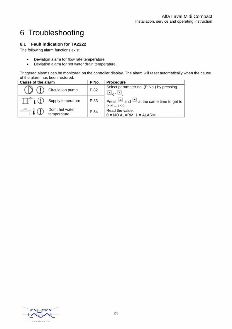
6.1 Fault indication for TA2222
The following alarm functions exist:
• Deviation alarm for flow rate temperature.
• Deviation alarm for hot water drain temperature. Triggered alarms can be monitored on the controller display. The alarm will reset automatically when the cause of the alarm has been restored.
Cause of the alarm P No. Procedure
Circulation pump P 82
Select parameter no. (P No.) by pressing
or .
Press and at the same time to get to P15 – P99. Read the value. 0 = NO ALARM, 1 = ALARM
Supply temerature P 83
Dom. hot water temperature
P 84

Alfa Laval Midi Compact Installation, service and operating instruction
24
6.2 Fault codes chart Magna pump
Indicator light is off
Indicator light is on
Indicator light is flashing
Indicator lights Fault Cause Remedy
Green Red
The pump is not running
One fuse in the installation is blown / tripped out.
Replace / cut the fuse. Check that the electricity supply falls within the specified range.
The current-operated or voltage operated circuit breaker has tripped out
Cut the circuit breaker. Check that the electricity supply falls within the specified range
The pump mat be defective
Replace the pump or call service for assistance.
The pump is not running
The pump has been stopped in one of the following ways.
1. With the button
. 2. External on/off
switch in position off.
1. Start the pump by pressing . 2. Switch on the on/off switch.
The pump has stopped due to a fault.
Electricity supply failure.
Check that the electricity supply falls within the specified range.
Pump blocked and/or impurities in the pump.
Dismantle and clean the pump.
The pump may be defective.
Replace the pump or call service for assistance.
The pump is running but is faulty.
The pump is faulty, but is able to operate.
Try to reset the fault indication by briefly switching of the electricity supply or by
pressing the button , or . In case of repeated faults, contact service.
The pump has been set to stop and is faulty.
The puma is faulty, but is able to operate (has been set to STOP).
Noise in the system.
Air in the system. Vent the system.
The flow is too high. Reduce the setpoint and possibly change over to AUOTADAPT or constant pressure.
The pressure is too high.
Reduce the setpoint and possibly change over to AUOTADAPT or proportional pressure.
Noise in the pump.
The inlet pressure is too low.
Set the pump to “MAX” by continuously
pressing the button . After venting, set the pump back to
normal duty by pressing the buttons ,
. Note: The pump must not run dry.
Air in the pump.
Alfa Laval Midi Compact Installation, service and operating instruction
25
7 Electrical installation
7.1 General
The electrical wirings in Midi Compact conform to the applicable rules for CE marking and have undergone electrical safety testing and function testing. For permanent installation the substation must be connected to an all-pole isolator switch. This must be done by a duly qualified electrician. The substation must be connected to a grounded power outlet.
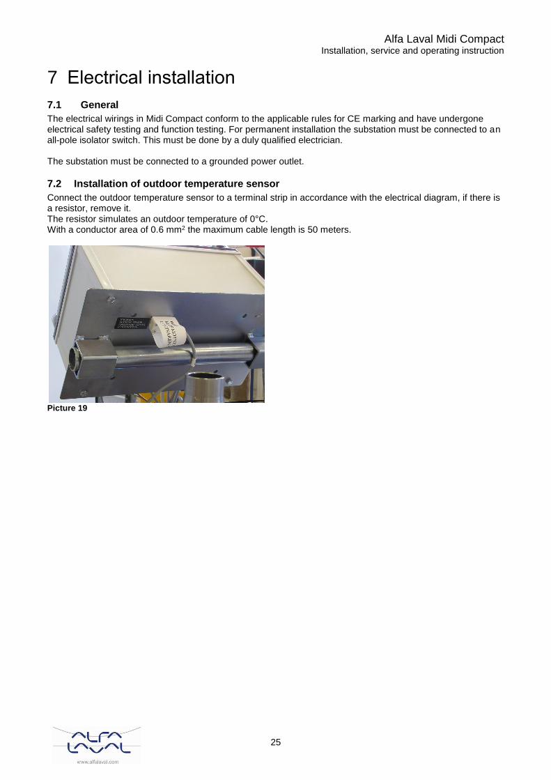
7.2 Installation of outdoor temperature sensor
Connect the outdoor temperature sensor to a terminal strip in accordance with the electrical diagram, if there is a resistor, remove it. The resistor simulates an outdoor temperature of 0°C. With a conductor area of 0.6 mm2 the maximum cable length is 50 meters.
Picture 19

Alfa Laval Midi Compact Installation, service and operating instruction
26
7.3 Electrical circuit diagram EU
Picture 20

Alfa Laval Midi Compact Installation, service and operating instruction
27
8 Schematic diagram, main components
8.1 Midi Compact
Picture 21
Alfa Laval Midi Compact Installation, service and operating instruction
28
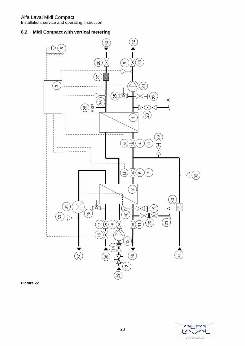
8.2 Midi Compact with vertical metering
Picture 22

Alfa Laval Midi Compact Installation, service and operating instruction
29
8.3 Midi Compact with horizontal metering
Picture 23

Alfa Laval Midi Compact Installation, service and operating instruction
30
9 Pump settings and pump capacity
9.1 General
Mini Compact is equipped with two circulation pumps, one for the hot water circulation, DHWC-pump, and one for the heating circuit. The DHWC pump is a traditional three speed circulation pump. The DHWC pump has a switch where the speed/capacity can be set. The circulation pump for heating circuit is a pressure controlled pump. The pressure controlled pump has an operator control panel where the different settings can be done. If all heaters are not at the same temperature, reset the pump to a higher setting. If there is a whistling sound in the pipe system, select a lower output setting. The lowest possible setting is the most economical For more information, please see below.
9.2 DHWC pump Grundfos UPSO 15-55, capacity
Picture 24
Picture 25

Alfa Laval Midi Compact Installation, service and operating instruction
31
9.3 Heating circuit Grundfos Magna 25-100, settings and capacity
The pump is factory pre-set on AUTOADAPT without automatic night time decrease.
Pos. Description
1 Buttons for setting
2 Indicator lights for operating and fault indication and symbol for indication of external control
3 Button for change of control mode
4 Light symbols for indication of control mode and night-time duty
5 Light fields for indication of head, flow and operating mode
Picture 26
9.3.1 Control modes
The Magna pump can be set to the one of three possible control modes.
• AUTOADAPT (factory setting)
• Proportional pressure
• Constant pressure.
Each of the control modes can be combined with automatic night-time duty. AUTOADAPT (factory setting) This mode is recommended for most heating installations. During operation, the pump automatically makes the necessary adjustment to the actual system characteristic. This setting ensures minimum energy consumption and noise level which reduces operating costs and increases comfort. Proportional-pressure control The pump head is changed continuously in accordance with the water demand in the system. The desired set point can be set on the pump control panel. Constant-pressure control A constant head is maintained, irrespective of water demand. The desired set point can be set on the pump control panel. Automatic night-time duty The pump changes automatically between normal duty and night-time duty depending on the flow-pipe temperature. Automatic night-time duty can be combined with the above-mentioned control modes.
Alfa Laval Midi Compact Installation, service and operating instruction
32
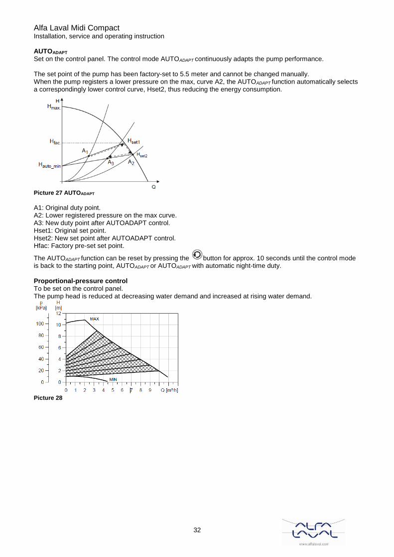
AUTOADAPT Set on the control panel. The control mode AUTOADAPT continuously adapts the pump performance. The set point of the pump has been factory-set to 5.5 meter and cannot be changed manually. When the pump registers a lower pressure on the max, curve A2, the AUTOADAPT function automatically selects a correspondingly lower control curve, Hset2, thus reducing the energy consumption.
Picture 27 AUTOADAPT
A1: Original duty point. A2: Lower registered pressure on the max curve. A3: New duty point after AUTOADAPT control. Hset1: Original set point. Hset2: New set point after AUTOADAPT control. Hfac: Factory pre-set set point.
The AUTOADAPT function can be reset by pressing the button for approx. 10 seconds until the control mode is back to the starting point, AUTOADAPT or AUTOADAPT with automatic night-time duty. Proportional-pressure control To be set on the control panel. The pump head is reduced at decreasing water demand and increased at rising water demand.
Picture 28
Alfa Laval Midi Compact Installation, service and operating instruction
33
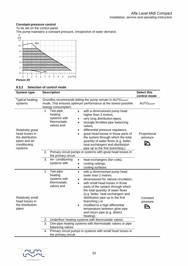
Constant-pressure control To be set on the control panel.
The pump maintains a constant pressure, irrespective of water demand.
Picture 29
9.3.2 Selection of control mode
System type Description Select this control mode
Typical heating systems
Grundfos recommends letting the pump remain in AUTOADAPT mode. This ensures optimum performance at the lowest possible energy consumption.
AUTOADAPT
Relatively great head losses in the distribution pipes and air-conditioning systems
1. Two-pipe heating systems with thermostatic valves and:
• with a dimensioned pump head higher than 3 metres,
• very long distribution pipes,
• strongly throttled pipe balancing valves,
• differential pressure regulators,
• great head losses in those parts of the system through which the total quantity of water flows (e.g. boiler, heat exchangers and distribution pipe up to the first branching.)
Proportional pressure
2. Primary circuit pumps in systems with great head losses in the primary circuit.
3. Air- conditioning systems with
• heat exchangers (fan coils),
• cooling ceilings,
• cooling surfaces
Relatively small head losses in the distribution pipes
1. Two-pipe heating systems with thermostatic valves and
• with a dimensioned pump head lower than 2 metres,
• dimensioned for natural circulation,
• with small head losses in those parts of the system through which the total quantity of water flows (e.g. boiler, heat exchangers and distribution pipe up to the first branching.) or
• modified to a high differential temperature between glow pipe and return pipe (e.g. district heating).
Constant pressure
2. Underfloor heating systems with thermostatic valves.
3. One-pipe heating systems with thermostatic valves or pipe balancing valves
4. Primary circuit pumps in systems with small head losses in the primary circuit.
Alfa Laval Midi Compact Installation, service and operating instruction
34
Set point setting If AUTOADAPT is selected, the set point cannot be set.
The set point can be set by pressing or when the pump is in control mode: • Proportional pressure • Constant pressure • Constant-curve duty Set the set point so that it matches the system. A too high setting may result in noise in the system whereas a too low setting may result in insufficient heating or cooling in the system. Automatic night-time decrease To be set on the control panel. Once automatic night-time duty has been activated, the pump automatically changes between normal duty and night-time duty (duty at low performance). Changeover between normal duty and night-time duty is dependent on the flow-pipe temperature. The pump automatically changes over to night-time duty when the built-in sensor registers a flow-pipe temperature drop of more than 10-15 °C within approx. 2 hours. The temperature drop must be at least 0.1 °C/min. Changeover to normal duty takes place without a time lag when the temperature has increased by approx. 10 °C.
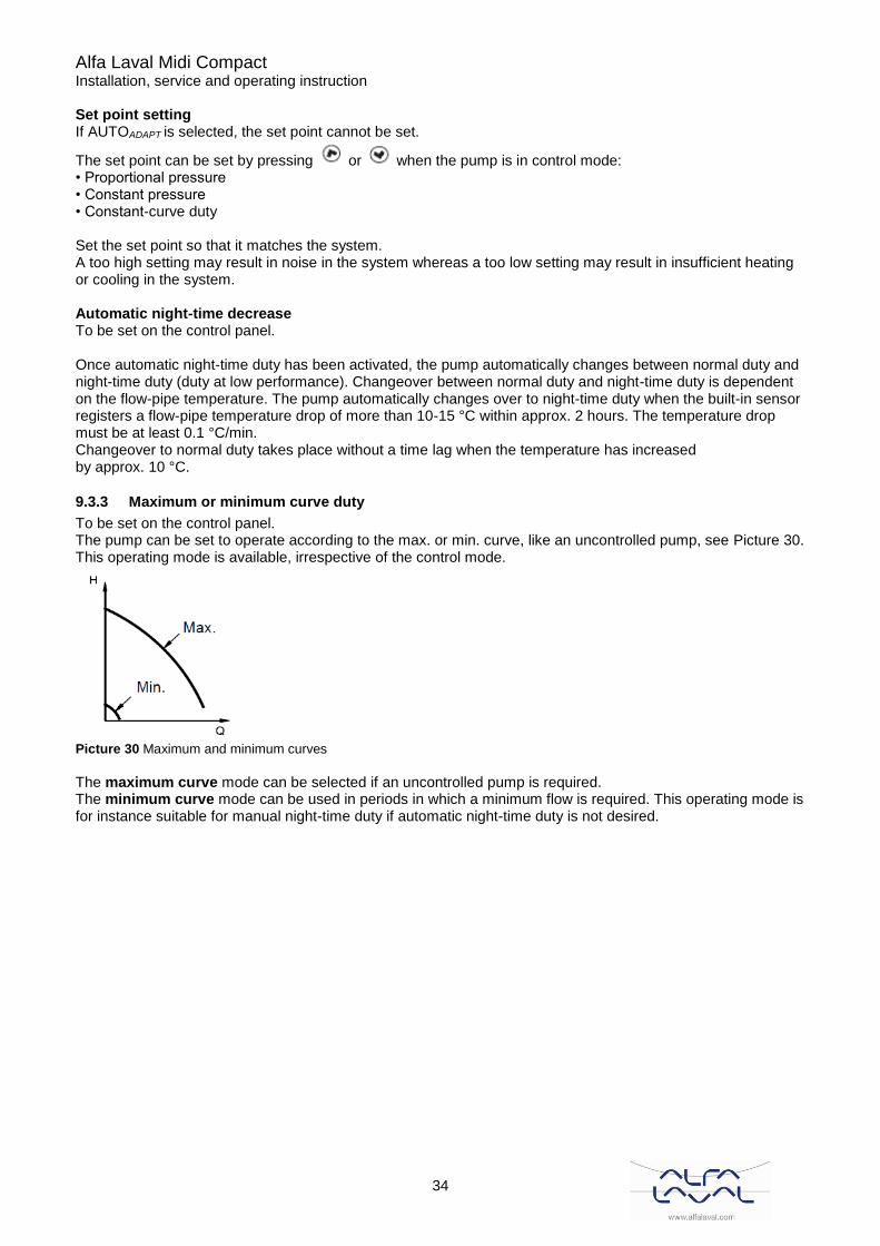
9.3.3 Maximum or minimum curve duty
To be set on the control panel. The pump can be set to operate according to the max. or min. curve, like an uncontrolled pump, see Picture 30. This operating mode is available, irrespective of the control mode.
Picture 30 Maximum and minimum curves
The maximum curve mode can be selected if an uncontrolled pump is required. The minimum curve mode can be used in periods in which a minimum flow is required. This operating mode is for instance suitable for manual night-time duty if automatic night-time duty is not desired.

Alfa Laval Midi Compact Installation, service and operating instruction
35
9.3.4 Control mode setting
To change the control mode, press , pos. 3 on the control panel, according to this cycle:
Picture 31
Automatic night-time duty can be activated together with each of the control modes. The light symbols, pos. 4 on the control panel, indicate the pump settings:
Light in Control mode Automatic night-time
duty
AutoADAPT AutoADAPT NO
Proportional pressure
NO
Constant pressure NO
- Constant curve NO
AutoADAPT
AutoADAPT YES
Proportional pressure
YES
Constant pressure YES
-
Constant curve YES
“-“ = no light

Alfa Laval Midi Compact Installation, service and operating instruction
36
9.3.5 Set point setting
Set the set point of the pump by pressing or when the pump has been set to proportional-pressure control, constant-pressure control or constant-curve duty. The light fields, pos. 5 on the control panel, indicate the set point set. The light fields can indicate a maximum set point of 9 meter.
Picture 32
9.3.6 Setting to maximum curve duty
To change over to the maximum curve, press continuously until "MAX" illuminates. To change back, press
continuously until the desired set point is indicated.
Picture 33 Maximum curve

Alfa Laval Midi Compact Installation, service and operating instruction
37
9.3.7 Setting to minimum curve duty
To change over to the min. curve, press continuously until "MIN" illuminates. To change back, press continuously until the desired set point is indicated.
Picture 34 Minimum curve
9.3.8 Starting and stopping pump
To stop the pump, press continuously until "STOP" illuminates. When the pump is stopped, the green indicator light will be flashing.
To start the pump, press continuously.
9.3.9 Resetting of fault indications
The fault indications are reset by briefly pressing any button. The settings remain unchanged. If the fault has not disappeared, the fault indication will reappear. The time until the fault reappears may vary from 0 to 255 seconds.
Alfa Laval Midi Compact Installation, service and operating instruction
38
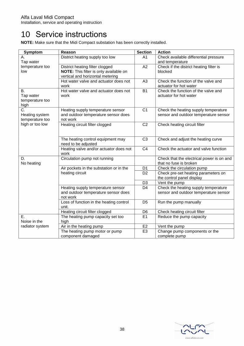
10 Service instructions NOTE: Make sure that the Midi Compact substation has been correctly installed.
Symptom Reason Section Action
A. Tap water temperature too low
District heating supply too low A1 Check available differential pressure and temperature
District heating filter clogged NOTE: This filter is only available on vertical and horizontal metering
A2 Check if the district heating filter is blocked
Hot water valve and actuator does not work
A3 Check the function of the valve and actuator for hot water
B. Tap water temperature too high
Hot water valve and actuator does not work
B1 Check the function of the valve and actuator for hot water
C. Heating system temperature too high or too low
Heating supply temperature sensor and outdoor temperature sensor does not work
C1 Check the heating supply temperature sensor and outdoor temperature sensor
Heating circuit filter clogged C2 Check heating circuit filter
The heating control equipment may need to be adjusted
C3 Check and adjust the heating curve
Heating valve and/or actuator does not work
C4 Check the actuator and valve function
D. No heating
Circulation pump not running Check that the electrical power is on and that no fuse is broken
Air pockets in the substation or in the heating circuit
D1 Check the circulation pump
D2 Check pre-set heating parameters on the control panel display
D3 Vent the pump
Heating supply temperature sensor and outdoor temperature sensor does not work
D4 Check the heating supply temperature sensor and outdoor temperature sensor
Loss of function in the heating control unit.
D5 Run the pump manually
Heating circuit filter clogged D6 Check heating circuit filter
E. Noise in the radiator system
The heating pump capacity set too high
E1 Reduce the pump capacity
Air in the heating pump E2 Vent the pump
The heating pump motor or pump component damaged
E3 Change pump components or the complete pump
Alfa Laval Midi Compact Installation, service and operating instruction
39
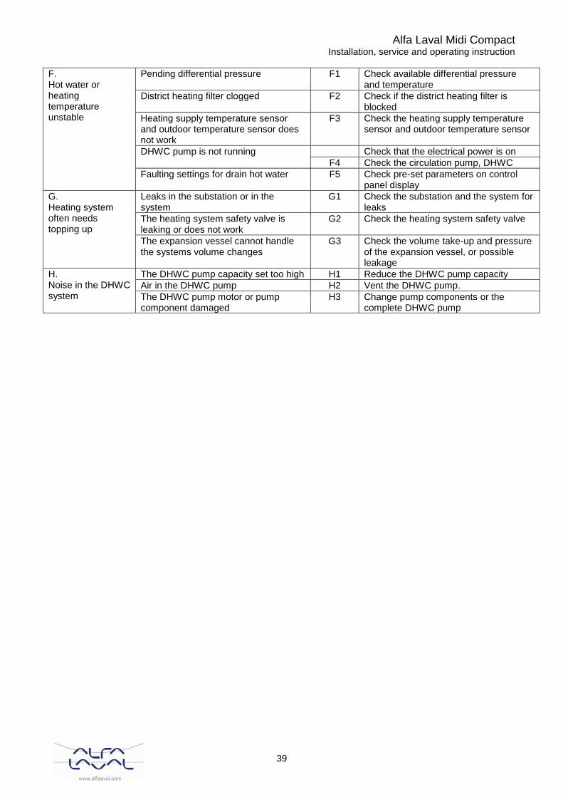
F. Hot water or heating temperature unstable
Pending differential pressure F1 Check available differential pressure and temperature
District heating filter clogged F2 Check if the district heating filter is blocked
Heating supply temperature sensor and outdoor temperature sensor does not work
F3 Check the heating supply temperature sensor and outdoor temperature sensor
DHWC pump is not running Check that the electrical power is on
F4 Check the circulation pump, DHWC
Faulting settings for drain hot water F5 Check pre-set parameters on control panel display
G. Heating system often needs topping up
Leaks in the substation or in the system
G1 Check the substation and the system for leaks
The heating system safety valve is leaking or does not work
G2 Check the heating system safety valve
The expansion vessel cannot handle the systems volume changes
G3 Check the volume take-up and pressure of the expansion vessel, or possible leakage
H. Noise in the DHWC system
The DHWC pump capacity set too high H1 Reduce the DHWC pump capacity
Air in the DHWC pump H2 Vent the DHWC pump.
The DHWC pump motor or pump component damaged
H3 Change pump components or the complete DHWC pump

Alfa Laval Midi Compact Installation, service and operating instruction
40
A. Tap water temperature too low
A.1 Check available differential pressure and temperature The temperature can be checked by means of the energy meter, minimum 65ºC, or at the district heating medium supply. The hot water drain temperature can be monitored on the control panel display, parameter P11.
A.2 Check if the district heating filter is blocked. Note: This filter is only available on vertical and horizontal metering. Close the shutoff valves for primary supply and primary return. Release the filter holder and remove the cartridge (Picture 35). Clean the filter with water and refit the cartridge. Screw the filter holder with a momentum of 10-20 Nm. Open the primary supply and return valves carefully. After finishing repair; open the shutoff valves. Start with primary supply and then the return lines, in order to avoid pollutions in the system. Open up the valves slowly to avoid pressure surges.
A.3 Check the function for the hot water valve and actuator Test the actuator by viewing parameter P88 on the control panel display. To open the actuator press (-) button for 30 seconds. Control that the actuator opens, i.e. that the threaded rod closes in on the red marker and the displayed value turns to 0 V. To shut the actuator press the (+) button for approximately 30 seconds. Check that that the threaded rod closes in on the blue marker and the displayed value turns to 10 V. When the actuator closes, it pulls the valve guide pin towards itself. Before the hot water valve can be checked the actuator must be dismantled. Unscrew the screws on the shackle holding the actuator to the valve (Picture 36). Dismantle the actuator from the valve (Picture 37).
Picture 36
Picture 37
Picture 35

Alfa Laval Midi Compact Installation, service and operating instruction
41
Press the valve guide pin gently (Picture 38) and check the valve´s travel and spring back. Note: The valve may be very hot!
Picture 38
B. Tap water temperature too high
B.1 Check the function for the hot water valve and actuator
See A.3.
C. Heating system temperature too high or too low
C.1 Check the heating supply temperature sensor and outdoor temperature sensor Check the heating supply temperature sensor and the outdoor temperature sensor for correct placement and function. This is controlled via the control panel display parameters P 03 and P01, see 5.1 Read of temperatures.
C.2 Check heating circuit filter Disconnect the electrical power supply. Shut closing valves for the heating supply and return. Drain the system with the draining valve. Release the filter holder and remove the cartridge (Picture 39). Clean the filter in water and refit the cartridge. Screw the filter holder with a momentum of 10-20 Nm. Carefully open up the shutoff valves for the heating supply and return.
C.3 Check and adjust the heating curve
See chapter 5.4 Adjust the controller curve and change the selected heating curve on parameter 05.
Picture 39
Alfa Laval Midi Compact Installation, service and operating instruction
42
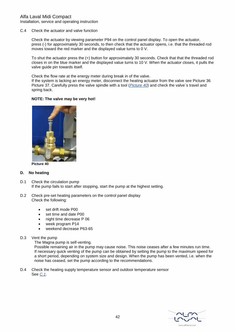
C.4 Check the actuator and valve function
Check the actuator by viewing parameter P94 on the control panel display. To open the actuator, press (-) for approximately 30 seconds, to then check that the actuator opens, i.e. that the threaded rod moves toward the red marker and the displayed value turns to 0 V. To shut the actuator press the (+) button for approximately 30 seconds. Check that that the threaded rod closes in on the blue marker and the displayed value turns to 10 V. When the actuator closes, it pulls the valve guide pin towards itself. Check the flow rate at the energy meter during break in of the valve. If the system is lacking an energy meter, disconnect the heating actuator from the valve see Picture 36 Picture 37. Carefully press the valve spindle with a tool (Picture 40) and check the valve´s travel and spring back. NOTE: The valve may be very hot!
Picture 40
D. No heating
D.1 Check the circulation pump
If the pump fails to start after stopping, start the pump at the highest setting.
D.2 Check pre-set heating parameters on the control panel display Check the following:
• set drift mode P00
• set time and date P00
• night time decrease P 06
• week program P14
• weekend decrease P63-65
D.3 Vent the pump The Magna pump is self-venting. Possible remaining air in the pump may cause noise. This noise ceases after a few minutes run time. If necessary quick venting of the pump can be obtained by setting the pump to the maximum speed for a short period, depending on system size and design. When the pump has been vented, i.e. when the noise has ceased, set the pump according to the recommendations.
D.4 Check the heating supply temperature sensor and outdoor temperature sensor
See C.1.

Alfa Laval Midi Compact Installation, service and operating instruction
43
D.5 Run the pump manually If it becomes necessary to run the pump and actuator manually, this can be done by disconnecting the power to the operator control panel. Disconnect the electrical plug for the pump. Connect the replacement cable to the power supply and to the circulation pump. Next, open the heating valve manually using the red knob on the actuator, see Picture 41. Flick down the red knob and open the valve enough to supply the house property´s heating demand. This is to be regarded as a temporary solution until the control unit problem is solved.
D.6 Check heating circuit filter
See C.2.
E. Noise in the radiator system This instruction is suitable for both the DHWC and the radiator pump
E.1 Reduce the pump capacity Reduce the pump capacity by selecting a lower setting on the pump when needed. Low pump capacity is the more economical option.
E.2 Vent the pump E.2.1 Magna pump
The pump is self-venting. See D.3.
E.2.2 Grundfos UPS pump Set the pump to speed III. Loosen the pump motor end nut to and let it stay opened until the air in the pump is released. When the pump has been vented, i.e. when the noise has ceased, set the pump according to the recommendations.
E.3 Change the pump components or the complete pump If it is necessary to change the driving side of the pump, it can be dismantled without removing the entire pump. See chapter 11 Maintenance and repairs.
F. Unstable hot water and/or heating temperature
F.1 Check available differential pressure and temperature for district heat inlet from supplier
See A.1. F.2 Check if district heat filter on primary inlet is clogged
Clean if needed. See A.2. F.3 Check flow rate sensor and outdoor temperature sensor
See C.1.
Picture 41
Alfa Laval Midi Compact Installation, service and operating instruction
44
F.4 Check DHWC pump.
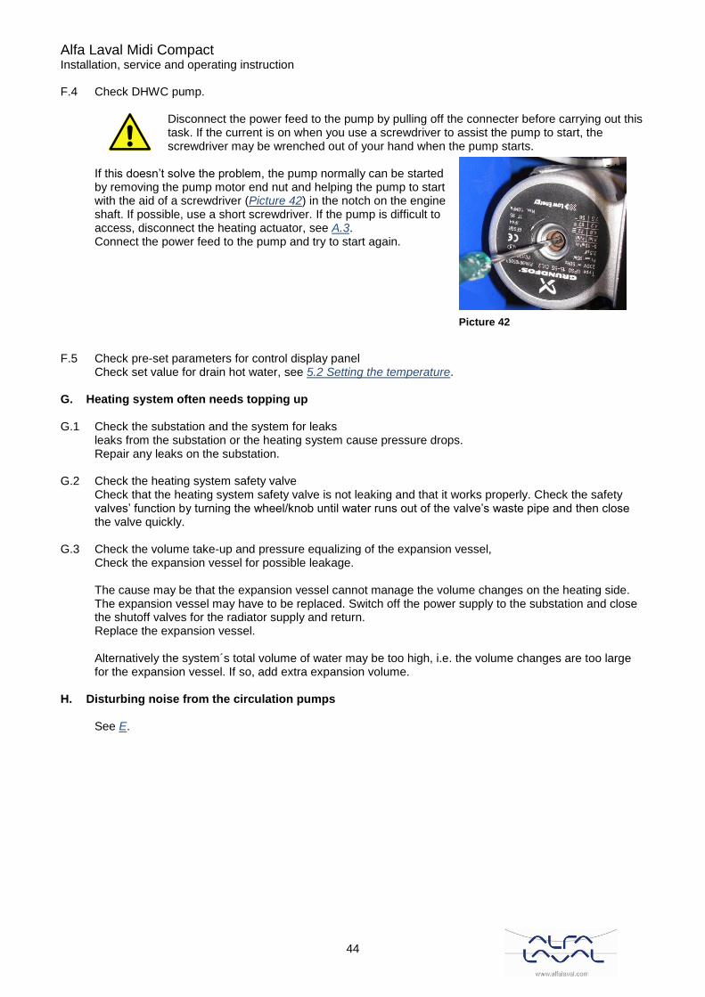
Disconnect the power feed to the pump by pulling off the connecter before carrying out this task. If the current is on when you use a screwdriver to assist the pump to start, the screwdriver may be wrenched out of your hand when the pump starts.
If this doesn’t solve the problem, the pump normally can be started by removing the pump motor end nut and helping the pump to start with the aid of a screwdriver (Picture 42) in the notch on the engine shaft. If possible, use a short screwdriver. If the pump is difficult to access, disconnect the heating actuator, see A.3. Connect the power feed to the pump and try to start again.
F.5 Check pre-set parameters for control display panel
Check set value for drain hot water, see 5.2 Setting the temperature.
G. Heating system often needs topping up
G.1 Check the substation and the system for leaks leaks from the substation or the heating system cause pressure drops. Repair any leaks on the substation.
G.2 Check the heating system safety valve Check that the heating system safety valve is not leaking and that it works properly. Check the safety valves’ function by turning the wheel/knob until water runs out of the valve’s waste pipe and then close the valve quickly.
G.3 Check the volume take-up and pressure equalizing of the expansion vessel, Check the expansion vessel for possible leakage. The cause may be that the expansion vessel cannot manage the volume changes on the heating side. The expansion vessel may have to be replaced. Switch off the power supply to the substation and close the shutoff valves for the radiator supply and return. Replace the expansion vessel. Alternatively the system´s total volume of water may be too high, i.e. the volume changes are too large for the expansion vessel. If so, add extra expansion volume.
H. Disturbing noise from the circulation pumps
See E.
Picture 42
Alfa Laval Midi Compact Installation, service and operating instruction
45
11 Maintenance and repairs When carrying out repairs, please contact your local service partner.
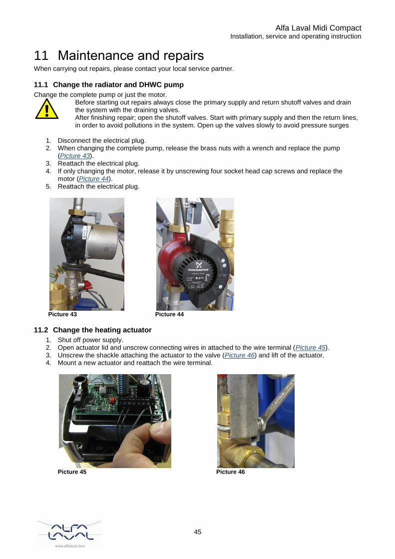
11.1 Change the radiator and DHWC pump
Change the complete pump or just the motor.
Before starting out repairs always close the primary supply and return shutoff valves and drain the system with the draining valves. After finishing repair; open the shutoff valves. Start with primary supply and then the return lines, in order to avoid pollutions in the system. Open up the valves slowly to avoid pressure surges
1. Disconnect the electrical plug. 2. When changing the complete pump, release the brass nuts with a wrench and replace the pump
(Picture 43). 3. Reattach the electrical plug. 4. If only changing the motor, release it by unscrewing four socket head cap screws and replace the
motor (Picture 44). 5. Reattach the electrical plug.
Picture 43
Picture 44
11.2 Change the heating actuator
1. Shut off power supply. 2. Open actuator lid and unscrew connecting wires in attached to the wire terminal (Picture 45). 3. Unscrew the shackle attaching the actuator to the valve (Picture 46) and lift of the actuator. 4. Mount a new actuator and reattach the wire terminal.
Picture 45
Picture 46
Alfa Laval Midi Compact Installation, service and operating instruction
46
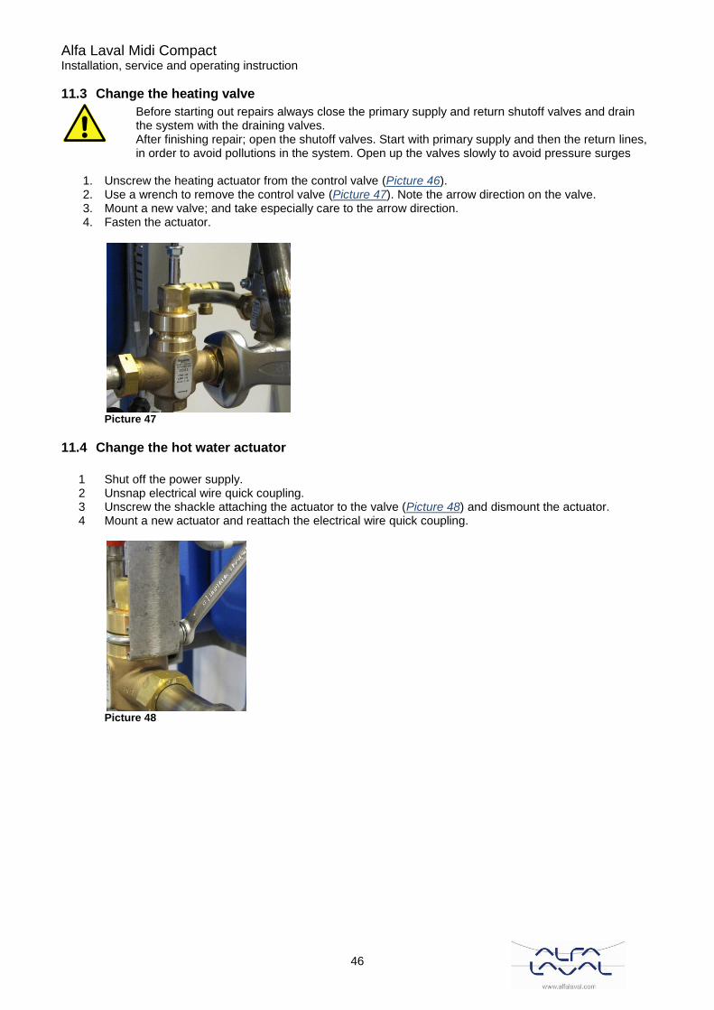
11.3 Change the heating valve
Before starting out repairs always close the primary supply and return shutoff valves and drain the system with the draining valves. After finishing repair; open the shutoff valves. Start with primary supply and then the return lines, in order to avoid pollutions in the system. Open up the valves slowly to avoid pressure surges
1. Unscrew the heating actuator from the control valve (Picture 46). 2. Use a wrench to remove the control valve (Picture 47). Note the arrow direction on the valve. 3. Mount a new valve; and take especially care to the arrow direction. 4. Fasten the actuator.
Picture 47
11.4 Change the hot water actuator
1 Shut off the power supply. 2 Unsnap electrical wire quick coupling. 3 Unscrew the shackle attaching the actuator to the valve (Picture 48) and dismount the actuator. 4 Mount a new actuator and reattach the electrical wire quick coupling.
Picture 48
Alfa Laval Midi Compact Installation, service and operating instruction
47
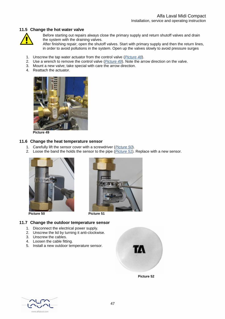
11.5 Change the hot water valve
Before starting out repairs always close the primary supply and return shutoff valves and drain the system with the draining valves. After finishing repair; open the shutoff valves. Start with primary supply and then the return lines, in order to avoid pollutions in the system. Open up the valves slowly to avoid pressure surges
1. Unscrew the tap water actuator from the control valve (Picture 48). 2. Use a wrench to remove the control valve (Picture 49). Note the arrow direction on the valve. 3. Mount a new valve; take special with care the arrow direction. 4. Reattach the actuator.
Picture 49
11.6 Change the heat temperature sensor
1. Carefully lift the sensor cover with a screwdriver (Picture 50). 2. Loose the band the holds the sensor to the pipe (Picture 51). Replace with a new sensor.
Picture 50
Picture 51
11.7 Change the outdoor temperature sensor
1. Disconnect the electrical power supply. 2. Unscrew the lid by turning it anti-clockwise. 3. Unscrew the cables. 4. Loosen the cable fitting. 5. Install a new outdoor temperature sensor.
Picture 52
Alfa Laval Midi Compact Installation, service and operating instruction
48
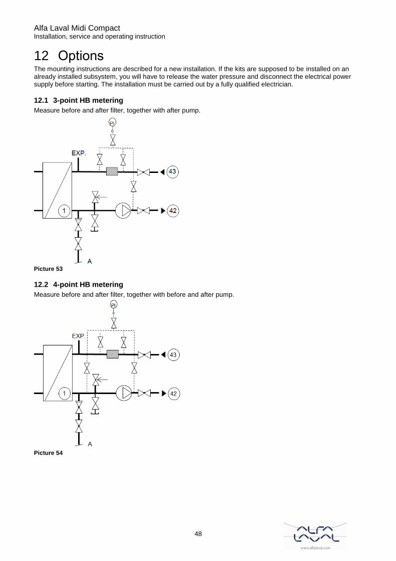
12 Options The mounting instructions are described for a new installation. If the kits are supposed to be installed on an already installed subsystem, you will have to release the water pressure and disconnect the electrical power supply before starting. The installation must be carried out by a fully qualified electrician.
12.1 3-point HB metering
Measure before and after filter, together with after pump.
Picture 53
12.2 4-point HB metering
Measure before and after filter, together with before and after pump.
Picture 54

Alfa Laval Midi Compact Installation, service and operating instruction
49
12.3 GENI module
Function:
• external analog control of head or speed via a signal from an external 0-10 V signal transmitter.
• external forced control via inputs for: - max. curve - min. curve
• bus communication via GENIbus The pump can be controlled and monitored by a Grundfos Control MPC Series 2000, a building management system or another type of external control system.
• external start/stop The pump can be started and stopped via the = digital input.
Alfa Laval Midi Compact Installation, service and operating instruction
50
13 Operation data and capacity
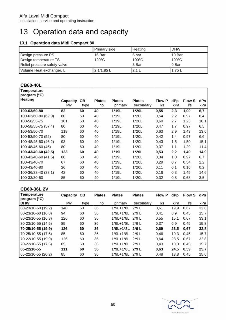
13.1 Operation data Midi Compact 80
Primary side Heating DHW
Design pressure PS 16 Bar 6 bar 10 Bar
Design temperature TS 120°C 100°C 100°C
Relief pressure safety-valve - 3 Bar 9 Bar
Volume Heat exchanger, L 2,1/1,85 L 2,1 L 1,75 L
CB60-40L Temperature program (°C) Heating Capacity CB Plates Plates Plates Flow P dPp Flow S dPs
kW type no primary secondary l/s kPa l/s kPa
100-63/60-80 82 60 40 1*19L 1*20L 0,55 2,3 1,00 6,7
100-63/60-80 (62,9) 80 60 40 1*19L 1*20L 0,54 2,2 0,97 6,4
100-58/55-75 101 60 40 1*19L 1*20L 0,60 2,7 1,23 10,1
100-58/55-75 (57,4) 80 60 40 1*19L 1*20L 0,47 1,7 0,97 6,5
100-53/50-70 118 60 40 1*19L 1*20L 0,63 2,9 1,43 13,6
100-53/50-70 (52) 80 60 40 1*19L 1*20L 0,42 1,4 0,97 6,6
100-48/45-60 (46,2) 93 60 40 1*19L 1*20L 0,43 1,5 1,50 15,1
100-48/45-60 (46) 80 60 40 1*19L 1*20L 0,37 1,1 1,29 11,4
100-43/40-60 (42,5) 123 60 40 1*19L 1*20L 0,53 2,2 1,49 14,9
100-43/40-60 (41,5) 80 60 40 1*19L 1*20L 0,34 1,0 0,97 6,7
100-43/40-70 67 60 40 1*19L 1*20L 0,29 0,7 0,54 2,2
100-43/40-80 26 60 40 1*19L 1*20L 0,11 0,1 0,16 0,2
100-36/33-40 (33,1) 42 60 40 1*19L 1*20L 0,16 0,3 1,45 14,6
100-33/30-60 85 60 40 1*19L 1*20L 0,32 0,8 0,68 3,5
CB60-36L 2V
Temperature program (°C) DHW
Capacity CB Plates Plates Plates Flow P dPp Flow S dPs
kW type no primary secondary l/s kPa l/s kPa
80-23/10-60 (19,2) 140 60 36 1*9L+1*8L 2*9 L 0,61 19,9 0,67 32,8
80-23/10-60 (16,8) 94 60 36 1*9L+1*8L 2*9 L 0,41 8,9 0,45 15,7
80-23/10-55 (16,3) 126 60 36 1*9L+1*8L 2*9 L 0,55 15,1 0,67 33,1
80-23/10-55 (14,5) 85 60 36 1*9L+1*8L 2*9 L 0,37 6,9 0,45 15,8
70-25/10-55 (19,9) 126 60 36 1*9L+1*8L 2*9 L 0,69 23,5 0,67 32,8
70-25/10-55 (17,5) 85 60 36 1*9L+1*8L 2*9 L 0,46 10,3 0,45 15,7
70-22/10-55 (19,9) 126 60 36 1*9L+1*8L 2*9 L 0,64 23,5 0,67 32,8
70-22/10-55 (17,5) 85 60 36 1*9L+1*8L 2*9 L 0,43 10,3 0,45 15,7
65-22/10-55 111 60 36 1*9L+1*8L 2*9 L 0,63 24,5 0,59 25,7
65-22/10-55 (20,2) 85 60 36 1*9L+1*8L 2*9 L 0,48 13,8 0,45 15,6
Alfa Laval Midi Compact Installation, service and operating instruction
51
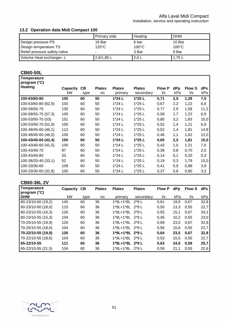
13.2 Operation data Midi Compact 100
Primary side Heating DHW
Design pressure PS 16 Bar 6 bar 10 Bar
Design temperature TS 120°C 100°C 100°C
Relief pressure safety-valve - 3 Bar 9 Bar
Volume Heat exchanger, L 2,6/1,85 L 2,6 L 1,75 L
CB60-50L Temperature program (°C) Heating Capacity CB Plates Plates Plates Flow P dPp Flow S dPs
kW type no primary secondary l/s kPa l/s kPa
100-63/60-80 105 60 50 1*24 L 1*25 L 0,71 2,5 1,28 7,5
100-63/60-80 (62,9) 100 60 50 1*24 L 1*25 L 0,67 2,2 1,22 6,8
100-58/55-75 130 60 50 1*24 L 1*25 L 0,77 2,9 1,58 11,2
100-58/55-75 (57,3) 100 60 50 1*24 L 1*25 L 0,58 1,7 1,22 6,9
100-53/50-70 (53) 151 60 50 1*24 L 1*25 L 0,80 3,2 1,83 15,0
100-53/50-70 (51,9) 100 60 50 1*24 L 1*25 L 0,52 1,4 1,21 6,9
100-48/45-60 (46,1) 112 60 50 1*24 L 1*25 L 0,52 1,4 1,81 14,8
100-48/45-60 (46,0) 100 60 50 1*24 L 1*25 L 0,46 1,1 1,62 12,0
100-43/40-60 (42,4) 150 60 50 1*24 L 1*25 L 0,65 2,2 1,81 15,0
100-43/40-60 (41,5) 100 60 50 1*24 L 1*25 L 0,43 1,0 1,21 7,0
100-43/40-70 87 60 50 1*24 L 1*25 L 0,38 0,8 0,70 2,5
100-43/40-80 33 60 50 1*24 L 1*25 L 0,14 0,1 0,20 0,3
100-36/33-40 (33,1) 52 60 50 1*24 L 1*25 L 0,19 0,3 1,79 15,0
100-33/30-60 109 60 50 1*24 L 1*25 L 0,41 0,9 0,88 3,9
100-33/30-60 (32,8) 100 60 50 1*24 L 1*25 L 0,37 0,8 0,80 3,3
CB60-36L 2V
Temperature program (°C) DHW
Capacity CB Plates Plates Plates Flow P dPp Flow S dPs
kW type no primary secondary l/s kPa l/s kPa
80-23/10-60 (19,2) 140 60 36 1*9L+1*8L 2*9 L 0,61 19,9 0,67 32,8
80-23/10-60 (18,0) 115 60 36 1*9L+1*8L 2*9 L 0,50 13,3 0,55 22,7
80-23/10-55 (16,3) 126 60 36 1*9L+1*8L 2*9 L 0,55 15,1 0,67 33,1
80-23/10-55 (15,3) 104 60 36 1*9L+1*8L 2*9 L 0,45 10,2 0,55 23,0
70-25/10-55 (19,9) 126 60 36 1*9L+1*8L 2*9 L 0,69 23,5 0,67 32,8
70-25/10-55 (18,6) 104 60 36 1*9L+1*8L 2*9 L 0,56 15,6 0,55 22,7
70-22/10-55 (19,9) 126 60 36 1*9L+1*8L 2*9 L 0,64 23,5 0,67 32,8
70-22/10-55 (18,6) 104 60 36 1*9L+1*8L 2*9 L 0,53 15,5 0,55 22,7
65-22/10-55 111 60 36 1*9L+1*8L 2*9 L 0,63 24,5 0,59 25,7
65-22/10-55 (21,5) 104 60 36 1*9L+1*8L 2*9 L 0,59 21,1 0,55 22,6

Alfa Laval Midi Compact Installation, service and operating instruction
52
13.3 Operation data Midi Compact 160
Primary side Heating DHW
Design pressure PS 16 Bar 16 bar 10 Bar
Design temperature TS 120°C 100°C 100°C
Relief pressure safety-valve - 3 Bar 9 Bar
Volume Heat exchanger, L 4,1/2,27 L 4,1 L 2,16 L
CB60-80L Temperature program (°C) Heating Capacity CB Plates Plates Plates Flow P dPp Flow S dPs
kW type no primary secondary l/s kPa l/s kPa
100-63/60-80 162 60 80 1*39L 1*40L 1,09 2,7 1,97 8,7
100-63/60-80 (62,8) 160 60 80 1*39L 1*40L 1,07 2,7 1,95 8,5
100-58/55-75 162 60 80 1*39L 1*40L 0,96 2,2 1,97 8,8
100-58/55-75 (57,2) 160 60 80 1*39L 1*40L 0,93 2,1 1,95 14,9
100-53/50-70 (51,9) 164 60 80 1*39L 1*40L 0,86 1,8 1,98 8,9
100-53/50-70 (51,9) 160 60 80 1*39L 1*40L 0,83 1,7 1,94 8,6
100-48/45-60 (45,6) 122 60 80 1*39L 1*40L 0,58 0,9 1,97 8,9
100-43/40-60 (41,4) 163 60 80 1*39L 1*40L 0,71 1,2 1,97 9,0
100-43/40-60 (41,4) 160 60 80 1*39L 1*40L 0,68 1,1 1,93 8,7
100-43/40-70 144 60 80 1*39L 1*40L 0,63 1,0 1,16 3,3
100-43/40-80 56 60 80 1*39L 1*40L 0,24 0,2 0,34 0,3
100-36/33-40 (33,0) 57 60 80 1*39L 1*40L 0,22 0,2 1,96 9,1
100-33/30-60 181 60 80 1*39L 1*40L 0,67 1,1 1,45 5,1
CB60-44L 2V
Temperature program (°C) DHW
Capacity CB Plates Plates Plates Flow P dPp Flow S dPs
kW type no primary secondary l/s kPa l/s kPa
80-23/10-60 (19,1) 174 60 44 2*12L 1*12L+1*13L 0,75 20,5 0,83 33,2
80-23/10-60 (18,0) 146 60 44 2*12L 1*12L+1*13L 0,63 14,5 0,70 24,2
80-23/10-55 (16,1) 154 60 44 2*12L 1*12L+1*13L 0,67 15,2 0,82 32,8
80-23/10-55 (15,4) 132 60 44 2*12L 1*12L+1*13L 0,57 11,1 0,70 24,4
70-25/10-55 (19,8) 156 60 44 2*12L 1*12L+1*13L 0,85 24,2 0,83 33,2
70-25/10-55 (18,7) 132 60 44 2*12L 1*12L+1*13L 0,72 17,0 0,70 24,2
70-22/10-55 (19,8) 156 60 44 2*12L 1*12L+1*13L 0,80 24,2 0,83 33,2
70-22/10-55 (18,7) 132 60 44 2*12L 1*12L+1*13L 0,67 17,0 0,70 24,2
65-22/10-55 139 60 44 2*12L 1*12L+1*13L 0,79 26,0 0,74 26,6
65-22/10-55 (21,6) 132 60 44 2*12L 1*12L+1*13L 0,75 21,6 0,70 24,0
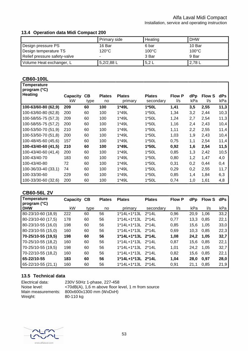
Alfa Laval Midi Compact Installation, service and operating instruction
53
13.4 Operation data Midi Compact 200
Primary side Heating DHW
Design pressure PS 16 Bar 6 bar 10 Bar
Design temperature TS 120°C 100°C 100°C
Relief pressure safety-valve - 3 Bar 9 Bar
Volume Heat exchanger, L 5,2/2,88 L 5,2 L 2,78 L
CB60-100L Temperature program (°C) Heating Capacity CB Plates Plates Plates Flow P dPp Flow S dPs
kW type no primary secondary l/s kPa l/s kPa
100-63/60-80 (62,9) 209 60 100 1*49L 1*50L 1,41 3,5 2,55 11,3
100-63/60-80 (62,8) 200 60 100 1*49L 1*50L 1,34 3,2 2,44 10,3
100-58/55-75 (57,3) 209 60 100 1*49L 1*50L 1,24 2,7 2,54 11,3
100-58/55-75 (57,2) 200 60 100 1*49L 1*50L 1,16 2,4 2,43 10,4
100-53/50-70 (51,9) 210 60 100 1*49L 1*50L 1,11 2,2 2,55 11,4
100-53/50-70 (51,8) 200 60 100 1*49L 1*50L 1,03 1,9 2,43 10,4
100-48/45-60 (45,6) 157 60 100 1*49L 1*50L 0,75 1,1 2,54 11,4
100-43/40-60 (41,5) 210 60 100 1*49L 1*50L 0,92 1,6 2,54 11,5
100-43/40-60 (41,4) 200 60 100 1*49L 1*50L 0,85 1,3 2,42 10,5
100-43/40-70 183 60 100 1*49L 1*50L 0,80 1,2 1,47 4,0
100-43/40-80 72 60 100 1*49L 1*50L 0,31 0,2 0,44 0,4
100-36/33-40 (33,1) 74 60 100 1*49L 1*50L 0,29 0,2 2,55 11,7
100-33/30-60 229 60 100 1*49L 1*50L 0,85 1,4 1,84 6,3
100-33/30-60 (32,6) 200 60 100 1*49L 1*50L 0,74 1,0 1,61 4,8
CB60-56L 2V
Temperature program (°C) DHW
Capacity CB Plates Plates Plates Flow P dPp Flow S dPs
kW type no primary secondary l/s kPa l/s kPa
80-23/10-60 (18,9) 222 60 56 1*14L+1*13L 2*14L 0,96 20,9 1,06 33,2
80-23/10-60 (17,5) 178 60 56 1*14L+1*13L 2*14L 0,77 13,3 0,85 22,1
80-23/10-55 (16,0) 198 60 56 1*14L+1*13L 2*14L 0,85 15,6 1,05 33,0
80-23/10-55 (15,0) 160 60 56 1*14L+1*13L 2*14L 0,69 10,3 0,85 22,3
70-25/10-55 (19,5) 198 60 56 1*14L+1*13L 2*14L 1,08 24,2 1,05 32,7
70-25/10-55 (18,2) 160 60 56 1*14L+1*13L 2*14L 0,87 15,6 0,85 22,1
70-25/10-55 (19,5) 198 60 56 1*14L+1*13L 2*14L 1,01 24,2 1,05 32,7
70-22/10-55 (18,2) 160 60 56 1*14L+1*13L 2*14L 0,82 15,6 0,85 22,1
65-22/10-55 183 60 56 1*14L+1*13L 2*14L 1,04 28,0 0,97 28,0
65-22/10-55 (21,1) 160 60 56 1*14L+1*13L 2*14L 0,91 21,1 0,85 21,9
13.5 Technical data
Electrical data: 230V 50Hz 1-phase, 227-458 Noise level: <70dB(A), 1,6 m above floor level, 1 m from source Main measurements: 800x600x1300 mm (WxDxH) Weight: 80-110 kg
Alfa Laval Midi Compact Installation, service and operating instruction
54
14 Declaration of conformity art 4.3
Alfa Laval Midi Compact Installation, service and operating instruction
55
15 Declaration of conformity Cat 1