Embed Size (px)
Citation preview
Manitowoc Beverage Equipment2100 Future Drive Sellersburg, IN 47172-1868Tel: 812.246.7000, 800.367.4233 Fax: 812.246.9922www.manitowocbeverage.com
In accordance with our policy of continuous product development andimprovement, this information is subject to change at any time without notice.
January 03, 2007 REV1
Single, Dual and Triple Granita Machine
INSTALLATION & SERVICE GUIDEPart Number 020001173
FOREWORDManitowoc Beverage Equipment (MBE) developed this manual as a reference guide for the owner/operator, service agent, and installer of this equipment. Please read this manual before installationor operation of the machine. A qualified service technician should perform installation and start-up of this equipment, consult the Troubleshooting Guide within this manual for service assistance.
If you cannot correct the service problem, call your MBE Service Agent or Distributor. Always have your model andserial number available when you call.
Your Service Agent___________________________________________________________________
Service Agent Telephone Number ______________________________________________________
Your Local MBE Distributor ___________________________________________________________
Distributor Telephone Number _________________________________________________________
Model Number ______________________________________________________________________
Serial Number _______________________________________________________________________
Installation Date _____________________________________________________________________
UNPACKING AND INSPECTIONNote: The unit was thoroughly inspected before leaving the factory. Any damage or irregularities shouldbe noted at the time of delivery.
WARRANTY INFORMATIONConsult your local MBE Distributor for terms and conditions of your warranty. Your warranty specificallyexcludes all beverage valve brixing, general adjustments, cleaning, accessories and related servicing.
Your warranty card must be returned to Manitowoc Beverage Equipment to activate the warranty on thisequipment. If a warranty card is not returned, the warranty period can begin when the equipment leavesthe MBE factory.
No equipment may be returned to Manitowoc Beverage Equipment without a written Return MerchandiseAuthorization (RMA). Equipment returned without an RMA will be refused at MBE’s dock and returned tothe sender at the sender’s expense.
Please contact your local MBE distributor for return procedures.
TABLE OF CONTENTSFOREWORD ........................................................................................................ 2UNPACKING AND INSPECTION......................................................................... 2WARRANTY INFORMATION ............................................................................... 2SAFETY ............................................................................................................... 5
IMPORTANT SAFETY INSTRUCTIONS ........................................................................... 5
CARBON DIOXIDE WARNING ......................................................................................... 5
QUALIFIED SERVICE PERSONNEL ................................................................................ 5
SHIPPING, STORAGE, AND RELOCATION ..................................................................... 5
ADDITIONAL WARNINGS................................................................................................ 5
GROUNDING INSTRUCTIONS ........................................................................................ 6
GENERAL SAFETY RULES ............................................................................................. 7
STOP FUNCTIONS ........................................................................................................... 7
PLATES ............................................................................................................................ 7
GENERAL INFORMATION .................................................................................. 8MANUFACTURER ............................................................................................................ 8
AUTHORIZED PERSONS ................................................................................................ 8
LAYOUT OF THE MANUAL ............................................................................................. 8
PURPOSE AND CONTENTS ............................................................................................ 8
WHO MUST READ THE MANUAL ................................................................................... 8
HOW TO KEEP THE MANUAL ......................................................................................... 9
SYMBOLS USED ............................................................................................................. 9
INSTALLATION .................................................................................................. 10LIST OF ACCESSORIES PROVIDED ............................................................................. 10
POSITIONING................................................................................................................. 10
DISPOSAL OF PACKING MATERIALS .......................................................................... 10
ELECTRICAL CONNECTION ..........................................................................................11
OPERATION ...................................................................................................... 11CONTROL PANEL ...........................................................................................................11
USE OF THE MACHINE ................................................................................................. 12
MAIN COMPONENTS .................................................................................................... 12
TECHNICAL DATA ......................................................................................................... 12
PACKAGING .................................................................................................................. 13
TABLE OF CONTENTSCONVEYANCE AND HANDLING ................................................................................... 13
STORAGE ...................................................................................................................... 13
PREPARING THE PRODUCT ......................................................................................... 14
STARTING A GRANITORE ............................................................................................. 15
ADJUSTING GRANITA CONSISTENCY......................................................................... 16
INDICATIONS FOR CORRECT USE ............................................................................. 17
EMERGENCY SITUATIONS ........................................................................................... 17
ACCESSORY (OPTIONAL) (LOCKING SYSTEM).......................................................... 17
USER MAINTENANCE ...................................................................................... 17PREVENTATIVE MAINTENANCE .................................................................................. 17
EMPTYING THE BOWLS ............................................................................................... 19
DISASSEMBLING THE DISPENSING TAP .................................................................... 19
REMOVING THE BOWL ................................................................................................. 20
WASHING AND SANITIZING THE COMPONENTS ....................................................... 20
REASSEMBLING THE WASHED COMPONENTS ......................................................... 21
RINSING CYCLE ............................................................................................................ 22
CLEANING THE DRIP TRAY .......................................................................................... 22
LIGHTED LID MAINTENANCE ....................................................................................... 23
BULB REPLACEMENT .................................................................................................. 23
CLEANING THE CONDENSER ...................................................................................... 23
CLEANING THE GRANITORE 1/1FF CONDENSER ...................................................... 24
CLEANING GRANITORE 2/2 FF - 3/3 FF COND ............................................................ 24
SCRAPPING................................................................................................................... 25
TROUBLESHOOTING .................................................................................................... 25
EXPLODED VIEWS, PARTS & DIAGRAMS ..................................................... 26GRANITORE 1 - 1 FF WIRING........................................................................................ 26
GRANITORE 2 - 2FF WIRING ........................................................................................ 27
GRANITORE 3 - 3FF 230V WIRING ............................................................................... 28
GRANITORE 3 - 3FF 115V WIRING................................................................................ 29
GRANITORE 1FF EXPLODED VIEW ............................................................................. 30
GRANITORE 2FF EXPLODED VIEW ............................................................................. 32
GRANITORE 3FF EXPLODED VIEW ............................................................................. 34
INDEX................................................................................................................. 39
Installation and Service Manual
5
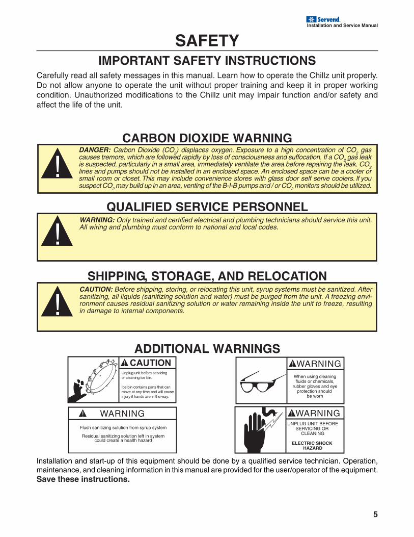
SAFETYIMPORTANT SAFETY INSTRUCTIONS
Carefully read all safety messages in this manual. Learn how to operate the Chillz unit properly.Do not allow anyone to operate the unit without proper training and keep it in proper workingcondition. Unauthorized modifications to the Chillz unit may impair function and/or safety andaffect the life of the unit.
CARBON DIOXIDE WARNING
QUALIFIED SERVICE PERSONNEL
SHIPPING, STORAGE, AND RELOCATION
ADDITIONAL WARNINGS
Installation and start-up of this equipment should be done by a qualified service technician. Operation,maintenance, and cleaning information in this manual are provided for the user/operator of the equipment.Save these instructions.
DANGER: Carbon Dioxide (CO2) displaces oxygen. Exposure to a high concentration of CO2 gascauses tremors, which are followed rapidly by loss of consciousness and suffocation. If a CO2 gas leakis suspected, particularly in a small area, immediately ventilate the area before repairing the leak. CO2lines and pumps should not be installed in an enclosed space. An enclosed space can be a cooler orsmall room or closet. This may include convenience stores with glass door self serve coolers. If yoususpect CO2 may build up in an area, venting of the B-I-B pumps and / or CO2 monitors should be utilized.
WARNING: Only trained and certified electrical and plumbing technicians should service this unit.All wiring and plumbing must conform to national and local codes.
CAUTION: Before shipping, storing, or relocating this unit, syrup systems must be sanitized. Aftersanitizing, all liquids (sanitizing solution and water) must be purged from the unit. A freezing envi-ronment causes residual sanitizing solution or water remaining inside the unit to freeze, resultingin damage to internal components.
6
Installation and Service Manual
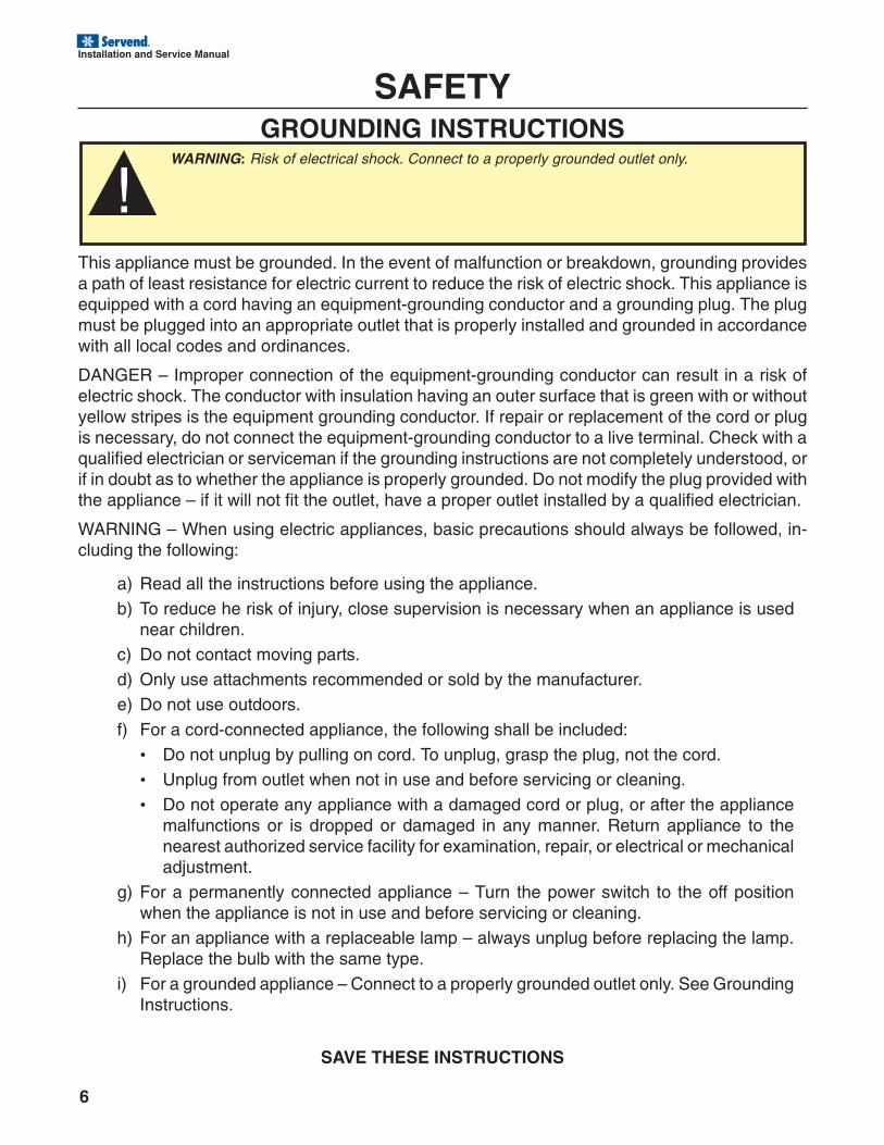
GROUNDING INSTRUCTIONS
SAFETY
This appliance must be grounded. In the event of malfunction or breakdown, grounding providesa path of least resistance for electric current to reduce the risk of electric shock. This appliance isequipped with a cord having an equipment-grounding conductor and a grounding plug. The plugmust be plugged into an appropriate outlet that is properly installed and grounded in accordancewith all local codes and ordinances.
DANGER – Improper connection of the equipment-grounding conductor can result in a risk ofelectric shock. The conductor with insulation having an outer surface that is green with or withoutyellow stripes is the equipment grounding conductor. If repair or replacement of the cord or plugis necessary, do not connect the equipment-grounding conductor to a live terminal. Check with aqualified electrician or serviceman if the grounding instructions are not completely understood, orif in doubt as to whether the appliance is properly grounded. Do not modify the plug provided withthe appliance – if it will not fit the outlet, have a proper outlet installed by a qualified electrician.
WARNING – When using electric appliances, basic precautions should always be followed, in-cluding the following:
a) Read all the instructions before using the appliance.b) To reduce he risk of injury, close supervision is necessary when an appliance is used
near children.c) Do not contact moving parts.d) Only use attachments recommended or sold by the manufacturer.e) Do not use outdoors.
f) For a cord-connected appliance, the following shall be included:• Do not unplug by pulling on cord. To unplug, grasp the plug, not the cord.• Unplug from outlet when not in use and before servicing or cleaning.• Do not operate any appliance with a damaged cord or plug, or after the appliance
malfunctions or is dropped or damaged in any manner. Return appliance to thenearest authorized service facility for examination, repair, or electrical or mechanicaladjustment.
g) For a permanently connected appliance – Turn the power switch to the off positionwhen the appliance is not in use and before servicing or cleaning.
h) For an appliance with a replaceable lamp – always unplug before replacing the lamp.Replace the bulb with the same type.
i) For a grounded appliance – Connect to a properly grounded outlet only. See GroundingInstructions.
SAVE THESE INSTRUCTIONS
WARNING: Risk of electrical shock. Connect to a properly grounded outlet only.
Installation and Service Manual
7
SAFETYGENERAL SAFETY RULES
• Carefully read the whole instruction manual.
• The connection to the electricity mains must complywith the current safety standards in the user’s country.
• The machine must be connected to an electric outletthat is:- compatible with the plug provided with the ma-
chine;- of dimensions conforming to the data shown on
the rating plate on the side of the machine.- properly grounded;- connected to a system provided with a differen-
tial switch and circuit breaker.
• The power cord must not be:- allowed to come into contact with any kind of liq-
uid: danger of electric shocks and/or fire;- crushed and/or brought into contact with sharp
surfaces;- used to move the machine;- used if it shows any damage;- handled with damp or wet hands;- wound into a coil when the machine is on.- tampered with.
• DO NOT:- install the machine in a manner other than that
described in Chap. 5.- Install the machine in a place where it may be
exposed to sprays of water.- use the machine near inflammable and/or explo-
sive substances.- leave plastic bags, polystyrene, nails etc. within
children’s reach, since they are potential sourcesof danger.
- allow children to play near the machine.- use spare parts other than those recommended
by the manufacturer.- make any technical changes to the machine.- immerse the machine in any kind of liquid.- spray
water on the machine to wash it.- use the machine other than as directed in this
manual.- use the machine when not in full possession of
your mental and physical faculties: under the in-fluence of drugs, alcohol, etc.
- install the machine on top of other equipment.- use the machine in an explosive or aggressive
atmosphere or in the presence of a high concen-tration of dust or oily substances suspended inthe air;
- use the machine in a place where there is arisk of fire;
- use the machine to dispense substances that arenot compatible with the machine’s specifications;
• Before cleaning the machine, make sure that it is un-plugged; do not clean the machine with gasoline and/or solvents of any kind.
• Repair work may be performed only by a Service Cen-ter authorized by the Manufacturer and/or specialized,trained personnel.
• Do not obstruct the grill vents on the side of the ma-chine.
• Do not position the machine near heating equipment(stoves or radiators).
• In case of fire, use carbon dioxide (CO2) extinguish-
ers. Do not use water or powder extinguishers.
In the event of improper use, all warranty rights will be for-feited and the manufacturer will accept no liability for injuryor damage to persons and/or property.
The following are to be considered improper use:
- any use other than the intended use and/or withmethods other than those described herein;
- any operation on the machine that is in contrastwith the directions provided herein;
- use of the machine after any components havebeen tampered with and/or safety devices havebeen changed;
- use of the machine after it has undergone repairwith components not authorized by the manu-facturer;
- outdoor installation of the machine.
STOP FUNCTIONSThe machine is shut down by turning off the main switch.
PLATESNone of the plates or labels applied on the machine must be removed, covered or damaged, especiallythose relating to safety.
8
Installation and Service Manual
GENERAL INFORMATIONMANUFACTURER
The manufacturer’s details are shown on the identification plate, illustrated on first and/or last page of the manual.
AUTHORIZED PERSONSTwo types of persons may access the machine for different purposes.
UserA person who has adequate technical training to prepare the products the machine uses to dispense granita, inobservance of current standards of hygiene. After reading this manual, he will be capable of:
• Carrying out normal product loading and/or replacement operations;
• Properly dispensing the product;
• Cleaning and sanitizing the machine.
Specialized technicianA person who has examined this manual and has specific training in the installation, use and servicing of thegranita machine:
• He must be able to carry out repairs in the event of serious faults and be well acquainted with this manual andall the information regarding safety;
• He must be able to understand the contents of the manual and correctly interpret drawings and diagrams;
• He must be familiar with the most important sanitary, accident prevention, technological and safety standards;
• He must have specific experience in servicing granita machines;
• He must know how to behave in case of emergency, where to find individual safety equipment and how to useit properly.
Persons who do not meet the above requirements must not be allowed to use the machine.
LAYOUT OF THE MANUALThe Purchaser must very carefully read the information contained in this manual.
PURPOSE AND CONTENTSThe purpose of this manual is to provide the Purchaser with all the necessary information regarding the installation,maintenance and use of the granita machine.
Before carrying out any operation on the machine, users and specialized technicians must care-fully read the instructions herein.
Should you have any doubts as to the correct interpretation of these instructions, contact the manufacturer torequest the necessary explanations.
You should not carry out any type of operation until you have read and thoroughly understood thecontents of this manual.
WHO MUST READ THE MANUALThis manual is aimed at users and specialized technicians.
Users must not attempt to carry out any operations restricted to qualified technicians.
The manufacturer will not be liable for any damage or injury caused as a result of failure to comply with this rule.The instruction manual is an integral part of the product purchased and must therefore be handed over to anysubsequent owners.
Installation and Service Manual
9
GENERAL INFORMATIONHOW TO KEEP THE MANUAL
This instruction manual must be kept in the immediate vicinity of the machine. Due precautions should be taken toensure that the manual is maintained intact and legible over time:
• Use the manual in such a way as to avoid damaging any of its contents.
• Do not for any reason remove, tear or rewrite parts of the manual.
• Keep the manual in a place that is protected against humidity and heat in order to preserve the quality of theprint and the legibility of all its parts.
If the present instruction manual is damaged or lost, another copy should be immediately requestedfrom the manufacturer or authorized distributor in the user’s country.
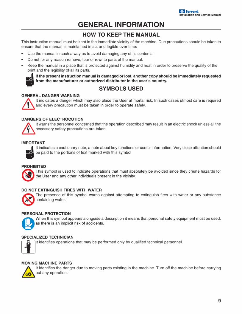
SYMBOLS USEDGENERAL DANGER WARNING
It indicates a danger which may also place the User at mortal risk. In such cases utmost care is requiredand every precaution must be taken in order to operate safely.
DANGERS OF ELECTROCUTIONIt warns the personnel concerned that the operation described may result in an electric shock unless all thenecessary safety precautions are taken
IMPORTANTIt indicates a cautionary note, a note about key functions or useful information. Very close attention shouldbe paid to the portions of text marked with this symbol
PROHIBITEDThis symbol is used to indicate operations that must absolutely be avoided since they create hazards forthe User and any other individuals present in the vicinity.
DO NOT EXTINGUISH FIRES WITH WATERThe presence of this symbol warns against attempting to extinguish fires with water or any substancecontaining water.
PERSONAL PROTECTIONWhen this symbol appears alongside a description it means that personal safety equipment must be used,as there is an implicit risk of accidents.
SPECIALIZED TECHNICIANIt identifies operations that may be performed only by qualified technical personnel.
MOVING MACHINE PARTSIt identifies the danger due to moving parts existing in the machine. Turn off the machine before carryingout any operation.
10
Installation and Service Manual
INSTALLATIONAll of the operations described may be carried out exclusively by specialized technicians, who must orga-nize all the operational sequences and use suitable equipment, in strict compliance with the applicableregulations currently in force. The machine must be installed indoors in a well-lit and well-ventilated roomwith a firm, solid, level floor (slope less than 2°).
The machine is of the attended type, and must be installed in places where it can be monitored by trainedpersonnel. The machine may only operate in places with an ambient temperature ranging between 20°Cand 32°C.
LIST OF ACCESSORIES PROVIDEDThe following items of equipment are supplied with thestandard model of the machine:
• Padlock and key (1 for each bowl of the granitamachine): to lock the bowl during normal use andprevent its opening by unauthorized persons.
• Food Grade Lubricant: to lubricate all of the partsindicated in this manual after washing and saniti-zation operations.
POSITIONINGThe installer must check that:
• the site has been duly prepared for machine instal-lation;
• the surface the machine will be installed on is firm,flat and solid;
• the room is adequately lit, ventilated and hygienicand an electric outlet is within easy reach.
The figure indicates the space required for accessing:
• the control panel on the right side;
• machine parts so that they may be serviced in theevent of a fault.
After positioning the packing container in the vicinity ofthe installation site, proceed as follows:
1. cut the straps securing the box;
2. lift the cardboard box;
3. then lift the machine and position it on the prepared site.
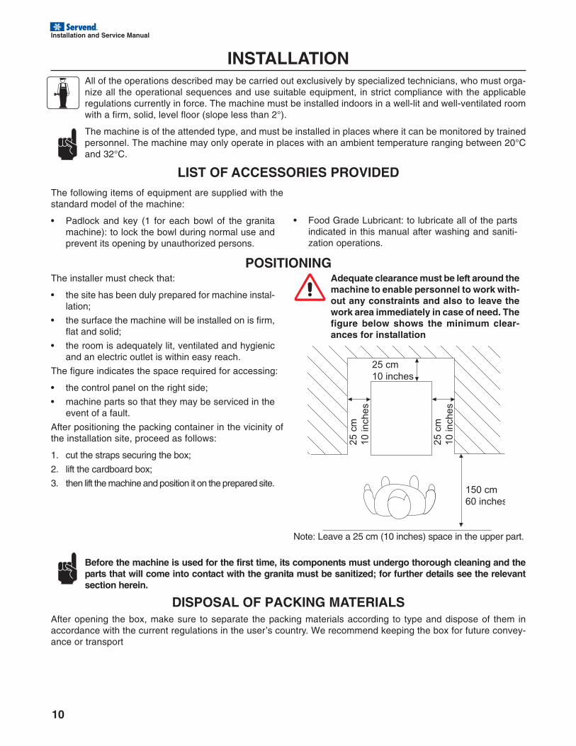
Adequate clearance must be left around themachine to enable personnel to work with-out any constraints and also to leave thework area immediately in case of need. Thefigure below shows the minimum clear-ances for installation
Note: Leave a 25 cm (10 inches) space in the upper part.
150 cm
60 inches
25 c
m
10 inches
25 c
m
10 inches
25 cm
10 inches
Before the machine is used for the first time, its components must undergo thorough cleaning and theparts that will come into contact with the granita must be sanitized; for further details see the relevantsection herein.
DISPOSAL OF PACKING MATERIALSAfter opening the box, make sure to separate the packing materials according to type and dispose of them inaccordance with the current regulations in the user’s country. We recommend keeping the box for future convey-ance or transport
Installation and Service Manual
11
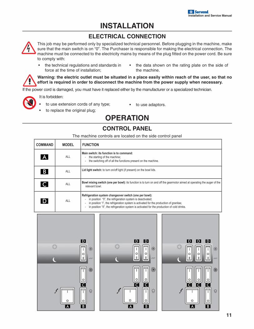
COMMAND MODEL FUNCTION
ALLMain switch: its function is to command:
- the starting of the machine;
- the switching off of all the functions present on the machine.
ALL Lid light switch: to turn on/off light (if present) on the bowl lids.
ALLBowl mixing switch (one per bowl): its function is to turn on and off the gearmotor aimed at operating the auger of the
relevant bowl.
ALL
Refrigeration system changeover switch (one per bowl):
- in position “0”, the refrigeration system is deactivated;
- in position “I”, the refrigeration system is activated for the production of granitas;
- in position “II”, the refrigeration system is activated for the production of cold drinks.
INSTALLATIONELECTRICAL CONNECTION
This job may be performed only by specialized technical personnel. Before plugging in the machine, makesure that the main switch is on “0”. The Purchaser is responsible for making the electrical connection. Themachine must be connected to the electricity mains by means of the plug fitted on the power cord. Be sureto comply with:
• the technical regulations and standards inforce at the time of installation;
• the data shown on the rating plate on the side ofthe machine.
Warning: the electric outlet must be situated in a place easily within reach of the user, so that noeffort is required in order to disconnect the machine from the power supply when necessary.
If the power cord is damaged, you must have it replaced either by the manufacturer or a specialized technician.
It is forbidden:
• to use extension cords of any type;
• to replace the original plug;
OPERATIONCONTROL PANEL
The machine controls are located on the side control panel
• to use adaptors.
12
Installation and Service Manual
OPERATIONUSE OF THE MACHINE
The machine you have purchased is intended to prepare granita and cold drinks.
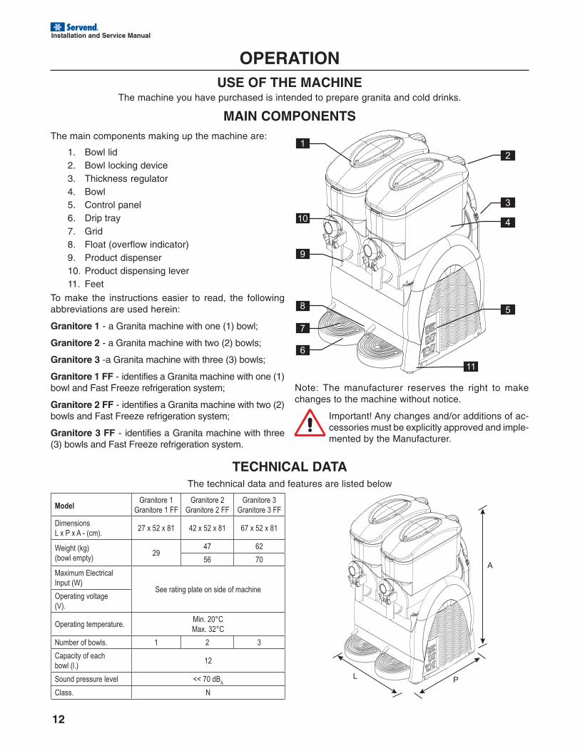
MAIN COMPONENTSThe main components making up the machine are:
1. Bowl lid2. Bowl locking device3. Thickness regulator4. Bowl5. Control panel6. Drip tray7. Grid8. Float (overflow indicator)9. Product dispenser10. Product dispensing lever11. Feet
To make the instructions easier to read, the followingabbreviations are used herein:
Granitore 1 - a Granita machine with one (1) bowl;
Granitore 2 - a Granita machine with two (2) bowls;
Granitore 3 -a Granita machine with three (3) bowls;
Granitore 1 FF - identifies a Granita machine with one (1)bowl and Fast Freeze refrigeration system;
Granitore 2 FF - identifies a Granita machine with two (2)bowls and Fast Freeze refrigeration system;
Granitore 3 FF - identifies a Granita machine with three(3) bowls and Fast Freeze refrigeration system.
1
10
9
2
3
4
5
7
6
11
8
TECHNICAL DATAThe technical data and features are listed below
Note: The manufacturer reserves the right to makechanges to the machine without notice.
Important! Any changes and/or additions of ac-cessories must be explicitly approved and imple-mented by the Manufacturer.
ModelGranitore 1
Granitore 1 FF
Granitore 2
Granitore 2 FF
Granitore 3
Granitore 3 FF
Dimensions
L x P x A - (cm).27 x 52 x 81 42 x 52 x 81 67 x 52 x 81
Weight (kg)
(bowl empty)29
47 62
56 70
Maximum Electrical
Input (W)See rating plate on side of machine
Operating voltage
(V).
Operating temperature.Min. 20°C
Max. 32°C
Number of bowls. 1 2 3
Capacity of each
bowl (l.)12
Sound pressure level << 70 dBA
Class. N
A
PL
Installation and Service Manual
13
OPERATIONAll the operations described may be carried out exclusively by technicians who are also specialized in the liftingand handling of packed or unpacked machines. They must organize all the operational sequences and usesuitable equipment, according to the characteristics and weight of the object to be handled and in strict compli-ance with the applicable regulations currently in force.
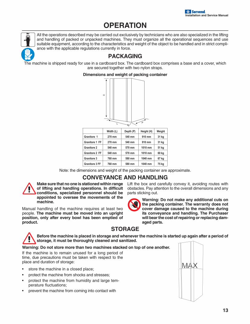
PACKAGINGThe machine is shipped ready for use in a cardboard box. The cardboard box comprises a base and a cover, which
are secured together with two nylon straps.
Dimensions and weight of packing container
Width (L) Depth (P) Height (H) Weight
Granitore 1 270 mm 540 mm 910 mm 31 kg
Granitore 1 FF 270 mm 540 mm 910 mm 31 kg
Granitore 2 540 mm 570 mm 1010 mm 51 kg
Granitore 2 FF 540 mm 570 mm 1010 mm 60 kg
Granitore 3 760 mm 580 mm 1040 mm 67 kg
Granitore 3 FF 760 mm 580 mm 1040 mm 75 kg
Note: the dimensions and weight of the packing container are approximate.
H
PL
CONVEYANCE AND HANDLINGMake sure that no one is stationed within rangeof lifting and handling operations. In difficultconditions, specialized personnel should beappointed to oversee the movements of themachine.
Manual handling of the machine requires at least twopeople. The machine must be moved into an uprightposition, only after every bowl has been emptied ofproduct.
Lift the box and carefully convey it, avoiding routes withobstacles. Pay attention to the overall dimensions and anyparts sticking out.
Warning: Do not make any additional cuts onthe packing container. The warranty does notcover damage caused to the machine duringits conveyance and handling. The Purchaserwill bear the cost of repairing or replacing dam-aged parts.
STORAGEBefore the machine is placed in storage and whenever the machine is started up again after a period ofstorage, it must be thoroughly cleaned and sanitized.
Warning: Do not store more than two machines stacked on top of one another.
MAX
If the machine is to remain unused for a long period oftime, due precautions must be taken with respect to theplace and duration of storage:
• store the machine in a closed place;• protect the machine from shocks and stresses;• protect the machine from humidity and large tem-
perature fluctuations;• prevent the machine from coming into contact with
14
Installation and Service Manual
OPERATIONBefore the machine may be started up for the first time, specialized technical personnel must check that it functionsproperly.
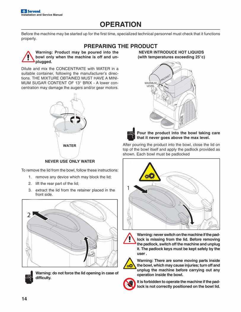
PREPARING THE PRODUCTWarning: Product may be poured into thebowl only when the machine is off and un-plugged.
Dilute and mix the CONCENTRATE with WATER in asuitable container, following the manufacturer’s direc-tions. THE MIXTURE OBTAINED MUST HAVE A MINI-MUM SUGAR CONTENT OF 13° BRIX - A lower con-centration may damage the augers and/or gear motors.
NEVER USE ONLY WATER
To remove the lid from the bowl, follow these instructions:
1. remove any device which may block the lid;
2. lift the rear part of the lid;
3. extract the lid from the retainer placed in thefront side.
NEVER INTRODUCE HOT LIQUIDS(with temperatures exceeding 25°c)
Pour the product into the bowl taking carethat it never goes above the max level.
After pouring the product into the bowl, close the lid ontop of the bowl itself and apply the padlock provided asshown. Each bowl must be padlocked
Warning: never switch on the machine if the pad-lock is missing from the lid. Before removingthe padlock, switch off the machine and unplugit. The padlock keys must be kept safely by theuser .
Warning: There are some moving parts insidethe bowl, which may cause injuries; turn off andunplug the machine before carrying out anyoperation inside the bowl.
It is forbidden to operate the machine if the pad-lock is not correctly positioned on the bowl lid.
Warning: do not force the lid opening in case ofdifficulty.
Installation and Service Manual
15
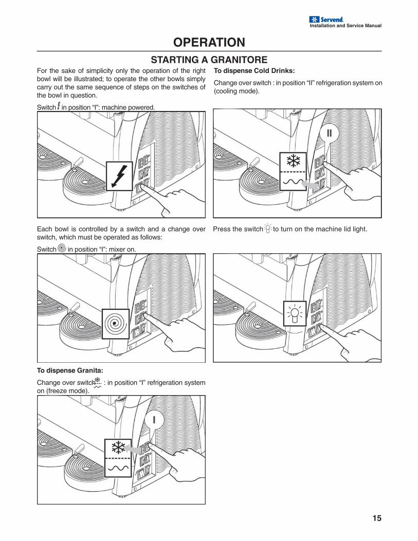
OPERATIONSTARTING A GRANITORE
For the sake of simplicity only the operation of the rightbowl will be illustrated; to operate the other bowls simplycarry out the same sequence of steps on the switches ofthe bowl in question.
Switch in position “I”: machine powered.
Each bowl is controlled by a switch and a change overswitch, which must be operated as follows:
Switch in position “I”: mixer on.
To dispense Granita:
Change over switch : in position “I” refrigeration systemon (freeze mode).
To dispense Cold Drinks:
Change over switch : in position “II” refrigeration system on(cooling mode).
Press the switch to turn on the machine lid light.
16
Installation and Service Manual
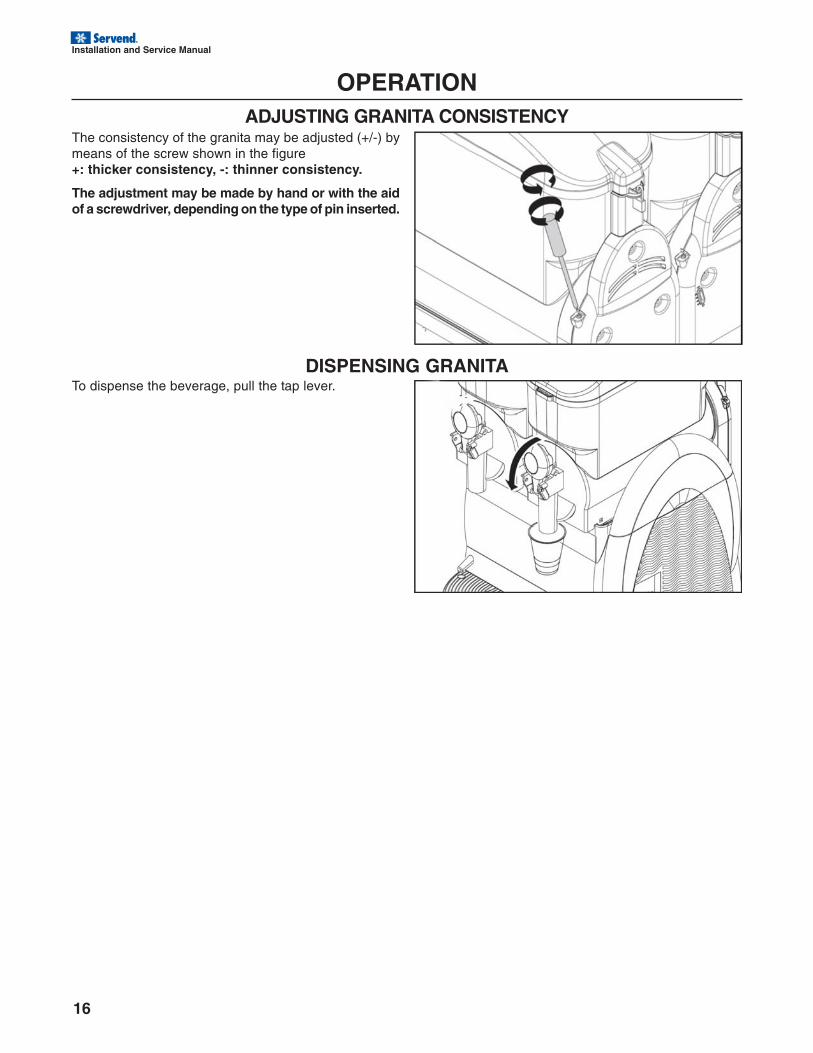
OPERATIONADJUSTING GRANITA CONSISTENCY
The consistency of the granita may be adjusted (+/-) bymeans of the screw shown in the figure+: thicker consistency, -: thinner consistency.
The adjustment may be made by hand or with the aidof a screwdriver, depending on the type of pin inserted.
DISPENSING GRANITATo dispense the beverage, pull the tap lever.
Installation and Service Manual
17
OPERATIONINDICATIONS FOR CORRECT USE
When the level of granita in the bowl is below the mid of themixing auger, in order to prevent the product from becom-ing too thick, it is necessary to stop the refrigeration sys-tem by selecting “O” on the change over switch , or it isnecessary to fill the bowl. For safety reasons, each timeyou fill bowls, switch the mixer off. If the machine isswitched off at night with the bowls even partially full, an icelayer can build up at the surface: this is the natural effect
which results due to the separation of the non-mixed prod-uct. Should this occur, before restarting the machine, re-move the ice layer so as to prevent any mixer damage. Toaccess the THERMOSTAT (cold drink temperature only)and FUSES, remove the side grate on the control panelside, adjust and check as necessary, then fit the grate cor-rectly back in place.
Note: The main supply fuses are optional for models220/240V 50/60 hz.
EMERGENCY SITUATIONSWarning: in every emergency situation, to shut down the machine, firmly press the main switchinto position -0-.
In case of freezing, switch off the machine and contact a service center or specialized technician.
If a fire breaks out, the area must be immediately cleared to make way for trained personnel pro-vided with suitable safety equipment. Always use approved extinguishers, never use water or sub-stances of dubious nature.
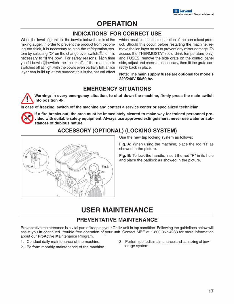
ACCESSORY (OPTIONAL) (LOCKING SYSTEM)Use the new tap locking system as follows:
Fig. A: When using the machine, place the rod “R” asshowed in the picture.
Fig. B: To lock the handle, insert the rod “R” in its holeand place the padlock as showed in the picture.
USER MAINTENANCEPREVENTATIVE MAINTENANCE
Preventative maintenance is a vital part of keeping your Chillz unit in top condition. Following the guidelines below willassist you in continued trouble free operation of your unit. Contact MBE at 1-800-367-4233 for more informationabout our ProActive Maintenance Program.1. Conduct daily maintenance of the machine.2. Perform monthly maintenance of the machine.
3. Perform periodic maintenance and sanitizing of bev-erage system.
18
Installation and Service Manual
USER MAINTENANCEBefore undertaking any cleaning and maintenance of external machine components, make surethat the main switch is positioned on -0- and that the machine is unplugged.
Before performing any cleaning and maintenance operation on the machine, wear the personalprotections (gloves, glasses, etc.), which are recommended by the safety standards in force in thecountry where the machine is used.
When performing the Cleaning and Maintenance operations, follow these instructions:
• wear protection accident-proof gloves;• do not use solvents or inflammable materials;• take care to avoid dispersing liquids in the sur-
rounding area;• do not wash machine components in a dish-
washer;• do not dry parts of the machine in a conven-
tional and/or microwave oven;• do not immerse the machine in water;
• do not expose the machine to direct sprays ofwater;
• for cleaning use only lukewarm water and asuitable sanitizing agent (conforming to currentregulations in the user’s country) that will notrisk damaging machine components;
• on completing work, make sure that all protec-tive covers and guards that have been removedor opened are set back in place and properlysecured.
Cleaning and sanitization are operations that must be performed with utmost care and on a regular basis to guar-antee the quality of the beverages dispensed and compliance with mandatory hygiene standards.
Each bowl must be cleaned and sanitized for a product change at least every 2 (two) days in com-pliance with the current hygiene regulations in the user’s country. The stainless materials, plasticand rubber used to manufacture said parts, as well as their particular shape, make them easy toclean but do not prevent the build-up of germs and mold in the event of inadequate cleaning.
It is forbidden to clean or service the machine when it is plugged in and the main switch is positionedon -1- .
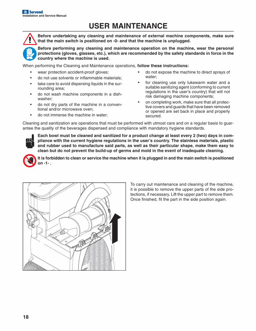
To carry out maintenance and cleaning of the machine,it is possible to remove the upper parts of the side pro-tections, if necessary. Lift the upper part to remove them.Once finished, fit the part in the side position again.
Installation and Service Manual
19
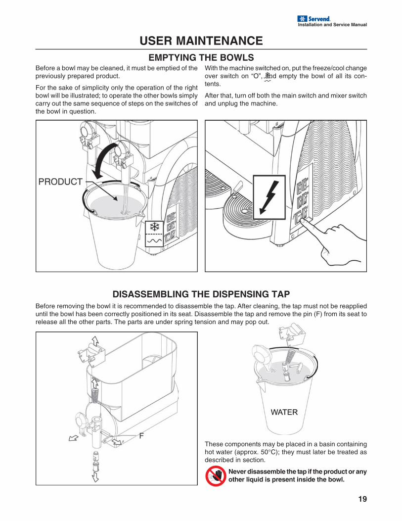
USER MAINTENANCEEMPTYING THE BOWLS
Before a bowl may be cleaned, it must be emptied of thepreviously prepared product.
For the sake of simplicity only the operation of the rightbowl will be illustrated; to operate the other bowls simplycarry out the same sequence of steps on the switches ofthe bowl in question.
DISASSEMBLING THE DISPENSING TAPBefore removing the bowl it is recommended to disassemble the tap. After cleaning, the tap must not be reapplieduntil the bowl has been correctly positioned in its seat. Disassemble the tap and remove the pin (F) from its seat torelease all the other parts. The parts are under spring tension and may pop out.
With the machine switched on, put the freeze/cool changeover switch on “O”, and empty the bowl of all its con-tents.
After that, turn off both the main switch and mixer switchand unplug the machine.
These components may be placed in a basin containinghot water (approx. 50°C); they must later be treated asdescribed in section.
Never disassemble the tap if the product or anyother liquid is present inside the bowl.
20
Installation and Service Manual
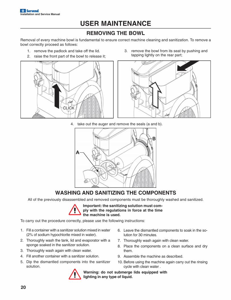
USER MAINTENANCEREMOVING THE BOWL
Removal of every machine bowl is fundamental to ensure correct machine cleaning and sanitization. To remove abowl correctly proceed as follows:
1. remove the padlock and take off the lid.2. raise the front part of the bowl to release it;
3. remove the bowl from its seat by pushing andtapping lightly on the rear part;
4. take out the auger and remove the seals (a and b).
WASHING AND SANITIZING THE COMPONENTSAll of the previously disassembled and removed components must be thoroughly washed and sanitized.
Important: the sanitizing solution must com-ply with the regulations in force at the timethe machine is used.
To carry out the procedure correctly, please use the following instructions:
6. Leave the dismantled components to soak in the so-lution for 30 minutes.
7. Thoroughly wash again with clean water.
8. Place the components on a clean surface and drythem.
9. Assemble the machine as described.
10. Before using the machine again carry out the rinsingcycle with clean water .
1. Fill a container with a sanitizer solution mixed in water(2% of sodium hypochlorite mixed in water).
2. Thoroughly wash the tank, lid and evaporator with asponge soaked in the sanitizer solution.
3. Thoroughly wash again with clean water.
4. Fill another container with a sanitizer solution.
5. Dip the dismantled components into the sanitizersolution.
Warning: do not submerge lids equipped withlighting in any type of liquid.
Installation and Service Manual
21
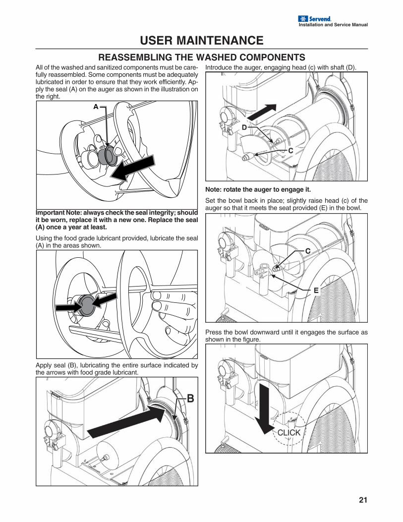
USER MAINTENANCEREASSEMBLING THE WASHED COMPONENTS
All of the washed and sanitized components must be care-fully reassembled. Some components must be adequatelylubricated in order to ensure that they work efficiently. Ap-ply the seal (A) on the auger as shown in the illustration onthe right.
Introduce the auger, engaging head (c) with shaft (D).
Important Note: always check the seal integrity; shouldit be worn, replace it with a new one. Replace the seal(A) once a year at least.
Using the food grade lubricant provided, lubricate the seal(A) in the areas shown.
Apply seal (B), lubricating the entire surface indicated bythe arrows with food grade lubricant.
Note: rotate the auger to engage it.
Set the bowl back in place; slightly raise head (c) of theauger so that it meets the seat provided (E) in the bowl.
Press the bowl downward until it engages the surface asshown in the figure.
22
Installation and Service Manual
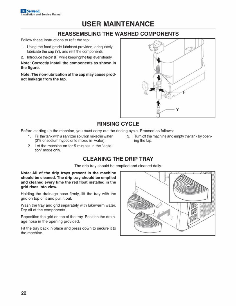
USER MAINTENANCEREASSEMBLING THE WASHED COMPONENTS
Follow these instructions to refit the tap:
1. Using the food grade lubricant provided, adequatelylubricate the cap (Y), and refit the components;
2. Introduce the pin (F) while keeping the tap lever steady.
Note: Correctly install the components as shown inthe figure.
Note: The non-lubrication of the cap may cause prod-uct leakage from the tap.
RINSING CYCLEBefore starting up the machine, you must carry out the rinsing cycle. Proceed as follows:
1. Fill the tank with a sanitizer solution mixed in water(2% of sodium hypoclorite mixed in water).
2. Let the machine on for 5 minutes in the “agita-tion” mode only.
3. Turn off the machine and empty the tank by open-ing the tap.
CLEANING THE DRIP TRAYThe drip tray should be emptied and cleaned daily.
Note: All of the drip trays present in the machineshould be cleaned. The drip tray should be emptiedand cleaned every time the red float installed in thegrid rises into view.
Holding the drainage hose firmly, lift the tray with thegrid on top of it and pull it out.
Wash the tray and grid separately with lukewarm water.Dry all of the components.
Reposition the grid on top of the tray. Position the drain-age hose in the opening provided.
Fit the tray back in place and press down to secure it tothe machine.
Installation and Service Manual
23
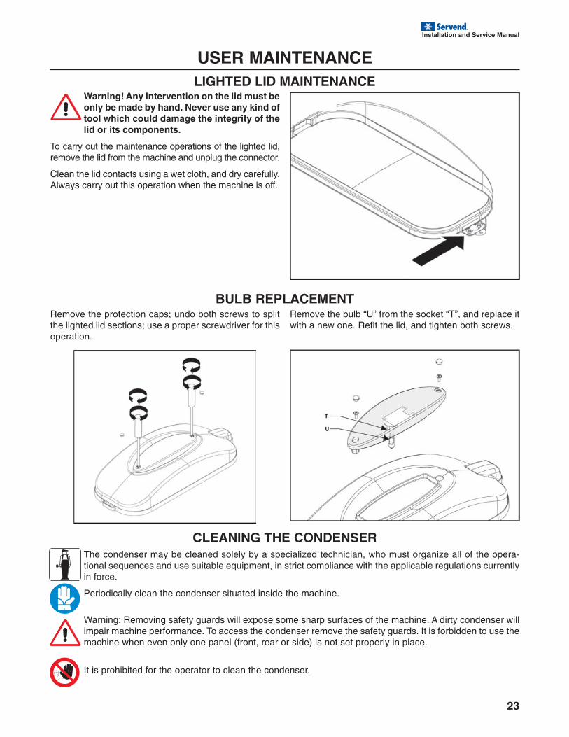
USER MAINTENANCELIGHTED LID MAINTENANCE
Warning! Any intervention on the lid must beonly be made by hand. Never use any kind oftool which could damage the integrity of thelid or its components.
To carry out the maintenance operations of the lighted lid,remove the lid from the machine and unplug the connector.
Clean the lid contacts using a wet cloth, and dry carefully.Always carry out this operation when the machine is off.
BULB REPLACEMENTRemove the protection caps; undo both screws to splitthe lighted lid sections; use a proper screwdriver for thisoperation.
Remove the bulb “U” from the socket “T”, and replace itwith a new one. Refit the lid, and tighten both screws.
CLEANING THE CONDENSERThe condenser may be cleaned solely by a specialized technician, who must organize all of the opera-tional sequences and use suitable equipment, in strict compliance with the applicable regulations currentlyin force.
Periodically clean the condenser situated inside the machine.
Warning: Removing safety guards will expose some sharp surfaces of the machine. A dirty condenser willimpair machine performance. To access the condenser remove the safety guards. It is forbidden to use themachine when even only one panel (front, rear or side) is not set properly in place.
It is prohibited for the operator to clean the condenser.
24
Installation and Service Manual
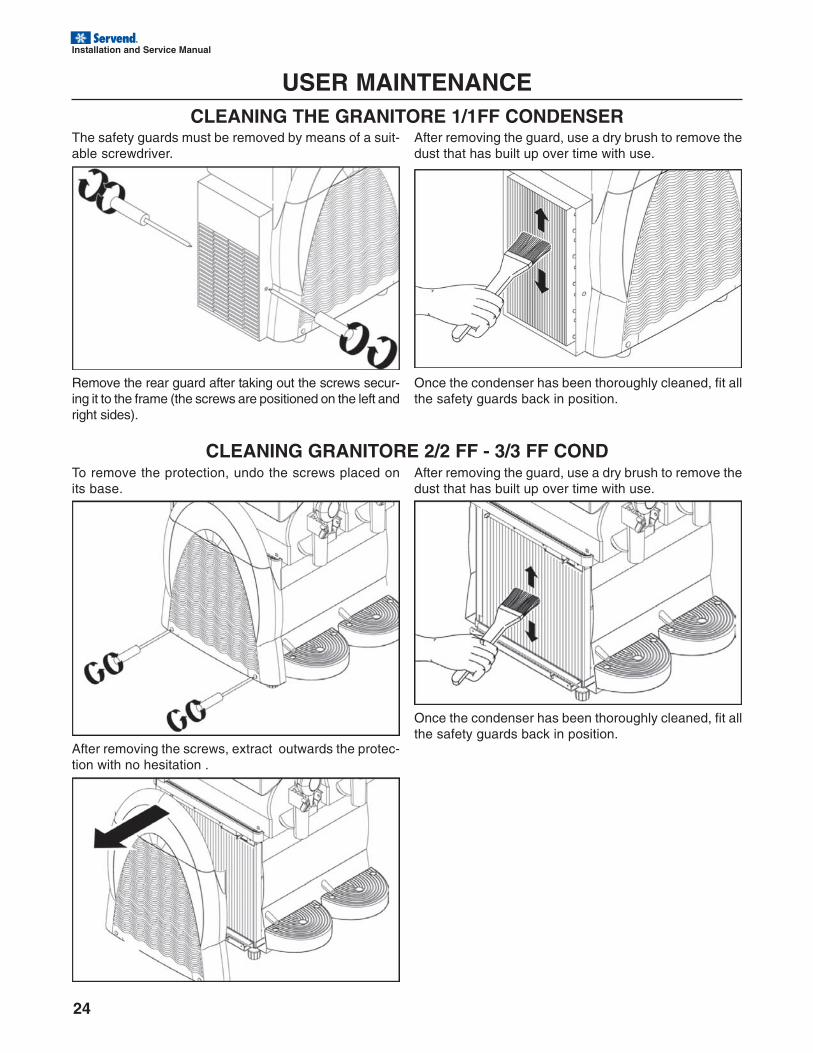
USER MAINTENANCECLEANING THE GRANITORE 1/1FF CONDENSER
The safety guards must be removed by means of a suit-able screwdriver.
Remove the rear guard after taking out the screws secur-ing it to the frame (the screws are positioned on the left andright sides).
After removing the guard, use a dry brush to remove thedust that has built up over time with use.
Once the condenser has been thoroughly cleaned, fit allthe safety guards back in position.
CLEANING GRANITORE 2/2 FF - 3/3 FF CONDTo remove the protection, undo the screws placed onits base.
After removing the screws, extract outwards the protec-tion with no hesitation .
After removing the guard, use a dry brush to remove thedust that has built up over time with use.
Once the condenser has been thoroughly cleaned, fit allthe safety guards back in position.
Installation and Service Manual
25
USER MAINTENANCESCRAPPING
Electric and electronic equipment must be disposed of in accordance with European Directive2002/96/Ec.
Such equipment may not be disposed of as normal municipal solid waste but must rather be separatelycollected to optimize recovery and recycling of the materials used to manufacture them.
All products are marked with the crossed out wheeled bin symbol as a reminder of separate collectionobligations. Correct observance of all of the provisions for the disposal of end-of-life products will contribute tosafeguarding the environment.
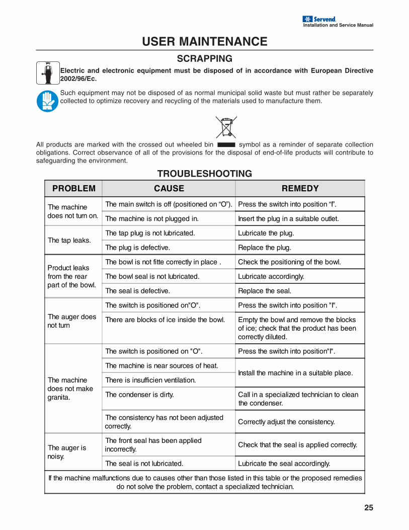
TROUBLESHOOTING
PROBLEM CAUSE REMEDY
The machinedoes not turn on.
The main switch is off (positioned on “O”). Press the switch into position “I”.
The machine is not plugged in. Insert the plug in a suitable outlet.
The tap leaks.The tap plug is not lubricated. Lubricate the plug.
The plug is defective. Replace the plug.
Product leaksfrom the rearpart of the bowl.
The bowl is not fitte correctly in place . Check the positioning of the bowl.
The bowl seal is not lubricated. Lubricate accordingly.
The seal is defective. Replace the seal.
The auger doesnot turn
The switch is positioned on"O". Press the switch into position "I".
There are blocks of ice inside the bowl. Empty the bowl and remove the blocksof ice; check that the product has beencorrectly diluted.
The machinedoes not makegranita.
The switch is positioned on "O". Press the switch into position"I".
The machine is near sources of heat.Install the machine in a suitable place.
There is insufficien ventilation.
The condenser is dirty. Call in a specialized technician to cleanthe condenser.
The consistency has not been adjustedcorrectly.
Correctly adjust the consistency.
The auger isnoisy.
The front seal has been appliedincorrectly.
Check that the seal is applied correctly.
The seal is not lubricated. Lubricate the seal accordingly.
If the machine malfunctions due to causes other than those listed in this table or the proposed remediesdo not solve the problem, contact a specialized technician.
26
Installation and Service Manual
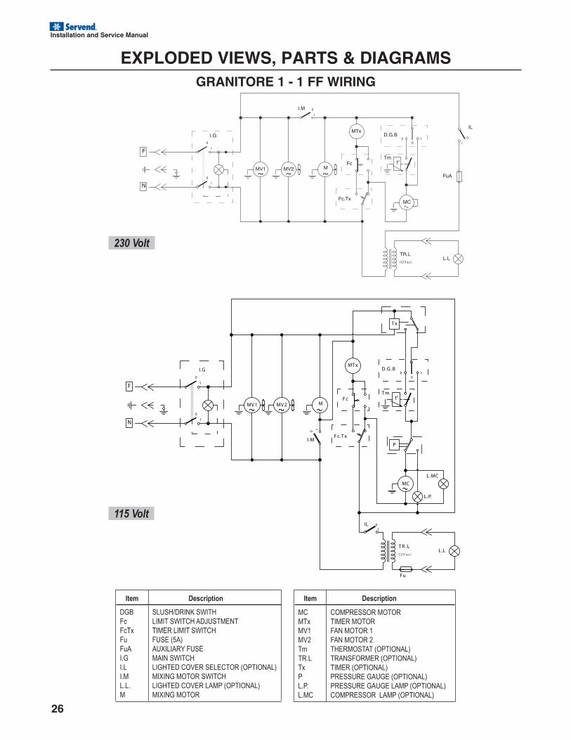
Item Description
DGB
Fc
FcTx
Fu
FuA
I.G
I.L
I.M
L.L.
M
SLUSH/DRINK SWITH
LIMIT SWITCH ADJUSTMENT
TIMER LIMIT SWITCH
FUSE (5A)
AUXILIARY FUSE
MAIN SWITCH
LIGHTED COVER SELECTOR (OPTIONAL)
MIXING MOTOR SWITCH
LIGHTED COVER LAMP (OPTIONAL)
MIXING MOTOR
I.G
0
I
I
0
IL 0
I
T x
L.P.
L.MC
PI.M
0
I
I
0
II
D.G .B
Fu
t°
MC
MT x
F cM
F c.T x
T m
MV 2MV 1
F
N
L.LT R .L
(12 V a.c.)
230 Volt
115 Volt
Item Description
MC
MTx
MV1
MV2
Tm
TR.L
Tx
P
L.P.
L.MC
COMPRESSOR MOTOR
TIMER MOTOR
FAN MOTOR 1
FAN MOTOR 2
THERMOSTAT (OPTIONAL)
TRANSFORMER (OPTIONAL)
TIMER (OPTIONAL)
PRESSURE GAUGE (OPTIONAL)
PRESSURE GAUGE LAMP (OPTIONAL)
COMPRESSOR LAMP (OPTIONAL)
EXPLODED VIEWS, PARTS & DIAGRAMSGRANITORE 1 - 1 FF WIRING
Installation and Service Manual
27
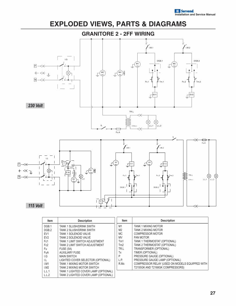
EXPLODED VIEWS, PARTS & DIAGRAMSGRANITORE 2 - 2FF WIRING
Item Description
DGB.1
DGB.2
EV1
EV2
Fc1
Fc2
Fu
FuA
I.G
I.L
I.M1
I.M2
L.L.1
L.L.2
TANK 1 SLUSH/DRINK SWITH
TANK 2 SLUSH/DRINK SWITH
TANK 1 SOLENOID VALVE
TANK 2 SOLENOID VALVE
TANK 1 LIMIT SWITCH ADJUSTMENT
TANK 2 LIMIT SWITCH ADJUSTMENT
FUSE (5A)
AUXILIARY FUSE
MAIN SWITCH
LIGHTED COVER SELECTOR (OPTIONAL)
TANK 1 MIXING MOTOR SWITCH
TANK 2 MIXING MOTOR SWITCH
TANK 1 LIGHTED COVER LAMP (OPTIONAL)
TANK 2 LIGHTED COVER LAMP (OPTIONAL)
Item Description
M1
M2
MC
MV
Tm1
Tm2
TR.L
Tx
P
L.P.
R.Mc
TANK 1 MIXING MOTOR
TANK 2 MIXING MOTOR
COMPRESSOR MOTOR
FAN MOTOR
TANK 1 THERMOSTAT (OPTIONAL)
TANK 2 THERMOSTAT (OPTIONAL)
TRANSFORMER (OPTIONAL)
TIMER (OPTIONAL)
PRESSURE GAUGE (OPTIONAL)
PRESSURE GAUGE LAMP (OPTIONAL)
COMPRESSOR RELAY (USED ON MODELS EQUIPPED WITH
T2155GK AND T2168GK COMPRESSORS)
T x
DG B .2
E V 2
F c.2 T m.2
DG B .1
E V 1
F c.1 T m.1
I
00
I
IIII II
(12Va.c.)
T R .L
L.L.1 L.L.2
Fu.A
IL
L.P.
P
R .McMV
M2M1
I.M.2I.M.1
MC
I.G
0
I
I
0
F
N
230 Volt
115 Volt
28
Installation and Service Manual
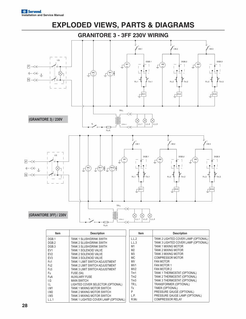
EXPLODED VIEWS, PARTS & DIAGRAMSGRANITORE 3 - 3FF 230V WIRING
(GRANITORE 3FF) / 230V
(GRANITORE 3) / 230V
Item Description Item Description
DGB.1
DGB.2
DGB.3
EV1
EV2
EV3
Fc1
Fc2
Fc3
Fu
FuA
I.G
I.L
I.M1
I.M2
I.M3
L.L.1
TANK 1 SLUSH/DRINK SWITH
TANK 2 SLUSH/DRINK SWITH
TANK 3 SLUSH/DRINK SWITH
TANK 1 SOLENOID VALVE
TANK 2 SOLENOID VALVE
TANK 3 SOLENOID VALVE
TANK 1 LIMIT SWITCH ADJUSTMENT
TANK 2 LIMIT SWITCH ADJUSTMENT
TANK 3 LIMIT SWITCH ADJUSTMENT
FUSE (5A)
AUXILIARY FUSE
MAIN SWITCH
LIGHTED COVER SELECTOR (OPTIONAL)
TANK 1 MIXING MOTOR SWITCH
TANK 2 MIXING MOTOR SWITCH
TANK 3 MIXING MOTOR SWITCH
TANK 1 LIGHTED COVER LAMP (OPTIONAL)
L.L.2
L.L.3
M1
M2
M3
MC
MV
MV1
MV2
Tm1
Tm2
Tm3
TR.L
Tx
P
L.P.
R.Mc
TANK 2 LIGHTED COVER LAMP (OPTIONAL)
TANK 3 LIGHTED COVER LAMP (OPTIONAL)
TANK 1 MIXING MOTOR
TANK 2 MIXING MOTOR
TANK 3 MIXING MOTOR
COMPRESSOR MOTOR
FAN MOTOR
FAN MOTOR 1
FAN MOTOR 2
TANK 1 THERMOSTAT (OPTIONAL)
TANK 2 THERMOSTAT (OPTIONAL)
TANK 3 THERMOSTAT (OPTIONAL)
TRANSFORMER (OPTIONAL)
TIMER (OPTIONAL)
PRESSURE GAUGE (OPTIONAL)
PRESSURE GAUGE LAMP (OPTIONAL)
COMPRESSOR RELAY
Installation and Service Manual
29
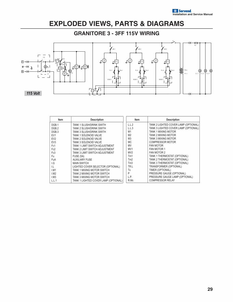
EXPLODED VIEWS, PARTS & DIAGRAMSGRANITORE 3 - 3FF 115V WIRING
I
0 0
I
T m.1F c.1
E V 1
DG B .1
I
0
DG B .3
E V 3
F c.3 T m.3T m.2F c.2
E V 2
DG B .2
T x
0
I
I
0
I.G
I.M.1 I.M.2
M2 M3
I.M.3
L.P.
IL
Fu
L.L.2L.L.1
T R .L
(12Va.c.)
I I III II II
L.L.3
Item Description Item Description
DGB.1
DGB.2
DGB.3
EV1
EV2
EV3
Fc1
Fc2
Fc3
Fu
FuA
I.G
I.L
I.M1
I.M2
I.M3
L.L.1
TANK 1 SLUSH/DRINK SWITH
TANK 2 SLUSH/DRINK SWITH
TANK 3 SLUSH/DRINK SWITH
TANK 1 SOLENOID VALVE
TANK 2 SOLENOID VALVE
TANK 3 SOLENOID VALVE
TANK 1 LIMIT SWITCH ADJUSTMENT
TANK 2 LIMIT SWITCH ADJUSTMENT
TANK 3 LIMIT SWITCH ADJUSTMENT
FUSE (5A)
AUXILIARY FUSE
MAIN SWITCH
LIGHTED COVER SELECTOR (OPTIONAL)
TANK 1 MIXING MOTOR SWITCH
TANK 2 MIXING MOTOR SWITCH
TANK 3 MIXING MOTOR SWITCH
TANK 1 LIGHTED COVER LAMP (OPTIONAL)
L.L.2
L.L.3
M1
M2
M3
MC
MV
MV1
MV2
Tm1
Tm2
Tm3
TR.L
Tx
P
L.P.
R.Mc
TANK 2 LIGHTED COVER LAMP (OPTIONAL)
TANK 3 LIGHTED COVER LAMP (OPTIONAL)
TANK 1 MIXING MOTOR
TANK 2 MIXING MOTOR
TANK 3 MIXING MOTOR
COMPRESSOR MOTOR
FAN MOTOR
FAN MOTOR 1
FAN MOTOR 2
TANK 1 THERMOSTAT (OPTIONAL)
TANK 2 THERMOSTAT (OPTIONAL)
TANK 3 THERMOSTAT (OPTIONAL)
TRANSFORMER (OPTIONAL)
TIMER (OPTIONAL)
PRESSURE GAUGE (OPTIONAL)
PRESSURE GAUGE LAMP (OPTIONAL)
COMPRESSOR RELAY
115 Volt
30
Installation and Service Manual
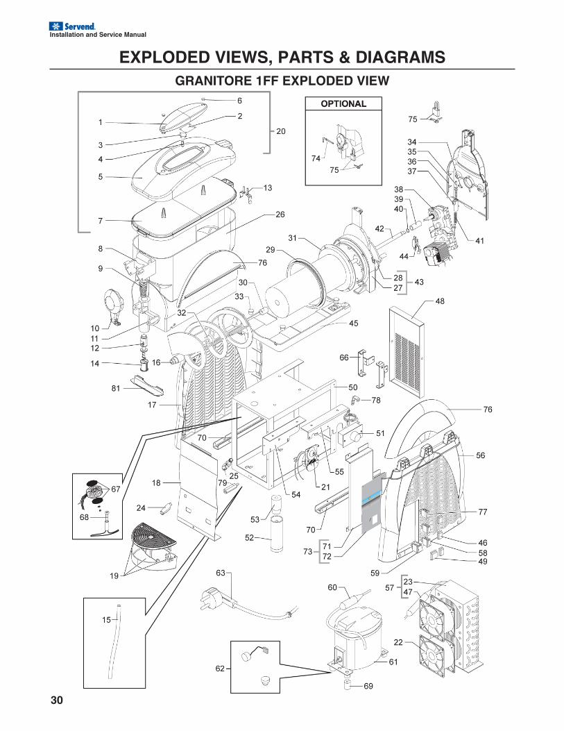
EXPLODED VIEWS, PARTS & DIAGRAMSGRANITORE 1FF EXPLODED VIEW
Installation and Service Manual
31
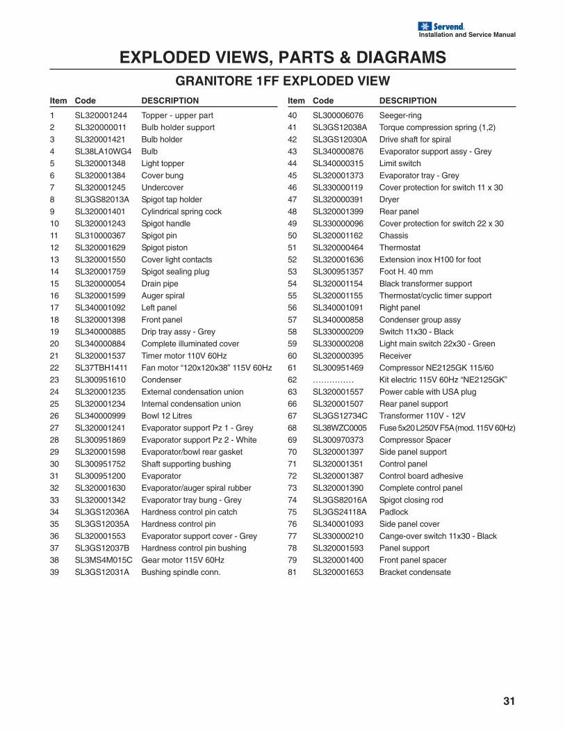
EXPLODED VIEWS, PARTS & DIAGRAMSGRANITORE 1FF EXPLODED VIEW
Item Code DESCRIPTION
1 SL320001244 Topper - upper part2 SL320000011 Bulb holder support
3 SL320001421 Bulb holder4 SL38LA10WG4 Bulb5 SL320001348 Light topper
6 SL320001384 Cover bung7 SL320001245 Undercover8 SL3GS82013A Spigot tap holder
9 SL320001401 Cylindrical spring cock10 SL320001243 Spigot handle11 SL310000367 Spigot pin
12 SL320001629 Spigot piston13 SL320001550 Cover light contacts14 SL320001759 Spigot sealing plug
15 SL320000054 Drain pipe16 SL320001599 Auger spiral17 SL340001092 Left panel
18 SL320001398 Front panel19 SL340000885 Drip tray assy - Grey20 SL340000884 Complete illuminated cover
21 SL320001537 Timer motor 110V 60Hz22 SL37TBH1411 Fan motor “120x120x38” 115V 60Hz23 SL300951610 Condenser
24 SL320001235 External condensation union25 SL320001234 Internal condensation union26 SL340000999 Bowl 12 Litres
27 SL320001241 Evaporator support Pz 1 - Grey28 SL300951869 Evaporator support Pz 2 - White29 SL320001598 Evaporator/bowl rear gasket
30 SL300951752 Shaft supporting bushing31 SL300951200 Evaporator32 SL320001630 Evaporator/auger spiral rubber
33 SL320001342 Evaporator tray bung - Grey34 SL3GS12036A Hardness control pin catch35 SL3GS12035A Hardness control pin
36 SL320001553 Evaporator support cover - Grey37 SL3GS12037B Hardness control pin bushing38 SL3MS4M015C Gear motor 115V 60Hz
39 SL3GS12031A Bushing spindle conn.
Item Code DESCRIPTION
40 SL300006076 Seeger-ring41 SL3GS12038A Torque compression spring (1,2)
42 SL3GS12030A Drive shaft for spiral43 SL340000876 Evaporator support assy - Grey44 SL340000315 Limit switch
45 SL320001373 Evaporator tray - Grey46 SL330000119 Cover protection for switch 11 x 3047 SL320000391 Dryer
48 SL320001399 Rear panel49 SL330000096 Cover protection for switch 22 x 3050 SL320001162 Chassis
51 SL320000464 Thermostat52 SL320001636 Extension inox H100 for foot53 SL300951357 Foot H. 40 mm
54 SL320001154 Black transformer support55 SL320001155 Thermostat/cyclic timer support56 SL340001091 Right panel
57 SL340000858 Condenser group assy58 SL330000209 Switch 11x30 - Black59 SL330000208 Light main switch 22x30 - Green
60 SL320000395 Receiver61 SL300951469 Compressor NE2125GK 115/6062 …………… Kit electric 115V 60Hz “NE2125GK”
63 SL320001557 Power cable with USA plug66 SL320001507 Rear panel support67 SL3GS12734C Transformer 110V - 12V
68 SL38WZC0005 Fuse 5x20 L250V F5A (mod. 115V 60Hz)69 SL300970373 Compressor Spacer70 SL320001397 Side panel support
71 SL320001351 Control panel72 SL320001387 Control board adhesive73 SL320001390 Complete control panel
74 SL3GS82016A Spigot closing rod75 SL3GS24118A Padlock76 SL340001093 Side panel cover
77 SL330000210 Cange-over switch 11x30 - Black78 SL320001593 Panel support79 SL320001400 Front panel spacer
81 SL320001653 Bracket condensate
32
Installation and Service Manual
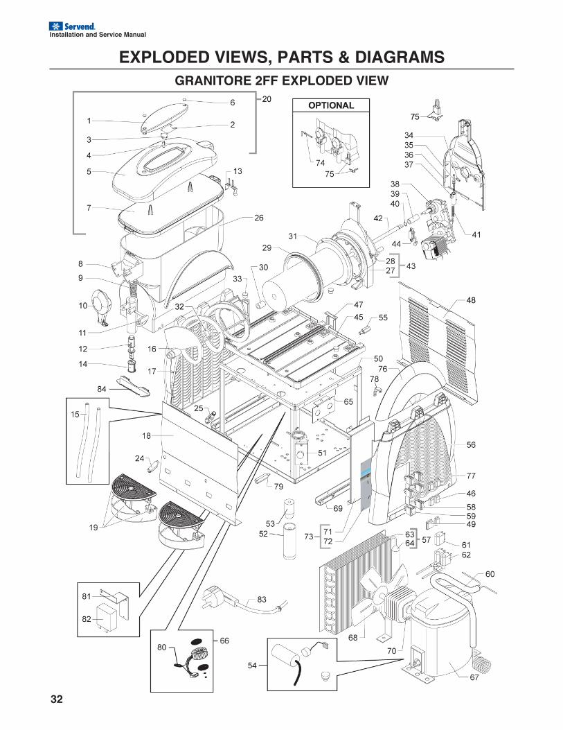
EXPLODED VIEWS, PARTS & DIAGRAMSGRANITORE 2FF EXPLODED VIEW
Installation and Service Manual
33
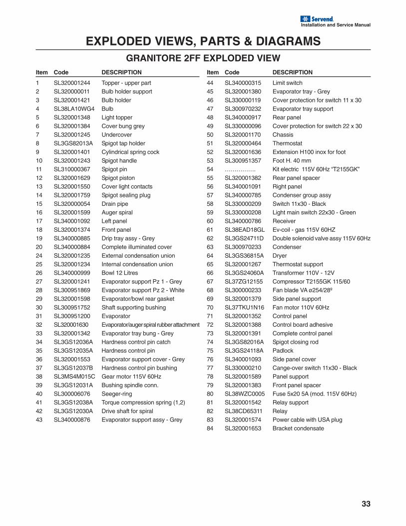
EXPLODED VIEWS, PARTS & DIAGRAMSGRANITORE 2FF EXPLODED VIEW
Item Code DESCRIPTION
1 SL320001244 Topper - upper part2 SL320000011 Bulb holder support
3 SL320001421 Bulb holder4 SL38LA10WG4 Bulb5 SL320001348 Light topper
6 SL320001384 Cover bung grey7 SL320001245 Undercover8 SL3GS82013A Spigot tap holder
9 SL320001401 Cylindrical spring cock10 SL320001243 Spigot handle11 SL310000367 Spigot pin
12 SL320001629 Spigot piston13 SL320001550 Cover light contacts14 SL320001759 Spigot sealing plug
15 SL320000054 Drain pipe16 SL320001599 Auger spiral17 SL340001092 Left panel
18 SL320001374 Front panel19 SL340000885 Drip tray assy - Grey20 SL340000884 Complete illuminated cover
24 SL320001235 External condensation union25 SL320001234 Internal condensation union26 SL340000999 Bowl 12 Litres
27 SL320001241 Evaporator support Pz 1 - Grey28 SL300951869 Evaporator support Pz 2 - White29 SL320001598 Evaporator/bowl rear gasket
30 SL300951752 Shaft supporting bushing31 SL300951200 Evaporator32 SL320001630 Evaporator/auger spiral rubber attachment
33 SL320001342 Evaporator tray bung - Grey34 SL3GS12036A Hardness control pin catch35 SL3GS12035A Hardness control pin
36 SL320001553 Evaporator support cover - Grey37 SL3GS12037B Hardness control pin bushing38 SL3MS4M015C Gear motor 115V 60Hz
39 SL3GS12031A Bushing spindle conn.40 SL300006076 Seeger-ring41 SL3GS12038A Torque compression spring (1,2)
42 SL3GS12030A Drive shaft for spiral43 SL340000876 Evaporator support assy - Grey
Item Code DESCRIPTION
44 SL340000315 Limit switch45 SL320001380 Evaporator tray - Grey
46 SL330000119 Cover protection for switch 11 x 3047 SL300970232 Evaporator tray support48 SL340000917 Rear panel
49 SL330000096 Cover protection for switch 22 x 3050 SL320001170 Chassis51 SL320000464 Thermostat
52 SL320001636 Extension H100 inox for foot53 SL300951357 Foot H. 40 mm54 ……………. Kit electric 115V 60Hz “T2155GK”
55 SL320001382 Rear panel spacer56 SL340001091 Right panel57 SL340000785 Condenser group assy
58 SL330000209 Switch 11x30 - Black59 SL330000208 Light main switch 22x30 - Green60 SL340000786 Receiver
61 SL38EAD18GL Ev-coil - gas 115V 60HZ62 SL3GS24711D Double solenoid valve assy 115V 60Hz63 SL300970233 Condenser
64 SL3GS36815A Dryer65 SL320001267 Thermostat support66 SL3GS24060A Transformer 110V - 12V
67 SL37ZG12155 Compressor T2155GK 115/6068 SL300000233 Fan blade VA ø254/28º69 SL320001379 Side panel support
70 SL37TKU1N16 Fan motor 110V 60Hz71 SL320001352 Control panel72 SL320001388 Control board adhesive
73 SL320001391 Complete control panel74 SL3GS82016A Spigot closing rod75 SL3GS24118A Padlock
76 SL340001093 Side panel cover77 SL330000210 Cange-over switch 11x30 - Black78 SL320001589 Panel support
79 SL320001383 Front panel spacer80 SL38WZC0005 Fuse 5x20 5A (mod. 115V 60Hz)81 SL320001542 Relay support
82 SL38CD65311 Relay83 SL320001574 Power cable with USA plug84 SL320001653 Bracket condensate
34
Installation and Service Manual
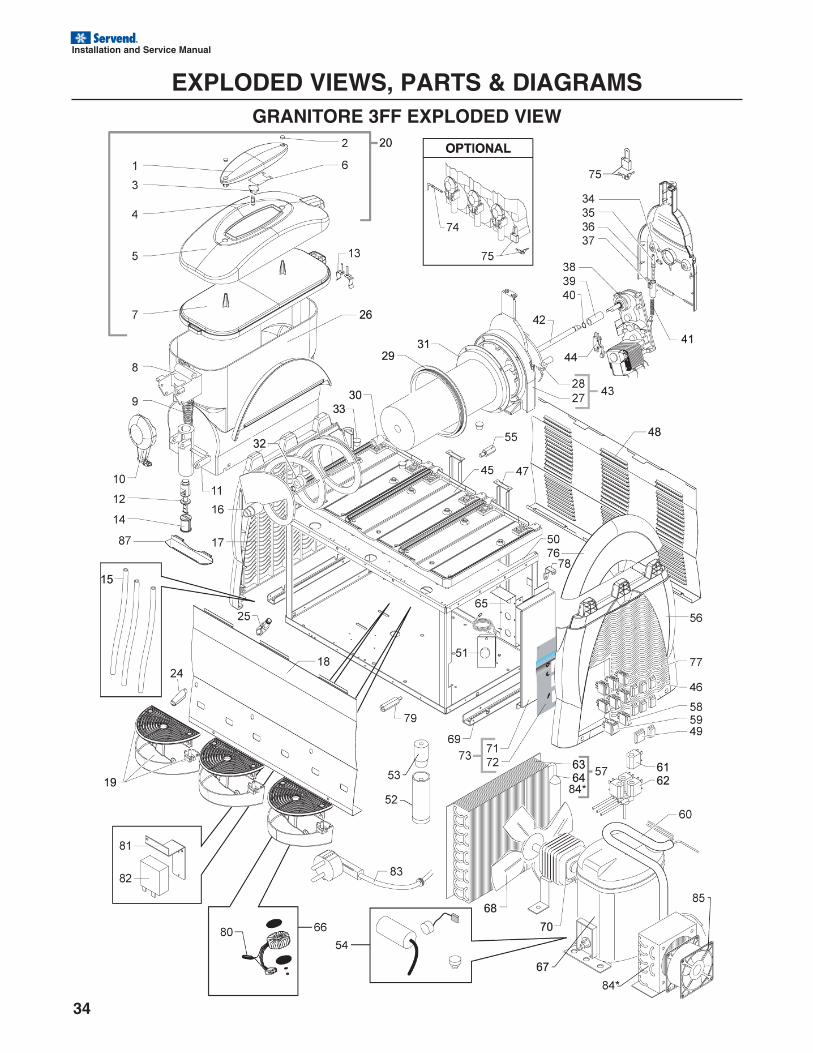
EXPLODED VIEWS, PARTS & DIAGRAMSGRANITORE 3FF EXPLODED VIEW
Installation and Service Manual
35
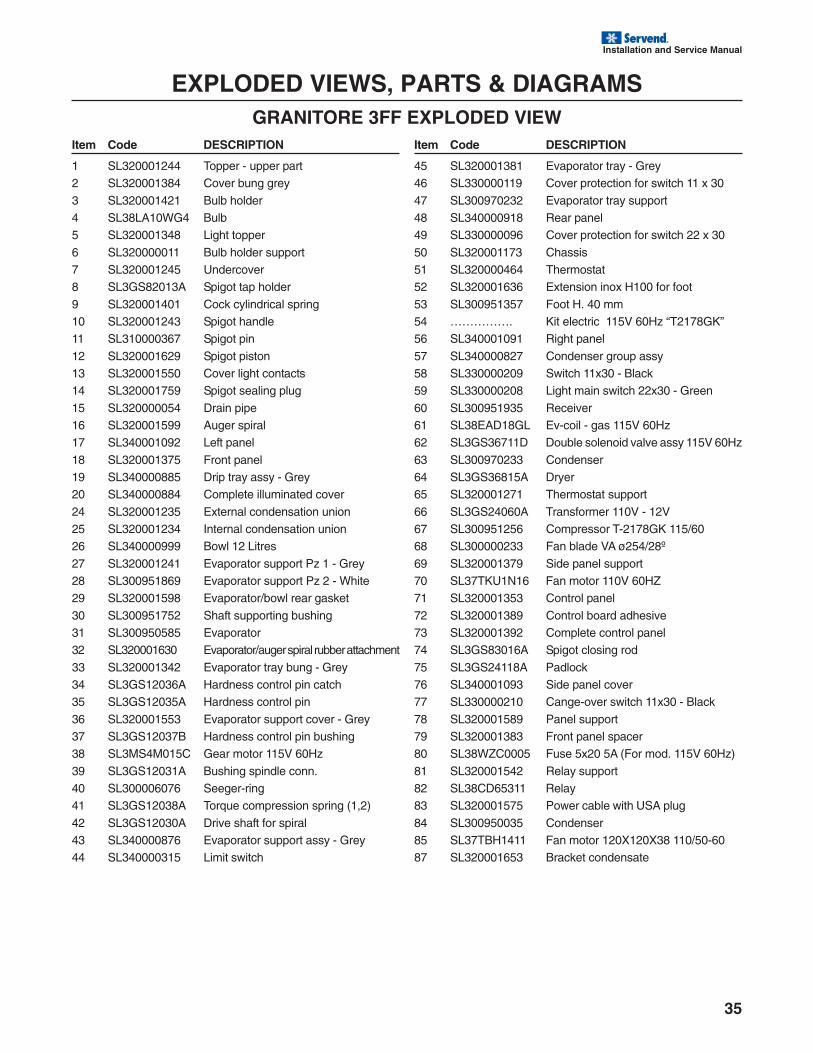
EXPLODED VIEWS, PARTS & DIAGRAMSGRANITORE 3FF EXPLODED VIEW
Item Code DESCRIPTION
1 SL320001244 Topper - upper part2 SL320001384 Cover bung grey
3 SL320001421 Bulb holder4 SL38LA10WG4 Bulb5 SL320001348 Light topper
6 SL320000011 Bulb holder support7 SL320001245 Undercover8 SL3GS82013A Spigot tap holder
9 SL320001401 Cock cylindrical spring10 SL320001243 Spigot handle11 SL310000367 Spigot pin
12 SL320001629 Spigot piston13 SL320001550 Cover light contacts14 SL320001759 Spigot sealing plug
15 SL320000054 Drain pipe16 SL320001599 Auger spiral17 SL340001092 Left panel
18 SL320001375 Front panel19 SL340000885 Drip tray assy - Grey20 SL340000884 Complete illuminated cover
24 SL320001235 External condensation union25 SL320001234 Internal condensation union26 SL340000999 Bowl 12 Litres
27 SL320001241 Evaporator support Pz 1 - Grey28 SL300951869 Evaporator support Pz 2 - White29 SL320001598 Evaporator/bowl rear gasket
30 SL300951752 Shaft supporting bushing31 SL300950585 Evaporator32 SL320001630 Evaporator/auger spiral rubber attachment
33 SL320001342 Evaporator tray bung - Grey34 SL3GS12036A Hardness control pin catch35 SL3GS12035A Hardness control pin
36 SL320001553 Evaporator support cover - Grey37 SL3GS12037B Hardness control pin bushing38 SL3MS4M015C Gear motor 115V 60Hz
39 SL3GS12031A Bushing spindle conn.40 SL300006076 Seeger-ring41 SL3GS12038A Torque compression spring (1,2)
42 SL3GS12030A Drive shaft for spiral43 SL340000876 Evaporator support assy - Grey44 SL340000315 Limit switch
Item Code DESCRIPTION
45 SL320001381 Evaporator tray - Grey46 SL330000119 Cover protection for switch 11 x 30
47 SL300970232 Evaporator tray support48 SL340000918 Rear panel49 SL330000096 Cover protection for switch 22 x 30
50 SL320001173 Chassis51 SL320000464 Thermostat52 SL320001636 Extension inox H100 for foot
53 SL300951357 Foot H. 40 mm54 ……………. Kit electric 115V 60Hz “T2178GK”56 SL340001091 Right panel
57 SL340000827 Condenser group assy58 SL330000209 Switch 11x30 - Black59 SL330000208 Light main switch 22x30 - Green
60 SL300951935 Receiver61 SL38EAD18GL Ev-coil - gas 115V 60Hz62 SL3GS36711D Double solenoid valve assy 115V 60Hz
63 SL300970233 Condenser64 SL3GS36815A Dryer65 SL320001271 Thermostat support
66 SL3GS24060A Transformer 110V - 12V67 SL300951256 Compressor T-2178GK 115/6068 SL300000233 Fan blade VA ø254/28º
69 SL320001379 Side panel support70 SL37TKU1N16 Fan motor 110V 60HZ71 SL320001353 Control panel
72 SL320001389 Control board adhesive73 SL320001392 Complete control panel74 SL3GS83016A Spigot closing rod
75 SL3GS24118A Padlock76 SL340001093 Side panel cover77 SL330000210 Cange-over switch 11x30 - Black
78 SL320001589 Panel support79 SL320001383 Front panel spacer80 SL38WZC0005 Fuse 5x20 5A (For mod. 115V 60Hz)
81 SL320001542 Relay support82 SL38CD65311 Relay83 SL320001575 Power cable with USA plug
84 SL300950035 Condenser85 SL37TBH1411 Fan motor 120X120X38 110/50-6087 SL320001653 Bracket condensate


INDEXB
brixing ....................................... 2
C
Carbon Dioxide ......................... 5Cleaning .................................... 2CO2 ........................................... 4CO2 monitors ............................ 4
D
damage ..................................... 2delivery ...................................... 2Diagrams26, 27, 28, 29, 30, 31, 32, 33, 34, 35Distributor ................................. 2distributor .................................. 2
E
Exploded Views26, 27, 28, 29, 30, 31, 32, 33, 34, 35
F
FOREWORD ............................ 2
I
INSPECTION ............................ 2Installation Date ........................ 2irregularities .............................. 2
M
MBE .......................................... 2Model Number .......................... 2modifications ............................. 5
O
Operation .................................. 5
P
Parts26, 27, 28, 29, 30, 31, 32, 33, 34, 35
Q
Qualified Service Personnel ..... 5
R
Relocation ................................. 5return procedures ..................... 2RGA .......................................... 2
S
SAFETY ........................... 5, 6, 7sanitizing ................................... 4Serial Number ........................... 2Service Agent ............................ 2service assistance .................... 2Service Personnel ..................... 5Shipping .................................... 5Shipping, Storage, Relocation .. 5start-up ...................................... 5Storage ..................................... 5
T
TABLE OF CONTENTS ............ 4Telephone Number ................... 2
U
UNPACKING ............................. 2
W
Warning ..................................... 5WARRANTY ............................. 2WARRANTY INFORMATION ... 2water-to-syrup ratio. See brixing

Manitowoc Beverage Equipment2100 Future Drive Sellersburg, IN 47172-1868Tel: 812.246.7000, 800.367.4233 Fax: 812.246.9922www.manitowocbeverage.com
In accordance with our policy of continuous product development andimprovement, this information is subject to change at any time without notice.
020001173 January 03, 2007 REV1


![DOUBLE OVEN [en] INSTRUCTION MANUAL...operation. The fronts of adjacent units could be damaged. Always keep the seal clean. Never operate the appliance if the seal is damaged or missing](https://img.pdfslide.net/doc/110x75/5f46ac996cd59369a9456fcc/double-oven-en-instruction-manual-operation-the-fronts-of-adjacent-units.jpg)