Embed Size (px)
Citation preview

You can rely on
Installation & Service InstructionsPerforma 24 Eco HE2
Condensing Combination Boiler
These instructions include the Benchmark Commissioning Checklist and should be left with the user for safekeeping.
page 1
Natural Gas
Potterton Performa 24 Eco HE2
G.C.No 47 393 25
ContentsLegislation

1.0 Introduction
2.0 General Layout
3.0 Appliance Operation
4.0 Technical Data
5.0 Dimensions and Fixings
6.0 System Details
7.0 Site Requirements
8.0 Flue Options
9.0 Plume Displacement
10.0 Installation
11.0 Commissioning the Boiler
12.0 Completion
13.0 Servicing the Boiler
14.0 Changing Components
15.0 Illustrated Wiring Diagram
16.0 Fault Finding
17.0 Fault Indication Display
18.0 Short Parts List
Benchmark Checklist
The Benchmark Scheme
Benchmark places responsibilities on both manufacturers and installers. The purpose is to ensure that customers are provided withthe correct equipment for their needs, that it is installed, commissioned and serviced in accordance with the manufacturer'sinstructions by competent persons and that it meets the requirements of the appropriate Building Regulations. The BenchmarkChecklist can be used to demonstrate compliance with Building Regulations and should be provided to the customer for futurereference.
Installers are required to carry out installation, commissioning and servicing work in accordance with the Benchmark Code ofPractice which is available from the Heating and Hotwater Industry Council who manage and promote the Scheme. Visitwww.centralheating.co.uk for more information.
Building Regulations and the Benchmark Commissioning Checklist
Building Regulations (England & Wales) require notification of the installation of a heating appliance to the relevant Local AuthorityBuilding Control Department. From 1 April 2005 this can be achieved via a Competent Persons Self Certification Scheme as anoption to notifying the Local Authority directly. Similar arrangements will follow for Scotland and will apply in Northern Ireland from 1January 2006.
The Health & Safety Executive operates the 'Gas Safe Register', a selfcertification scheme for gas heating appliances.
These arrangements represent a change from the situation whereby compliance with Building Regulations was accepted as beingdemonstrated by completion of the Benchmark Logbook (which was then left on site with the customer).
With the introduction of Self Certification Schemes, the Benchmark Logbook is being withdrawn. However, a similar document in theform of a commissioning checklist and service interval record is incorporated at the back of these instructions.
Potterton is a member of the Benchmark initiative and fully supports the aims of the programme. Its aim is to improve the standardsof installation and commissioning of central heating systems in the UK and to encourage the regular servicing of all central heatingsystems to ensure safety and efficiency.
Building Regulations require that installations should comply with manufacturer's instructions. It is therefore important that thecommissioning checklist is completed by the installer. The relevant section of Building Regulations only relates to dwellings.Therefore the checklist only applies if the appliance is being installed in a dwelling or some related structure.
The flowchart opposite gives guidance for installers on the process necessary to ensure compliance with Building Regulations.
© Baxi Heating UK Ltd 2009 All rights reserved. No part of this publication may be reproduced or transmitted in any form or by anymeans, or stored in any retrieval system of any nature (including in any database), in each case whether electronic, mechanical,recording or otherwise, without the prior written permission of the copyright owner, except for permitted fair dealing under Copyrights,Designs and Patents Act 1988.

Applications for the copyright owner's permission to reproduce or make other use of any part of this publication should be made,giving details of the proposed use, to the following address:
The Company Secretary, Baxi Heating UK Ltd, The Wyvern Business Park, Stanier Way, Derby, DE21 6BF.
Full acknowledgement of author and source must be given.
WARNING: Any person who does any unauthorised act in relation to a copyright work may be liable to criminal prosecution and civilclaims for damages.
ISO 9001FM 00866
page 2
Installer Notification Guidelines

page 3
IMPORTANT Installation, Commissioning, Service & Repair
This appliance must be installed in accordance with the manufacturer's instructions and the regulations in force. Read theinstructions fully before installing or using the appliance.
In GB, this must be carried out by a competent person as stated in the Gas Safety (Installation & Use) Regulations.
Definition of competence: A person who works for a Gas Safe registered company and holding current certificates in the relevantACS modules, is deemed competent.
All Gas Safe registered engineers carry an ID card with their licence number and a photograph. You can check your engineer isregistered by telephoning 0800 408 5500 or online at www.GasSafeRegister.co.uk

In IE, this must be carried out by a competent person as stated in I.S. 813 "Domestic Gas Installations".
The addition of anything that may interfere with the normal operation of the appliance without express written permission from themanufacturer or his agent could invalidate the appliance warranty. In GB this could also infringe the Gas Safety (Installation andUse) Regulations.
Warning Check the information on the data plate is compatible with local supply conditions.
The boiler meets the requirements of Statutory Instrument " The Boiler (Efficiency) Regulations 1993 No 3083" and is deemed tomeet the requirements of Directive 92/42/EEC on the energy efficiency requirements for new hot water boilers fired with liquid orgaseous fuels:
Type test for purpose of Regulation 5 certified by:
Notified Body 0051.
Product/Production certified by:
Notified Body 0086.
For GB/IE only.
Legislation
This company declare that no substances harmful to health arecontained in the appliance or used during appliancemanufacture.
The appliance is suitable only for installation in GB and IE and should be installed in accordance with the rules in force,and only used in a suitably ventilated location.
In GB, the installation must be carried out by a Gas Safe Registered Installer. It must be carried out in accordance with the relevantrequirements of the:
• Gas Safety (Installation & Use) Regulations.
• The appropriate Building Regulations either The Building Regulations, The Building Regulations (Scotland), Building Regulations(Northern Ireland).
• The Water Fittings Regulations or Water Byelaws in Scotland.
• The Current I.E.E. Wiring Regulations.
Where no specific instructions are given, reference should be made to the relevant British Standard Code of Practice.
In IE, the installation must be carried out by a competent Person and installed in accordance with the current edition of I.S. 813'Domestic Gas Installations', the current Building Regulations and reference should be made to the current ETCI rules for electricalinstallation.
All systems must be thoroughly flushed and treated with inhibitor (see section 6.2).
Codes of Practice, most recent version should be used
In GB the following Codes of Practice apply:Standard ScopeBS 6891 Gas Installation.
BS 5546Installation of hot watersupplies for domesticpurposes.
BS 5449 Forced circulation hot watersystems.
BS 6798 Installation of gas fired hotwater boilers.
BS 5440 Part 1 Flues.BS 5440 Part 2 Ventilation.
BS 7074Expansion vessels andancillary equipment for sealedwater systems.
BS 7593Treatment of water indomestic hot water centralheating systems.
In IE the following Codes of Practice apply:

Standard ScopeI.S. 813 Domestic Gas Installations.The following BS standards give valuable additionalinformation;
BS 5546 Installation of hot watersupplies for domesticpurposes.
BS 5449 Forced circulation hot watersystems.
BS 7074Expansion vessels andancillary equipment for sealedwater systems.
BS 7593Treatment of water indomestic hot water centralheating systems.
page 4
Safe Manual Handling
General
The following advice should be adhered to, from when first handling the boiler to the final stages of installation, and also duringmaintenance.
Most injuries as a result of inappropriate handling and lifting are to the back, but all other parts of the body are vulnerable,particularly shoulders, arms and hands. Health & Safety is the responsibility of EVERYONE.
There is no 'safe' limit for one man each person has different capabilities. The boiler should be handled and lifted by TWOPEOPLE.
Do not handle or lift unless you feel physically able.
Wear appropriate Personal Protection Equipment e.g. protective gloves, safety footwear etc.
Preparation
Coordinate movements know where, and when, you are both going.
Minimise the number of times needed to move the boiler plan ahead.
Always ensure when handling or lifting the route is clear and unobstructed. If possible avoid steps, wet or slippery surfaces, unlitareas etc. and take special care on ladders/into lofts.
Technique
When handling or lifting always use safe techniques keep your back straight, bend your knees. Don't twist move your feet, avoidbending forwards and sideways and keep the load as close to your body as possible.
Where possible transport the boiler using a sack truck or other suitable trolley.
Always grip the boiler firmly, and before lifting feel where the weight is concentrated to establish the centre of gravity, repositioningyourself as necessary. See the 'Installation' section of these instructions for recommended lift points.
Remember
The circumstances of each installation are different. Always asses the risks associated with handling and lifting according to theindividual conditions.
If at any time when installing the boiler you feel that you may have injured yourself STOP !! DO NOT 'work through' the pain youmay cause further injury.
IF IN ANY DOUBT DO NOT HANDLE OR LIFT THE BOILER OBTAIN ADVICE OR ASSISTANCE BEFORE PROCEEDING !!
page 5
1.0 Introduction
1.1 Description

1. The Potterton Performa 24 Eco HE2 is a fully automatic gas fired wall mounted condensing combination boiler. It is room sealedand fan assisted, and will serve central heating and mains fed domestic hot water.
2. The boiler is set to give a maximum output of 25.2 kW (condensing).
3. It is designed for use on Natural Gas (G20) and can be converted to use Propane.
4. The boiler is suitable for use only on fully pumped sealed heating systems. Priority is given to domestic hot water.
5. The boiler data badge gives details of the model, serial number and Gas Council number and is situated on the control box. It isvisible when the case front panel is removed (Fig. 1).
6. The boiler is intended to be installed in residential / commercial / light industrial E.M.C. environments on a governed meter supplyonly.
7. The boiler must be installed with one of the purpose designed flues such as the standard horizontal flue kit, part no. 5118489.
8. All systems must be thoroughly flushed and treated with inhibitor (see section 6.2).
Fig. 1
page 6
2.0 General Layout
2.1 Layout

1. Air Pressure Switch2. Expansion Vessel3. Burner Manifold4. Automatic Air Vent5. DHW Plate Heat Exchanger6. Circulation Pump7. Cable Clamps8. Safety Pressure Relief Valve9. Position of Optional Integral
Timer10. Central Heating System
Pressure Gauge11. Control PCB12. Control Box13. Diverter Valve Assembly14. Condensate Trap15. Flame Sensing Electrode16. Spark Electrode17. Burner18. Primary Heat Exchanger19. Fan Assembly20. Secondary Heat Exchanger21. On/Off/Reset Selector Switch22. Flame Failure & Fault
Indicator Neon

23. Power Neon24. Burner & Fault Indicator Neon25. Central Heating Temperature
Control26. Hot Water Temperature
Control
page 7
3.0 Appliance Operation
NOTE: All delay timers mentioned in 3.1 and 3.2 are overriddenby domestic hot water demand.
3.1 Central Heating Mode (Fig. 2)
1. With a demand for heating, the pump circulates water through the primary circuit. At a predetermined flow rate the central heatingflow switch operates, initiating the ignition sequence.
2. The main burner ignites at low rate, then the gas valve controls the gas rate to maintain the heating temperature measured by thetemperature sensor.
3. When the flow temperature exceeds the setting temperature, a 3 minute delay occurs before the burner relights automatically(anticycling). The pump continues to run during this period.
3.2 Domestic Hot Water Mode (Fig. 3)
1. Priority is given to the domestic hot water supply. A demand at a tap or shower will override any central heating requirement.
2. The flow of water will operate the DHW flow switch which requests the 3 way valve to change position. This will allow the pump tocirculate the primary water through the DHW plate heat exchanger.
3. The burner will light automatically and the temperature of the domestic hot water is controlled by the temperature sensor.
4. When the domestic hot water demand ceases the burner will extinguish and the diverter valve will remain in the domestic hotwater mode, unless there is a demand for central heating.
IMPORTANT: When the selector switch is in the '0' (Off)position the electrical supply to the boiler is isolated. The boilerwill not operate and the integral timer (if fitted) will requireresetting once the selector switch is turned to either the DHW orCH position.
Fig. 2

Key
1 Primary Heat Exchanger
2 Burner
3 Ignition Electrode
4 Flame Sensing Electrode
5 Gas Valve
6 Pump
7 Automatic Air Vent
8 Plate Heat Exchanger
9 Water Pressure Microswitch
10 Safety Pressure Relief Valve
11 Boiler Drain Point
12 Heating Return
13 Cold Water Inlet On/Off Valve and Filter
14 Gas Inlet15 Domestic Hot Water Outlet16 Heating Flow17 Pressure Gauge18 DHW Flow Sensor ('Hall Effect' Sensor)19 Diverter Valve Assembly20 Safety Thermostat21 Central Heating Temperature Sensor22 Domestic Hot Water Temperature Sensor23 Secondary Heat Exchanger24 Bypass Valve25 Diverter Valve Motor
page 8

4.0 Technical Data Appliance Type C12 C32 C52
Appliance Category CAT II 2H 3P
Heat Input CH Max Min
kW 24.8 10.6
Heat Output CH (NonCondensing)
Max Min
kW 24 9.8
Heat Output CH(Condensing)
Max Min
kW 25.2 10.1
Heat Input DHW Max
kW 24.8
Heat Output DHW Max
kW 24
Max Gas Rate (Natural Gas G20) (After 10 mins)
m3/h 2.62
Burner Pressure (Natural Gas G20)
mbar Max Rate10.2 ± 0.5
Min Rate 2 ± 0.2
Inlet Pressure (Natural Gas G20)
mbar 20
Burner Injector (Natural Gas G20)
15 x 1.18mm Diameter
Electrical Supply 230V~ 50Hz
(Appliance must be connected to anearthed supply)
Power Consumption 170W
External Fuse Rating 3A
Internal Fuse Fuse 2AFast
Rating Blow to BS 4265
Electrical Protection IPX4D
NOx Class 3
Condensate Drain 1" BSP
Flue Terminal Dimensions
Diameter 100mm
Projection 125mm
Connections copper tails
Gas Supply 22mm
Central Heating Flow 22mm
Central Heating Return 22mm
Cold Water Mains Inlet 15mm
DHW Flow 15mm
Pressure ReliefDischarge
15mm
Outercase DimensionsCasing Height 780mm
Overall Height Inc FlueElbow
965mm
Casing Width 450mm

Casing Depth 345mm
ClearancesAbove Casing 200 mm Min
Below Casing 200 mm Min
Front 450 mm Min (For Servicing)
Front 5 mm Min (In Operation)
L.H. Side 5 mm Min
R.H. Side 5 mm Min (In Operation)
20mm Min (See Note*)
*NOTE: The boiler can be operated with a clearance of 5mmat the right. This is also sufficient for routine maintenance.However a clearance of 20mm is required if it is necessaryto remove the secondary heat exchanger. This should beconsidered when siting the appliance and in the event ofany subsequent alterations in the area of installationWeights kg
Packaged Boiler Carton 44
Installation Lift Weight 39
Central HeatingPrimary CircuitPressures
bar
Safety Discharge 3
Max Operating 2.5
Min Operating 0.5
Recommend Operating 12
DHW Circuit Pressures bar
Max Operating 8
Min Operating 0.2
Min Operating Pressureat 11.1 l/min
0.9
Flow Rates l/min
DHW Flow Rate @ 30°CRise
11.5
DHW Flow Rate @ 35°CRise
9.8
Min Working DHW FlowRate
2.5
Pump Available Head
See graph below
Expansion Vessel (For Central Heating only. Integral withappliance)
Min Precharge Pressure bar 0.5
Max Capacity of CHSystem
litre 125
Primary Water Contentof Boiler (unpressurised)
1.0
TemperaturesC.H. Flow Temp(adjustable)
35°C to 85°C max (± 5°C)
D.H.W. Flow Temp(adjustable)
35°C to 65°C max (± 5°C) dependent upon flow rate
SEDBUK Declaration For Performa 24 Eco HE2
The seasonal efficiency (SEDBUK) is 87.3% (87.1% LPG)Band B

This value is used in the UK Government's StandardAssessment Procedure (SAP) for energy rating of dwellings.The test data from which it has been calculated have been
certified by 0051.
LPG Propane G31
Burner Injector 15 x 0.77mm diameterBurner Pressure Max Rate Min Rate
Propane mbar 21.8 ± 0.5 4.4 ± 0.2
Inlet Pressures mbar 37
page 9
5.0 Dimensions and Fixings Dimensions
A 780mm
B 345mm
C 450mm
D 116mm ØOslash;Min.
E 185mm
F 190mm
G 131mm

page 10
6.0 System Details
6.1 Information

1. The Potterton Performa 24 Eco HE2 Condensing Combination Boiler is 'Water Byelaws Scheme Approved Products'. To complywith the Water Byelaws your attention is drawn to the following installation requirements and notes (IRN).
a) IRN 001 See text of entry for installation requirements and notes.
b) IRN 302 Byelaw 14.
2. Reference to the WRc publications, 'Water fittings and materials directory' and 'Water supply byelaws guide' give full details ofbyelaws and the IRNs.
6.2 Central Heating Circuit
1. The appliance is suitable for fully pumped SEALED SYSTEMS ONLY.
Treatment of Water Circulating Systems
• All recirculatory water systems will be subject to corrosion unless an appropriate water treatment is applied. This means that theefficiency of the system will deteriorate as corrosion sludge accumulates within the system, risking damage to pump and valves,boiler noise and circulation problems.
• When fitting new systems flux will be evident within the system, which can lead to damage of system components.
• All systems must be thoroughly drained and flushed out. Using, for example BetzDearborn Sentinel X300 or X400 or FernoxSuperfloc Universal Cleanser. They should be used following the flushing agent manufacturer's instructions.
• System additives corrosion inhibitors and flushing agents/descalers should comply to BS7593 requirements, e.g. Betz DearbornSentinel X100 and FernoxCopal which should be used following the inhibitor manufacturer's instructions.
Failure to flush and add inhibitor to the systemwill invalidate the appliance warranty.
• It is important to check the inhibitor concentration after installation, system modification and at every service in accordance withthe manufacturer's instructions. (Test kits are available from inhibitor stockists.)
• For information or advice regarding any of the above contact Technical Enquiries.
6.3 Bypass
1. The boiler is fitted with an automatic integral bypass.
6.4 System Control
1. The boiler is designed for use in a heating system that incorporates external controls, i.e. a minimum of a timer device.
2. Suitable timer kits are available as optional extras.
3. For optimum operating conditions and maximum economy the fitting of a programmable room thermostat is recommended.
page 11
6.5 System Filling and Pressurising
1. A filling point connection on the central heating return pipework must be provided to facilitate initial filling and pressurising andalso any subsequent water loss replacement/refilling.
2. There are connection points on the mains cold water inlet and central heating return isolating taps (Fig. 5) to which the optionalfilling loop kit (Part No. 248221) can be assembled.
3. The filling method adopted must be in accordance with all relevant water supply regulations and use approved equipment.
4. Your attention is drawn to,
for GB: guidance G24.2 and recommendation R24.2 of the Water Regulations Guide.
for IE: the current edition of I.S. 813. "Domestic Gas Installations".
5. The sealed primary circuits may be filled or replenished by means of a temporary connection between the circuit and a supplypipe provided a 'Listed' double check valve or some other no less effective backflow prevention device is permanently connected atthe inlet to the circuit and the temporary connection is removed after use.
Fig. 4

Fig. 5
6.6 Expansion Vessel (Central Heating only)
1. The appliance expansion vessel is precharged to 0.5 bar. Therefore, the minimum cold fill pressure is 0.5 bar. The vessel issuitable for correct operation for system capacities up to 125 litres. For greater system capacities an additional expansion vesselmust be fitted. For GB refer to BS 7074 Pt 1. For IE, the current edition of I.S. 813 "Domestic Gas Installations".
6.7 Safety Pressure Relief Valve (Fig. 6)
1. The pressure relief valve is set at 3 bar, therefore all pipework, fittings, etc. should be suitable for pressures in excess of 3 bar.
2. The pressure relief discharge pipe should be not less than 15mm dia, run continuously downward, and discharge outside thebuilding, preferably over a drain. It should be routed in such a manner that no hazard occurs to occupants or causes damage towiring or electrical components. The end of the pipe should terminate facing down and towards the wall.
3. The discharge must not be above a window, entrance or other public access. Consideration must be given to the possibility thatboiling water/steam could discharge from the pipe.
4. A remote relief valve kit is available to enable the boiler to be installed in cellars or similar locations below outside ground level(kit no. 5121379).
Fig. 6

page 12
6.8 Domestic Hot Water Circuit (Fig. 7)
1. All DHW circuits, connections, fittings, etc. should be fully in accordance with relevant standards and water supply regulations.
2. Your attention is drawn to:
for GB: Guidance G17 to G24 and recommendation R17 to R24 of the Water Regulations Guide.
for IE: the current edition of I.S. 813. "domestic Gas Installations".
3. The Water Regulations recommendations for England and Wales prohibits backflow from appliances into the wholesome watersupply due to thermal expansion. However this type of instantaneous combination boiler, with less than 15 litres of stored capacity,does not require any backflow prevention device as any thermal expansion is accommodated within the appliance. It is possible incertain circumstances that other cold water demands (e.g. washing machines, flushing of W.C.s) may affect the DHW function ofthe boiler. In these instances the fitting of a backflow prevention device and expansion vessel is recommended.
4. Also if there is an existing check valve, loose jumpered stop cock, water meter or water treatment device already fitted to thewholesome water supply connected to the boiler domestic hot water (DHW) inlet supply then a suitable expansion device may berequired.
5. The boiler's maximum working mains pressure is 8 bar, therefore all pipework, connections, fittings, etc. should be suitable forpressures in excess of 8 bar. A pressure reducing valve must be fitted for pressures in excess of 8 bar. The manufacturer of anyoutlet fittings, such as a shower valve, may require a lower maximum pressure. The pressure reduction must take account of allfittings connected to the DHW system.
Fig. 7

6.9 Showers
1. If a shower control is supplied from the appliance it should be of the thermostatic or pressure balanced type. Thermostatic typeshower valves provide the best comfort and guard against water at too high a temperature. Existing controls may not be suitable refer to the shower valve manufacturer.
6.10 Hard Water Areas
1. If the area of the installation is recognised as a HARD WATER AREA then a suitable device should be fitted to treat the mainswater supply to the boiler. Contact your Water Distribution Company for advice on suitable devices.
page 13
7.0 Site Requirements
7.1 Location
1. The boiler may be fitted to any suitable wall with the flue passing through an outside wall or roof and discharging to atmosphere ina position permitting satisfactory removal of combustion products and providing an adequate air supply. The boiler should be fittedwithin the building unless otherwise protected by a suitable enclosure i.e. garage or outhouse. (The boiler may be fitted inside acupboardsee Section 7.3).
2. If the boiler is sited in an unheated enclosure then it is recommended to leave the ON/OFF Selector Switch in the domestic hotwater and central heating position to give frost protection.
3. If the boiler is fitted in a room containing a bath or shower reference must be made to the relevant requirements.
In GB this is the current I.E.E. Wiring Regulations and Building Regulations.
In IE reference should be made to the current edition of I.S. 813 "Domestic Gas Installations" and the current ETCI rules.
4. If the boiler is to be fitted into a building of timber frame construction then reference must be made to the current edition ofInstitute of Gas Engineers Publication IGE/UP/7 (Gas Installations in Timber Framed Housing).
Fig. 8
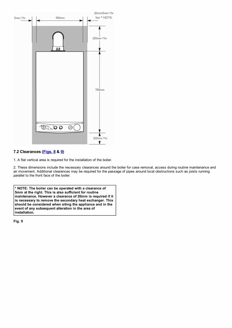
7.2 Clearances (Figs. 8 & 9)
1. A flat vertical area is required for the installation of the boiler.
2. These dimensions include the necessary clearances around the boiler for case removal, access during routine maintenance andair movement. Additional clearances may be required for the passage of pipes around local obstructions such as joists runningparallel to the front face of the boiler.
* NOTE: The boiler can be operated with a clearance of5mm at the right. This is also sufficient for routinemaintenance. However a clearance of 20mm is required if itis necessary to remove the secondary heat exchanger. Thisshould be considered when siting the appliance and in theevent of any subsequent alteration in the area ofinstallation.
Fig. 9

page 14
7.3 Ventilation of Compartments
1. Where the appliance is installed in a cupboard or compartment, no air vents are required.
2. BS 5440: Part 2 Clause 4.2 refers to room sealed appliances installed in compartments. The appliance will run sufficiently coolwithout ventilation.
7.4 Gas Supply
1. The gas installation should be in accordance with the relevant standards. In GB this is BS 6891. In IE this is the current edition ofI.S. 813 "Domestic Gas Installations".
2. The connection to the appliance is a 22mm copper tail located at the rear of the gas service cock (Fig. 10).
3. Ensure that the pipework from the meter to the appliance is of adequate size. Do not use pipes of a smaller diameter than theboiler gas connection (22mm).
Fig. 10
7.5 Electrical Supply
1. External wiring must be correctly earthed, polarised and in accordance with relevant regulations/rules. In GB this is the currentI.E.e. Wiring Regulations. In IE reference should be made to the current edition of ETCI rules.

2. The mains supply is 230V ~ 50Hz fused at 3A.
NOTE: The method of connection to the electricity supplymust facilitate complete electrical isolation of the appliance.
Connection may be via a fused doublepole isolator with acontact separation of at least 3mm in all poles andservicing the boiler and system controls only.
page 15
7.6 Condensate Drain
FAILURE TO INSTALL THE CONDENSATE DISCHARGEPIPEWORK CORRECTLY WILL AFFECT THE RELIABLEOPERATION OF THE BOILER
The condensate discharge pipe MUST NOT RISE at anypoint along its length. There MUST be a fall of AT LEAST2.5° (50mm per metre) along the entire run.
1. The condensate outlet terminates in a 1" BSP nut and seal for the connection of 21.5mm (3/4in) plastic overflow pipe whichshould generally discharge internally into the household drainage system. If this is not possible, discharge into an outside drain isacceptable.
2. Ensure the discharge of condensate complies with any national or local regulations in force. BS 6798:2000 & Part H1 of the Building Regulations give further guidance.
3. The discharge pipe should be run in a proprietary drain pipe material e.g. PVC, PVCU, ABS, PVCC or PP.
4. Metal pipework is NOT suitable for use in condensate discharge systems.
5. The pipe should be a minimum of 21.5mm diameter and must be supported using suitably spaced clips to prevent sagging.
6. It is advisable to keep the condensate pipe internal.
7. External runs greater than 3 metres or runs in cold areas should use 32mm waste pipe.
8. If the boiler is fitted in an unheated location the entire condensate discharge pipe should be treated as an external run.
9. In all cases discharge pipe must be installed to aid disposal of the condensate. To reduce the risk of condensate being trapped,as few bends and fittings as possible should be used.
10. When discharging condensate into a soil stack or waste pipe the effects of existing plumbing must be considered. If soil pipes orwaste pipes are subjected to internal pressure fluctuations when WC's are flushed or sinks emptied then backpressure may forcewater out of the boiler trap and cause appliance lockout.
Examples are shown of the following methods of termination: i) to an internal soil & vent pipe ii) via an internal discharge branch (e.g. sink waste) iii) to a drain or gully iv) to a purpose made soakaway

page 16
7.7 Flue

NOTE: Due to the nature of the boiler a plume of water vapourwill be discharged from the flue. This should be taken intoaccount when siting the flue terminal.
1. The following guidelines indicate the general requirements for siting balanced flue terminals. For GB recommendations are givenin BS 5440 Pt 1. For IE recommendations are given in the current edition of I.S. 813 "Domestic Gas Installations".
2. If the terminal discharges onto a pathway or passageway, check that combustion products will not cause a nuisance and that theterminal will not obstruct the passageway.
3. If a terminal is less than 2 metres above a balcony, above ground or above a flat roof to which people have access, then asuitable terminal guard must be provided.
IMPORTANT:
• Only ONE 25mm clearance is allowed per installation. • Under car ports we recommend the use of the plumedisplacement kit. • The terminal position must ensure the safe and nuisance freedispersal of combustion products.
Terminal Position with Minimum Distance (Fig.
11)(mm)
Aa Directly below an opening, air brick,opening windows, etc.
300
Ba Above an opening, air brick, openingwindow etc.
300
Ca Horizontally to an opening, air brick,opening window etc.
300
D Below gutters, soil pipes or drain pipes. 25
E Below eaves. 25
F Below balconies or car port roof. 25
G From a vertical drain pipe or soil pipe. 25
H From an internal or external corner. 25
I Above ground, roof or balcony level. 300
J From a surface or boundary line facing aterminal.
600
K From a terminal facing a terminal(Horizontal flue). From a terminal facing a terminal(Vertical flue)
1200 600
L From an opening in carport (e.g. door,window) into the dwelling.
1200
M Vertically from a terminal on the samewall.
1500
N Horizontally from a terminal on the samewall.
300
R From adjacent wall to flue (vertical only). 300
S From an adjacent opening window(vertical only).
1000
T Adjacent to windows or openings onpitched and flat roofs
600
U Below windows or openings on pitchedroofs
2000
a In addition, the terminal should be no nearer than 150 mm to an opening in the building fabric formed for the purpose ofaccommodating a builtin element such as a window frame. See BS 5440 Pt. 1.
Fig. 11

NOTE: The distance from a fanned draught appliance terminal installed parallel to a boundary may not be less than 300mm inaccordance with the diagram below
Fig. 12
IMPORTANT: If fitting a Plume Displacement Flue Kit, the airinlet must be a minimum of 100mm from any opening windowsor doors (see Section 9.0).
Fig. 12a

page 17
8.0 Flue Options
8.1 Horizontal Flue Systems
1. The standard flue is suitable only for horizontal termination applications.
2. All fittings should be fully engaged. The approximate engagement is 40mm. Apply soap solution to the seal on each fitting to aidassembly.
3. Maximum permissible equivalent flue lengths are:
Horizontal Concentric 4 metres
4. Any additional "in line" bends in the flue system must be taken into consideration. Their equivalent lengths are: Concentric Pipes:
135° bend 0.5 metres93° bend 1.0 metres
The elbow supplied with the standard horizontal telescopic flue kit is not included in any equivalent length calculations
NOTE: Flue length is measured from point X to Y as shown.
IMPORTANT: All flue systems must be securely supportedat least once every metre. Suitable pipe supports areavailable as accessories.
Plume Displacement Kit 60 /100 Ø
1M Extensions, 45° & 93° bends are also available see Section 9.0
NOTE: Horizontal flue pipes should always be installed with a 1.5° fall from the terminal to allow condensate to run back to theboiler.

page 18
8.2 Vertical Flue Systems
1. Maximum permissible equivalent flue lengths are:
Vertical Concentric 4m
2. Any additional "in line" bends in the flue system must be taken into consideration. Their equivalent lengths are:Concentric Pipes:
45° bend 0.5 metres93° bend 1.0 metres
The elbow supplied with the standard horizontal flue is not included in any equivalent length calculations
NOTE: Flue length is measuredfrom point X to Y as shown.
IMPORTANT: All flue systems mustbe securely supported at least onceevery metre. Suitable pipesupports are available asaccessories.
Total Equivalent Length = A+B+C+1x90°Bend
All vertical and angled runs must be included, measured from the boiler adaptor (point X) to the joint with the flue terminal (point Y).One 91.5° bend or two 135° bends can be included without reduction of the flue length.
If further elbows are required the flue length must be reduced by the following amounts:
1 metre for each 91.5° bend 0.5 metre for each 135° bend
page 19
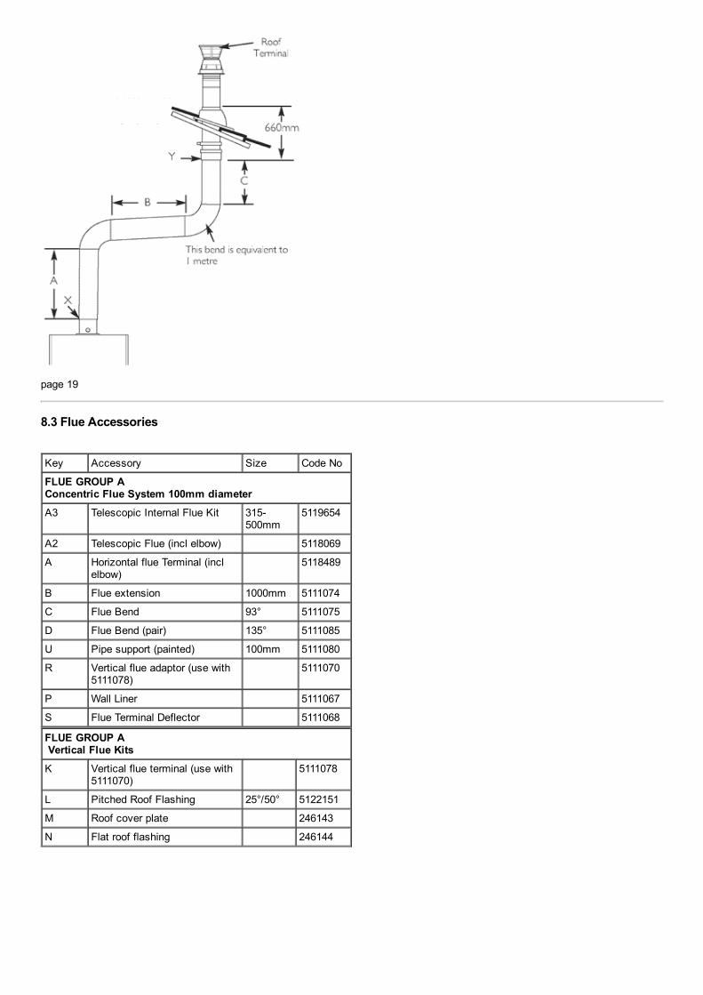
8.3 Flue Accessories
Key Accessory Size Code No
FLUE GROUP AConcentric Flue System 100mm diameterA3 Telescopic Internal Flue Kit 315
500mm5119654
A2 Telescopic Flue (incl elbow) 5118069
A Horizontal flue Terminal (inclelbow)
5118489
B Flue extension 1000mm 5111074
C Flue Bend 93° 5111075
D Flue Bend (pair) 135° 5111085
U Pipe support (painted) 100mm 5111080
R Vertical flue adaptor (use with5111078)
5111070
P Wall Liner 5111067
S Flue Terminal Deflector 5111068
FLUE GROUP A Vertical Flue KitsK Vertical flue terminal (use with
5111070) 5111078
L Pitched Roof Flashing 25°/50° 5122151
M Roof cover plate 246143
N Flat roof flashing 246144

page 20
8.6 For Roof Terminals
1. In the case of a pitched roof 25 50 degrees, position the lead tile to replace/flash over existing roof tiling. Make an aperture inthe roof suitable for the lower tube of the roof terminal and ensure the integrity of the roof cover is maintained. The adjustable plasticcollar can either be positioned on the lead tile or the lower tube of the roof terminal prior to the final positioning of the vertical fluethrough the tile. Check the collar is correctly located to suit required roof pitch (either 25° to 38° or 37° to 50°). From inside the roofadjust the flue to a vertical position and secure to the roof structure with the clamp supplied.
2. For flat roof installations the aluminium flashing must be incorporated into the roof covering and the appropriate aperture made inthe roof decking. The vertical flue is lowered onto the flashing making sure the collar of the flue locates securely with the flashing.(A mastic seal may be necessary). From inside the roof, adjust the flue to a vertical position and secure to the roof structure withthe clamp supplied.
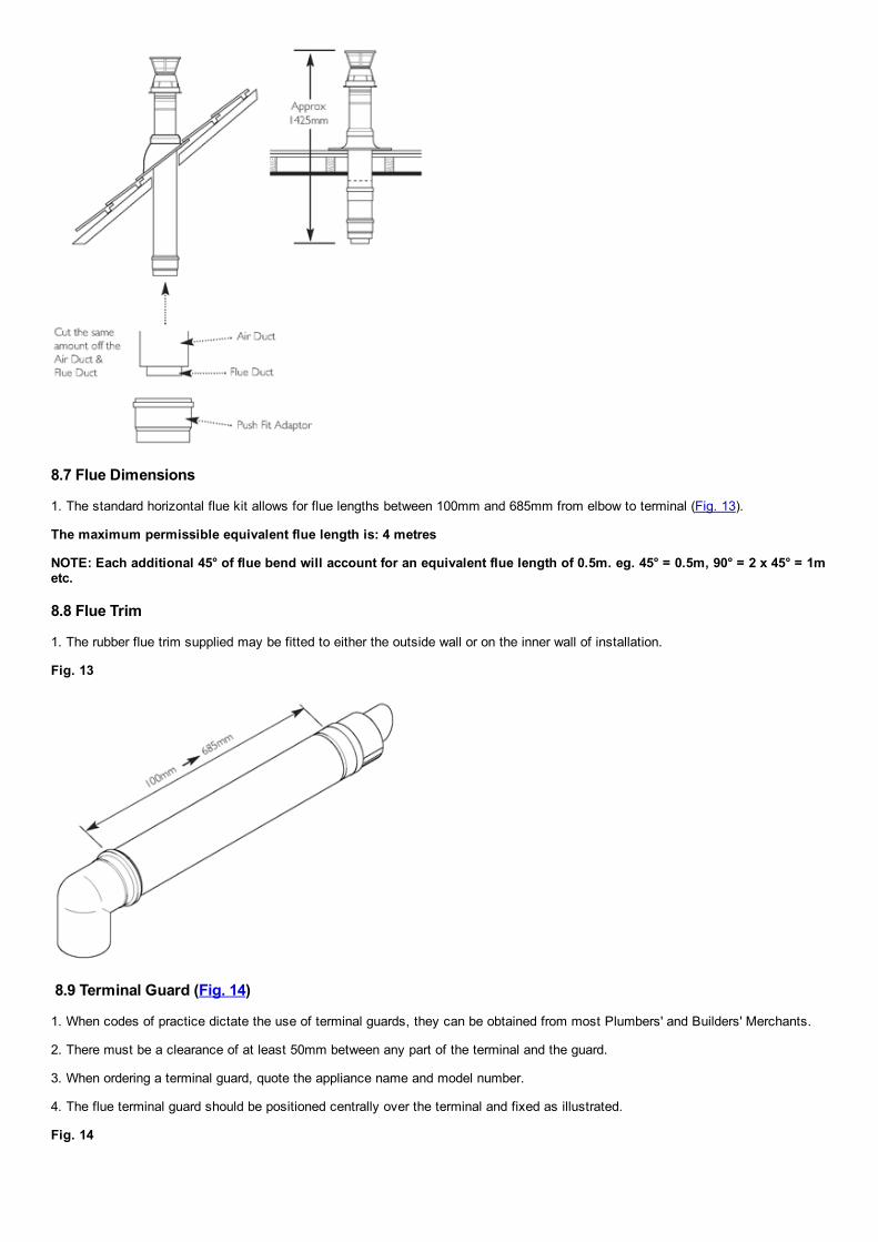
8.7 Flue Dimensions
1. The standard horizontal flue kit allows for flue lengths between 100mm and 685mm from elbow to terminal (Fig. 13).
The maximum permissible equivalent flue length is: 4 metres
NOTE: Each additional 45° of flue bend will account for an equivalent flue length of 0.5m. eg. 45° = 0.5m, 90° = 2 x 45° = 1metc.
8.8 Flue Trim
1. The rubber flue trim supplied may be fitted to either the outside wall or on the inner wall of installation.
Fig. 13
8.9 Terminal Guard (Fig. 14)
1. When codes of practice dictate the use of terminal guards, they can be obtained from most Plumbers' and Builders' Merchants.
2. There must be a clearance of at least 50mm between any part of the terminal and the guard.
3. When ordering a terminal guard, quote the appliance name and model number.
4. The flue terminal guard should be positioned centrally over the terminal and fixed as illustrated.
Fig. 14

8.10 Flue Deflector (Fig. 13a)
1. If required a flue deflector is available from your Potterton stockist.
2. Push the flue deflector over the terminal end and rotate to the optimum angle for deflecting plume. Secure the deflector to theterminal with screws provided.
Fig. 13a
page 21
9.0 Plume Displacement
9.1 Plume Displacement Kit (Fig. 14b)
Kit No5118638 Content ofkit
1 0.9m 60/100 ConcentricFlue
1 1m 60 Dia Exhaust FluePipe
1 Adaptor2 60 Dia Support Brackets1 93° Elbow/Plume Outlet
Assembly1 Flexible Flue Trim3 "O" Rings1 'Jubilee Clip1 Boiler Elbow

1. This kit is recommended for installations where the condensate plume emitted from the flue may cause a nuisance or affect thesurroundings.
2. The terminal must be positioned outside the building with the air inlet facing downward and outlet connection upwards.
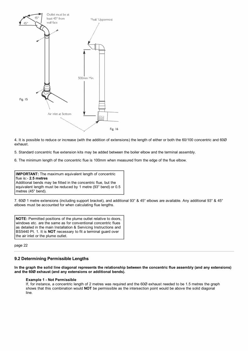
3. The plume outlet must always be at least 45° to the wall, with the 'peak' uppermost to prevent rain entry (Figs. 15 & 16), and be atleast 2 metres above ground level. It must be secured as shown in Fig. 12a. The plume outlet must also be at least 500mm from theair inlet in any direction (Fig. 16).
NOTE: The outlet must be positioned so that any condensateplume is directed away from adjacent surfaces. There must be aconstant fall along the entire length of the flue system from theoutlet back to the boiler.
4. It is possible to reduce or increase (with the addition of extensions) the length of either or both the 60/100 concentric and 60Øexhaust.
5. Standard concentric flue extension kits may be added between the boiler elbow and the terminal assembly.
6. The minimum length of the concentric flue is 100mm when measured from the edge of the flue elbow.
IMPORTANT: The maximum equivalent length of concentricflue is: 2.5 metres Additional bends may be fitted in the concentric flue, but theequivalent length must be reduced by 1 metre (93° bend) or 0.5metres (45° bend).
7. 60Ø 1 metre extensions (including support bracket), and additional 93° & 45° elbows are available. Any additional 93° & 45°elbows must be accounted for when calculating flue lengths.
NOTE: Permitted positions of the plume outlet relative to doors,windows etc. are the same as for conventional concentric fluesas detailed in the main Installation & Servicing Instructions andBS5440 Pt. 1. It is NOT necessary to fit a terminal guard overthe air inlet or the plume outlet.
page 22
9.2 Determining Permissible Lengths
In the graph the solid line diagonal represents the relationship between the concentric flue assembly (and any extensions)and the 60Ø exhaust (and any extensions or additional bends).
Example 1 Not Permissible If, for instance, a concentric length of 2 metres was required and the 60Ø exhaust needed to be 1.5 metres the graphshows that this combination would NOT be permissible as the intersection point would be above the solid diagonalline.

Example 1 Flue Lengths Not Permissible
Example 2 Flue Lengths OK Where both lengths have been determined they can be applied to the graph to check that the installation ispermissible. For example, if it was known that 1 metre of concentric flue and 1.5 metres of 60Ø exhaust were required,the values could be applied to the graph as shown in Example 2. As the point of intersection of the dotted lines isbelow the solid diagonal line, the combination of lengths is shown to be acceptable.
Example 2 Flue Lengths OK
Example 3 Flue Lengths OK In the example shown, assume that the concentric part of the flue needs to be 1 metres long. Find the position of '1'on the horizontal axis of the graph and then project upwards to the solid diagonal line. This is represented by thevertical thick dotted line. Where this dotted line intersects with the solid diagonal line on the graph, project across tothe vertical axis. As can be seen this corresponds with 2 metres. Therefore, the total equivalent length of the 60Øexhaust can be up to 2 metres. Any bend equivalencies must be accounted for i.e. 93° bends are equal to 1 metre,each 45° bend to 0.5 metres.
Example 3 Flue Lengths OK
Flue Length Worked Example Potterton Performa 24 Eco HE2

In Fig. 18 opposite an additional 93° bend has been included inthe 60Ø exhaust. with 2 x 1metre extensions which have beencut to 0.25metres and fitted. The waste is discarded.
To calculate total length:
2 x 0.25 metre Lengths = 0.5 metres 1 x 93° Elbow = 1 metre
Total 60Ø Exhaust = 1.5 metres
After consulting the table in Example 3 it can be determined thatthe concentric flue could be up to approximately 0.5 metreslong.
Fig. 17 & Fig. 18AdditionalAccessories
A 93° Elbow B 45° Elbow(Pair) C 1 metre60ØOslash;Extension
5117381 51173825117380
page 23
9.3 General Fitting Notes
1. Cut a hole in the external wall which the concentric flue assembly will pass through. The hole should allow the flue to fall back tothe boiler at an angle of at least 1.5°.
2. When completed the terminal must be at least 2 metres above ground level (Fig. 19).
Fig. 19
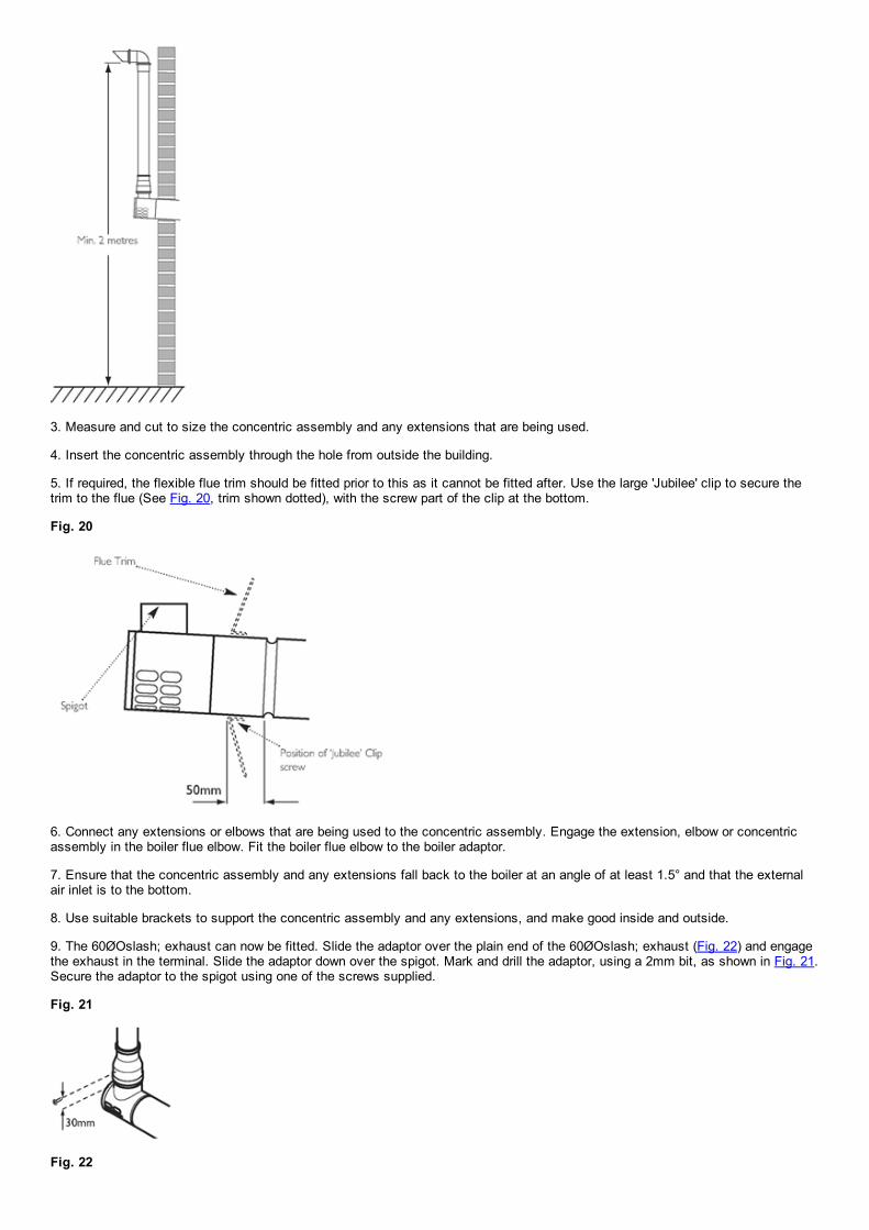
3. Measure and cut to size the concentric assembly and any extensions that are being used.
4. Insert the concentric assembly through the hole from outside the building.
5. If required, the flexible flue trim should be fitted prior to this as it cannot be fitted after. Use the large 'Jubilee' clip to secure thetrim to the flue (See Fig. 20, trim shown dotted), with the screw part of the clip at the bottom.
Fig. 20
6. Connect any extensions or elbows that are being used to the concentric assembly. Engage the extension, elbow or concentricassembly in the boiler flue elbow. Fit the boiler flue elbow to the boiler adaptor.
7. Ensure that the concentric assembly and any extensions fall back to the boiler at an angle of at least 1.5° and that the externalair inlet is to the bottom.
8. Use suitable brackets to support the concentric assembly and any extensions, and make good inside and outside.
9. The 60ØOslash; exhaust can now be fitted. Slide the adaptor over the plain end of the 60ØOslash; exhaust (Fig. 22) and engagethe exhaust in the terminal. Slide the adaptor down over the spigot. Mark and drill the adaptor, using a 2mm bit, as shown in Fig. 21.Secure the adaptor to the spigot using one of the screws supplied.
Fig. 21
Fig. 22

10. If it is necessary to shorten the 60ØOslash; exhaust or any of the extensions, the excess material must be cut from the plainend of the pipe.
11. Determine the position of the 60ØOslash; exhaust and mark on the wall a suitable position for the support bracket. If extensionsare being used, a support bracket is supplied in each kit.
12. Drill the wall, and fit the bracket(s) using the plug and screw provided.
13. Mark and drill the 60ØOslash; exhaust, using a 2mm bit, as shown in Fig. 23. Complete the installation of the 60ØOslash;exhaust, securing in the brackets.
Fig. 23
Fig. 24
14. Fit the 93° elbow/plume outlet and secure with the two remaining screws supplied. Ensure the plume outlet is at least 45° to thewall and that the 'peak' is uppermost (Fig. 24).
page 24
15. For aesthetic purposes it is permissible to route the 60ØOslash; exhaust in an enclosed box, but the air inlet and plume outletMUST remain in free air.
16. It is also possible to separate the plume outlet from the 93° elbow to allow the flue to be installed as shown in Fig. 25.
Fig. 25
17. To do this, first slacken the two screws retaining the plume outlet to the elbow, and remove the outlet (Fig. 26). The elbow cannow be used to connect the vertical to horizontal 60ØOslash; exhaust (Fig. 25). Retighten the screws in the elbow.
Fig. 26

18. The outlet can now be fitted into the female end of an 60ØOslash; extension piece. It must be secured using two of the screwssupplied in the bag with the 'Jubilee' clip.
19. Mark the female end of the extension at 30mm as shown in two positions, directly opposite each other (Fig. 27).
Fig. 27
20. Using a suitable bit (e.g. 2mm), drill through the extension and outlet. Secure using two of the screws supplied.
21. The remaining screw must be used to secure the adaptor to the concentric terminal.
22. When the plume outlet is positioned under a balcony or other projection (Fig. 28) it must protrude at least 200mm (it is notnecessary to extend it further than this).
Fig. 28
23. When under balconies or projections it is permissible to rotate the concentric flue length up to 70°, clockwise or anticlockwise(Fig. 29), if there is insufficient space to connect vertically.
24. This will allow the connection of the exhaust to the outlet spigot.
25. All other minimum & maximum dimensions must be adhered to, and the air inlet positioned such that it will not be subject to rainentry.
Fig. 29
page 25

10.0 Installation
10.1 Initial Preparation
The gas supply, gas type and pressure must be checked for suitability before connection (see Section 7.4).
1. After considering the site requirements (see Section 7.0) position the fixing template on the wall ensuring it is level bothhorizontally and vertically.
2. Mark the position of the two most suitable fixing slots for the wall plate and boiler lower fixing holes. It is preferable to use thehorizontal fixing slots.
3. Mark the position of the centre of the flue hole (rear exit). For side flue exit, mark as shown (Fig. 30).
Fig. 30
4. Note the shaded area on the template. Pipework may be routed upwards behind the boiler, providing it does not conflict with theshaded area.
5. If required, mark the position of the gas and water pipes. Remove the template.
6. Cut the hole for the flue (minimum diameter 116mm).
7. Drill the wall as previously marked to accept the wall plugs supplied. Secure the wall plate using the fixing screws.
8. Using a spirit level ensure that the plate is level before finally tightening the screws.
9. Connect the gas and water pipes to the valves on the wall plate using the copper tails supplied. Ensure that the sealing washersare fitted between the connections.
10.2 Flushing
1. Connect a tube to the central heating flow or return pipe (Fig. 31).
2. Flush thoroughly (see System Details, Section 6.2).
Fig. 31
10.3 Preparing The Boiler
1. Remove all packaging.
2. Stand the boiler on its base by using the rear lower edge as a pivot.
NOTE: A small amount of watermay drain from the boiler in the

upright position.
page 26
10.4 Fitting The Boiler
1. Remove the sealing caps from the boiler connections.
NOTE: A small amount of water maydrain from the boiler once the capsare removed.
2. Lift the boiler as indicated by the shaded areas. The boiler should be lifted by TWO PEOPLE. Engage the slots at the top rear ofthe boiler on the wall plate (Fig. 32) (see Safe Manual Handling).
Fig. 32
3. Ensure that the boiler is level and sits against the wall.
4. Remove the elbows, valves and sealing washers from the packaging. The 3/4 in valve with internal filter must be fitted to thecentral heating return.
5. Using the sealing washers provided connect the valves to the heating flow and return, and the cold water mains inlet.
6. Connect the elbows to the gas service cock and hot water outlet pipe, and then connect the elbows to the boiler. Connect theelbows with flared ends to the valves.
7. Ensure that the sealing washers are used on all connections. The rubber washers must be used on the gas connections.
8. The gas and water supplies, central heating flow and return and domestic hot water can now be connected.
9. Tighten all the connections and fit the filling loop (if using the accessory).
Fig. 32a

10.5 Fitting the Safety Pressure Relief Discharge Pipe (Fig. 33)
1. Remove the discharge pipe from the kit.
2. Determine the routing of the discharge pipe in the vicinity of the boiler. Make up as much of the pipework as is practical, includingthe discharge pipe supplied.
3. The pipework must be at least 15mm diameter and run continuously downwards to a discharge point outside the building. Seesection 6.7 for further details.
4. Utilising one of the sealing washers, connect the discharge pipe to the adaptor and carefully tighten the nut.
5. Complete the discharge pipework and route it to the outside discharge point.
Fig. 33
10.6 Condensate Drain (see section 7.6)
1. Connect the condensate drain using the 1" BSP nut and seal supplied.
Ensure the discharge of condensate complies withany national or local regulations in force (seeBritish Gas "Guidance Notes for the Installation ofDomestic Gas Condensing Boilers".
2. The condensate outlet terminates in a 1" BSP nut and seal for the connection of 21.5mm (3/4in) plastic overflow pipe whichshould generally discharge internally into the household drainage system. If this is not possible, discharge into an outside drain isacceptable.
page 27

10.7 Fitting The Flue
HORIZONTAL FLUE
1. The standard flue is suitable for lengths between 100mm minimum and 685mm maximum, as measured from the edge of the flueelbow outlet to the joint between the terminal and air duct (Fig. 34).
Fig. 34
2. Locate the flue elbow on the adaptor at the top of the boiler. Set the elbow to the required orientation (Fig. 35).
Fig. 35
NOTE: The flue elbow is angled at 91.5 degreesto ensure a fall back to the boiler.
3. Measure the distance from the outside wall face to the elbow. This dimension will be known as 'X' (Fig. 36).
4. To dimension 'X' add 50mm. This dimension to be known as 'Y'.
IMPORTANT: Check all dimensions beforecutting.
Fig. 36

page 28
5. Mark dimension 'Y' on the flue as shown (Fig. 37). Carefully cut the waste material from the flue, ensuring that the ducts aresquare and free from burrs.
Fig. 37
6. The inner flue duct support bracket may be in the waste portion of the flue. In this case retrieve the bracket before discarding thewaste.
7. Take the inner flue support bracket (if not already fitted) and engage it over the flue duct. This will centralise the flue and airducts, and ease assembly (Fig. 38).
Fig. 38

8. Insert the flue through the hole in the wall. Fit the elbow to the boiler adaptor, ensuring that it is pushed fully in.
9. Draw the flue back through the wall and engage it in the elbow. It may be necessary to use soap solution or similar to easeassembly of the elbow adaptor and flue (Fig. 39).
Fig. 39
10. Make good between the wall and air duct outside the building.
11. Fit the flue trim if required, and if necessary fit a terminal guard (see Section 8.8 & 8.9).
VERTICAL FLUE
1. Only a flue approved with the Potterton Performa 24 Eco HE2 can be used.
page 29
10.8 Making The Electrical Connections
To connect the mains input cable proceed as follows:
1. Slacken the facia securing screws and lift the outercase panel so that its locating tabs are clear of the facia. Remove the panel.
2. Completely undo the screws securing the facia panel and hinge it down (Fig. 40).

Fig. 43
3. Remove the control box cover securing screws. Disengage the barbs on the control box from the cover. Remove the cover (Fig.41).
4. Slacken the cable clamp on the LH side of the boiler chassis (Fig. 42). Insert the cable through the clamp and route it to theterminal block.
5. Slacken the screws in the terminal block, connect the input cable, and tighten the screws.
6. If an external control is to be connected it can be done at this point. Run the input cable from the external control through thesecond cable clamp on the boiler chassis. Refer to the instructions supplied with the control.
7. To connect external control(s) remove the link between terminals 1 & 2. The 230V supply at terminal 1 must be connected to theexternal control. The switched output from the external control must be connected to terminal 2 (Fig. 43).
NOTE: If the room thermostatbeing used incorporates ananticipator it MUST be wired asshown in Fig. 43
IMPORTANT: The external controlMUST be suitable for 230Vswitching.
8. Ensure that both mains input and, where fitted, external control input cables have sufficient slack to allow the control box to dropdown. Tighten the cable clamp(s) on the boiler chassis.
9. If the optional integral timer is to be used it should be fitted at this point. Refer to the instructions supplied with the timer. NOTE:An external frost thermostat cannot be used with the integral timer.

10.9 Preliminary Electrical Checks
1. Prior to commissioning the boiler preliminary electrical system checks should be carried out.
2. These should be performed using a suitable meter, and include checks for Ground Continuity, Resistance to Ground, Short Circuitand Polarity.
Fig. 44
page 30
11.0 Commissioning the Boiler
11.1 Commissioning the Boiler
1. Reference should be made to BS 5449 Section 5 when commissioning the boiler.
2. At the time of commissioning complete all relevant sections of the Benchmark Commissioning Checklist at the rear of thispublication.
3. Open the mains water supply to the boiler.
4. Open all hot water taps to purge the DHW system.
5. Ensure that the filling loop is connected and open, then open the heating flow and return valves on the boiler.
6. Open the cap on the automatic air vent (Fig. 45).
7. The system must be flushed in accordance with BS 7593 (see Section 6.2) and the flushing agent manufacturers instructions.
8. Pressurise the system to 1.0 bar then close and disconnect the filling loop.
9. Turn the gas supply on and purge according to in GB BS 6891 and in IE I.S. 813 "Domestic Gas Installations".
10. Test for gas soundness.
11. If at any time during commissioning it is required to terminate a particular cycle, e.g. the pump overrun period, turn the selectorto the OFF position and then back to either ( ) or ( ) (Fig. 47).
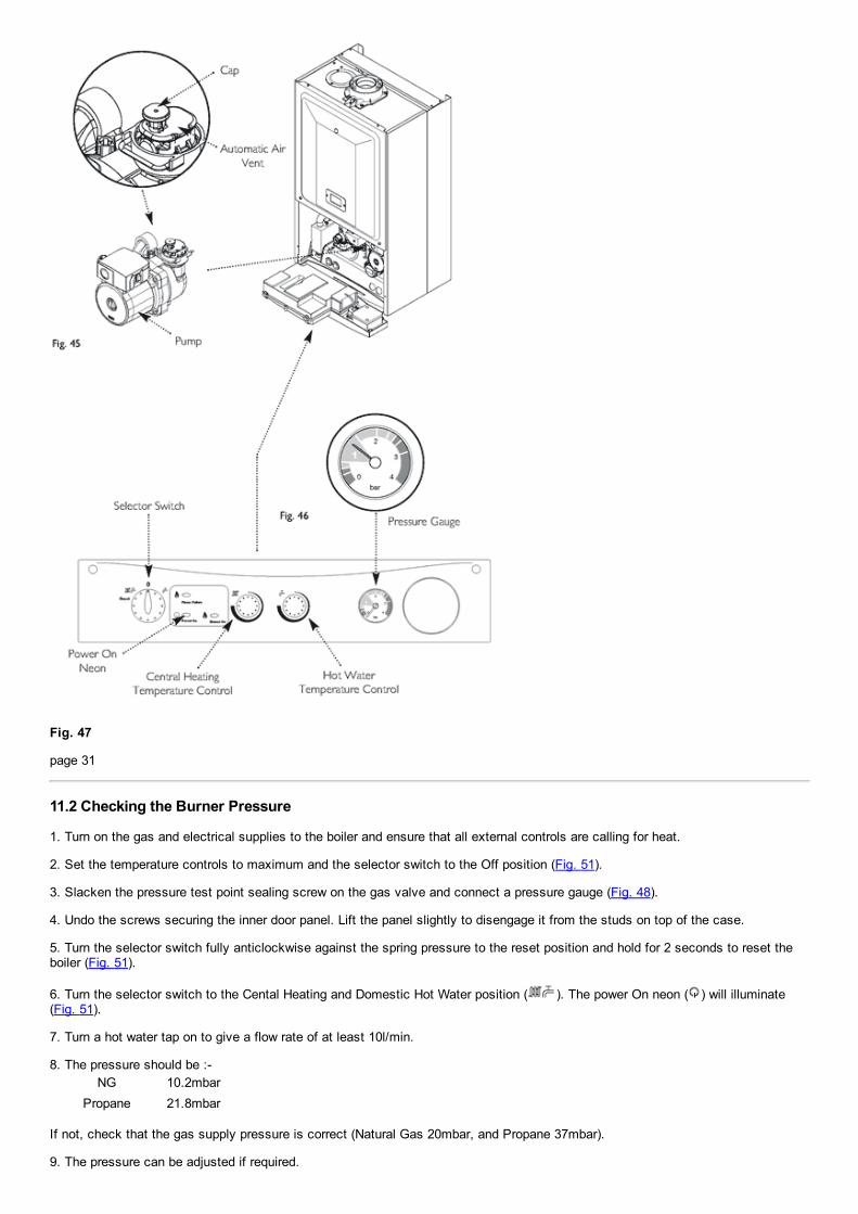
Fig. 47
page 31
11.2 Checking the Burner Pressure
1. Turn on the gas and electrical supplies to the boiler and ensure that all external controls are calling for heat.
2. Set the temperature controls to maximum and the selector switch to the Off position (Fig. 51).
3. Slacken the pressure test point sealing screw on the gas valve and connect a pressure gauge (Fig. 48).
4. Undo the screws securing the inner door panel. Lift the panel slightly to disengage it from the studs on top of the case.
5. Turn the selector switch fully anticlockwise against the spring pressure to the reset position and hold for 2 seconds to reset theboiler (Fig. 51).
6. Turn the selector switch to the Cental Heating and Domestic Hot Water position ( ). The power On neon ( ) will illuminate(Fig. 51).
7. Turn a hot water tap on to give a flow rate of at least 10l/min.
8. The pressure should be :NG 10.2mbar
Propane 21.8mbar
If not, check that the gas supply pressure is correct (Natural Gas 20mbar, and Propane 37mbar).
9. The pressure can be adjusted if required.

10. To check and set minimum pressure first remove one of the modulator wires.
Adjusting the Pressure (Fig 49)
11. Remove the plastic protection cap from the pressure adjustment nuts on the valve.
12. The smaller nut (5mm) adjusts minimum pressure and the larger nut (8mm) maximum pressure.
13. Using a suitable spanner adjust the relevant nut until the correct pressure is achieved.
14. Once the pressure has been set turn the boiler off and disconnect the pressure gauge.
15. Tighten the pressure test screw and refit the modulator to the valve. Reassemble in reverse order.

Fig. 51
page 32
12.0 Completion
12.1 Completion
1. Refit the case front panel and tighten the securing screws (Fig. 52).
2. Instruct the user in the operation of the boiler and system, explaining the operational sequence.

3. Carefully read and complete all sections of the Benchmark Commissioning Checklist at the rear of this publication that arerelevant to the appliance and installation. These details will be required in the event of any warranty work. The publication must behanded to the user for safe keeping and each subsequent regular service visit recorded.
4. For IE, it is necessary to complete a "Declaration of Conformity" to indicate compliance with I.S. 813. An example of this is givenin I.S. 813 "Domestic Gas Installations". This is in addition to the Benchmark Commissioning Checklist.
5. Hand over the Users Operating, Installation and Servicing Instructions, giving advice on the necessity of regular servicing.
Fig. 52
page 33
13.0 Servicing the Boiler
13.1 Annual Servicing
1. For reasons of safety and economy, it is recommended that the boiler is serviced annually. Servicing must be performed by acompetent person.
2. After servicing, complete the relevant Service Interval Record section of the Benchmark Commissioning Checklist at the rear ofthis publication.
3. Ensure that the boiler is cool.
4. Ensure that both the gas and electrical supplies to the boiler are isolated.
5. Slacken the screws securing the facia panel. Lift the outercase panel so that its securing tabs are clear of the facia. Remove thepanel (Fig. 53).
Fig. 53

6. Remove the screws securing the inner door panel. Lift the panel slightly to disengage it from the studs on top of the case (Fig.54).
7. Note the positions of the three wires on the fan motor and remove them. Remove the sensing tube from the fan spigot (Fig. 55).
8. Slacken the screws on the fan spigot outlet pipe clamp. Ease the clamp to the left over the pipe.
9. Remove the four screws securing the combustion box door and remove the door (Fig. 54).

page 34
11. Ease the front edge of the left hand air baffle upwards, disengaging the spring clip. Disengage the tab on the baffle from the slotin the fan hood (Fig. 56).
12. Undo the screws securing the fan and hood to the appliance back panel. Draw the assembly forwards (Fig. 57).
13. Undo the screws securing the burner to the injector manifold. Draw the burner out of the combustion box, pulling the electrodegrommets from the slots in the combustion box lower panel (Fig. 58).
14. Disconnect the electrode leads and grommets from the electrodes. Completely remove the burner (Fig. 58).
15. Brush any deposits from the injectors. Do not use a pin or wire to clean them.
16. Brush the burner blades and venturis and clean the combustion box.
17. Ensure that the heat exchanger fins are clear of any obstruction.
NOTE: If necessary the secondaryheat exchanger may be dismantled see section 14.24.
DHW Filters (Fig. 60)

18. If the flow of domestic hot water is diminished, it may be necessary to clean the filters.
19. Initially check the cold water inlet tap filter.
20. Turn the tap off and undo the blanking cap (Fig. 59).
21. Extract the filter and rinse thoroughly in clean water. Reassemble and check the flow. If required clean the manifold filter asdescribed below.
22. Undo the filter cartridge from the inlet/return manifold.
23. Dismantle the cartridge and carefully remove the flow regulator and filter gauze. Rinse them thoroughly in clean water andreassemble in reverse order.
24. Check that the pressure vessel charge is 0.5bar and reassemble in reverse order of dismantling and recommission.
25. Turn the selector switch fully anticlockwise against the spring pressure to the reset position and hold for 2 seconds to reset theboiler.
26. Complete the relevant Service Interval Record section of the Benchmark Commissioning Checklist at the rear of this publicationand then hand it back to the user.
page 35
14.0 Changing Components IMPORTANT: When changing componentsensure that both the gas and electrical suppliesto the boiler are isolated before any work isstarted. When the new component has beenfitted turn the selector switch fullyanticlockwise against the spring pressure tothe 'Reset' position and hold for 2 seconds toreset the boiler before recommissioning.
See Section 13.1 "Annual Servicing" for removal of case panel, door etc.
14.1 Fan (Figs. 62 & 63)
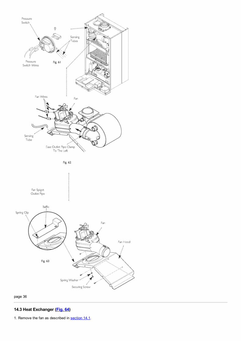
1. Note the positions of the sensing tube on the outlet elbow and three wires on the fan motor and remove them.
2. Slacken the screw on the fan spigot outlet pipe clamp. Ease the clamp to the left over the pipe.
3. Remove the four screws securing the combustion box door and remove the door.
4. Ease the front edge of the left hand baffle upwards, disengaging the spring clip. Disengage the tab on the baffle from the slot inthe fan hood.

5. Undo the screws securing the fan hood to the appliance back panel, and draw the fan and hood assembly forwards.
6. Remove the screws and spring washers securing the fan to the hood, and the screw securing the outlet pipe.
7. Transfer the outlet pipe and clamp to the new fan.
8. Fit the new fan to the hood using the screws and spring washers previously removed.
9. Reassemble in reverse order of dismantling.
14.2 Pressure Switch (Fig. 61)
1. Remove the fan and hood assembly as described in section 14.1.
2. Note the positions of the two sensing tubes and wires and remove them.
3. Remove the screw holding the pressure switch bracket on the combustion box top panel.
4. Unclip the switch from the bracket. Transfer the bracket to the new switch.
5. Fit the new pressure switch and reassemble all components in reverse order of dismantling.
page 36
14.3 Heat Exchanger (Fig. 64)
1. Remove the fan as described in section 14.1.

2. Drain the primary circuit. Prise the three pipe connecting clips off the joints in the flow and return pipes. Remove the heatexchanger return pipe.
3. Lift the heat exchanger to disconnect the flow pipe joint. Withdraw it from the appliance, taking care not to damage the rearinsulation piece.
4. Fit the new heat exchanger.
5. Reassemble in reverse order of dismantling, and repressurise the system.
Fig. 64
14.4 Burner (Fig. 65)
1. Remove the four screws securing the combustion box door and remove the door.
2. Undo the screws securing the burner to the injector manifold. Draw the burner out of the combustion box, pulling the electrodegrommets from the slots in the combustion box lower panel.
3. Disconnect the electrode leads and grommets from the electrodes. Completely remove the burner.
4. Undo the screws securing the electrodes to the burner. Examine the condition of the electrodes, replacing if necessary. Fit theelectrodes to the new burner.
5. Engage the burner location brackets over the studs on the injector manifold and reassemble in reverse order.
Fig. 65

page 37
14.5 Injectors (Fig. 66)
1. Remove the burner as described in Section 14.4.
2. Undo the screws securing the injector manifold to the inlet elbow and remove the manifold.
3. Unscrew and replace injectors as required and examine the sealing gasket, replacing as necessary. Reassemble in reverse order.
14.6 Electrodes (Fig. 66)
1. Remove the four screws securing the combustion box door and remove the door.
2. Undo the screws securing the burner to the injector manifold. Draw the burner out of the combustion box, pulling the electrodegrommets from the slots in the combustion box lower panel.
3. Disconnect the lead and grommet from the electrode being replaced. Undo the securing screw and withdraw the electrode to theburner.
4. Reassemble in reverse order.
14.7 Insulation (Fig. 67)
1. Remove the four screws securing the combustion box door and remove the door.
2. Slide the side insulation pieces carefully out of their carriers.
3. To replace the rear insulation piece it is necessary to remove the heat exchanger as described in Section 14.3 and slide out theside pieces.
4. The combustion box door insulation piece can be replaced by carefully bending up the two retaining tabs.
5. Replace all insulation pieces and reassemble in reverse order.

Fig. 67
page 38
14.8 Gas Valve (Fig. 68)
1. Undo the nut on the gas feed pipe under the boiler.

2. Completely undo the securing screws and hinge the facia panel down.
3. Disconnect the wires from the valve modulator and the earth and ignition leads from the spark generator. Disconnect the pressuresensing pipe from the valve. Undo the screw securing the electrical plug/spark generator to the valve and disconnect the plug.
4. Pull the earth wire off the spade terminal on the valve.
5. Remove the screws securing the inlet pipe flange to the boiler bottom panel and those securing the outlet manifold to the burnermanifold.
6. Remove the valve from the boiler.
7. Note the orientation of the inlet pipe and outlet manifold. Undo the securing screws and remove the pipe and manifold.
8. Examine the 'O' ring seals for damage, replacing as necessary.
9. Fit the inlet pipe and outlet manifold to the new valve, ensuring that the 'O' ring seals are in place.
10. Reassemble in reverse order and check the burner pressure (Section 11.2).
14.9 Central Heating Temperature Sensor (Fig. 69)
1. Ease the retaining tab on the sensor away and disconnect the electrical plug.
2. Unscrew the sensor from it's pocket and reassemble in reverse order. The plug will only fit one way.
14.10 Safety Thermostat (Fig. 69a)
1. Ease the front edge of the left hand air baffle upwards, disengaging the spring clip. Disengage the tab on the baffle from the slotin the fan hood.
2. Pull the electrical connections off the thermostat.
3. Ease the thermostat out of the integral retaining clip.
4. Reassemble in reverse order, ensuring that the thermostat is fully located in the clip. The thermostat is not polarised either wirecan fit either terminal on the thermostat.
14.11 DHW Temperature Sensor (Fig. 70)
1. Turn off the mains water supply and draw off the residual domestic hot water.
2. Ease aside the retaining tab on the sensor and disconnect the electrical plug.
3. Remove the retaining clip and pull the sensor out of the pocket.
4. Reassemble in reverse order, ensuring the sensor is fully inserted. The plug will only fit one way.

page 39
14.12 Pump Head Only (Fig. 71)
1. Disconnect the electrical supply plug from the pump.

2. Drain the boiler primary circuit and remove the socket head screws securing the pump head to the body and draw the head away.
3. Reassemble in reverse order.
14.13 Pump Complete (Fig. 72)
1. Disconnect the electrical supply plug from the pump.
2. Drain the boiler primary circuit and undo the three screws securing the body to the inlet assembly and pump flow pipe. Draw thecomplete pump forwards.
3. Pull off the securing clip and remove the Automatic Air Vent. Transfer them to the new pump body.
4. Examine the 'O' ring seals, replacing if necessary and reassemble in reverse order.
14.14 Automatic Air Vent (Fig. 73)
1. Drain the boiler primary circuit and remove the pump head as described in 14.12.
2. Pull off the securing clip and remove the Automatic Air Vent.
3. Fit the new Automatic Air Vent and ensure the cap is pulled up to open the vent. Reassemble in reverse order.

page 40
14.15 Pressure Gauge (Figs. 74 & 75)
1. Drain the boiler primary circuit and remove the clip securing the pressure gauge capillary.

2. Undo the screws securing the gauge retaining bracket to the facia.
3. Fit the new gauge, ensuring that the capillary is routed to prevent any sharp bends. Reassemble in reverse order.
14.16 Expansion Vessel (Fig. 76)
1. To replace the expansion vessel it is necessary to remove the boiler from the wall.
Note: Alternatively a vessel ofequivalent capacity can be fitted onthe system return pipe as close aspossible to the boiler.
2. Drain the system and undo all gas, water and condensate drain connections. Remove the flue elbow.
3. Lift the boiler off the wall plate and lay it on it's side on a clean flat surface.
4. Undo the nut on the vessel outlet spigot, and remove the locknut and spring washer securing the spigot to the boiler chassis.
5. Undo the screws and remove the appliance upper cross member. Slide the expansion vessel out of the retaining clips.
6. Reassemble in reverse order. Fully recommission the appliance and system.
14.17 Condensate Trap (Fig. 77)
1. Remove the clip securing the condensate hose to the trap spigot.
2. Disconnect the two sensing wires from the trap connections.
3. Undo the nut securing the condensate drain pipe to the trap. Disconnect the pipe and sealing washer.
4. From underneath the boiler remove the screws securing the trap bracket.
5. Remove the trap and bracket from the boiler. Undo the locknut securing the trap to the bracket.
6. Reassemble in reverse order.

page 41
14.18 Pressure Relief Valve (Fig. 78)
1. Drain the primary circuit.
2. Disconnect the discharge pipe from the valve. Pull off the clip retaining the valve and withdraw it from the outlet assembly.
3. Fit the new valve and 'O' ring seal and reconnect the discharge pipe.
Fig. 78

14.19 P.C.B. (Fig. 80)
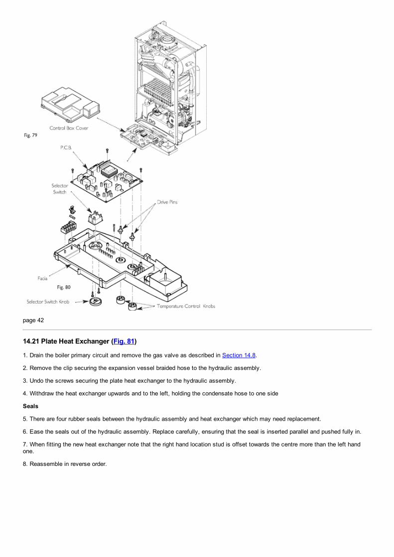
1. Note the settings of the temperature control knobs. Rotate the knobs fully anticlockwise and carefully pull them off the drive pins.
2. Completely undo the screws securing the control box cover and release the cover retaining barbs from their slots. Disengage therear of the cover from the control box hinge pin (Fig. 79).
3. Note the position of all plugs and wires on the P.C.B. and disconnect them.
4. Undo the securing screws and remove the P.C.B. Transfer the control knob drive pins to the new P.C.B. and turn them fullyanticlockwise.
5. Reassemble in reverse order, ensuring that the temperature controllers are reset to their previous positions.
14.20 Selector Switch (Fig. 80)
1. Note the setting of the selector switch knob and carefully pull it off the facia.
2. Completely undo the screws securing the control box cover and release the cover retaining barbs from their slots. Disengage therear of the cover from the control box hinge pin (Fig. 79).
3. Note the position of the electrical connections and the orientation of the switch. Remove the electrical connections.
4. Remove the screws securing the switch to the facia panel.
5. Fit the new switch, ensuring that it is correctly positioned and reassemble in reverse order.
page 42
14.21 Plate Heat Exchanger (Fig. 81)
1. Drain the boiler primary circuit and remove the gas valve as described in Section 14.8.
2. Remove the clip securing the expansion vessel braided hose to the hydraulic assembly.
3. Undo the screws securing the plate heat exchanger to the hydraulic assembly.
4. Withdraw the heat exchanger upwards and to the left, holding the condensate hose to one side
Seals
5. There are four rubber seals between the hydraulic assembly and heat exchanger which may need replacement.
6. Ease the seals out of the hydraulic assembly. Replace carefully, ensuring that the seal is inserted parallel and pushed fully in.
7. When fitting the new heat exchanger note that the right hand location stud is offset towards the centre more than the left handone.
8. Reassemble in reverse order.

14.22 Water Pressure Microswitch Assembly (Fig. 82)
1. Drain the boiler primary circuit.
2. Pull the two wires of the microswitch.
3. Draw the securing clip forwards to release the assembly. The clip is captive and does not need to be fully removed.
4. Reassemble in reverse order.

page 43
14.23 Flow Regulator & Filter (Fig. 83)
1. Pull out the securing clip and prise the regulator and filter assembly out of the hydraulic inlet block.
2. Twist the body to unlock the bayonet connection and remove the regulator.
3. Examine and clean the filter, and reassemble in reverse order.
14.24 DHW Flow Sensor ('Hall Effect' Sensor) (Fig. 84)
1. Pull the sensor off the DHW inlet manifold.
2. Disconnect the plug from the sensor and connect it to the new component.
3. Fit the new sensor, ensuring it is fully engaged over the manifold.
14.25 Diverter Valve Motor (Fig. 85)
1. Undo the screw securing the electrical plug to the motor unit. Disconnect the plug.
2. Hold the motor unit in place against the spring pressure of the valve and remove the securing clip.
3. Remove the motor.
4. When fitting the new motor it will be necessary to hold the unit firmly while depressing the valve return spring.

page 44
14.26 Secondary Heat Exchanger (Fig. 87)
1. Drain the primary circuit
2. Undo the four screws securing the right hand case panel. Remove the panel.

3. Prise the connecting clips from the heat exchanger return pipe and the boiler return pipe. Remove the pipes.
4. Remove the fan and hood assembly as described in Section 14.1
5. Remove the nut securing the elbow to the secondary heat exchanger. Draw the elbow and outlet pipe forwards.
6. Remove the secondary heat exchanger from the outer drum by easing it forward.
7. Reassemble in reverse order of dismantling.
Fig. 87
14.27 Flue Overheat Thermostat (Fig. 88)
NOTE: The flue overheat thermostat includes areset button. Check that the thermostat will notreset before replacing.
1. Remove the fan and hood assembly as described in Section 14.1
2. Pull the two wires off the terminals on the flue overheat thermostat. Unscrew the thermostat from the adaptor in the outlet elbow.
3. Reassemble in reverse order of dismantling.
Fig. 88

page 45
15.0 Illustrated Wiring Diagram

br brownbk blackb bluer redg greeng/y green /
yelloww white
page 46
16.0 Fault Finding

Carry out initial fault finding checks 1. Check that gas, water and electrical supplies are available at the boiler. Electrical supply = 230V ~ 50 Hz. CH water system pressurised 1.0 to 1.5 bar when the boiler is cold. The preferred minimum gas pressure is 19.5mbar(natural gas), or 36mbar (propane). 2. Carry out electrical system checks, i.e. Ground Continuity, Resistance to Ground, Short Circuit and Polarity with asuitable meter. NOTE: These checks must be repeated after any servicing or fault finding. 3. Ensure all external controls are calling for heat and check all external and internal fuses. Before any servicing orreplacement of parts ensure the gas and electrical supplies are isolated.
Refer to Section 15.0 "Illustrated Wiring Diagram" for position of numbered terminals
Central Heating Follow operational sequenceNOTE: When instructed to turn theselector to the reset position turn theselector switch fully anticlockwiseagainst the spring pressure to 'Reset'position and hold for 2 seconds toreset the boiler.

page 47
Domestic Hot Water Follow operational sequence

page 48
Fault Finding Solutions Sections A to E

page 49

page 50

page 51
17.0 Fault Indication Display1. The boiler has three neon indicators. The upper two function as boiler on and fault indicators.
2. Depending on the nature of the fault the upper two neons will illuminate, go off or flash.
3. There are five possible combinations, each indicating one or more fault conditions. These are described below.
A The flue or flue terminal is blocked or obstructed in some way, or there is an internal fault.

B The circulating pump is faulty or the system pressure has dropped. Check the system pressure. If the pressure is in the normalrange a pump fault is indicated.
C A fault on the boiler temperature sensor is indicated.
D The primary system or the boiler has overheated. Allow the boiler to cool. Turn the selector switch fully anticlockwise against thespring pressure to the 'Reset' position and hold for at least 2 seconds. If the boiler does not relight after resetting it is possible thatthe flue has overheated.
E The burner has failed to light, or incomplete lighting of the burner has occurred. Turn the selector switch fully anticlockwiseagainst the spring pressure to the 'Reset' position and hold for at least 2 seconds. If the boiler does not relight after resettingblockage of the condensate drain or trap has occurred.
page 52
18.0 Short Parts List Short Parts List
KeyNo.
G.C. No. Description ManufacturersPart No.
A H01106 Fan 5112627
B Igniter/SparkGenerator
5112385
C E94426 Gas Valve 5107339
D E66 411 Spark or 247384

SensingElectrode
E H01103 Injector 5112376
F SafetyThermostat
720064001
G H01108 Flue OverheatThermostat
5112395
H PCB 720063401
J PressureSwitch 24
720063601
K H01072 Burner 5112770
L FilterCartridge
720064201
M Diverter 720064401
N PressureGauge
720061901
O Hall Sensor 720061801
P E66 408 ElectrodeLead
248037
Q CH TempSensor
720064601
R DHW TempSensor
720064801
S Air Vent 720062001
T Pump 720063001
U Micro SwitchAssembly
720063201
AB C
D
E F G
HJ

L M
K
NO
RP
QS U
T
page 53
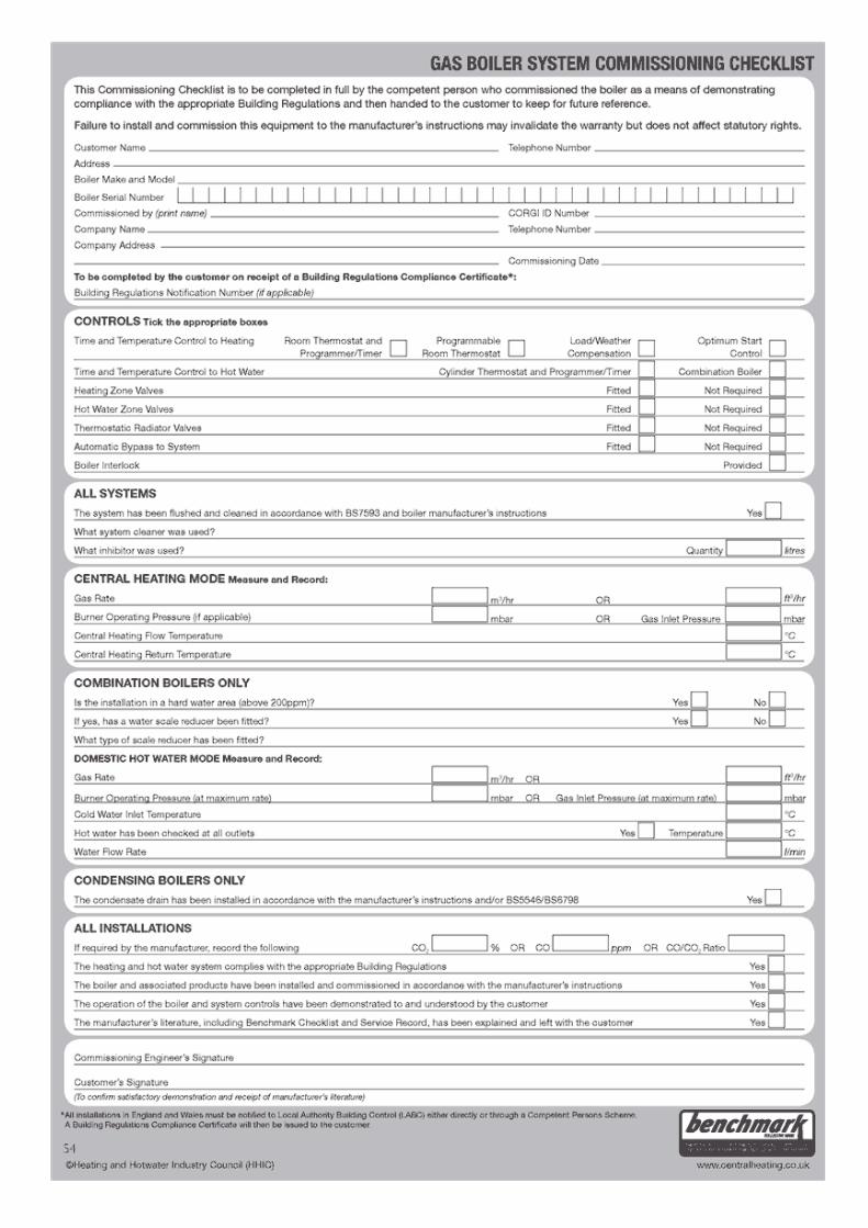

page 54


page 55
All descriptions and illustrations provided in this leaflet have been carefully prepared but we reserve the right to make changes andimprovements in our products which may affect the accuracy of the information contained in this leaflet. All goods are sold subjectto our standard Conditions of Sale which are available on request.
POTTERTON
A Trading Division of Baxi Heating UK Ltd (3879156)
A Division of Baxi Group
Brooks House, Coventry Road, Warwick. CV34 4LL After Sales Service 0844 871 1560 Technical Enquiries 0844 871 1555 Website www.potterton.co.uk
926.301.1
720060901 (4/09)
© Baxi Heating UK Ltd 2009
page 56