Embed Size (px)
Citation preview

InstallationSimplified…
by
April 2006

Cell Phones
As a courtesy to all,please set your cell phones to silent.
There will be a break toreturn phone calls

Installation

System Controller: Omni LT
EARTHGROUND
TRANSFORMER16.5VAC 40VA
AUXILIARY12VDC
SOUNDERCONSOLE(S) ZONE
INPUT INPUTZONE REMOTE
CONTROLTHERMOSTAT(S)
OUTPUT
OUTPUT
CONNECT CABLETO CONTROLLER,PLUG MODULAR
END INTORJ31X JACK
INPUTZONE
INPUTZONE
INPUTZONE
INPUTZONE
INPUTZONE
INPUTZONE
OUT2
BURGLARYZONE
ZONE
(NC)
1K EOL
ZONEUNIT AND DISCONNECT
Z8BEFORE SERVICING.TELEPHONE LINES
4-WIRE FIRE ZONE
EOL
COM
OUT2
SWITCH 12V
WARNING
DE-ENERGIZE THISFROM ELECTRIC SHOCK,TO PREVENT RISK
(NO)
SMOKE
ZN
12V
4-WIREZN
1K
12V
SMK
NRMJ9
2-WIRE FIRE ZONE
Z8
ZONE
ZN
SMOKE2-WIRE
12V
NRM
SMK
J9
AUXILIARY 12V, CONSOLE, AND OUTPUTS ARE INCLUDED IN THE TOTAL DEVICE LOAD, WHICH CANNOT EXCEED 0.5 AMP.
SOUNDERS CANNOT EXCEED 1 AMP. IN UL INSTALLATIONS, SOUNDERS CANNOT EXCEED 350mA.
NOTES:
3.
2.
(OUTPUT)
EOL1K
(OUTPUT)SWITCH 12V
ALL CIRCUITS EXCEPT FOR THE BATTERY ARE POWER-LIMITED (CLASS II)
IN UL INSTALLATIONS, THE TOTAL DEVICE LOAD CANNOT EXCEED 200mA.
1.

System Controller: Omni IIe / Pro II
EARTHGROUND
TRANSFORMER24 VAC 40 VA
INTERIORSOUNDER
SWITCHED12 VDC
AUXILIARY 12 VDCCONSOLE(S)
NOTES:1. SWITCH 12V, AUXILIARY 12V, CONSOLE, AND OUTPUTS 1-8 ARE INCLUDED IN THE TOTAL DEVICE LOAD, WHICH CANNOT EXCEED 1 AMP.
2. SOUNDERS CANNOT EXCEED 1 AMP, SPLIT BETWEEN INTERIOR AND EXTERIOR HORN OUTPUTS. IN UL INSTALLATIONS, SOUNDERS CANNOT EXCEED 350mA.
REMOTECONTROL
THERMOSTAT(S)
EXTERIORSOUNDER
1A Max.(See NOTE 1)
1A Max.(See NOTE 1)
(See NOTE 2)
ZONE (1-4)
IN4-WIRE FIRE ZONE
ZONE (1-4)
ZN1KEOL
SMOKE2-WIRE
12V
2-WIRE FIRE ZONE
SMK
NRM
COM
OUT
WARNINGSMOKE4-WIRE
12V
SWITCH 12V(OUTPUT)
12V
ZN
JP11-14
(OUTPUT)SWITCH 12V
INPUT
OUTPUT
ZN1KEOL
NRM
SMK
TO PREVENT RISKFROM ELECTRIC SHOCK,DE-ENERGIZE THISUNIT AND DISCONNECTTELEPHONE LINESBEFORE SERVICING.
OUTPUT
100 mA Max. (See NOTE 1)
OUTPUT OUTPUT OUTPUT OUTPUT OUTPUT OUTPUT
ALL CIRCUITS EXCEPT FOR THE BATTERYARE POWER-LIMITED (CLASS II)
CONNECT CABLETO CONTROLLER,PLUG MODULAREND INTORJ31X JACK
ZONEINPUT
ZONEINPUT
ZONEINPUT
ZONEINPUT
ZONEINPUT
ZONEINPUT
ZONEINPUT
ZONEINPUT
ZONES 1-16 ARE CONFIGURABLE FOR BURGLARY, FIRE, TEMPERATURE, OR AUXILIARY.2-WIRE SOMKE DETECTORS MAY ONLY BE CONNECTED TO ZONES 1-4.
INPUTZONE
INPUTZONE
INPUTZONEZONE
INPUTZONEINPUT
ZONEZONEINPUT INPUT
ONLY ZONES 9-16 MAY BE CONFIGURED AS ENERGY SAVER ZONES.ONLY ZONE 16 MAY BE USED FOR REMOTE CONTROL THERMOSTATS.
JP11-14
ZONEZONE ZONE
1K EOL 1K EOL 1K EOL
(NC)
(NO)
(NO)
(NC)
BURGLARY ZONES
IN UL INSTALLATIONS, THE TOTAL DEVICE LOAD CANNOT EXCEED 250mA.

Lumina and Lumina Pro
EARTHGROUND
TRANSFORMER24 VAC 40 VA
INTERIORSOUNDER
SWITCHED12 VDC
AUXILIARY 12 VDCCONSOLE(S)
NOTES:1. SWITCH 12V, AUXILIARY 12V, CONSOLE, AND OUTPUTS 1-8 ARE INCLUDED IN THE TOTAL DEVICE LOAD, WHICH CANNOT EXCEED 1 AMP.
2. SOUNDERS CANNOT EXCEED 1 AMP, SPLIT BETWEEN INTERIOR AND EXTERIOR HORN OUTPUTS. IN UL INSTALLATIONS, SOUNDERS CANNOT EXCEED 350mA.
REMOTECONTROL
THERMOSTAT(S)
EXTERIORSOUNDER
1A Max.(See NOTE 1)
1A Max.(See NOTE 1)
(See NOTE 2)
ZONE (1-4)
IN4-WIRE FIRE ZONE
ZONE (1-4)
ZN1KEOL
SMOKE2-WIRE
12V
2-WIRE FIRE ZONE
SMK
NRM
COM
OUT
WARNINGSMOKE4-WIRE
12V
SWITCH 12V(OUTPUT)
12V
ZN
JP11-14
(OUTPUT)SWITCH 12V
INPUT
OUTPUT
ZN1KEOL
NRM
SMK
TO PREVENT RISKFROM ELECTRIC SHOCK,DE-ENERGIZE THISUNIT AND DISCONNECTTELEPHONE LINESBEFORE SERVICING.
OUTPUT
100 mA Max. (See NOTE 1)
OUTPUT OUTPUT OUTPUT OUTPUT OUTPUT OUTPUT
ALL CIRCUITS EXCEPT FOR THE BATTERYARE POWER-LIMITED (CLASS II)
CONNECT CABLETO CONTROLLER,PLUG MODULAREND INTORJ31X JACK
ZONEINPUT
ZONEINPUT
ZONEINPUT
ZONEINPUT
ZONEINPUT
ZONEINPUT
ZONEINPUT
ZONEINPUT
ZONES 1-16 ARE CONFIGURABLE FOR BURGLARY, FIRE, TEMPERATURE, OR AUXILIARY.2-WIRE SOMKE DETECTORS MAY ONLY BE CONNECTED TO ZONES 1-4.
INPUTZONE
INPUTZONE
INPUTZONEZONE
INPUTZONEINPUT
ZONEZONEINPUT INPUT
ONLY ZONES 9-16 MAY BE CONFIGURED AS ENERGY SAVER ZONES.ONLY ZONE 16 MAY BE USED FOR REMOTE CONTROL THERMOSTATS.
JP11-14
ZONEZONE ZONE
1K EOL 1K EOL 1K EOL
(NC)
(NO)
(NO)
(NC)
BURGLARY ZONES
IN UL INSTALLATIONS, THE TOTAL DEVICE LOAD CANNOT EXCEED 250mA.

Power & Ground
Ground to good earth ground with thick wire for surge/lightning protection.
Connect transformer (use a good one with self reset capabilities)
Omni IIe and Pro II use 24 volt transformers
Omni LT uses 16 volt transformer
40 VA transformer
Lumina systems include a transformer and battery

Phone Line Seizure
RJ31X Jack Phone Access
Local Remote
Central Station Computer Access
Bend tab up if necessary to
ensure tight fit.R
ED
GR
AY
GR
EE
N
GR
AY
BR
OW
N

Security System Wiring
Door and window security contacts
Multiple contacts may be wired in series
+ Z1 - + Z2 -
Normally Closed Normally Open
Zones / Inputs

Z1
Normally Closed
Zon
es /
Inpu
ts
+
-
Window 1 Window 2 Window 3
Multiple Contacts On a Loop

Powered Devices
Motion Detectors CO Detectors Glass break
+ Z5 -
+Aux-
NCPwr
Note: Diagram shows a normally closed (NC) device. A normally open device can be used if the EOL is in parallel.

4 - Wire Smoke Detection
Note for 4-wire smokesstart on zone 5 (easier to wire)

2 - Wire Smoke Detection
It is recommended NOT to use2-wire smokes with sounders
(too much power draw)

RJ-31X Telco Jack
Line seizure to dial out in emergency
Ability to use in house phones

HAI Consoles & Touchscreens

Address Each Console & Touchscreen
Consoles: Push and hold 4 & up-arrow to get into console set up mode
Touchscreens: Tap and hold HAI logo to get into Touchscreen set up mode

Powerline Interface
For Lighting and Appliance control
Do not plug into surge strip HLC PIM plugs into Serial
Port X-10 plugs into X-10 jack

Serial Connection

Ethernet
Omni IIe, OmniPro II,
Lumina, and Lumina
Pro Controllers
Port 4369
128-bit AES (Advanced
Encryption Standard)
Use DNS service for
Dynamic IP if remote
access desired

Omni IIe / Pro II Security Expanders
•17A00 Expansion Enclosure•16 Zones and 16 voltage outputs•1 amp battery backed, monitored power supply – uses 24 V 40 VA transformer, 12 V battery•Ideal for powering touchscreens•Saves on homerun wiring•Up to 8 on OmniPro II
•10A06-1 Hardwire Expander•Mounts on Controller•16 Zones•Up to 2 on Omni II, Pro II
•22A00-1 OmniLT expansion module •16 Zones and 8 voltage outputs•Mounts on OmniLT controller

Thermostat Installation
HVAC wirescommunication
connector
Backlight jumpersensor

Thermostat Communication
Earth
GND
24VAC
INPUT
12V GND
SWITCH
12V GND 12V GND
AUXILIARY
12V GND A B
CONSOLE
INT GND EXT
HORN
1 GND 2 3 GND 4 5 GND 6 7 GND 8
OUTPUTS
GRN RED BRN GRY
PHONE
+ Z9 - + Z10 - + Z11 - + Z12 - + Z13 - + Z14 - + Z15 - + Z16 -
+ Z1 - + Z2 - + Z3 - + Z4 - + Z5 - + Z6 - + Z7 - + Z8 -
• Address: Mode Off, Prog 3x, Fan, Location 00, Fan to Exit
• Option 3, Value 5• Filter Reminder
• Turn off Option 15, Value 60

Communications Wiring Detail
When used with HAI controller, connect black AND red communication wires from thermostat to black wire, then black wire to COM at the controller. Wire as shown.
Omni IIe / Pro II / Lumina OmniLT
YE
LLO
W
GR
EE
N
BL A
CK

Address Thermostats
Be sure thermostats are working with HVAC system first (follow procedure in manual)
Enable thermostats in controller: Setup - Installer – Temperatures (9-#-5 on console) and set each thermostat to auto heat/cool
Press Prog Prog Prog Fan to get into set up mode Location 0 is the Thermostat Address Use ^ and v keys to change location value Set thermostats to consecutive addresses (1, 2, 3…) While you’re there, turn off internal scheduler (location 3 = 5) Use < and > keys while in set up to advance to next location Press FAN to exit set up or just let it time out Verify communications by Status-Temperature (6-5) on console –
you should see the thermostat temperature See the manual before you change anything else!!

Outdoor Temp
Earth
GND
24VAC
INPUT
12V GND
SWITCH
12V GND 12V GND
AUXILIARY
12V GND A B
CONSOLE
INT GND EXT
HORN
1 GND 2 3 GND 4 5 GND 6 7 GND 8
OUTPUTS
GRN RED BRN GRY
PHONE
+ Z9 - + Z10 - + Z11 - + Z12 - + Z13 - + Z14 - + Z15 - + Z16 -
+ Z1 - + Z2 - + Z3 - + Z4 - + Z5 - + Z6 - + Z7 - + Z8 -
31A00-7 Outdoor Sensor
No Direct Sunlight or Direct RainMount In a Covered Location
‘Weather resistant’ Not ‘Weather Proof’Mount Vertically

Power Up
Follow power up procedure in manual.
Check connections for shorts, opens, wire whiskers, tightness, etc.
Plug in transformer (system should power up: AC power LED comes on and status light flashes)
Connect Battery
Consoles will beep during power up and until addresses are set.
Test all zones and devices!

Setup
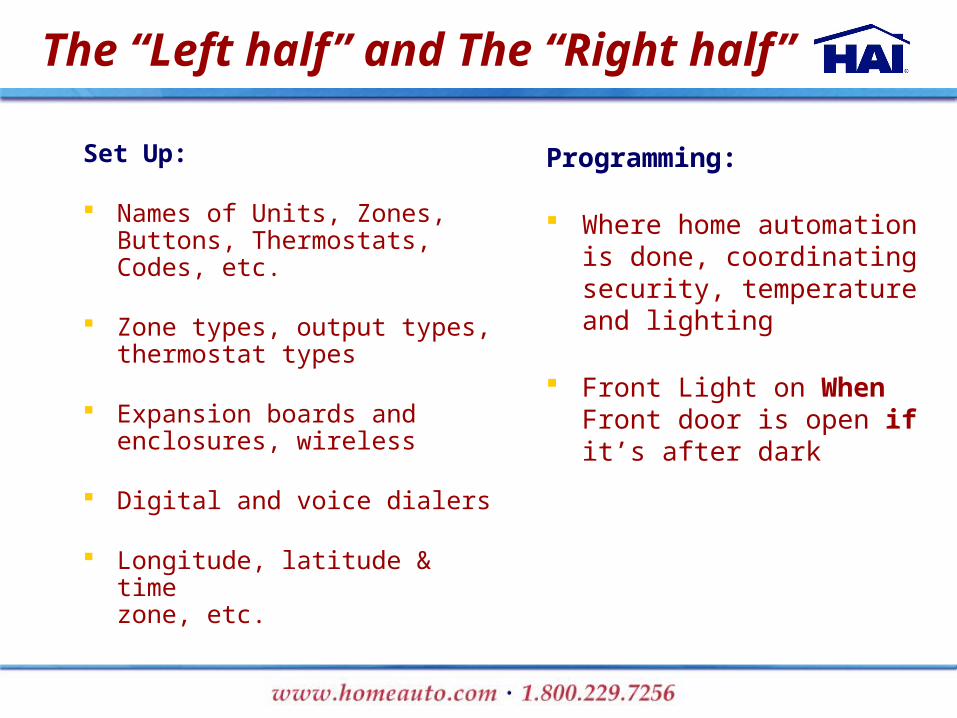
The “Left half” and The “Right half”
Set Up:
Names of Units, Zones, Buttons, Thermostats, Codes, etc.
Zone types, output types, thermostat types
Expansion boards and enclosures, wireless
Digital and voice dialers
Longitude, latitude & time zone, etc.
Programming:
Where home automation is done, coordinating security, temperature and lighting
Front Light on When Front door is open if it’s after dark

PCAccess
Create programs in PCAccess Review, edit delete, cut, paste,
copy
Search for programs Download to controller

Recommendation:Just Hit ‘Enter’
Security Stamp

Password
Default Password:‘Password’

Opening screen
Open or create a New File

Creating a New File

Creating a New File
Once a controller is selected the file data
can not be converted to a different controller
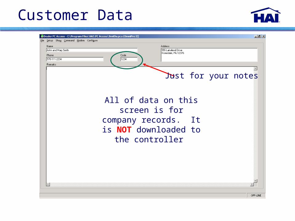
All of data on this screen is for company
records. It is NOT downloaded to the
controller
Just for your notes
Customer Data

Setup Names/Voice: Zones
Always Step 1
Note: Use Upper/Lowe
r Case
Note: Always
Choose the voice
descriptions when text is entered. It
is an excellent
habit!
Hardware cheat sheet: Z= Main Control Board; EX1-1 = Expander 1, Input 1;EE1-1 = Expansion Enclosure 1, Input 1

Setup Names/Voice: Tab Key

Setup Names/Voice: Units
HLC units are labeled on the right

1. HLC Configuration
HOUSE CONTROLLER
MASTER BEDROOM
LIVING ROOM CONTROLLER
DINING ROOM CONTROLLER
LIVING ROOM SWITCHES
DINING ROOM SWITCHES

Set up rooms with HLC
1: Living Room Controller 2: Chandelier 3: Sconces 4: Wall Wash 5: Lamps 6: Picture Spots 7: 8:
9: Den Room Controller 10: Lights 11: Cove 12: Lamps 13: Bar 14 15 16 House Controller
To Use HLC: Rooms are set up in
groups of 8 units The first unit in a room is
reserved for a room controller
The last unit can be used for a house controller
All you have to do is create the rooms and HLC does the rest

HLC Details
Standard HLC Configuration:
First unit in a group of 8 (1, 9, 17, 25, …) is reserved for Room Controller
Up to 7 loads (lights or appliances) per Room Controller
Up to 8 rooms per House Controller
OmniLT: 14 loads (2 rooms) Omni IIe and Lumina: 56 loads
(8 rooms) OmniPro II and Lumina Pro: 217
loads (30 rooms)
Example: Omni Controller automatically links 1: Living Room Controller with loads 2 – 8, and 9: Den Room Controller with loads 10 – 16.
Homeowner can easily adjust scenes for the different rooms.
Up to 8 House Controllers can be added anywhere “on the eights” in the first 64 units (example: unused unit 8 and/or 16) and it will control the first 8 rooms (64 units).
Loads and buttons are still fully controllable (and programmable) in Omni

Setup Names/Voice: Buttons
Note: Only use a
‘Button’ when the customer
should have manual
control of the routine. Use a flag
for ‘hidden’ routines

Note: Naming
users and assigning
them individual
codes makes
reading the even logs easier and
more informative.
Setup Names/Voice: Codes
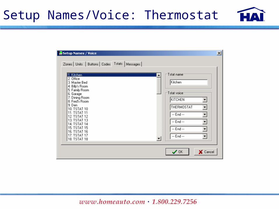
Setup Names/Voice: Thermostat

Displayed On Keypad
Spoken over the phone or out the 2-way voice
board
Note: The text and voice do not have to relate to each other but it does reduce
confusion
ASCII Messages Sent / Received through the RS-232 serial port
(ProLink)^M=Carriage
Return
Setup Names/Voice: Messages

Serial Configuration
Leave at 9600 Baud
Confirm the Correct Port
For Serial Connections: Code 1 in the software file MUST match Code 1 CURRENTLY in the controller. At default both are 1111. After 3 unsuccessful tries you are locked out. Pull the transformer and battery to power down the controller.

Network Configuration
For Network Connections: Code 1 in the software file MUST match Code 1 CURRENTLY in the controller. At default both are 1111. After 3 unsuccessful tries you are locked out. Pull the transformer and battery to power down the controller.
The Omni ProII uses a 10Base T connection
Change via console, serial or modem
Ethernet Options on the Console9, Valid Code, 6, (Scroll to Options)
Must be read from the console

Modem Configuration
Confirm the Correct Port
Leave at 19200 Baud
Modems should ‘auto
discover’LT = 300Omni II =
9600Pro II = 14.4K
For Modem Connections: Code 1 in the software file MUST match Code 1 CURRENTLY in the controller. At default both are 1111. After 3 unsuccessful tries you are locked out. Pull the transformer and battery to power down the controller.
Last 4 ones ‘1111’ is
the access code

Command: Set Time
Are we currently in
Daylight Savings Time?
Winter = NoSummer = Yes

Show / Status

A/D Reading0 - 255
Show / Status / Zones
Note: It is an excellent habit to always confirm hardware connections
Omni II / Pro II – Standard (non-smoke) readings:
0 – 20 = High Side Ground Fault 21 – 35 = Trouble36 – 80 = Low Side Ground Fault 81 – 110 = Trouble111 – 136 = Closed 137 – 157 = End Of Line (Secure)158 – 200 = Trouble 201 – 255 = Open

Show / Status / Units
This option is based on the last known
command to or from a
load.
Note: This can only be
reliable information if
2-way devices are
used
Note: When 2-way devices are used the controller will automatically update the status. Remember to set the PLC Communication protocol correctly.
Note: Double click a unit to
go to the unit/command
screen

Command / Units – Compose
Note: This screen shot is for a Unit
set for Compose. Based on
how the PLC format is set the ‘Scene’ command
will change to ‘Light Level’

Command / Units - Standard
Note: Notice the ‘Light
Level’ Option.‘Ramp’
refers to ALC options.
Off / On / Dim / Brighten:Perform the desired command for the time period, and then do the opposite.

Setup / Codes
Code 1 is the users most
powerful code. It is always a Master code
and will always allow access via PC Access
software.
Never set user 1 to 0,0,0,0.

Number is spoken during ‘dialed’ voice
notification for alarms.
Setup / Dial

Setup / Dial
T = 2 Second Pause

Loss of Phone is considered a
‘trouble’ condition
Setup / Arming
Should Say Entry/ Exit
and Perimeter Zone Type
Chime
All Lights On for Alarm
Technically is ‘Force Arm’
Yes/No?
Turn off when kids have
access to the console

Setup / Miscellaneous - Settings
Which light to flash in alarm?
Speak alarms out the 2-way voice board
A link is in the www.homeauto.com
dealer sectionUser: dealerPW: haidlr

Setup / Miscellaneous – Control
Standard: X10, PCS, Lightolier in Compatibility ModeExtended: Leviton, ACT A10Compose: Lightolier ComposeUPB: for non HAI UPB productsHLC: for HAI Lighting Control Products
Include this house code in the All On/Off Command?

Setup / Miscellaneous – Clocks
Time Clocks are used to
compare against in programs.
They are not time schedules.

Setup / Miscellaneous – DST

The 8 Outputs on the Main Control Board
Setup / Installer - Control
Set The UPB Network Address and Password

Setup / Installer - Zones
This refers to the
17A00 zone expansion cabinet, NOT the
10A06 zone expander
When Zone Resistors are turned off all zone inputs MUST be Normally Closed
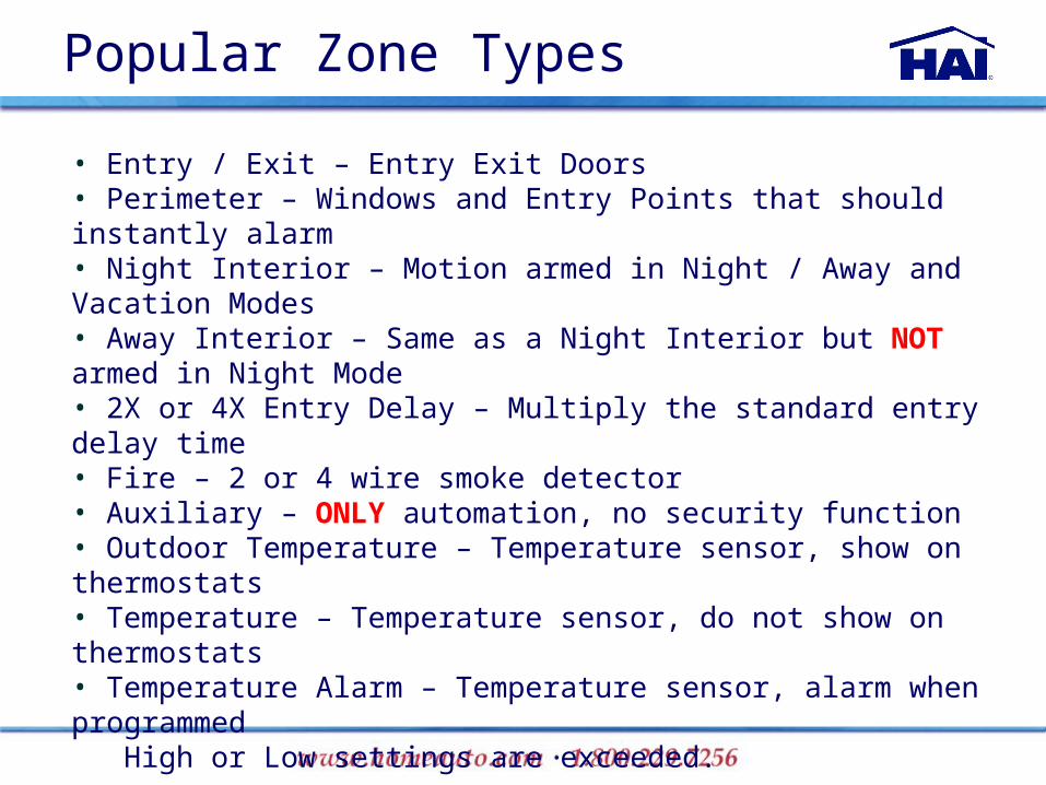
Popular Zone Types
• Entry / Exit – Entry Exit Doors• Perimeter – Windows and Entry Points that should instantly alarm• Night Interior – Motion armed in Night / Away and Vacation Modes• Away Interior – Same as a Night Interior but NOT armed in Night Mode• 2X or 4X Entry Delay – Multiply the standard entry delay time • Fire – 2 or 4 wire smoke detector• Auxiliary – ONLY automation, no security function• Outdoor Temperature – Temperature sensor, show on thermostats• Temperature – Temperature sensor, do not show on thermostats• Temperature Alarm – Temperature sensor, alarm when programmed High or Low settings are exceeded.

Always use Contact ID
when available
Setup / Installer - Communicator

Setup / Installer - Partitioning

Setup / Installer - Temperature

Setup / Installer - Miscellaneous
Only relates to access to
Installer menus on
the console
Only relates to access to modem call
in

‘0’ will keep the controller from looking for a phone line. Don’t forget to return to 8 once the
house has a phone line.
Setup / Installer - Miscellaneous

Setup / Installer - Miscellaneous
Turning off sounder supervision does not turn the supervision
current off

Setup / Installer - Expansion
Module # refers to the jumper in the upper left corner. Defaults are
1 – 10A06 Expander2 – ALC Board
3 – Serial Board
OmniLink – HAI
Programming Protocol
ProLink – Custom
written ASCII Messages
Leave at 0!

Consoles
You can do all set up and programming from the console, using the menus.
Allows you to get the basics up and running quickly in the field.
Programs can be added, edited or deleted.
Search capability.
Congratulations! You know how to install,
setup,
and program HAI Omni-
Family
automation systems.

What are the next steps?
Align yourself with an HAI
Distribution Partner
Purchase a system to install in
your home or office
Complete training special forms
Get HAI Tri-Folds to present to
your customers
Meet requirements to be listed on
HAI web-site
Sign up for HAI lead programs
Sign Up for e-mail news from HAI
Become a Five Star Dealer
Resources Sales & Marketing:
HAI Territory Manager
Tech Support:
800-229-7256 x 5
Pricing:
Distribution Partner

HAI Special Training Offers
Promo 11 Omni LT Package
Promo 14e Omni IIe Package
Promo 16 OmniPro II Package
*Refer to training flyer for details and limitations

Thanks forAttending!
We hope HAI can be a profitable part of your future!