Embed Size (px)
Citation preview

If you require any further assistance:
Telephone: 01698 820533Fax: 01698 825697
E-mail: [email protected] visit our website
www.electric-heatingcompany.co.uk
Electric Flow Boiler
InsTallaTIon &
TEchnIcal Manual

2GB-063C_f.706,7
Pleasereadandfollowtheinstallationoperatinginstructionscarefully,toensurethelonglifeandreliableoperationofthisappliance.TheElectricHeatingCompanymaymakeminorchangeswhennecessarytotheappliancethatwillnotbe
showninthisdocument,solongasthemainfeaturesoftheboilerremainthesame.Allboilerscomewitha24monthwarrantythatcoversalldefectsoriginatingfromfaultymaterialsandwork-
manshipinthemanufactureoftheboilers.Thewarrantywillnotcoveranydamagetotheboilerfrompoororincorrectinstallationwork.Inadditionthe
WarrantywillnotcoveranycalloutchargesthathavenotbeenauthorisedbytheElectricHeatingCompanyLtd.Thewarrantywillnotcoveranywaterleaksintotheboilerthatmaycausedamagetotheelectricalorelec-
troniccontrolsystem.Allplumbingconnectionsmustbecheckedandautoairventspositionedtothesideoftheboilerandnot
directlyabovetheunit.AMagneticFiltermustbeinstalledtotheboilersreturnpipeworkbeforethecirculationpump.Itisrecom-
mendedthatthefilteriscleaned;failuretocleantheMagneticFiltermayresultinboiler/systemfailure.War-rantycallswillnotbecoveredwheretheaboverequirementshavenotbeenmet.
The “Slim Jim” boiler is a low temperature boiler intended for use in unvented or vented central heating systems with forced circulation.
(Protected according to legally binding directives).
This appliance is not intended for use by persons (including children) with reduced physical, sensory or mental capabilities, or lack of experience and knowledge unless they have been given supervision or instruction concerning the use of the appliance by a person responsible for their safety.
Children should be supervised to ensure that they do not operate or interfere with the appliance.
Page Contents
INTRODUCTION 2PREPARATION 4LOCATION 4GENERAL 5BOILER INTERNAL LAYOUT 7INSTALLATION 8SYSTEM PROTECTION - COMMISSIONING 11ELECTRICAL CONNECTIONS 12ELECTRICAL CONNECTIONS 14ELECTRICAL DIAGRAM 15EXTERNAL CONTROL WIRING 17BOILER CONTROL PANEL 18TECHNICAL SPECIFICATION 19
INTRODUCTION
3GB-063C_f.706,7
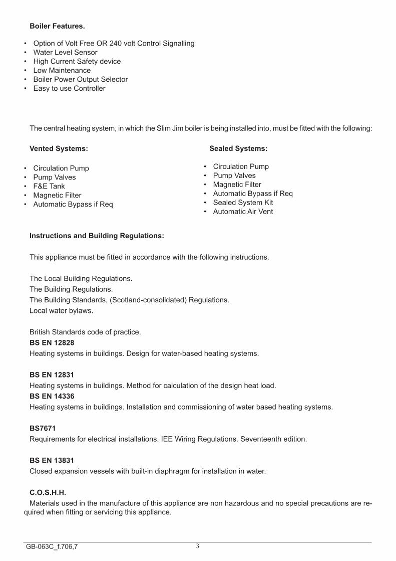
Boiler Features.
• OptionofVoltFreeOR240voltControlSignalling• WaterLevelSensor• HighCurrentSafetydevice• LowMaintenance• BoilerPowerOutputSelector• EasytouseController
Thecentralheatingsystem,inwhichtheSlimJimboilerisbeinginstalledinto,mustbefittedwiththefollowing:
Vented Systems:
• CirculationPump• PumpValves• F&ETank• MagneticFilter• AutomaticBypassifReq
Sealed Systems:
• CirculationPump• PumpValves• MagneticFilter• AutomaticBypassifReq• SealedSystemKit• AutomaticAirVent
Instructions and Building Regulations:
Thisappliancemustbefittedinaccordancewiththefollowinginstructions.
TheLocalBuildingRegulations.TheBuildingRegulations.TheBuildingStandards,(Scotland-consolidated)Regulations.Localwaterbylaws.
BritishStandardscodeofpractice.BS EN 12828Heatingsystemsinbuildings.Designforwater-basedheatingsystems.
BS EN 12831Heatingsystemsinbuildings.Methodforcalculationofthedesignheatload.BS EN 14336Heatingsystemsinbuildings.Installationandcommissioningofwaterbasedheatingsystems.
BS7671Requirementsforelectricalinstallations.IEEWiringRegulations.Seventeenthedition.
BS EN 13831 Closedexpansionvesselswithbuilt-indiaphragmforinstallationinwater.
C.O.S.H.H.Materialsusedinthemanufactureofthisappliancearenonhazardousandnospecialprecautionsarere-
quiredwhenfittingorservicingthisappliance.
4GB-063C_f.706,7
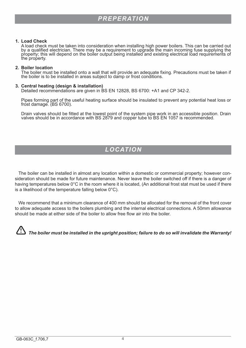
1. Load Check Aloadcheckmustbetakenintoconsiderationwheninstallinghighpowerboilers.Thiscanbecarriedout
byaqualifiedelectrician.Theremaybearequirementtoupgradethemainincomingfusesupplyingtheproperty;thiswilldependontheboileroutputbeinginstalledandexistingelectricalloadrequirementsoftheproperty.
2. Boiler location Theboilermustbeinstalledontoawallthatwillprovideanadequatefixing.Precautionsmustbetakenif
theboileristobeinstalledinareassubjecttodamporfrostconditions.
3. Central heating (design & installation) DetailedrecommendationsaregiveninBSEN12828,BS6700:+A1andCP342-2.
Pipesformingpartoftheusefulheatingsurfaceshouldbeinsulatedtopreventanypotentialheatlossorfrostdamage.(BS6700).
Drainvalvesshouldbefittedatthelowestpointofthesystempipeworkinanaccessibleposition.DrainvalvesshouldbeinaccordancewithBS2879andcoppertubetoBSEN1057isrecommended.
PREPERATION
LOCATION
Theboilercanbeinstalledinalmostanylocationwithinadomesticorcommercialproperty;howevercon-siderationshouldbemadeforfuturemaintenance.Neverleavetheboilerswitchedoffifthereisadangerofhavingtemperaturesbelow0°Cintheroomwhereitislocated,(Anadditionalfroststatmustbeusedifthereisalikelihoodofthetemperaturefallingbelow0°C).Werecommendthataminimumclearanceof400mmshouldbeallocatedfortheremovalofthefrontcover
toallowadequateaccesstotheboilersplumbingandtheinternalelectricalconnections.A50mmallowanceshouldbemadeateithersideoftheboilertoallowfreeflowairintotheboiler.
! The boiler must be installed in the upright position; failure to do so will invalidate the Warranty!
5GB-063C_f.706,7
GENERAL
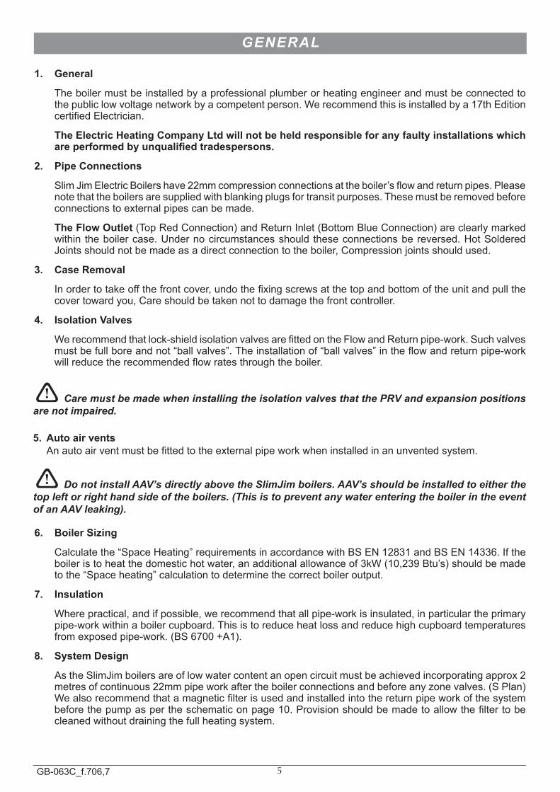
1. General
Theboilermustbeinstalledbyaprofessionalplumberorheatingengineerandmustbeconnectedtothepubliclowvoltagenetworkbyacompetentperson.Werecommendthisisinstalledbya17thEditioncertifiedElectrician.
The Electric Heating Company Ltd will not be held responsible for any faulty installations which are performed by unqualified tradespersons.
2. Pipe Connections
SlimJimElectricBoilershave22mmcompressionconnectionsattheboiler’sflowandreturnpipes.Pleasenotethattheboilersaresuppliedwithblankingplugsfortransitpurposes.Thesemustberemovedbeforeconnectionstoexternalpipescanbemade.
The Flow Outlet (TopRedConnection)andReturnInlet(BottomBlueConnection)areclearlymarkedwithin theboilercase.Undernocircumstancesshould theseconnectionsbereversed.HotSolderedJointsshouldnotbemadeasadirectconnectiontotheboiler,Compressionjointsshouldused.
3. Case Removal
Inordertotakeoffthefrontcover,undothefixingscrewsatthetopandbottomoftheunitandpullthecovertowardyou,Careshouldbetakennottodamagethefrontcontroller.
4. Isolation Valves
Werecommendthatlock-shieldisolationvalvesarefittedontheFlowandReturnpipe-work.Suchvalvesmustbefullboreandnot“ballvalves”.Theinstallationof“ballvalves”intheflowandreturnpipe-workwillreducetherecommendedflowratesthroughtheboiler.
! Care must be made when installing the isolation valves that the PRV and expansion positions are not impaired.
5. Auto air vents Anautoairventmustbefittedtotheexternalpipeworkwheninstalledinanunventedsystem.
! Do not install AAV’s directly above the SlimJim boilers. AAV’s should be installed to either the top left or right hand side of the boilers. (This is to prevent any water entering the boiler in the event of an AAV leaking).
6. Boiler Sizing
Calculatethe“SpaceHeating”requirementsinaccordancewithBSEN12831andBSEN14336.Iftheboileristoheatthedomestichotwater,anadditionalallowanceof3kW(10,239Btu’s)shouldbemadetothe“Spaceheating”calculationtodeterminethecorrectboileroutput.
7. Insulation
Wherepractical,andifpossible,werecommendthatallpipe-workisinsulated,inparticulartheprimarypipe-workwithinaboilercupboard.Thisistoreduceheatlossandreducehighcupboardtemperaturesfromexposedpipe-work.(BS6700+A1).
8. System Design
AstheSlimJimboilersareoflowwatercontentanopencircuitmustbeachievedincorporatingapprox2metresofcontinuous22mmpipeworkaftertheboilerconnectionsandbeforeanyzonevalves.(SPlan)Wealsorecommendthatamagneticfilterisusedandinstalledintothereturnpipeworkofthesystembeforethepumpaspertheschematiconpage10.Provisionshouldbemadetoallowthefiltertobecleanedwithoutdrainingthefullheatingsystem.
6GB-063C_f.706,7
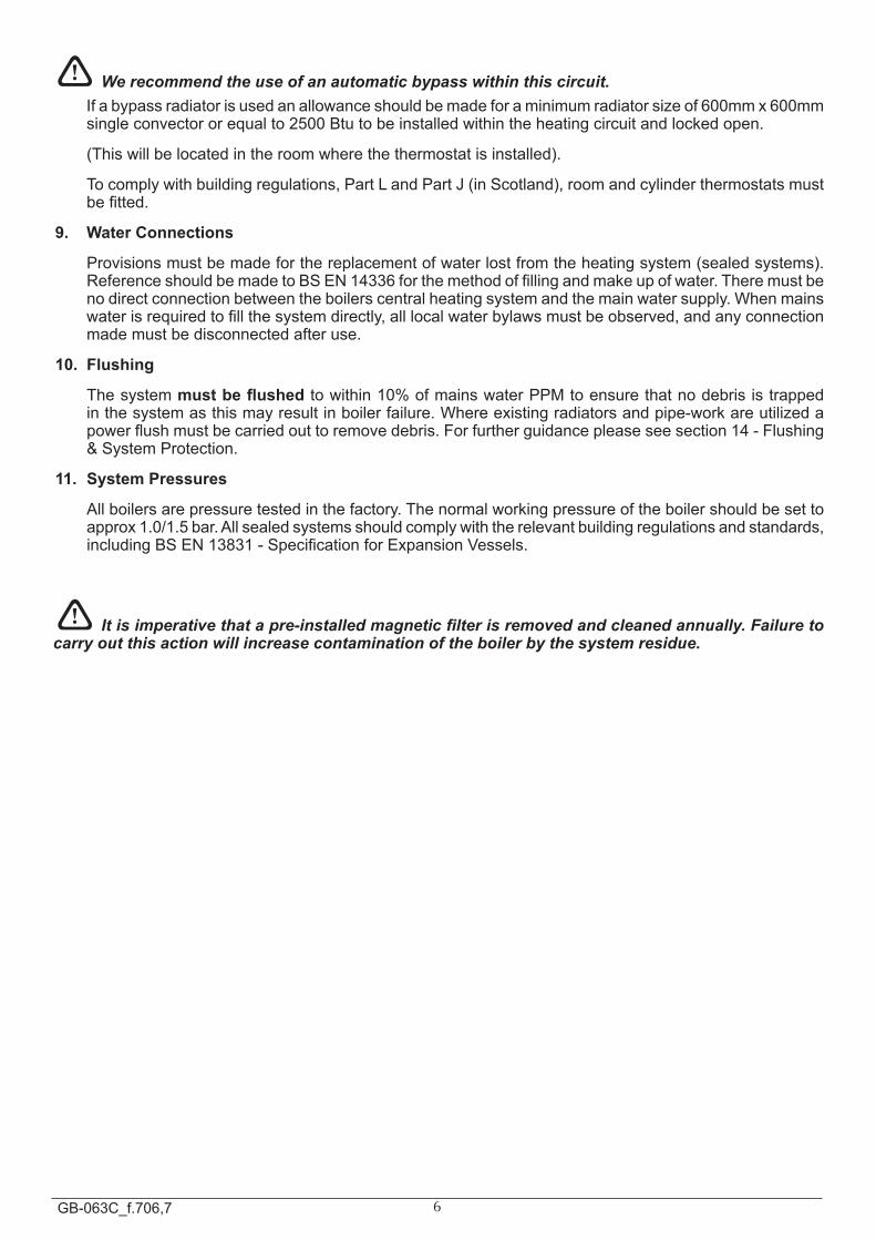
! We recommend the use of an automatic bypass within this circuit. Ifabypassradiatorisusedanallowanceshouldbemadeforaminimumradiatorsizeof600mmx600mm
singleconvectororequalto2500Btutobeinstalledwithintheheatingcircuitandlockedopen.
(Thiswillbelocatedintheroomwherethethermostatisinstalled).
Tocomplywithbuildingregulations,PartLandPartJ(inScotland),roomandcylinderthermostatsmustbefitted.
9. Water Connections
Provisionsmustbemadeforthereplacementofwaterlostfromtheheatingsystem(sealedsystems).ReferenceshouldbemadetoBSEN14336forthemethodoffillingandmakeupofwater.Theremustbenodirectconnectionbetweentheboilerscentralheatingsystemandthemainwatersupply.Whenmainswaterisrequiredtofillthesystemdirectly,alllocalwaterbylawsmustbeobserved,andanyconnectionmademustbedisconnectedafteruse.
10. Flushing
Thesystemmust be flushedtowithin10%ofmainswaterPPMtoensurethatnodebrisistrappedinthesystemasthismayresultinboilerfailure.Whereexistingradiatorsandpipe-workareutilizedapowerflushmustbecarriedouttoremovedebris.Forfurtherguidancepleaseseesection14-Flushing&SystemProtection.
11. System Pressures
Allboilersarepressuretestedinthefactory.Thenormalworkingpressureoftheboilershouldbesettoapprox1.0/1.5bar.Allsealedsystemsshouldcomplywiththerelevantbuildingregulationsandstandards,includingBSEN13831-SpecificationforExpansionVessels.
! It is imperative that a pre-installed magnetic filter is removed and cleaned annually. Failure to carry out this action will increase contamination of the boiler by the system residue.
7GB-063C_f.706,7
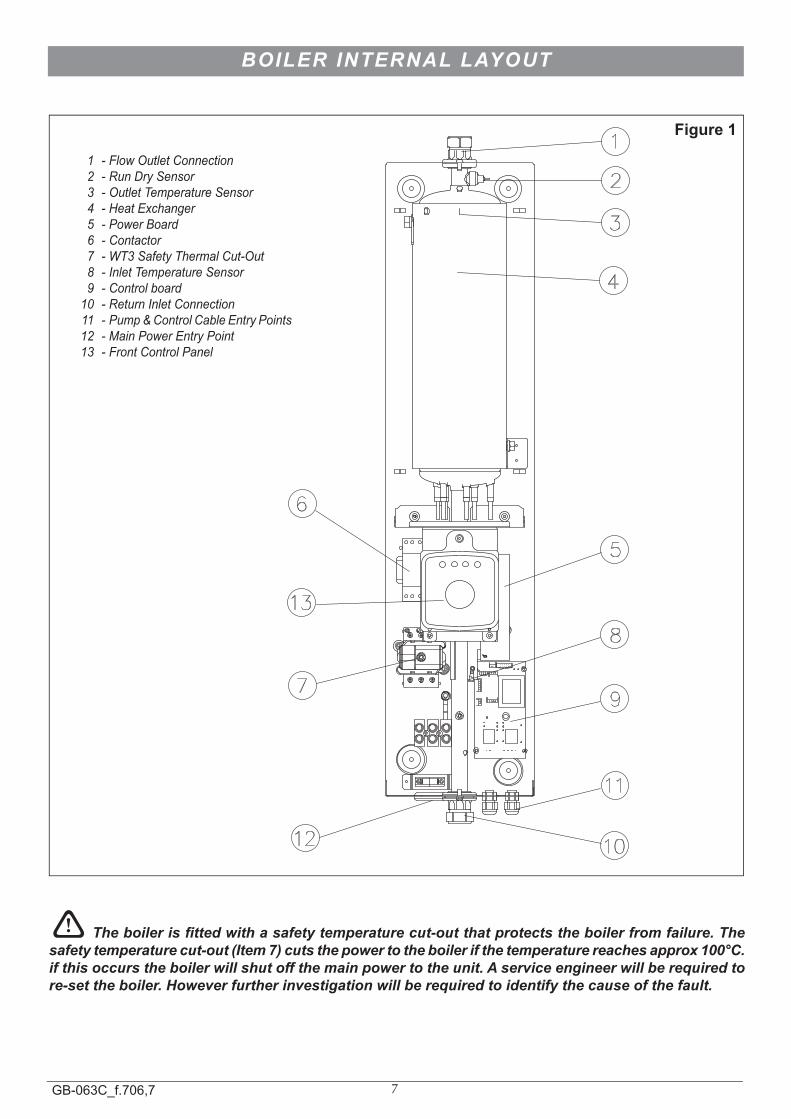
Figure 1
1 - Flow Outlet Connection 2 - Run Dry Sensor 3 - Outlet Temperature Sensor 4 - Heat Exchanger 5 - Power Board 6 - Contactor 7 - WT3 Safety Thermal Cut-Out 8 - Inlet Temperature Sensor 9 - Control board 10 - Return Inlet Connection 11 - Pump & Control Cable Entry Points 12 - Main Power Entry Point 13 - Front Control Panel
1
2
3
6
5
7
8
9
10
11
12
13
4
! The boiler is fitted with a safety temperature cut-out that protects the boiler from failure. The safety temperature cut-out (Item 7) cuts the power to the boiler if the temperature reaches approx 100°C. if this occurs the boiler will shut off the main power to the unit. A service engineer will be required to re-set the boiler. However further investigation will be required to identify the cause of the fault.
BOILER INTERNAL LAYOUT
8GB-063C_f.706,7
12. System types
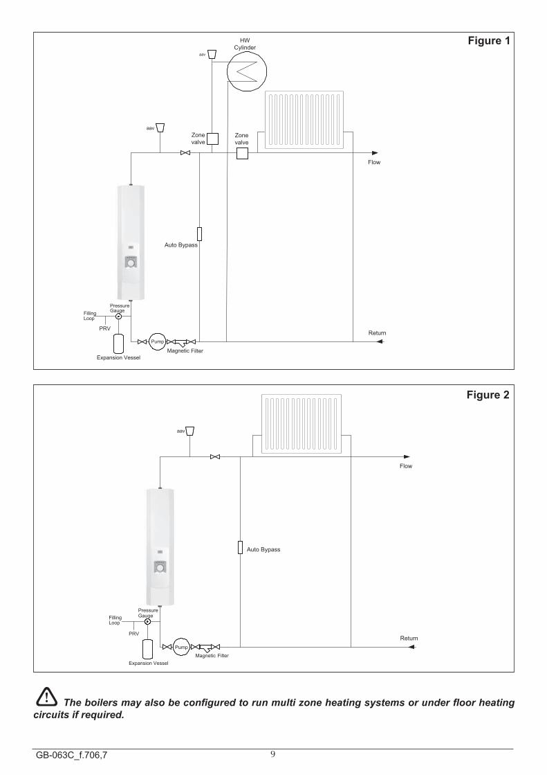
The“SlimJim”boilerrangecanbeusedinvarioussystemdesignsincludingunderfloorsystems.Therearetwoheatingschematicsonpage10Figure1&2thatillustrateanIndirectSystem(SPlan)&DirectSystem(HeatingOnly).
WerecommendtheuseofThermostaticRadiatorvalvesonallradiatorsexcludingthebypassradiator;thisradiatorshouldbefittedwithlockshieldvalvesandleftinthefullyopenposition.Inadditionwerecommendthatanautomaticbypassisusedinzonedsystemsandsettotherelevantflowratesrequiredforthesystemdesign.(Thebypassradiatorshouldbeaminimumsizeof600mmx600mmsingleconvectororequalto2500Btutobeinstalledwithintheheatingcircuitandlockedopen.Thiswillbelocatedinthesameareaastheroomthermostat).
! The system design should meet all current building regulations in force at the time of installation.
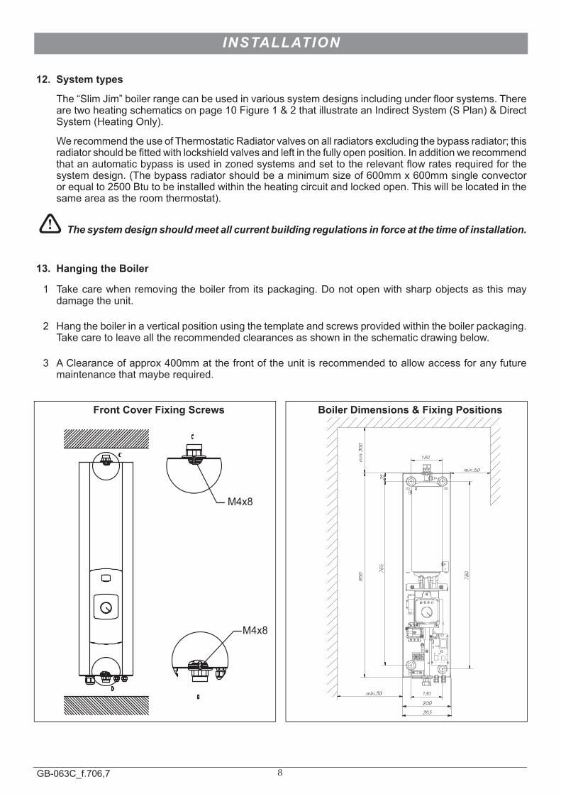
13. Hanging the Boiler
1 Takecarewhenremovingtheboilerfromitspackaging.Donotopenwithsharpobjectsasthismaydamagetheunit.
2 Hangtheboilerinaverticalpositionusingthetemplateandscrewsprovidedwithintheboilerpackaging.Takecaretoleavealltherecommendedclearancesasshownintheschematicdrawingbelow.
3 AClearanceofapprox400mmatthefrontoftheunitisrecommendedtoallowaccessforanyfuturemaintenancethatmayberequired.
INSTALLATION
M4x8
M4x8
C
DD
C
130
35
780
850
200
203
765
130
min.300
min.50
min.50
Front Cover Fixing Screws Boiler Dimensions & Fixing Positions
9GB-063C_f.706,7
Figure 2
aav
Expansion Vessel
Pump
Magnetic Filter
Gauge
PRV
Flow
Return
Filling Loop
Auto Bypass
aav
HW Cylinder
Zone valve
Zone valve
Pressure
aav
Expansion Vessel
Pump
Magnetic Filter
Gauge
PRV
Flow
Return
Filling Loop
Auto Bypass
Pressure
Figure 1
! The boilers may also be configured to run multi zone heating systems or under floor heating circuits if required.
10GB-063C_f.706,7
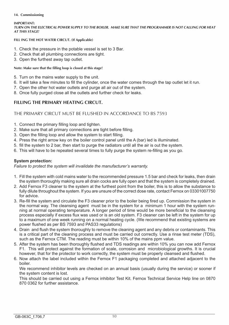
14. commissioning
IMPoRTanT: TURN ON THE ELECTRICAL POWER SUPPLY TO THE BOILER. MAKE SURE THAT THE PROGRAMMER IS NOT CALLING FOR HEAT AT THIS STAGE!
FIll InG ThE hoT WaTER cIRcuT. (If applicable)
1. Checkthepressureinthepotablevesselissetto3Bar.2. Checkthatallplumbingconnectionsaretight.3. Openthefurthestawaytapoutlet.
note: Make sure that the filling loop is closed at this stage!
5. Turnonthemainswatersupplytotheunit.6. Itwilltakeafewminutestofillthecylinder,oncethewatercomesthroughthetapoutletletitrun.7. Opentheotherhotwateroutletsandpurgeallairoutofthesystem.8. Oncefullypurgedclosealltheoutletsandfurthercheckforleaks.
FIllInG ThE PRIMaRY hEaTInG cIRcuT.
THE PRIMARY CIRCUT MUST BE FLUSHED IN ACCORDANCE TO BS 7593
1. Connecttheprimaryfillingloopandtighten.2.Makesurethatallprimaryconnectionsaretightbeforefilling.3. Openthefillingloopandallowthesystemtostartfilling.4. PresstherightarrowkeyontheboilercontrolpaneluntiltheA(bar)ledisilluminated.5. fillthesystemto2bar,thenstarttopurgetheradiatorsuntilalltheairisoutthesystem.6. Thiswillhavetoberepeatedseveraltimestofullypurgethesystemre-fillingasyougo.
System protection:Failure to protect the system will invalidate the manufacturer’s warranty.
1. Fillthesystemwithcoldmainswatertotherecommendedpressure1.5barandcheckforleaks,thendrainthesystemthoroughlymakingsurealldraincocksarefullyopenandthatthesystemiscompletelydrained.
2. AddFernoxF3cleanertothesystematthefurthestpointfromtheboiler,thisistoallowthesubstancetofullydilutethroughoutthesystem.Ifyouareunsureofthecorrectdoserate,contactFernoxon03301007750foradvice.
3. Re-fillthesystemandcirculatetheF3cleanerpriortotheboilerbeingfiredup.Commissionthesysteminthenormalway.Thecleansingagentmustbeinthesystemforaminimum1hourwiththesystemrun-ningatnormaloperatingtemperature.Alongerperiodoftimewouldbemorebeneficialtothecleansingprocessespeciallyifexcessfluxwasusedorisanoldsystem.F3cleanercanbeleftinthesystemforuptoamaximumofoneweekrunningonanormalheatingcycle.(WerecommendthatexistingsystemsarepowerflushedasperBS7593andPAS33regulations)
4. Drainandflushthesystemthoroughlytoremovethecleaningagentandanydebrisorcontaminants.Thisisacriticalpartofthecleaningprocessandmustbecarriedoutcorrectly.Usearinsetestmeter(TDS),suchastheFernoxCTM.Thereadingmustbewithin10%ofthemainsppmvalue.
5. AfterthesystemhasbeenthoroughlyflushedandTDSreadingsarewithin10%youcannowaddFernoxF1.Thiswillprotectagainsttheformationofscale,corrosionandmicrobiologicalgrowths.Itiscrucialhowever,thatfortheprotectortoworkcorrectly,thesystemmustbeproperlycleansedandflushed.
6. Nowattachthelabel includedwithintheFernoxF1packagingcompletedandattachedadjacenttotheboiler.
Werecommendinhibitorlevelsarecheckedonanannualbasis(usuallyduringtheservice)orsoonerifthesystemcontentislost.
ThisshouldbecarriedoutusingaFernoxinhibitorTestKit.FernoxTechnicalServiceHelplineon08708700362forfurtherassistance.
11GB-063C_f.706,7
SYSTEM PROTECTION - COMMISSIONING
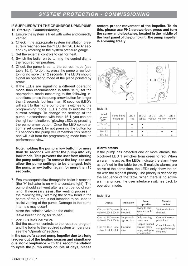
Rated power[kW]
Pump lifting height [m]
LED 1 red
LED 2yellow
LED 3yellow
LED 4yellow
LED 5yellow
4 4 - 7 5
10 - 12 6 12 - 14 7
Alarm statusIf thepumphasdetectedoneormorealarms, thebicoloredLED1switchesfromgreentored.Whenanalarmisactive,theLEDsindicatethealarmtypeasdefinedinthetablebelow.Ifmultiplealarmsareactiveatthesametime,theLEDsonlyshowtheer-rorwiththehighestpriority.Thepriorityisdefinedbythesequenceofthetable.Whenthereisnoactivealarmanymore,theuserinterfaceswitchesbacktooperationmode.
Display Indication Pump operation
counter action
One red LED + one yellow LED (LED 5)
Rotor is blocked.
Trying to start again every 1,5 seconds
Wait or deblock the shaft.
One red LED + one yellow LED (LED 4)
Supply volt-age too low
Only warning pump runs
Control the sup-ply voltage
One red LED + one yellow LED (LED 3)
Electrical error
Pump is stopped because of low supply voltage or serious failure
Control the supply voltage /Exchange the pump
LED
1 2 3 4 5
LED
IF SUPPLIED WITH THE GRUNDFOS UPM3 PUMP 15. Start-up / Commissioning1. Ensurethesystemisfilledwithwaterandcorrectly
vented.2. Checkiftheappropriatesysteminstallationpres-
sureisreached(seethe“TECHNICALDATA”sec-tion)byreferringtothesystempressuregauge.
3. Settheexternalcontrolstocallforheat.4. Switchtheboileronbyturningthecontroldialto
therequiredtemperature.5. Checkthepumpissettothecorrectmode(see
table15.1).Todothis,pressthepumparrowbut-tonfornomorethan2seconds.TheLED’sshouldsignalanoperatingmodeattheplacepointedbyarrow.
6. If the LEDs are signalling a different operatingmode than recommended in table 15.1, set theappropriatemodeaccording to the following in-structions:pressthepumparrowbuttonforlongerthan2seconds,butlessthan10seconds(LED’swillstart toflash),thepumpthenswitchestotheprogrammingmode.LEDsglows to indicate thecurrent settings.To change the settings of thepumpinaccordancewithtable15.1,youcansettherightcombinationofglowingLEDsbypressingthepumparrowbutton.OncetheLEDcombina-tionissetcorrect,bynotpressingthebuttonfor10secondsthepumpwillrememberthissettingandwillexitfromtheprogrammingmodebacktoperformanceview.
Note: holding the pump arrow button for more than 10 seconds will enter the pump into key lock mode. This prevents the user from altering the pump settings. To remove the key lock and allow the pump settings to be changed, hold the pump arrow button again for more than 10 seconds.
7. Ensureadequateflowthroughtheboilerisreached(the‘H’indicatorisonwithaconstantlight).Thepumpshouldselfventafterashortperiodofrun-ning. If necessary assist the ventingprocess inthefollowingway;Warningthescrewheadinthecentreofthepumpisnotintendedtobeusedtoassistventingofthepump,Damagetothepumpinternalsmayoccur!
• closetheisolationvalveontheoutlet,• leaveboilerrunningfor15sec.• opentheisolationvalve.8. Settheexternalcontrolstotherequiredprogram
andtheboilertotherequiredsystemtemperature,seethe“Operating”section.
In the case of a seized pump impeller due to a long layover out of the heating season and simultane-ous non-compliance with the recommendation to cycle the pump every couple of days, please
restore proper movement of the impeller. To do this, please use PH2 screwdriver, press and turn the screw anti-clockwise, located in the middle of the front panel of the pump until the pump impeller is spinning freely.
Table15.1
Table15.2
12GB-063C_f.706,7
ELECTRICAL CONNECTIONS
! All wiring must be carried out in accordance with current IEE wiring regulations BS:7671 (all electrical connections must be made by a qualified tradesperson).
LOAD CHECKAloadcheckmustbetakenintoconsiderationwheninstallinghighpowerboilers.Thiswillbecarriedoutbya
qualifiedelectrician.Theremaybeanadditionalrequirementtoupgradetheincomingmainfusesupplyingthepropertyifotherhighpowerdevicesareusedwithintheproperty.E.gElectricShowers.IfanelectricshowerispresentwerecommendthataShowerSensorisinstalledwithinthesystem.Thiswillcauseaninterrupttotheboilerscontrolsignalwhentheshowerisinuse.Itwilldisabletheboilerprotectingtheelectricalsystemfromoverload.Allboilersmustbeprotectedatthemeterpositionwitha30mAdoublepoleRCDwithaminimumof3mm
contactseparationaccompaniedbyasuitablyratedMCB.Iftheboilerisnotfittedlocaltothemeterpositionthenanadditionalisolationswitchmustbefittedlocaltotheboilerforeachsupply.Ifthepropertyispronetolighteningstrikesorpowercutsitisrecommendedtoinstallasuitablesurgeprotec-
tiondevicetotheboilersupply.Thiswillreducetheriskofdamagetotheboilerelectronicsduringtheseevents.THIS APPLIANCE MUST BE EARTHED.Allpipe-workmustbeearthedinaccordancewiththeIEEBS7671WiringRegulations.Aftercompletionofallelectricalworks,anelectricalsafetycheckshouldbecarriedouti.e.shortcircuit,earth
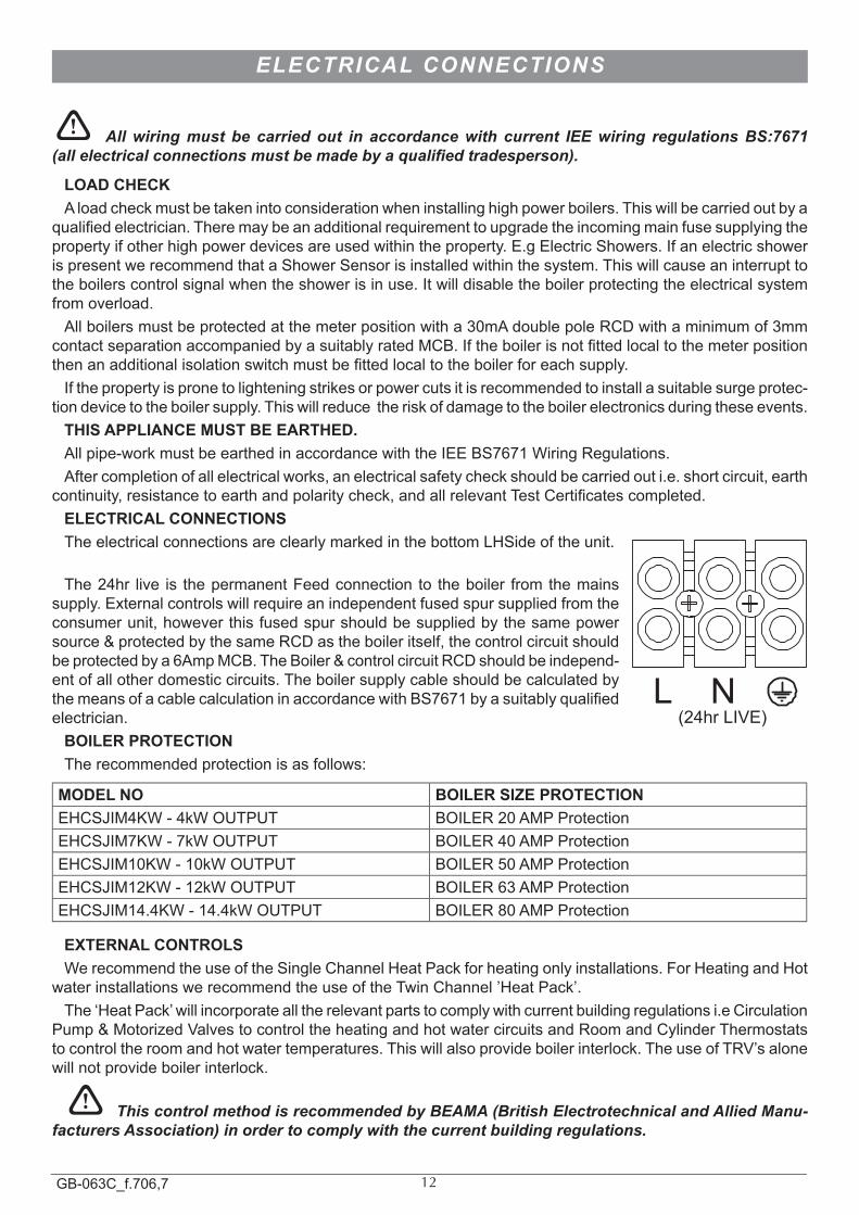
continuity,resistancetoearthandpolaritycheck,andallrelevantTestCertificatescompleted.ELECTRICAL CONNECTIONSTheelectricalconnectionsareclearlymarkedinthebottomLHSideoftheunit.
L N(24hrLIVE)
The24hr live is thepermanentFeedconnection to theboiler fromthemainssupply.Externalcontrolswillrequireanindependentfusedspursuppliedfromtheconsumerunit,howeverthisfusedspurshouldbesuppliedbythesamepowersource&protectedbythesameRCDastheboileritself,thecontrolcircuitshouldbeprotectedbya6AmpMCB.TheBoiler&controlcircuitRCDshouldbeindepend-entofallotherdomesticcircuits.TheboilersupplycableshouldbecalculatedbythemeansofacablecalculationinaccordancewithBS7671byasuitablyqualifiedelectrician.
BOILER PROTECTIONTherecommendedprotectionisasfollows:
MODEL NO BOILER SIZE PROTECTIONEHCSJIM4KW-4kWOUTPUT BOILER20AMPProtectionEHCSJIM7KW-7kWOUTPUT BOILER40AMPProtectionEHCSJIM10KW-10kWOUTPUT BOILER50AMPProtectionEHCSJIM12KW-12kWOUTPUT BOILER63AMPProtectionEHCSJIM14.4KW-14.4kWOUTPUT BOILER80AMPProtection
EXTERNAL CONTROLSWerecommendtheuseoftheSingleChannelHeatPackforheatingonlyinstallations.ForHeatingandHot
waterinstallationswerecommendtheuseoftheTwinChannel’HeatPack’.The‘HeatPack’willincorporatealltherelevantpartstocomplywithcurrentbuildingregulationsi.eCirculation
Pump&MotorizedValvestocontroltheheatingandhotwatercircuitsandRoomandCylinderThermostatstocontroltheroomandhotwatertemperatures.Thiswillalsoprovideboilerinterlock.TheuseofTRV’salonewillnotprovideboilerinterlock.
! This control method is recommended by BEAMA (British Electrotechnical and Allied Manu-facturers Association) in order to comply with the current building regulations.
13GB-063C_f.706,7
Slim JimBoiler
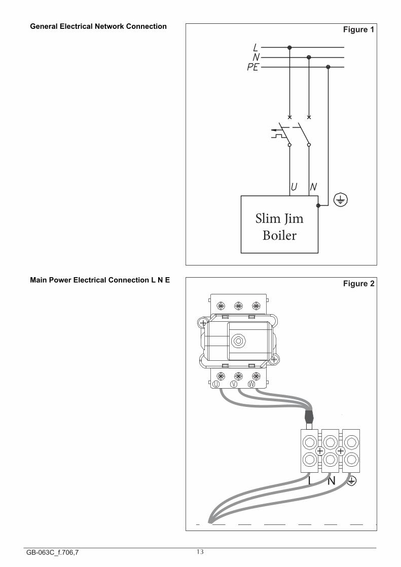
General Electrical Network Connection
L N
Main Power Electrical Connection L N E
Figure 1
Figure 2
14GB-063C_f.706,7
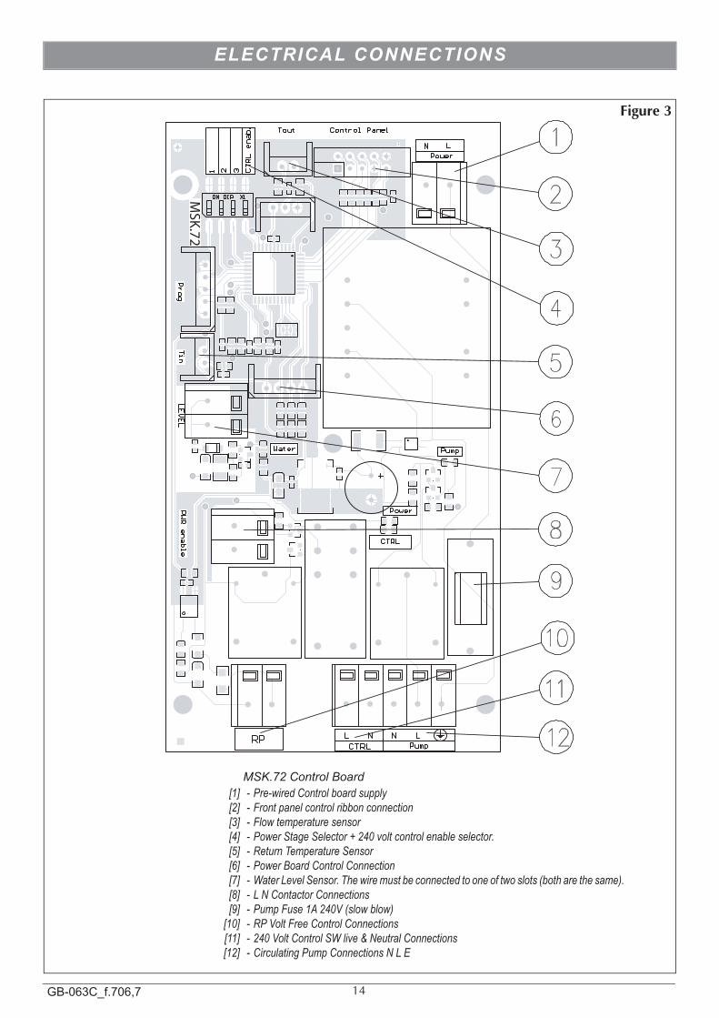
Figure 3
2
7
1
3
8
9
12
11
10
5
MSK.72
ELECTRICAL CONNECTIONS
MSK.72 Control Board [1] - Pre-wired Control board supply [2] - Front panel control ribbon connection [3] - Flow temperature sensor [4] - Power Stage Selector + 240 volt control enable selector. [5] - Return Temperature Sensor [6] - Power Board Control Connection [7] - Water Level Sensor. The wire must be connected to one of two slots (both are the same). [8] - L N Contactor Connections [9] - Pump Fuse 1A 240V (slow blow) [10] - RP Volt Free Control Connections [11] - 240 Volt Control SW live & Neutral Connections [12] - Circulating Pump Connections N L E
15GB-063C_f.706,7
ELECTRICAL DIAGRAM
1 2
3 RIK
L1G
1N
L2G
2L3
G3
A1
11a
22a
33a
NPE
23
XP
K
NU
21
ZM
RP
Pum
pC
TRL
A2
A3
X
NL
Tout
LEV
EL*
T1
S
E1
UN
Pow
er
21
UV
W
12
3F1 4
U 1
5 6
7 8
A1 A2
118
T2Ti
n
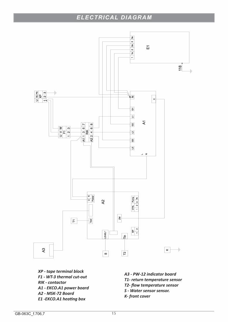
XP - tape terminal block F1 - WT-3 thermal cut-out RIK - contactorA1 - EKCO.A1 power board A2 - MSK-72 BoardE1 -EKCO.A1 heang box
A3 - PW-12 indicator board T1- return temperature sensor T2- flow temperature sensor S - Water sensor sensor.K- front cover
16GB-063C_f.706,7
Volt Free Control Signals
1 POWER STAGE VOLT FREE
2 POWER STAGE VOLT FREE
3 POWER STAGE VOLT FREE
240 Volt Control Signals
1 POWER STAGE 240 VOLT
2 POWER STAGE 240 VOLT
3 POWER STAGE 240 VOLT
Dip Switch Settings
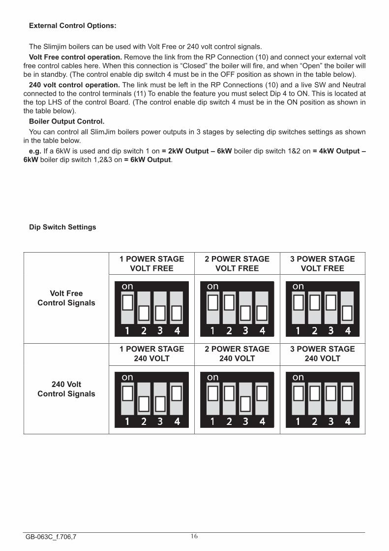
External Control Options:
TheSlimjimboilerscanbeusedwithVoltFreeor240voltcontrolsignals.Volt Free control operation.RemovethelinkfromtheRPConnection(10)andconnectyourexternalvolt
freecontrolcableshere.Whenthisconnectionis“Closed”theboilerwillfire,andwhen“Open”theboilerwillbeinstandby.(Thecontrolenabledipswitch4mustbeintheOFFpositionasshowninthetablebelow).
240 volt control operation.ThelinkmustbeleftintheRPConnections(10)andaliveSWandNeutralconnectedtothecontrolterminals(11)ToenablethefeatureyoumustselectDip4toON.ThisislocatedatthetopLHSofthecontrolBoard.(Thecontrolenabledipswitch4mustbeintheONpositionasshowninthetablebelow).
Boiler Output Control.YoucancontrolallSlimJimboilerspoweroutputsin3stagesbyselectingdipswitchessettingsasshown
inthetablebelow.e.g.Ifa6kWisusedanddipswitch1on= 2kW Output – 6kWboilerdipswitch1&2on= 4kW Output –
6kWboilerdipswitch1,2&3on= 6kW Output.
17GB-063C_f.706,7
EXTERNAL CONTROL WIRING
Figure 6
Figure 7
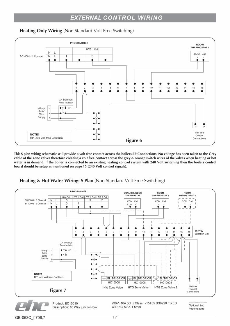
heating only Wiring (Non Standard Volt Free Switching)
This s plan wiring schematic will provide a volt free contact across the boilers RP connections. no voltage has been taken to the Grey cable of the zone valves therefore creating a volt free contact across the grey & orange switch wires of the valves when heating or hot water is in demand. If the boiler is connected to an existing heating control system with 240 Volt switching then the boilers control board should be setup as mentioned on page 15 (240 Volt control signals).
heating & hot Water Wiring: s Plan (Non Standard Volt Free Switching)
PROGRAMMERROOM
THERMOSTAT 2ROOM
THERMOSTAT 1DUAL CYLINDER
THERMOSTAT
11 12 13 14 1615
N LN L
3 43 5 7
HTG 1 CallHTG 1 CallHW Call HTG 2 Call
EC10002 - 2 ChannelEC10003 - 3 Channel COM Call
Volt freeControl
Connections
3A SwitchedFuse Isolator
6Amp240V50Hz
Supply N
NOTE! RP...are Volt free Contacts
COM CallCOM CallCOM
16 WayJunction Box
BLHC10008 HC10008 HC10008
HW Zone Valve HTG Zone Valve 1 HTG Zone Valve 2
BR GR OR BL BR GR OR BL BR GR OR
Product:EC10010Description:16Wayjunctionbox
--------------------Optional2ndheatingzone
230V~10A50HzClassII-15T55BS6220FIXEDWIRINGMAX1.5mm
PROGRAMMERROOM
THERMOSTAT 1
11 12 13 14 1615
N LN L
1
HTG 1 Call
3EC10001 - 1 ChannelCOM Call
Volt freeControl
Connections
3A SwitchedFuse Isolator
6Amp240V50Hz
Supply N
NOTE! RP...are Volt free Contacts
18GB-063C_f.706,7
BOILER CONTROL PANEL
OFF
030
40
1 3
5
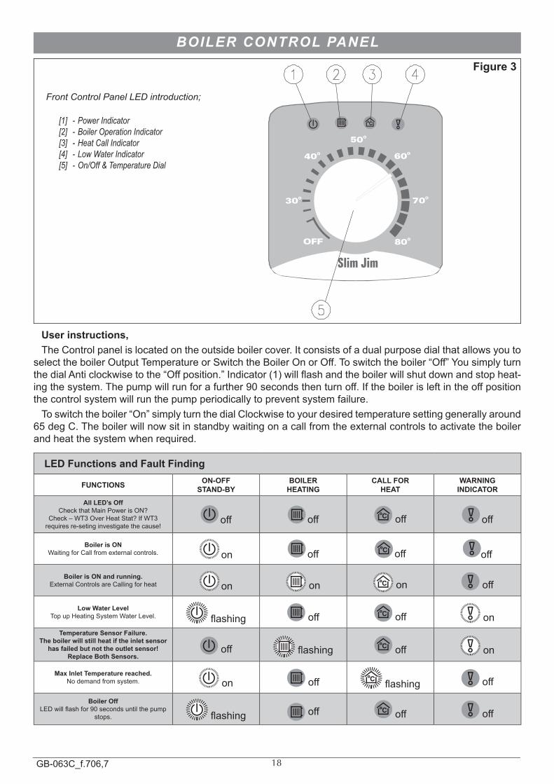
2 4Front Control Panel LED introduction;
[1] - Power Indicator [2] - Boiler Operation Indicator [3] - Heat Call Indicator [4] - Low Water Indicator [5] - On/Off & Temperature Dial
User instructions, TheControlpanelislocatedontheoutsideboilercover.Itconsistsofadualpurposedialthatallowsyouto
selecttheboilerOutputTemperatureorSwitchtheBoilerOnorOff.Toswitchtheboiler“Off”YousimplyturnthedialAnticlockwisetothe“Offposition.”Indicator(1)willflashandtheboilerwillshutdownandstopheat-ingthesystem.Thepumpwillrunforafurther90secondsthenturnoff.Iftheboilerisleftintheoffpositionthecontrolsystemwillrunthepumpperiodicallytopreventsystemfailure.Toswitchtheboiler“On”simplyturnthedialClockwisetoyourdesiredtemperaturesettinggenerallyaround
65degC.Theboilerwillnowsitinstandbywaitingonacallfromtheexternalcontrolstoactivatetheboilerandheatthesystemwhenrequired.
LED Functions and Fault Finding
FUNCTIONS ON-OFFSTAND-BY
BOILERHEATING
CALL FOR HEAT
WARNINGINDICATOR
All LED’s OffCheckthatMainPowerisON?
Check–WT3OverHeatStat?IfWT3requiresre-setinginvestigatethecause!
off off off off
Boiler is ON WaitingforCallfromexternalcontrols. on off off off
Boiler is ON and running.ExternalControlsareCallingforheat on on on off
Low Water LevelTopupHeatingSystemWaterLevel. flashing off off on
Temperature Sensor Failure.The boiler will still heat if the inlet sensor
has failed but not the outlet sensor!Replace Both Sensors.
off flashing off on
Max Inlet Temperature reached.Nodemandfromsystem. on off flashing off
Boiler OffLEDwillflashfor90secondsuntilthepump
stops. flashing off off off
Figure 3
19GB-063C_f.706,7
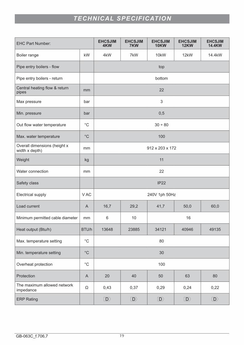
EHCPartNumber: EHCSJIM 4KW
EHCSJIM 7KW
EHCSJIM 10KW
EHCSJIM 12KW
EHCSJIM 14.4KW
Boilerrange kW 4kW 7kW 10kW 12kW 14.4kW
Pipeentryboilers-flow top
Pipeentryboilers-return bottom
Centralheatingflow&returnpipes mm 22
Maxpressure bar 3
Min.pressure bar 0,5
Outflowwatertemperature °C 30÷80
Max.watertemperature °C 100
Overalldimensions(heightxwidthxdepth) mm 912x203x172
Weight kg 11
Waterconnection mm 22
Safetyclass IP22
Electricalsupply VAC 240V1ph50Hz
Loadcurrent A 16,7 29,2 41,7 50,0 60,0
Minimumpermittedcablediameter mm 6 10 16
Heatoutput(Btu/h) BTU/h 13648 23885 34121 40946 49135
Max.temperaturesetting °C 80
Min.temperaturesetting °C 30
Overheatprotection °C 100
Protection A 20 40 50 63 80
Themaximumallowednetworkimpedance Ω 0,43 0,37 0,29 0,24 0,22
ERPRating D D D D D
TECHNICAL SPECIFICATION

Electric heating company ltdUnit 40, Block 5
Third RoadBlantyre Industrial Estate
BlantyreGlasgowG72 0UP
Tel: 01698 820533 Fax: 01698 825697
www.electric-heatingcompany.co.ukwww.ehc-renewables.co.uk
(Waste Electrical & Electronic Equipment)
(applicable in the European union and other European countries with separate collection systems).
This marking shown on the product or its literature, indicates that it should not be disposed of with other household wastes at the end of its working life.To prevent possible harm to the environment or human health from uncontrolled waste dis-posal, please separate this from other types of wastes and recycle it responsibly to promote the sustainable reuse of material resources. Household users should contact either the retailer where they purchased this product, or their local government office, for details of where and how they can take this item for environmentally safe recycling.Business users should contact their supplier and check the terms and conditions of the pur-chase contract. This product should not be mixed with other commercial wastes for disposal.