Embed Size (px)
Citation preview
303-01B-1 303-01B-1Engine — 4.6L (3V)
INSTALLATIONSpecial Tool(s)Cylinder Head
Installer, Front Cover Seal303-335 (T88T-6701-A)Special Tool(s)
Remover/Installer, CylinderHead303-572 (T97T-6000-A)
Modular Engine Lift Bracket303-F047 (014-00073) orequivalent
Alignment Pins, Cylinder Head303-1040 (SR-015486)
Material
Item SpecificationCompressor, Valve Spring
Motorcraft SAE 5W-20 WSS-M2C930-A303-1039Premium Synthetic BlendMotor OilXO-5W20-QSP (in CanadaMotorcraft SAE 5W-20Super Premium Motor OilCXO-5W20-LSP12) orequivalent
Locking Tool, Camshaft PhaserMotorcraft Premium Gold WSS-M97B51-A1SprocketEngine Coolant303-1046VC-7-A (in California,Oregon and New MexicoVC-7-B, in CanadaCVC-7-A) or equivalent(yellow color)
Silicone Gasket and WSE-M4G323-A4Installer, Crankshaft VibrationSealantDamperTA-30303-102 (T74P-6316-B)Motorcraft Metal Surface —PrepZC-31
Silicone Gasket Remover —ZC-30
Installer, Crankshaft Front Seal Hydraulic Chain Tensioner —303-635 Retaining Clip
1L3Z-6P250-AA
(Continued)
Copyright 2004, Ford Motor CompanyLast updated: 8/19/2005 2005 Mustang, 12/2004

303-01B-2 303-01B-2Engine — 4.6L (3V)
INSTALLATION (Continued)
All cylinder heads
1. CAUTION: Make sure all coolantresidue and foreign material are cleanedfrom the block surface and cylinder bore.
CAUTION: The use of sealing aids(aviation cement, copper spray and glue) isnot permitted. The gasket must be installeddry.
CAUTION: The cylinder head boltsmust be discarded and new bolts installed.They are tighten-to-yield designed andcannot be reused.
NOTE: Do not turn the crankshaft untilinstructed to do so.
NOTE: LH shown, RH similar.
Using the special tools, position the cylinderhead gaskets and cylinder heads over thedowels and install the cylinder head boltsloosely.
LH cylinder head
3. Remove the special tool from the LH cylinderhead.
2. NOTE: RH shown, LH similar.
Tighten the bolts in 3 stages, in the sequenceshown.
• Stage 1: Tighten to 40 Nm (30 lb-ft).
• Stage 2: Tighten an additional 90 degrees.
• Stage 3: Tighten an additional 90 degrees.
2005 Mustang, 12/2004

303-01B-3 303-01B-3Engine — 4.6L (3V)
INSTALLATION (Continued)
RH cylinder head4. NOTE: Lubricate the hydraulic lash adjusterswith clean engine oil prior to installation.
7. Remove the special tool from the RH cylinderNOTE: The hydraulic lash adjusters must behead.installed in their original locations.
Install the hydraulic lash adjusters into the LHcylinder head.
8. NOTE: Lubricate the hydraulic lash adjusterswith clean engine oil prior to installation.
NOTE: The hydraulic lash adjusters must be5. Position a new gasket, the LH exhaust manifoldinstalled in their original locations.and tighten the 8 nuts in the sequence shown.
Install the hydraulic lash adjusters into the RH• Tighten to 25 Nm (18 lb-ft).cylinder head.
6. Install the ground strap and nut to the stud bolt.
• Tighten to 10 Nm (89 lb-in).
2005 Mustang, 12/2004

303-01B-4 303-01B-4Engine — 4.6L (3V)
INSTALLATION (Continued)
All cylinder heads9. Position a new gasket, the RH exhaust manifoldand tighten the 8 nuts in the sequence shown.
12. NOTE: Lubricate the camshaft and camshaft• Tighten to 25 Nm (18 lb-ft).journals with clean engine oil prior toinstallation.
Install the LH and RH camshafts.
13. NOTE: LH shown, RH similar.
NOTE: Lubricate the camshaft bearing capswith clean engine oil.
Install the LH and RH camshaft bearing caps intheir original locations.
• Position the front camshaft bearing cap.
• Position the remaining camshaft bearingcaps.
• Install the bolts loosely.10. NOTE: Do not reuse the O-ring seals.• Tighten to 10 Nm (89 lb-in) in the sequenceNOTE: Lubricate the O-ring seals with clean
shown.engine coolant prior to installation.
Slide the coolant tube forward with the newO-ring seals into the cylinder block.
11. Install the coolant tube stud bolt.
• Tighten to 10 Nm (89 lb-in).
2005 Mustang, 12/2004
303-01B-5 303-01B-5Engine — 4.6L (3V)
INSTALLATION (Continued)
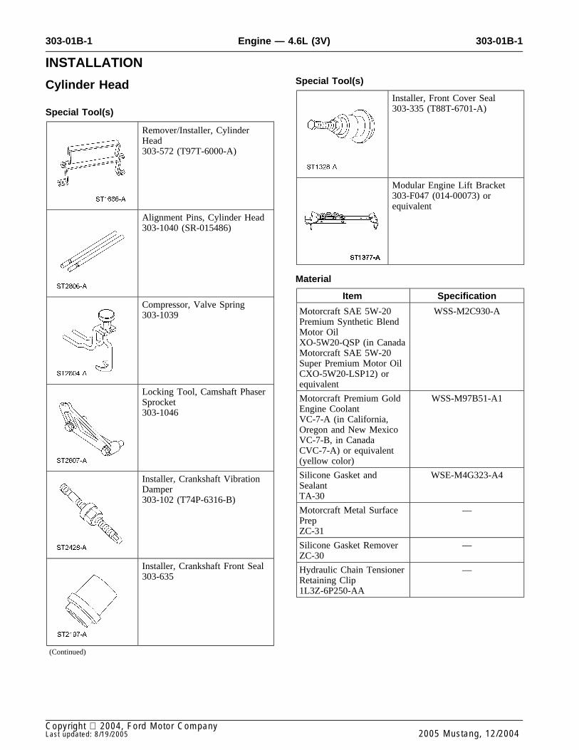
14. CAUTION: Damage to the camshaftphaser sprocket assembly will occur ifmishandled or used as a lifting or leveragingdevice.
NOTE: The RH and LH camshaft phasersprockets are similar. Refer to the single timingmark to identify the RH camshaft phasersprocket and the L timing mark to identify theLH camshaft phaser sprocket.
NOTE: LH shown, RH similar.
Install the camshaft phaser sprockets and newcamshaft phaser bolts finger tight.
16. Install the crankshaft sprocket, making sure theflange faces forward.
15. CAUTION: Damage to the camshaftphaser sprocket assembly will occur if
17. Rotate the crankshaft to position the crankshaftmishandled or used as a lifting or leveragingsprocket timing mark in the 6 o’clock position.device.
CAUTION: Only use hand tools toremove the camshaft phaser sprocketassembly or damage may occur to thecamshaft or camshaft phaser unit.
CAUTION: Damage to the camshaftphaser sprocket assembly will occur ifmishandled or used as a lifting or leveragingdevice.
NOTE: LH shown, RH similar.
Using the special tool, tighten the LH and RHcamshaft phaser sprocket bolts in 2 stages.
• Stage 1: Tighten to 40 Nm (30 lb-ft).
• Stage 2: Tighten an additional 90 degrees.
2005 Mustang, 12/2004

303-01B-6 303-01B-6Engine — 4.6L (3V)
INSTALLATION (Continued)
18. Rotate the camshaft sprockets to position the 21. Install a retaining clip on the tensioner to holdRH camshaft sprocket timing mark in the 11 the plunger in during installation.o’clock position and the LH camshaft sprockettiming mark in the 12 o’clock position.
22. Remove the tensioner from the vise.
23. If the copper links are not visible, mark one19. CAUTION: If one or both tensionerlink on one end and one link on the other endmounting bolts are loosened or removed, theand use as timing marks.tensioner-sealing bead must be inspected for
seal integrity. Any cracks, tears, cuts orseparation from the tensioner body, orpermanent compression of the seal bead, willrequire replacement of the tensioner.
Inspect the RH and LH timing chain tensioners.
• Install new tensioners, as necessary.
20. CAUTION: Timing chain proceduresmust be followed exactly or damage to valvesand pistons will result.
Compress the tensioner plunger, using a vise.
2005 Mustang, 12/2004
303-01B-7 303-01B-7Engine — 4.6L (3V)
INSTALLATION (Continued)
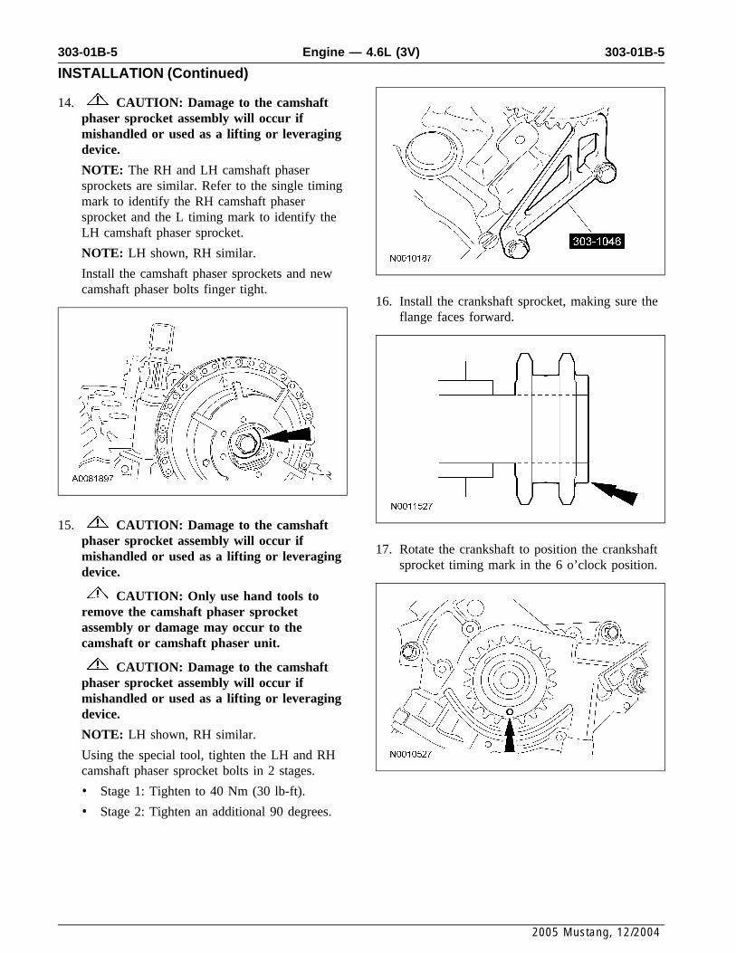
24. Install the 4 bolts and the LH and RH timingchain guides.
• Tighten to 10 Nm (89 lb-in).
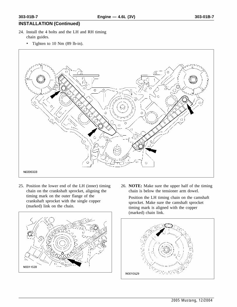
25. Position the lower end of the LH (inner) timing 26. NOTE: Make sure the upper half of the timingchain on the crankshaft sprocket, aligning the chain is below the tensioner arm dowel.timing mark on the outer flange of the Position the LH timing chain on the camshaftcrankshaft sprocket with the single copper sprocket. Make sure the camshaft sprocket(marked) link on the chain. timing mark is aligned with the copper
(marked) chain link.
2005 Mustang, 12/2004

303-01B-8 303-01B-8Engine — 4.6L (3V)
INSTALLATION (Continued)
27. NOTE: The LH timing chain tensioner arm hasa bump near the dowel hole for identification.
Position the LH timing chain tensioner arm onthe dowel pin and install the LH timing chaintensioner and 2 bolts.
• Tighten to 25 Nm (18 lb-ft).
30. NOTE: The lower half of the timing chainmust be positioned above the tensioner armdowel.
Position the RH timing chain on the camshaftsprocket. Make sure the camshaft sprockettiming mark is aligned with the copper(marked) chain link.
28. Remove the retaining clip from the LH timingchain tensioner.
31. Position the RH timing chain tensioner arm onthe dowel pin and install the RH timing chaintensioner and 2 bolts.29. Position the lower end of the RH (outer) timing
chain on the crankshaft sprocket, aligning the • Tighten to 25 Nm (18 lb-ft).timing mark on the sprocket with the singlecopper (marked) chain link.
2005 Mustang, 12/2004

303-01B-9 303-01B-9Engine — 4.6L (3V)
INSTALLATION (Continued)
32. Remove the retaining clip from the RH timing 34. Install the crankshaft sensor ring on thechain tensioner. crankshaft.
33. NOTE: The RH and LH camshaft phaser 35. NOTE: Lubricate the roller followers withsprockets are similar. Refer to the single timing clean engine oil prior to installation.mark to identify the RH camshaft phaser Using the special tool, install all of thesprocket and the L timing mark to identify the camshaft roller followers.LH camshaft phaser sprocket.
As a post-check, verify correct alignment of alltiming marks. Make sure the timing marks onthe sprockets correspond to the above note.
2005 Mustang, 12/2004

303-01B-10 303-01B-10Engine — 4.6L (3V)
INSTALLATION (Continued)
36. CAUTION: Do not use metal scrapers,wire brushes, power abrasive discs or otherabrasive means to clean the sealing surfaces.These tools cause scratches and gouges whichmake leak paths. Use a plastic scraping toolto remove all traces of old sealant.
NOTE: If the engine front cover is not securedwithin 4 minutes, the sealant must be removedand the sealing area cleaned. To clean thesealing area, use silicone gasket remover andmetal surface prep. Follow the directions on thepackaging. Failure to follow this procedure cancause future oil leakage.
NOTE: Make sure that the engine front covergasket is in place on the engine front coverbefore installation.
Apply a bead of silicone gasket and sealantalong the cylinder head-to-cylinder blocksurface at the locations shown.
2005 Mustang, 12/2004

303-01B-11 303-01B-11Engine — 4.6L (3V)
INSTALLATION (Continued)
Part37. Install a new engine front cover gasket on theItem Number Descriptionengine front cover. Position the engine front
14 N806300 Stud, Hex Shoulder Pilot, M8cover onto the dowels. Install the 15 fastenersx 1.25 x 1.25 x 91.1finger-tight.
15 N806300 Stud, Hex Shoulder Pilot, M8x 1.25 x 1.25 x 91.1
38. Tighten the 15 engine front cover fasteners inthe sequence shown to 25 Nm (18 lb-ft).
PartItem Number Description
1 N806177 Bolt, Hex Flange Head Pilot,M8 x 1.25 x 53
2 N806177 Bolt, Hex Flange Head Pilot,M8 x 1.25 x 53
3 N806177 Bolt, Hex Flange Head Pilot,M8 x 1.25 x 53
4 N806177 Bolt, Hex Flange Head Pilot,M8 x 1.25 x 53
5 N806177 Bolt, Hex Flange Head Pilot,M8 x 1.25 x 53
6 W706508 Stud, Hex Shoulder Pilot, M8x 1.25 x 50 - M6 x 1 x 10 39. Loosely install the 4 bolts, then tighten the
bolts in 2 stages, in the sequence shown.7 N808586 Stud and Washer, Hex HeadPilot, M8 x 1.25 - M6 x 1 x • Stage 1: Tighten to 20 Nm (15 lb-ft).86.35
• Stage 2: Tighten an additional 60 degrees.8 N806177 Bolt, Hex Flange Head Pilot,
M8 x 1.25 x 53
9 N806177 Bolt, Hex Flange Head Pilot,M8 x 1.25 x 53
10 N806177 Bolt, Hex Flange Head Pilot,M8 x 1.25 x 53
11 N806177 Bolt, Hex Flange Head Pilot,M8 x 1.25 x 53
12 N806300 Stud, Hex Shoulder Pilot, M8x 1.25 x 1.25 x 91.1
13 N806300 Stud, Hex Shoulder Pilot, M8x 1.25 x 1.25 x 91.1
2005 Mustang, 12/2004

303-01B-12 303-01B-12Engine — 4.6L (3V)
INSTALLATION (Continued)
40. Lubricate the engine front cover and thecrankshaft seal inner lip with clean engine oil.
43. Using the special tool, install the crankshaftpulley.
41. Using the special tools, install the crankshaftfront oil seal into the engine front cover.
44. Using a new crankshaft pulley bolt, install thebolt and washer and tighten the bolt in 4 stages.
• Stage 1: Tighten to 90 Nm (66 lb-ft).42. NOTE: If not secured within 4 minutes, the
• Stage 2: Loosen 360 degrees.sealant must be removed and the sealing areacleaned with metal surface prep and silicone • Stage 3: Tighten to 50 Nm (37 lb-ft).gasket remover. Allow to dry until there is no • Stage 4: Tighten an additional 90 degrees.sign of wetness, or 4 minutes, whichever islonger. Failure to follow this procedure cancause future oil leakage.
Apply silicone gasket and sealant to theWoodruff key slot in the crankshaft pulley.
2005 Mustang, 12/2004

303-01B-13 303-01B-13Engine — 4.6L (3V)
INSTALLATION (Continued)
45. Install the RH side accessory drive belt idler 48. NOTE: Lubricate the new O-ring seal withpulley, the coolant pump pulley and the 5 bolts. clean engine oil prior to installation.
• Tighten to 25 Nm (18 lb-ft). Install the RH CMP sensor and the bolt.
• Tighten to 10 Nm (89 lb-in).
46. Install the crankshaft position (CKP) sensor andthe bolt.
49. CAUTION: Do not use metal scrapers,• Tighten to 10 Nm (89 lb-in). wire brushes, power abrasive discs or other
abrasive means to clean sealing surfaces.These tools cause scratches and gouges whichmake leak paths. Use a plastic scraping toolto remove all traces of old sealant.
Clean the valve cover mating surface withsilicone gasket remover and metal surface prep.Follow the directions on the packaging.
50. NOTE: If not secured within 4 minutes, thesealant must be removed and the sealing areacleaned. To clean the sealing area, use siliconegasket remover and metal surface prep. Followthe directions on the packaging. Failure tofollow this procedure can cause future oil47. NOTE: Lubricate the new O-ring seal withleakage.clean engine oil prior to installation.Apply silicone gasket and sealant in 2 placesInstall the LH camshaft position (CMP) sensorwhere the engine front cover meets the cylinderand the bolt.head.
• Tighten to 10 Nm (89 lb-in).
2005 Mustang, 12/2004
303-01B-14 303-01B-14Engine — 4.6L (3V)
INSTALLATION (Continued)
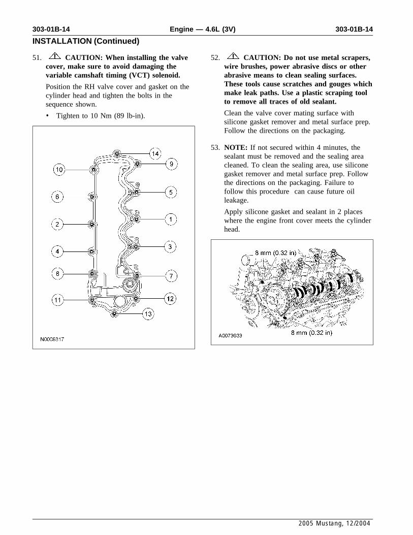
51. CAUTION: When installing the valve 52. CAUTION: Do not use metal scrapers,cover, make sure to avoid damaging the wire brushes, power abrasive discs or othervariable camshaft timing (VCT) solenoid. abrasive means to clean sealing surfaces.
These tools cause scratches and gouges whichPosition the RH valve cover and gasket on themake leak paths. Use a plastic scraping toolcylinder head and tighten the bolts in theto remove all traces of old sealant.sequence shown.Clean the valve cover mating surface with• Tighten to 10 Nm (89 lb-in).silicone gasket remover and metal surface prep.Follow the directions on the packaging.
53. NOTE: If not secured within 4 minutes, thesealant must be removed and the sealing areacleaned. To clean the sealing area, use siliconegasket remover and metal surface prep. Followthe directions on the packaging. Failure tofollow this procedure can cause future oilleakage.
Apply silicone gasket and sealant in 2 placeswhere the engine front cover meets the cylinderhead.
2005 Mustang, 12/2004

303-01B-15 303-01B-15Engine — 4.6L (3V)
INSTALLATION (Continued)
54. CAUTION: When installing the valvecover, make sure to avoid damaging thevariable camshaft timing (VCT) solenoid.
Position the LH valve cover and gasket on thecylinder head and tighten the bolts in thesequence shown.
• Tighten to 10 Nm (89 lb-in).
56. Install a new oil filter.
57. NOTE: LH shown, RH similar.
Install the 8 ignition coils and the 8 bolts.
• Tighten to 6 Nm (53 lb-in).
58. Position the engine wiring harness on theengine.
55. Install the oil level indicator tube and the bolt. 59. Connect the engine oil pressure sensor electricalconnector.• Install a new O-ring seal and lubricate the
O-ring seal with clean engine oil prior toinstallation.
• Tighten to 10 Nm (89 lb-in).
2005 Mustang, 12/2004

303-01B-16 303-01B-16Engine — 4.6L (3V)
INSTALLATION (Continued)
60. Attach the engine wiring harness retainer to the 63. Connect the CHT sensor electrical connector.stud bolt.
• Connect the LH heated oxygen sensor(HO2S) electrical connector.
64. Attach the engine wiring harness pin-typeretainers.
61. Connect the knock sensor (KS) electricalconnector and pin-type retainer.
65. Connect the 2 engine wiring harness retainers tothe LH valve cover studs.
62. Attach the cylinder head temperature (CHT)sensor jumper harness electrical connectorpin-type retainer.
2005 Mustang, 12/2004

303-01B-17 303-01B-17Engine — 4.6L (3V)
INSTALLATION (Continued)
66. Connect the 2 engine wiring harness retainers tothe RH valve cover studs.
70. Attach the engine wiring harness pin-typeretainers.
67. NOTE: RH shown, LH similar.
Connect the 4 RH and 4 LH ignition coilelectrical connectors.
71. NOTE: RH shown, LH similar.
Connect the RH and LH variable camshafttiming (VCT) solenoid electrical connectors.
68. Connect the positive crankcase ventilation(PCV) tubes to the RH and LH valve covers.
69. Install the RH radio ignition interferencecapacitor and nut.
• Tighten to 10 Nm (89 lb-in).
2005 Mustang, 12/2004

303-01B-18 303-01B-18Engine — 4.6L (3V)
INSTALLATION (Continued)
72. NOTE: RH shown, LH similar.
Connect the RH and LH camshaft position(CMP) sensor electrical connectors.
74. Using a suitable floor crane, remove the enginefrom the engine stand.
75. Install the engine. For additional information,refer to Engine in this section73. Install the special tool.
2005 Mustang, 12/2004