Embed Size (px)
Citation preview
Part Number’s 504-13 Pro-Jection 4D, 650 CFM 504-12 Pro-Jection 4D, 700 CFM
Part Number’s 504-23 Pro-Jection 4Di, 650 CFM 504-22 Pro-Jection 4Di, 700 CFM 504-21 Pro-Jection 4Di, 900 CFM
INSTALLATION TUNING AND TROUBLESHOOTING MANUAL
NOTE: These instructions must be read and fully understood before beginning installation. If this manual is not fully understood, installation should not be attempted. Failure to follow these instructions, including the pictures may result in subsequent system failure. TABLE OF CONTENTS:

2
1.0 INTRODUCTION ................................................................................................................................................. 4 2.0 CHOOSING THE RIGHT SYSTEM ....................................................................................................................... 4 3.0 WARNINGS, NOTES, AND NOTICES ................................................................................................................... 5 4.0 PARTS IDENTIFICATION ...................................................................................................................................... 5 5.0 ADDITIONAL PARTS REQUIRED FOR INSTALLATION ...................................................................................... 9 6.0 TOOLS REQUIRED FOR INSTALLATION ............................................................................................................ 9 7.0 REMOVAL OF EXISTING FUEL SYSTEM ............................................................................................................ 9 8.0 PRO-JECTION SYSTEM INSTALLATION ......................................................................................................…… 10 8.1 Throttle Body ........................................................................................................................................… 10 8.2 Throttle Connections ............................................................................................................................… 10 8.3 Vacuum Line Connections ..................................................................................................................….. 11 8.4 Fuel Pump Installation ............................................................................................................................ 11 8.5 Dual Tank Installation .............................................................................................................................. 12 8.6 Fuel Pump Filter ...................................................................................................................................... 14 8.7 Throttle Body Fuel Filter ......................................................................................................................... 14 8.8 Return Line Installation ........................................................................................................................... 14 8.9 Inlet Fuel Line Installation ...................................................................................................................... 15 8.10 Oxygen Sensor Installation ..................................................................................................................... 15 8.10.1 Oxygen Sensor Function, Theory, and Use .............................................................................. 15 8.10.2 Oxygen Sensor Mounting Procedure ......................................................................................... 15 8.11 Electronic Control Unit (ECU) Mounting ................................................................................................. 16 8.12 Engine Wiring Harness ............................................................................................................................ 16 8.13 Coolant Temperature Sensor ................................................................................................................. 16 8.14 Manifold Absolute Pressure (MAP) Sensor ............................................................................................ 17 9.0 ELECTRICAL CONNECTIONS ............................................................................................................................ 17 9.1 Air Charge Temperature Sensor ............................................................................................................. 18 9.2 Coolant Temperature Sensor .................................................................................................................. 18 9.3 Throttle Position Sensor (TPS) ............................................................................................................... 18 9.4 Idle Air Control (IAC) Motor ..................................................................................................................... 18 9.5 Injectors ................................................................................................................................................... 18 9.6 Manifold Absolute Pressure (MAP) Sensor ............................................................................................ 18 9.7 Oxygen Sensor ........................................................................................................................................ 18 9.8 Fuel Pump ................................................................................................................................................ 18 9.9 Ignition/Spark Control ............................................................................................................................. 19 9.10 Fuel Pump and System Power Relays ................................................................................................... 19 9.11 System Power .......................................................................................................................................... 19 9.12 Tachometer/Ignition ................................................................................................................................ 19 9.13 Oil Pressure Switch ................................................................................................................................. 20 10.0 MECHANICAL CHECKOUT BEFORE STARTING ENGINE .............................................................................. 20 11.0 PRO-JECTION SYSTEM TUNING THEORY AND PHILOSOPHY ...................................................................... 21 11.1 Tuning Goals ........................................................................................................................................... 21 11.2 Oxygen Sensor Effect on Performance .................................................................................................. 21 11.3 Engine Configuration Related Concerns ................................................................................................ 21 12.0 GETTING STARTED TUNING AND PROGRAMMING (D SYSTEM) .................................................................. 23 12.1 Tuning Tips .............................................................................................................................................. 23 12.2 Calibration Module Controls ................................................................................................................... 23 12.3 Tuning and Adjustment Procedures for a D System .............................................................................. 23 TABLE OF CONTENTS: (cont.) 13.0 GETTING STARTED TUNING AND PROGRAMMING (Di SYSTEM) ................................................................. 26
3
13.1 Software Installation and Software Operational Description ................................................................. 26 13.1.1 Windows 95 ................................................................................................................................. 26 13.1.2 Windows 3.1 ................................................................................................................................ 26 13.1.3 Dos Install ................................................................................................................................... 27 13.2 Mapview ................................................................................................................................................... 27 13.3 Data Monitor ............................................................................................................................................ 27 13.4 EEprom Programming ............................................................................................................................. 28 13.4.1 File ............................................................................................................................................. 28 13.4.2 Edit .............................................................................................................................................. 29 13.4.3 Graph ......................................................................................................................................... 31 13.4.4 Print ............................................................................................................................................ 31 13.4.5 Communications ........................................................................................................................ 32 13.5 Tuning Tips for a Di System .................................................................................................................... 32 13.5.1 Tuning Tips for a Di System With an Oxygen Sensor (closed loop) ........................................ 32 13.5.2 Other General Tuning Tips for a Di System (closed and open loop) ........................................ 32 13.6 Tuning and Adjustment Procedures With a Di System ......................................................................... 33 14.0 OPERATION OF THE PRO-JECTION SYSTEM ................................................................................................ 36 14.1 Normal Starting Procedure ..................................................................................................................... 36 14.2 Normal Operation and Use ...................................................................................................................... 36 15.0 MAINTENANCE AND STORAGE ...................................................................................................................... 36 16.0 GENERAL TROUBLESHOOTING ..................................................................................................................... 37 16.1 Testing and Adjusting Fuel Pressure ..................................................................................................... 38 17.0 TESTING AND TROUBLESHOOTING ELECTRICAL COMPONENTS .............................................................. 38 17.1 Testing Relays ......................................................................................................................................... 38 17.2 Testing the Manifold Absolute Pressure (MAP) Sensor ........................................................................ 38 17.3 Throttle Position Sensor (TPS) Adjustment ........................................................................................... 39 17.4 Testing Idle Air Control (IAC) Motor ....................................................................................................... 40 17.5 Testing Coolant Temperature Sensor ..................................................................................................... 40 17.6 Testing Air Charge Temperature Sensor ................................................................................................ 40 17.7 Testing the Oxygen Sensor ..................................................................................................................... 40 1.0 INTRODUCTION Holley Performance Products has written this manual for the installation of the PRO-JECTION 4D and 4Di fuel injection system. This manual contains all the information needed to install this system. Please read all the WARNINGS, NOTES, and TIPS, as they contain valuable information that can save you time and money. It is our intent to provide the best possible products for our

4
customer; products that perform properly and satisfy your expectations. Should you need information or parts assistance, please contact our technical service department at 1-270-781-9741, Monday through Friday, 7 a.m. to 5 p.m. Central Time. By using this number, you may obtain any information and/or parts assistance that you may require. Please have the part number of the product you purchased when you call. WARNING! The PRO-JECTION 4D and 4Di systems consist of a number of sophisticated components. Failure of any one component does not constitute, nor does it justify, warranty of the complete system. Individual service items are available for replacement of components. If assistance is required or if you need further warranty clarification, you can call Holley Technical Service at the number shown above. WARNING! To preserve warranty, these instructions must be read and followed thoroughly and completely before and during installation. It is important that you become familiar with the parts and the installation of the PRO-JECTION system before you begin. Failure to read and understand these instructions could result in damage to PRO-JECTION components that are not covered by the warranty and could result in serious personal injury and property damage. WARNING! For closed loop systems using an oxygen sensor, use only unleaded fuels with this product. Use of leaded fuels will destroy the oxygen sensor and will result in incorrect exhaust gas oxygen readings and improper fuel delivery. Failure to follow these directions does not constitute the right to a warranty claim. WARNING! Failure to follow all of the above will result in an improper installation, which may lead to personal injury, including death, and/or property damage. Improper installation and/or use of this or any Holley product will void all warranties. WARNING! Use of some RTV silicone sealers will destroy the oxygen sensor used with this product. Ensure the RTV silicone sealant you use is compatible with oxygen sensor vehicles. This information should be found on the oxygen sensor package.
2.0 CHOOSING THE RIGHT SYSTEM: To ensure that you have purchased the correct PRO-JECTION kit for your application, check to be sure that the kit you purchased is listed beside your engine’s horsepower. For best results in the event of an application overlap, the correct kit choice is the one that the engine horsepower is more centered in the application. For example, if your engine is rated at 275 hp, look at the chart below, you will notice that there are 4 kits that could fit your application. 275 hp. is near the upper limit of Kit #’s 504-13 and 504-23. 275 hp. is more centered in the horsepower range of Kit #’s 504-12 and 504-22. The correct choice would be one of the kits listed in the 225 to 400 horsepower range. HORSEPOWER KIT PART NUMBER 150 - 300 hp ........................................................... 504-13 PRO-JECTION 4D, 650 CFM 504-23 PRO-JECTION 4Di, 650 CFM 225 - 400 hp ........................................................... 504-12 PRO-JECTION 4D, 700 CFM 504-22 PRO-JECTION 4Di, 700 CFM 350 - 500 hp ........................................................... 504-21 PRO-JEDTION 4Di, 900 CFM Kit numbers 504-12 and 504-13 are referred to as D systems. The D unit comes with a calibration module for modifying the fuel maps. Optional monitoring software can be purchased and a PC can be used to monitor system operation of the PRO-JECTION D system but can not be used to make adjustments. Kit numbers 504-21, 504-22 and 504-23 are referred to as Di systems. The Di unit is intended to be adjusted by a laptop PC. A calibration module is not supplied with the unit but is available as an option. All software to modify the fuel maps is supplied with the Di unit. The Di unit has the capability of ignition spark control. The unit is also compatible with both the GM, Ford and Holley electronic advance ignitions. 3.0 WARNINGS, NOTES, AND NOTICES WARNING! For the safety and protection of you and others, the installation, adjustment, and repair must be performed only by a trained mechanic having adequate fuel system experience. It is particularly important to remember one of the very basic principles of safety: fuel vapors are heavier than air and tend to collect in low places where an explosive fuel/air mixture may be ignited by any spark or flame
5
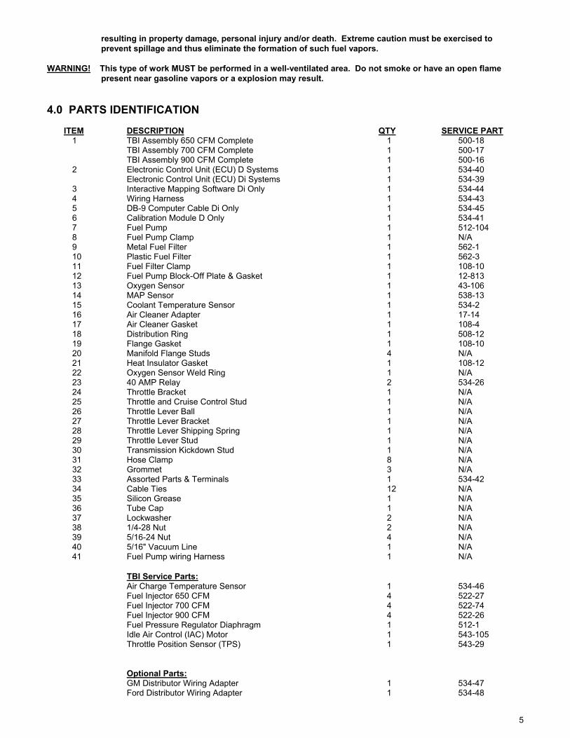
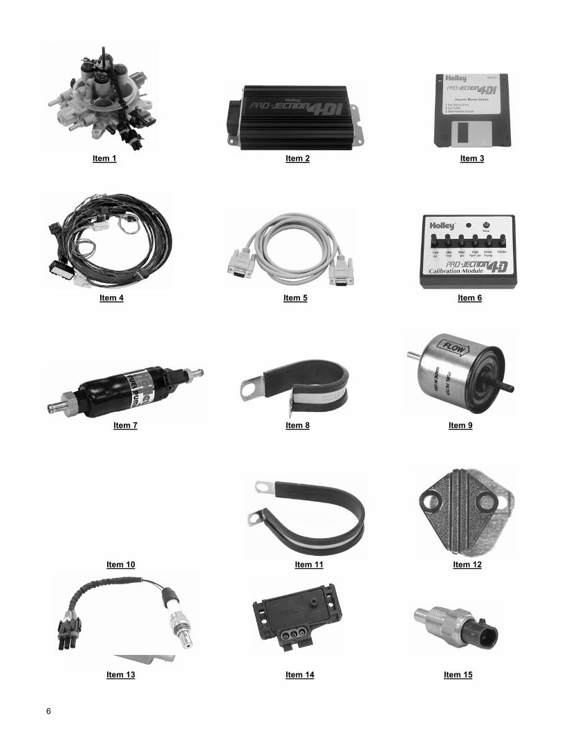
resulting in property damage, personal injury and/or death. Extreme caution must be exercised to prevent spillage and thus eliminate the formation of such fuel vapors. WARNING! This type of work MUST be performed in a well-ventilated area. Do not smoke or have an open flame present near gasoline vapors or a explosion may result. 4.0 PARTS IDENTIFICATION ITEM DESCRIPTION QTY SERVICE PART 1 TBI Assembly 650 CFM Complete 1 500-18 TBI Assembly 700 CFM Complete 1 500-17 TBI Assembly 900 CFM Complete 1 500-16 2 Electronic Control Unit (ECU) D Systems 1 534-40 Electronic Control Unit (ECU) Di Systems 1 534-39 3 Interactive Mapping Software Di Only 1 534-44 4 Wiring Harness 1 534-43 5 DB-9 Computer Cable Di Only 1 534-45 6 Calibration Module D Only 1 534-41 7 Fuel Pump 1 512-104 8 Fuel Pump Clamp 1 N/A 9 Metal Fuel Filter 1 562-1 10 Plastic Fuel Filter 1 562-3 11 Fuel Filter Clamp 1 108-10 12 Fuel Pump Block-Off Plate & Gasket 1 12-813 13 Oxygen Sensor 1 43-106 14 MAP Sensor 1 538-13 15 Coolant Temperature Sensor 1 534-2 16 Air Cleaner Adapter 1 17-14 17 Air Cleaner Gasket 1 108-4 18 Distribution Ring 1 508-12 19 Flange Gasket 1 108-10 20 Manifold Flange Studs 4 N/A 21 Heat Insulator Gasket 1 108-12 22 Oxygen Sensor Weld Ring 1 N/A 23 40 AMP Relay 2 534-26 24 Throttle Bracket 1 N/A 25 Throttle and Cruise Control Stud 1 N/A 26 Throttle Lever Ball 1 N/A 27 Throttle Lever Bracket 1 N/A 28 Throttle Lever Shipping Spring 1 N/A 29 Throttle Lever Stud 1 N/A 30 Transmission Kickdown Stud 1 N/A 31 Hose Clamp 8 N/A 32 Grommet 3 N/A 33 Assorted Parts & Terminals 1 534-42 34 Cable Ties 12 N/A 35 Silicon Grease 1 N/A 36 Tube Cap 1 N/A 37 Lockwasher 2 N/A 38 1/4-28 Nut 2 N/A 39 5/16-24 Nut 4 N/A 40 5/16" Vacuum Line 1 N/A 41 Fuel Pump wiring Harness 1 N/A TBI Service Parts: Air Charge Temperature Sensor 1 534-46 Fuel Injector 650 CFM 4 522-27 Fuel Injector 700 CFM 4 522-74 Fuel Injector 900 CFM 4 522-26 Fuel Pressure Regulator Diaphragm 1 512-1 Idle Air Control (IAC) Motor 1 543-105 Throttle Position Sensor (TPS) 1 543-29 Optional Parts: GM Distributor Wiring Adapter 1 534-47 Ford Distributor Wiring Adapter 1 534-48
6
Item 1 Item 2 Item 3
Item 4 Item 5 Item 6
Item 7 Item 8 Item 9
Item 10 Item 11 Item 12
Item 13 Item 14 Item 15

7
Item 16 Item 17 Item 18
Item 19 Item 20 Item 21
Item 22 Item 23 Item 24
Item 25 Item 26 Item 27
Item 28 Item 29 Item 30

8
Item 31 Item 32 Item 33
Item 34 Item 35 Item 36
Item 37 Item 38 Item 39
Item 40 Item 41 5.0 ADDITIONAL ITEMS REQUIRED FOR INSTALLATION • 3/8" fuel hose (must meet SAE J30) • 5/16" fuel hose (must meet SAE J30) • 5/16" steel fuel line (must meet SAE J526) • 0-30 psi fuel gauge • Tee fitting for fuel gauge In addition to the above list, the engine must be equipped with a four barrel intake manifold and the vehicle must be in good operating condition.
9
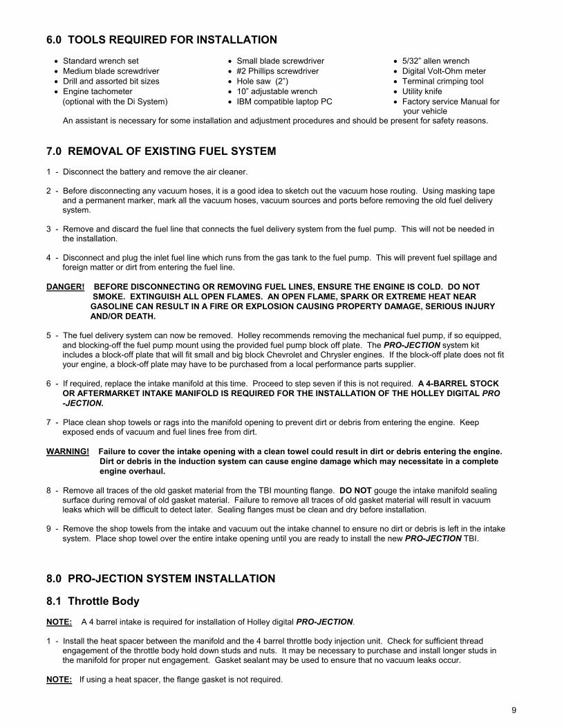
6.0 TOOLS REQUIRED FOR INSTALLATION • Standard wrench set • Small blade screwdriver • 5/32” allen wrench • Medium blade screwdriver • #2 Phillips screwdriver • Digital Volt-Ohm meter • Drill and assorted bit sizes • Hole saw (2”) • Terminal crimping tool • Engine tachometer • 10” adjustable wrench • Utility knife (optional with the Di System) • IBM compatible laptop PC • Factory service Manual for your vehicle An assistant is necessary for some installation and adjustment procedures and should be present for safety reasons. 7.0 REMOVAL OF EXISTING FUEL SYSTEM 1 - Disconnect the battery and remove the air cleaner. 2 - Before disconnecting any vacuum hoses, it is a good idea to sketch out the vacuum hose routing. Using masking tape and a permanent marker, mark all the vacuum hoses, vacuum sources and ports before removing the old fuel delivery system. 3 - Remove and discard the fuel line that connects the fuel delivery system from the fuel pump. This will not be needed in the installation. 4 - Disconnect and plug the inlet fuel line which runs from the gas tank to the fuel pump. This will prevent fuel spillage and foreign matter or dirt from entering the fuel line. DANGER! BEFORE DISCONNECTING OR REMOVING FUEL LINES, ENSURE THE ENGINE IS COLD. DO NOT SMOKE. EXTINGUISH ALL OPEN FLAMES. AN OPEN FLAME, SPARK OR EXTREME HEAT NEAR GASOLINE CAN RESULT IN A FIRE OR EXPLOSION CAUSING PROPERTY DAMAGE, SERIOUS INJURY AND/OR DEATH. 5 - The fuel delivery system can now be removed. Holley recommends removing the mechanical fuel pump, if so equipped, and blocking-off the fuel pump mount using the provided fuel pump block off plate. The PRO-JECTION system kit includes a block-off plate that will fit small and big block Chevrolet and Chrysler engines. If the block-off plate does not fit your engine, a block-off plate may have to be purchased from a local performance parts supplier. 6 - If required, replace the intake manifold at this time. Proceed to step seven if this is not required. A 4-BARREL STOCK OR AFTERMARKET INTAKE MANIFOLD IS REQUIRED FOR THE INSTALLATION OF THE HOLLEY DIGITAL PRO -JECTION. 7 - Place clean shop towels or rags into the manifold opening to prevent dirt or debris from entering the engine. Keep exposed ends of vacuum and fuel lines free from dirt. WARNING! Failure to cover the intake opening with a clean towel could result in dirt or debris entering the engine. Dirt or debris in the induction system can cause engine damage which may necessitate in a complete engine overhaul. 8 - Remove all traces of the old gasket material from the TBI mounting flange. DO NOT gouge the intake manifold sealing surface during removal of old gasket material. Failure to remove all traces of old gasket material will result in vacuum leaks which will be difficult to detect later. Sealing flanges must be clean and dry before installation. 9 - Remove the shop towels from the intake and vacuum out the intake channel to ensure no dirt or debris is left in the intake system. Place shop towel over the entire intake opening until you are ready to install the new PRO-JECTION TBI. 8.0 PRO-JECTION SYSTEM INSTALLATION 8.1 Throttle Body NOTE: A 4 barrel intake is required for installation of Holley digital PRO-JECTION. 1 - Install the heat spacer between the manifold and the 4 barrel throttle body injection unit. Check for sufficient thread engagement of the throttle body hold down studs and nuts. It may be necessary to purchase and install longer studs in the manifold for proper nut engagement. Gasket sealant may be used to ensure that no vacuum leaks occur. NOTE: If using a heat spacer, the flange gasket is not required.
10
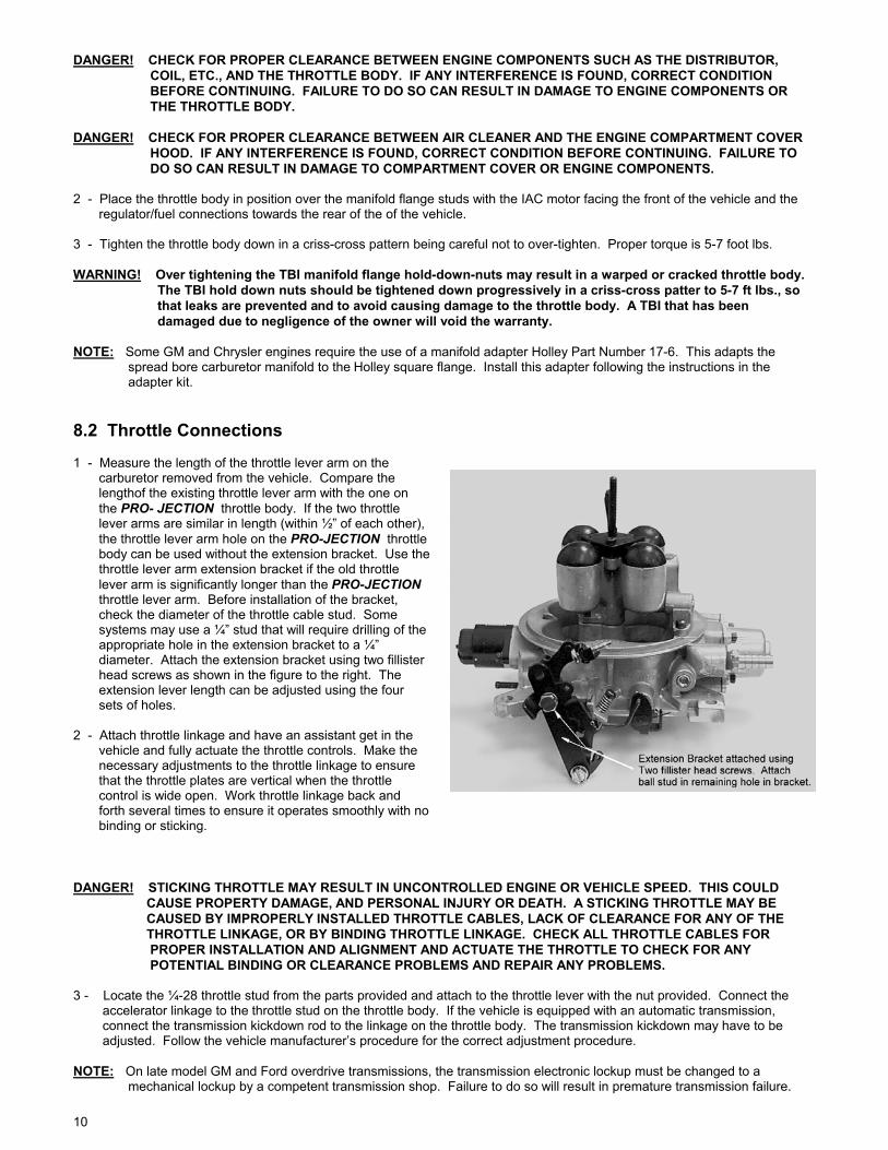
DANGER! CHECK FOR PROPER CLEARANCE BETWEEN ENGINE COMPONENTS SUCH AS THE DISTRIBUTOR, COIL, ETC., AND THE THROTTLE BODY. IF ANY INTERFERENCE IS FOUND, CORRECT CONDITION BEFORE CONTINUING. FAILURE TO DO SO CAN RESULT IN DAMAGE TO ENGINE COMPONENTS OR THE THROTTLE BODY. DANGER! CHECK FOR PROPER CLEARANCE BETWEEN AIR CLEANER AND THE ENGINE COMPARTMENT COVER HOOD. IF ANY INTERFERENCE IS FOUND, CORRECT CONDITION BEFORE CONTINUING. FAILURE TO DO SO CAN RESULT IN DAMAGE TO COMPARTMENT COVER OR ENGINE COMPONENTS. 2 - Place the throttle body in position over the manifold flange studs with the IAC motor facing the front of the vehicle and the regulator/fuel connections towards the rear of the of the vehicle. 3 - Tighten the throttle body down in a criss-cross pattern being careful not to over-tighten. Proper torque is 5-7 foot lbs. WARNING! Over tightening the TBI manifold flange hold-down-nuts may result in a warped or cracked throttle body. The TBI hold down nuts should be tightened down progressively in a criss-cross patter to 5-7 ft lbs., so that leaks are prevented and to avoid causing damage to the throttle body. A TBI that has been damaged due to negligence of the owner will void the warranty. NOTE: Some GM and Chrysler engines require the use of a manifold adapter Holley Part Number 17-6. This adapts the spread bore carburetor manifold to the Holley square flange. Install this adapter following the instructions in the adapter kit. 8.2 Throttle Connections 1 - Measure the length of the throttle lever arm on the carburetor removed from the vehicle. Compare the lengthof the existing throttle lever arm with the one on the PRO- JECTION throttle body. If the two throttle lever arms are similar in length (within ½” of each other), the throttle lever arm hole on the PRO-JECTION throttle body can be used without the extension bracket. Use the throttle lever arm extension bracket if the old throttle lever arm is significantly longer than the PRO-JECTION throttle lever arm. Before installation of the bracket, check the diameter of the throttle cable stud. Some systems may use a ¼” stud that will require drilling of the appropriate hole in the extension bracket to a ¼” diameter. Attach the extension bracket using two fillister head screws as shown in the figure to the right. The extension lever length can be adjusted using the four sets of holes. 2 - Attach throttle linkage and have an assistant get in the vehicle and fully actuate the throttle controls. Make the necessary adjustments to the throttle linkage to ensure that the throttle plates are vertical when the throttle control is wide open. Work throttle linkage back and forth several times to ensure it operates smoothly with no binding or sticking. DANGER! STICKING THROTTLE MAY RESULT IN UNCONTROLLED ENGINE OR VEHICLE SPEED. THIS COULD CAUSE PROPERTY DAMAGE, AND PERSONAL INJURY OR DEATH. A STICKING THROTTLE MAY BE CAUSED BY IMPROPERLY INSTALLED THROTTLE CABLES, LACK OF CLEARANCE FOR ANY OF THE THROTTLE LINKAGE, OR BY BINDING THROTTLE LINKAGE. CHECK ALL THROTTLE CABLES FOR PROPER INSTALLATION AND ALIGNMENT AND ACTUATE THE THROTTLE TO CHECK FOR ANY POTENTIAL BINDING OR CLEARANCE PROBLEMS AND REPAIR ANY PROBLEMS. 3 - Locate the ¼-28 throttle stud from the parts provided and attach to the throttle lever with the nut provided. Connect the accelerator linkage to the throttle stud on the throttle body. If the vehicle is equipped with an automatic transmission, connect the transmission kickdown rod to the linkage on the throttle body. The transmission kickdown may have to be adjusted. Follow the vehicle manufacturer’s procedure for the correct adjustment procedure. NOTE: On late model GM and Ford overdrive transmissions, the transmission electronic lockup must be changed to a mechanical lockup by a competent transmission shop. Failure to do so will result in premature transmission failure.
11
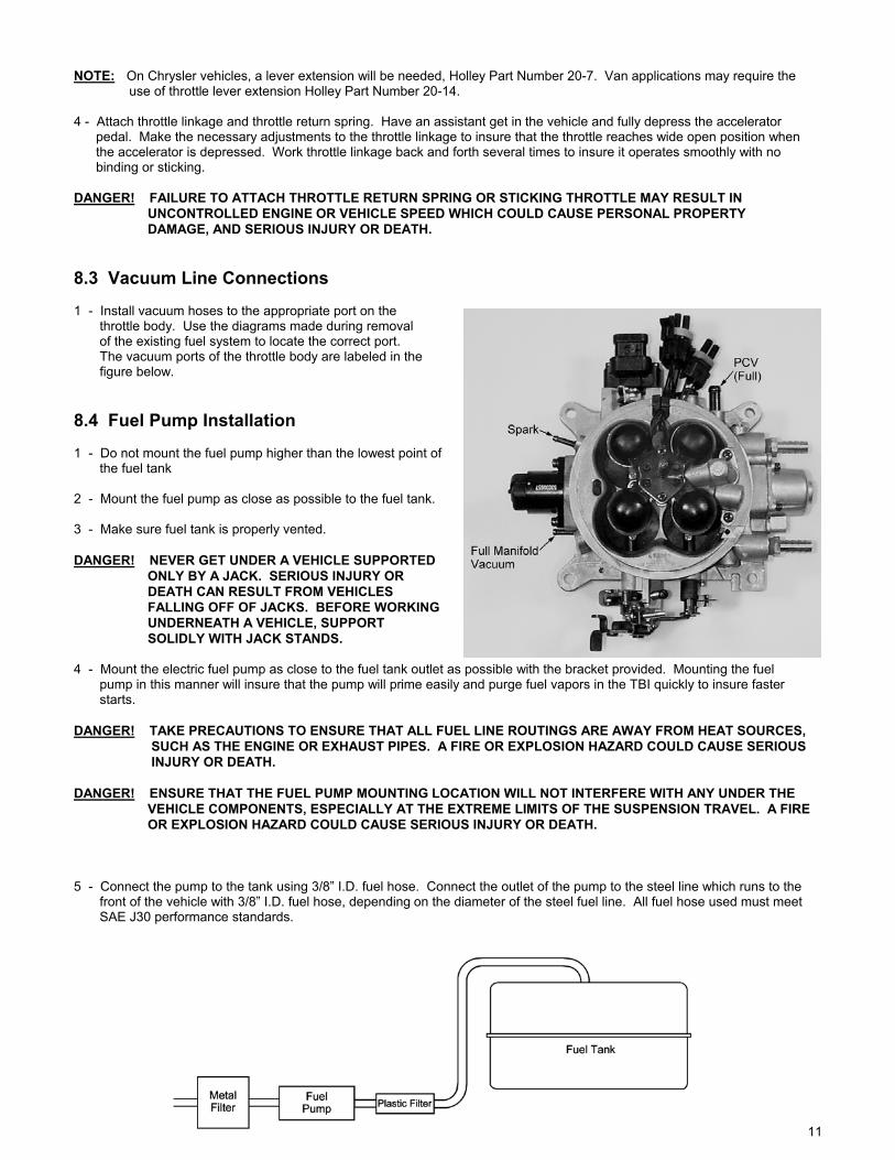
NOTE: On Chrysler vehicles, a lever extension will be needed, Holley Part Number 20-7. Van applications may require the use of throttle lever extension Holley Part Number 20-14. 4 - Attach throttle linkage and throttle return spring. Have an assistant get in the vehicle and fully depress the accelerator pedal. Make the necessary adjustments to the throttle linkage to insure that the throttle reaches wide open position when the accelerator is depressed. Work throttle linkage back and forth several times to insure it operates smoothly with no binding or sticking. DANGER! FAILURE TO ATTACH THROTTLE RETURN SPRING OR STICKING THROTTLE MAY RESULT IN UNCONTROLLED ENGINE OR VEHICLE SPEED WHICH COULD CAUSE PERSONAL PROPERTY DAMAGE, AND SERIOUS INJURY OR DEATH. 8.3 Vacuum Line Connections 1 - Install vacuum hoses to the appropriate port on the throttle body. Use the diagrams made during removal of the existing fuel system to locate the correct port. The vacuum ports of the throttle body are labeled in the figure below. 8.4 Fuel Pump Installation 1 - Do not mount the fuel pump higher than the lowest point of the fuel tank 2 - Mount the fuel pump as close as possible to the fuel tank. 3 - Make sure fuel tank is properly vented. DANGER! NEVER GET UNDER A VEHICLE SUPPORTED ONLY BY A JACK. SERIOUS INJURY OR DEATH CAN RESULT FROM VEHICLES FALLING OFF OF JACKS. BEFORE WORKING UNDERNEATH A VEHICLE, SUPPORT SOLIDLY WITH JACK STANDS. 4 - Mount the electric fuel pump as close to the fuel tank outlet as possible with the bracket provided. Mounting the fuel pump in this manner will insure that the pump will prime easily and purge fuel vapors in the TBI quickly to insure faster starts. DANGER! TAKE PRECAUTIONS TO ENSURE THAT ALL FUEL LINE ROUTINGS ARE AWAY FROM HEAT SOURCES, SUCH AS THE ENGINE OR EXHAUST PIPES. A FIRE OR EXPLOSION HAZARD COULD CAUSE SERIOUS INJURY OR DEATH. DANGER! ENSURE THAT THE FUEL PUMP MOUNTING LOCATION WILL NOT INTERFERE WITH ANY UNDER THE VEHICLE COMPONENTS, ESPECIALLY AT THE EXTREME LIMITS OF THE SUSPENSION TRAVEL. A FIRE OR EXPLOSION HAZARD COULD CAUSE SERIOUS INJURY OR DEATH. 5 - Connect the pump to the tank using 3/8” I.D. fuel hose. Connect the outlet of the pump to the steel line which runs to the front of the vehicle with 3/8” I.D. fuel hose, depending on the diameter of the steel fuel line. All fuel hose used must meet SAE J30 performance standards.
12
DANGER! FAILURE TO USE FUEL HOSE THAT MEETS SAE J30 STANDARDS COULD RESULT IN FUEL LEAKS. A FUEL LEAK MAY RESULT IN A FIRE OR EXPLOSION HAZARD WHICH COULD CAUSE SERIOUS INJURY OR DEATH. 6 - If using existing fuel lines, inspect and replace any hose, clamps, or fuel line showing any sign of aging. If you are not using existing fuel lines, you will need a fuel line routed to the engine compartment and DIGITAL PROJECTION throttle body. Use a 3/8” steel fuel line available at any auto parts store. All steel fuel line must meet SAE J526 standards. DANGER! FAILURE TO USE STEEL FUEL LINE THAT MEETS SAE J526 STANDARDS COULD RESULT IN FUEL LEAKS. A FUEL LEAK MAY RESULT IN A FIRE OR EXPLOSION HAZARD WHICH COULD CAUSE SERIOUS INJURY OR DEATH. DANGER! TAKE PRECAUTIONS TO ENSURE THAT ALL FUEL LINE ROUTINGS ARE AWAY FROM HEAT SOURCES, SUCH AS THE ENGINE OR EXHAUST PIPES. A FIRE OR EXPLOSION HAZARD COULD CAUSE SERIOUS INJURY OR DEATH. DANGER! RIGID FUEL LINE TUBING SHOULD BE USED FOR UNDER VEHICLE RUNS, SUCH AS ALONG VEHICLE FRAME RAILS OR UNDER FLOOR PANS. FAILURE TO DO SO IS A POTENTIAL FIRE OR EXPLOSION HAZARD WHICH COULD CAUSE SERIOUS INJURY OR DEATH. 7 - Anchor all fuel lines securely to solid chassis members at 1 ½ foot intervals using rubber coated steel clamps. Use of only approved steel fuel line tubing will afford maximum fuel line protection against road hazards and premature wearing due to flexing, temperature extremes, road salt, weather, etc. 8.5 Dual Tank Installation The following are special instructions for vehicles equipped with dual fuel tanks. Holley DIGITAL PROJECTION fuel injection systems require a fuel return line and in dual tank applications, the fuel must be returned to the tank from which it was drawn. The items listed below are recommended to properly install your DIGITAL PROJECTION system on a dual tank vehicle. A separate fuel pump and filter for each tank will be necessary. Holley offers these items in a kit, part number 534-37. Item Part Number Selection valve 42-149 Valve Connector 42-203 Toggle switch 34-576 Relay 534-26 Fuel pump 512-103 10 amp in line fuse - Fuel filter 562-3 This is a recommended list and except for the fuel pump, equivalent parts may be substituted. In addition, fuel hose, clamps, 18 gauge wire, and assorted terminals will be needed. The selection valve recommended switches tanks by reversing the polarity of the “D” and “E” terminals. Many trucks equipped with dual tanks already have this type of selection valve along with the associated hardware. 1 - Mount the selection valve in a protected location close to the existing fuel lines and near the fuel tanks. Position the valve so the side with the four hose nipples points toward the fuel tanks. Mount the fuel pumps along the fuel supply lines and next to each fuel tank. Fuel filters (Holley Part Number 562-3) MUST be located between each tank and pump. Make sure pump inlets point toward the tanks. (See FIGURE on next page). Warning! The supply and return hoses from the same tank must be connected next to each other on the selection valve.

13
2 - All hoses should be secured with worm gear type clamps. Avoid sharp bends in the fuel lines. 3 - Mount the double position, double throw toggle switch along with the relay under the dash if the vehicle is not already equipped with this type switch. Connect the electrical wiring as shown in the FIGURE below. NOTE: All wiring should be 18 gauge or heavier automotive wire that meets SAE J1560 standards. Wire the toggle switch as illustrated with one pair of terminals wired to ground and the other pair to a 12 volt power source through the relay and a 10 amp fuse. The terminals on the plug-in connector are labeled A - F and should be wired to the following items: A Fuel sending unit, tank #1 B Fuel gauge at dash C Fuel sending unit, tank #2 D Fuel pump #2 (+12v) and switch E Fuel pump #1 (+12v) and switch F Not used 4 - Plug the connector into the selection valve. Double check all fuel and electrical connections to be sure they are installed properly. Electrical connections should be insulated and sealed to prevent arcing and corrosion. Check the operation of the selection valve when the DIGITAL PROJECTION installation is complete.
8.6 Fuel Pump Filter A filter MUST be installed between the fuel tank and the fuel pump inlet. The purpose of this filter is to protect the fuel pump from particles of dirt or other foreign material. The filter should be installed with the arrow on the filter pointing in the direction of the fuel flow. Secure the ends of the fuel lines with hose clamps. 8.7 Throttle Body Fuel Filter
14
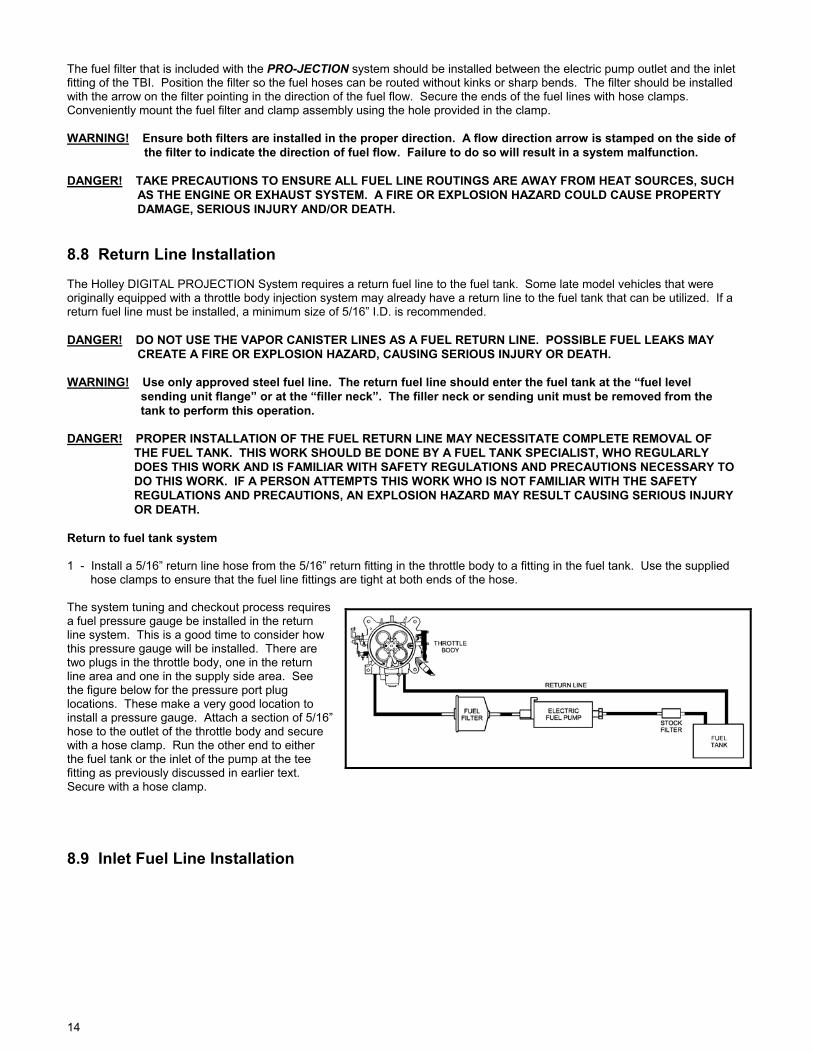
The fuel filter that is included with the PRO-JECTION system should be installed between the electric pump outlet and the inlet fitting of the TBI. Position the filter so the fuel hoses can be routed without kinks or sharp bends. The filter should be installed with the arrow on the filter pointing in the direction of the fuel flow. Secure the ends of the fuel lines with hose clamps. Conveniently mount the fuel filter and clamp assembly using the hole provided in the clamp. WARNING! Ensure both filters are installed in the proper direction. A flow direction arrow is stamped on the side of the filter to indicate the direction of fuel flow. Failure to do so will result in a system malfunction. DANGER! TAKE PRECAUTIONS TO ENSURE ALL FUEL LINE ROUTINGS ARE AWAY FROM HEAT SOURCES, SUCH AS THE ENGINE OR EXHAUST SYSTEM. A FIRE OR EXPLOSION HAZARD COULD CAUSE PROPERTY DAMAGE, SERIOUS INJURY AND/OR DEATH. 8.8 Return Line Installation The Holley DIGITAL PROJECTION System requires a return fuel line to the fuel tank. Some late model vehicles that were originally equipped with a throttle body injection system may already have a return line to the fuel tank that can be utilized. If a return fuel line must be installed, a minimum size of 5/16” I.D. is recommended. DANGER! DO NOT USE THE VAPOR CANISTER LINES AS A FUEL RETURN LINE. POSSIBLE FUEL LEAKS MAY CREATE A FIRE OR EXPLOSION HAZARD, CAUSING SERIOUS INJURY OR DEATH. WARNING! Use only approved steel fuel line. The return fuel line should enter the fuel tank at the “fuel level sending unit flange” or at the “filler neck”. The filler neck or sending unit must be removed from the tank to perform this operation. DANGER! PROPER INSTALLATION OF THE FUEL RETURN LINE MAY NECESSITATE COMPLETE REMOVAL OF THE FUEL TANK. THIS WORK SHOULD BE DONE BY A FUEL TANK SPECIALIST, WHO REGULARLY DOES THIS WORK AND IS FAMILIAR WITH SAFETY REGULATIONS AND PRECAUTIONS NECESSARY TO DO THIS WORK. IF A PERSON ATTEMPTS THIS WORK WHO IS NOT FAMILIAR WITH THE SAFETY REGULATIONS AND PRECAUTIONS, AN EXPLOSION HAZARD MAY RESULT CAUSING SERIOUS INJURY OR DEATH. Return to fuel tank system 1 - Install a 5/16” return line hose from the 5/16” return fitting in the throttle body to a fitting in the fuel tank. Use the supplied hose clamps to ensure that the fuel line fittings are tight at both ends of the hose. The system tuning and checkout process requires a fuel pressure gauge be installed in the return line system. This is a good time to consider how this pressure gauge will be installed. There are two plugs in the throttle body, one in the return line area and one in the supply side area. See the figure below for the pressure port plug locations. These make a very good location to install a pressure gauge. Attach a section of 5/16” hose to the outlet of the throttle body and secure with a hose clamp. Run the other end to either the fuel tank or the inlet of the pump at the tee fitting as previously discussed in earlier text. Secure with a hose clamp. 8.9 Inlet Fuel Line Installation

15
1 - Route a 3/8” hose from the PRO-JECTION electric fuel pump outlet to the metal fuel filter inlet. Then install a 3/8” hose from the filter outlet to the TBI inlet. The fuel line connection on the left side of the throttle body (or linkage side) is the connection for the supply line. The remaining fuel line connection on the TPS side of the throttle body is for the return fuel line. Properly secure all hoses with hose clamps. 2 - If you plan to install fuel pressure gauges, do so at this time. If you do not plan to install fuel pressure gauges, a temporary gauge will have to be installed on the return fuel line. To install a temporary gauge to the return fuel line, a short length of 3/8” I.D. fuel hose, a tee fitting, and a 0 - 30 psig fuel gauge are needed. Screw the gauge into the center of the tee fitting. Attach the short length of hose to one end of the fitting. Attach the free end of this hose to the throttle body fuel return fitting. Attach the return fuel hose to the remaining side of the tee fitting. WARNING! Ensure there is a fuel filter between the fuel tank and pump(s). If one must be added, use Holley replacement filters only. 8.10 Oxygen Sensor Installation 8.10.1 Oxygen Sensor Function, Theory, and Use Both the PRO-JECTION D and Di systems allow the user to operate their engine in a closed loop fuel management mode using the oxygen sensor. The oxygen sensor monitors the exhaust gases and outputs a voltage that corresponds to the fuel/air mixture. The range of voltage output from the oxygen sensor is 0.0 to 1.0 volts. A lean fuel/air mixture gives a lower oxygen sensor output voltage while a rich fuel/air mixture gives a higher oxygen sensor output voltage. The stoichiometric or chemically perfect fuel/air mixture gives an oxygen sensor output of approximately 0.5 volts. The engine ECU reads this output from the oxygen sensor and adjusts the fuel delivery to maintain a stoichiometric fuel/air mixture. Most automobiles, both currently and for the past 20 years, are using oxygen sensors to monitor the engine fuel/air mixture. This is done primarily to improve engine emissions. It also gives the advantage of maintaining a stoichiometric fuel/air mixture under varied operating conditions giving generally better engine performance and fuel economy. Holley includes oxygen sensor feedback capability with the PRO-JECTION system and recommends the user to use the oxygen sensor. For most user applications, better performance and fuel economy will be obtained by using the oxygen sensor. In addition, the oxygen sensor can make the tuning process with a Di system much easier since the user can monitor the ECU functions as it adjusts the fuel to meet a stoichiometric fuel/air mixture. The user should read paragraph 4 of section 11.3 on engine configuration related concerns to help them determine whether an oxygen sensor should be used for their engine installation. 8.10.2 Oxygen Sensor Mounting Procedure NOTE: The oxygen sensor boss should be installed by someone with experience welding exhaust systems. Any competent exhaust shop is able to perform this task at minimum cost. WARNING! Use only unleaded fuel when operating an oxygen sensor. Use of leaded fuels will destroy the oxygen sensor and will result in incorrect exhaust gas oxygen-content readings. WARNING! Use of some RTV silicone sealers will destroy the oxygen sensor used with this product. Ensure the RTV silicone sealant you use is compatible with oxygen sensor vehicles. This information should be found on the oxygen sensor package. 1 - Locate a position for the oxygen sensor as close to the engine as possible. If your vehicle has catalytic converters, the oxygen sensor MUST be located between the engine and the catalytic convertors. Good locations are in the drop pipe, or in the “”Y” pipe on single exhaust systems. Pick a location that allows easy installation of the oxygen sensor, but will
16
protect the sensor from road hazards. 2 - Drill a 7/8” hole in the location picked for the sensor. Weld the threaded boss into the 7/8” hole. Weld all the way around the boss to insure a leak proof connection. Install the oxygen sensor into the threaded boss and tighten securely. It is a good idea to add anti-seize to the threads to aid in removal. 3 - On vehicles equipped with an AIR pump, the oxygen sensor must be mounted before the AIR injection into the exhaust, or the AIR pump must be disconnected. Holley recommends that if the AIR is injected into both exhaust manifolds, mount the oxygen sensor into the pipe immediately after the exhaust manifold. Disconnect the AIR pump tube from the exhaust manifold and plug both ends. Check with local ordinances for the legality of this procedure in your area. WARNING! Failure to disconnect the AIR pump or locating the oxygen sensor downstream from AIR injection will result in an extremely rich mixture which could cause drivability problems and severe engine damage. 8.11 Electronic Control Unit (ECU) Mounting 1 - Pick a suitable location outside of the engine compartment but in a dry area for mounting of the Electronic Control Unit (ECU). Check for sufficient length of the wiring harness and clearance for connectors before mounting ECU. WARNING! Do not mount the ECU in the engine compartment or in an area exposed to the elements of weather or areas that can get wet during use. The ECU is not designed for an environment with significant amounts of heat or moisture. Premature failure of the ECU will result. WARNING! Before drilling, check both sides of the bulkhead for possible interference with electrical systems, etc. Failure to do so can result in damage to one of the vehicle systems. 2 - Drill 4 pilot holes using the ECU as a template. 3 - Use the 4 short self tapping screws provided to securely mount the ECU. 8.12 Engine Wiring Harness 1 - At a location near the ECU mounting, pick a suitable location on the engine compartment bulkhead/firewall for the wiring harness to pass through. A 2” diameter hole will be required for the wiring harness. Check both sides of the bulkhead/firewall for interference. WARNING! Before drilling, check both sides of the bulkhead/firewall for possible interference with electrical systems, etc. Failure to do so can result in damage to one of the vehicle systems. 2 - Use a 2” hole saw, available at any hardware store, or a punch out tool to cut through the bulkhead/firewall as necessary. 3 - Feed the wiring harness from the location of the ECU to the engine compartment. Check to ensure sufficient length of harness is available for attaching to the ECU. 4 - Slit the 2” grommet provided and position around the wiring harness. Slip the grommet into the 2” hole to prevent the wiring harness from chaffing. A light application of WD-40 on the grommet will ease the installation. 5 - Connect the wiring harness to the ECU. Push the plug into the ECU until the lock snaps into position. 8.13 Coolant Temperature Sensor Drain the engine radiator until the coolant level is below the coolant temperature sensor port on the intake manifold. Install the temperature sensor in a water passage of the intake manifold. Most intake manifolds have a plug that can be removed for installation of a temperature sensor. In addition, some cylinder heads have a plug that can be removed for installation of a temperature sensor. Do not install the sensor in the thermostat housing. Do not use any pipe sealer on the threads, which may degrade or reduce the ground connection of the sensor. Torque the sensor to 15 foot pounds. Remember to refill the cooling system to capacity. 8.14 Manifold Absolute Pressure (MAP) Sensor 1 - Locate a position on the bulkhead/firewall of the engine compartment for installation of the MAP sensor.
17
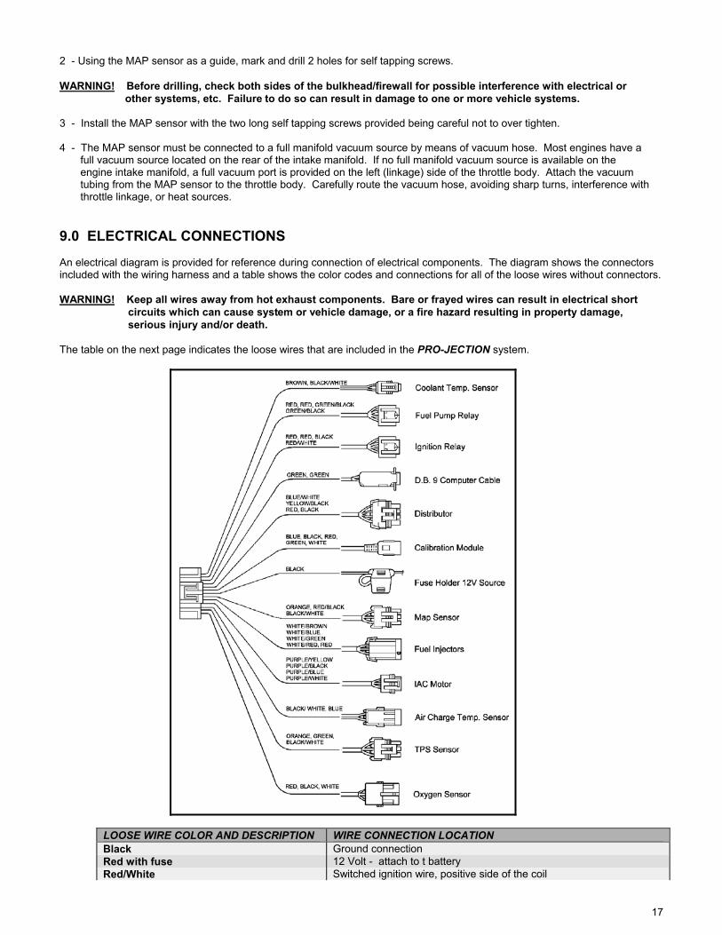
2 - Using the MAP sensor as a guide, mark and drill 2 holes for self tapping screws. WARNING! Before drilling, check both sides of the bulkhead/firewall for possible interference with electrical or other systems, etc. Failure to do so can result in damage to one or more vehicle systems. 3 - Install the MAP sensor with the two long self tapping screws provided being careful not to over tighten. 4 - The MAP sensor must be connected to a full manifold vacuum source by means of vacuum hose. Most engines have a full vacuum source located on the rear of the intake manifold. If no full manifold vacuum source is available on the engine intake manifold, a full vacuum port is provided on the left (linkage) side of the throttle body. Attach the vacuum tubing from the MAP sensor to the throttle body. Carefully route the vacuum hose, avoiding sharp turns, interference with throttle linkage, or heat sources. 9.0 ELECTRICAL CONNECTIONS An electrical diagram is provided for reference during connection of electrical components. The diagram shows the connectors included with the wiring harness and a table shows the color codes and connections for all of the loose wires without connectors. WARNING! Keep all wires away from hot exhaust components. Bare or frayed wires can result in electrical short circuits which can cause system or vehicle damage, or a fire hazard resulting in property damage, serious injury and/or death. The table on the next page indicates the loose wires that are included in the PRO-JECTION system.
LOOSE WIRE COLOR AND DESCRIPTION WIRE CONNECTION LOCATION Black Ground connection Red with fuse 12 Volt - attach to t battery Red/White Switched ignition wire, positive side of the coil
18
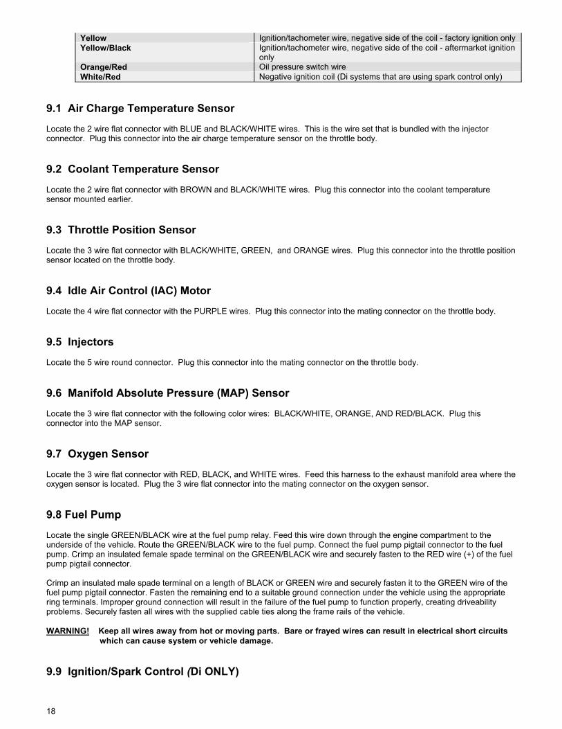
Yellow Ignition/tachometer wire, negative side of the coil - factory ignition only Yellow/Black Ignition/tachometer wire, negative side of the coil - aftermarket ignition
only Orange/Red Oil pressure switch wire White/Red Negative ignition coil (Di systems that are using spark control only)
9.1 Air Charge Temperature Sensor Locate the 2 wire flat connector with BLUE and BLACK/WHITE wires. This is the wire set that is bundled with the injector connector. Plug this connector into the air charge temperature sensor on the throttle body. 9.2 Coolant Temperature Sensor Locate the 2 wire flat connector with BROWN and BLACK/WHITE wires. Plug this connector into the coolant temperature sensor mounted earlier. 9.3 Throttle Position Sensor Locate the 3 wire flat connector with BLACK/WHITE, GREEN, and ORANGE wires. Plug this connector into the throttle position sensor located on the throttle body. 9.4 Idle Air Control (IAC) Motor Locate the 4 wire flat connector with the PURPLE wires. Plug this connector into the mating connector on the throttle body. 9.5 Injectors Locate the 5 wire round connector. Plug this connector into the mating connector on the throttle body. 9.6 Manifold Absolute Pressure (MAP) Sensor Locate the 3 wire flat connector with the following color wires: BLACK/WHITE, ORANGE, AND RED/BLACK. Plug this connector into the MAP sensor. 9.7 Oxygen Sensor Locate the 3 wire flat connector with RED, BLACK, and WHITE wires. Feed this harness to the exhaust manifold area where the oxygen sensor is located. Plug the 3 wire flat connector into the mating connector on the oxygen sensor. 9.8 Fuel Pump Locate the single GREEN/BLACK wire at the fuel pump relay. Feed this wire down through the engine compartment to the underside of the vehicle. Route the GREEN/BLACK wire to the fuel pump. Connect the fuel pump pigtail connector to the fuel pump. Crimp an insulated female spade terminal on the GREEN/BLACK wire and securely fasten to the RED wire (+) of the fuel pump pigtail connector. Crimp an insulated male spade terminal on a length of BLACK or GREEN wire and securely fasten it to the GREEN wire of the fuel pump pigtail connector. Fasten the remaining end to a suitable ground connection under the vehicle using the appropriate ring terminals. Improper ground connection will result in the failure of the fuel pump to function properly, creating driveability problems. Securely fasten all wires with the supplied cable ties along the frame rails of the vehicle. WARNING! Keep all wires away from hot or moving parts. Bare or frayed wires can result in electrical short circuits which can cause system or vehicle damage. 9.9 Ignition/Spark Control (Di ONLY)

19
Attach the 4 wire flat connector with BLUE/WHITE, YELLOW/BLACK, RED and BLACK wires to the GM 7-wire distributor. If the 4 wire terminal is too large to connect with your distributor, use Holley part number 534-47, GM Distributor Wiring Adapter. Plug this adapter into your distributor and plug the 4-wire connector from the wiring harness into the adapter. If you are using a Ford non-signature TBI distributor, use Holley part number 534-48, Ford Distributor Wiring Adapter. Plug this adapter into your distributor and plug the 4-wire connector from the wiring harness into the adapter. Connect the WHITE/RED wire using the enclosed ring terminal to the (-) side of the ignition coil. 9.10 Fuel Pump and System Power Relays 1 - Two relays are provided in the kit. One relay is for the ECU system power and the other controls the fuel pump. Locate a suitable position on or near the engine compartment. Make sure that the wiring harness lengths will work with the location chosen for the relays. 2 - Mark the location of the mounting holes. Drill two holes for mounting the relays. WARNING! Before drilling, check both sides of the bulkhead for possible interference with electrical systems, etc. Failure to do so can result in damage to one of the boat systems. 3 - Mount the relays with the remaining 2 short self tapping screws provided, being careful not to over tighten. 4 - Locate the power relay connector and the fuel pump relay connector on the wiring harness. The connectors are rectangular in shape and identical in appearance. Connect the connector plugs to the relays. 9.11 System Power Using the assorted connector package and a terminal crimping tool, assemble and connect the wiring as follows: A - BLACK wire (ground) - Install suitable connector and attach to a good ground. Make sure that the grounds are very good. Poor grounds cause many electrical system problems. B - RED wire with fuse (12 volt) - Install suitable connector and attach to battery. Make sure that 12 volt connections make good connection and use good quality connectors. Voltage drop due to poor connection can cause electrical system problems. C - RED/WHITE (switched ignition) - Install suitable connector and attach to (+) terminal of coil, or a switched ignition 12 volt power source. NOTE: If you use a switched ignition power source, make sure the power source remains energized when the key is in the crank position. 9.12 Tachometer/Ignition A - YELLOW wire (ignition) - For D systems only, install a suitable terminal to the single yellow wire in the harness and attach to the (-) side of the ignition coil. Do not connect the yellow/black wire. NOTE: For Di systems using spark control, do not connect the yellow wire. B - YELLOW/BLACK wire (ignition) - For aftermarket ignition systems only, install a suitable terminal to the yellow/black wire in the harness and attach to the (-) side of the ignition coil. Do not connect the yellow wire. NOTE: PRO-JECTION D systems will require a tachometer signal amplifier to work properly with most aftermarket ignition systems. NOTE: If you are using an aftermarket ignition, connect the YELLOW/BLACK wire from the distributor connector to the Ignition system’s tach output. Do not connect the single YELLOW wire. 9.13 Oil Pressure Switch On engines with a single wire oil pressure switch, connect the ORANGE/RED wire to the single oil pressure switch wire. This will not allow the engine speed to go above 2500 RPM in the event of an oil pressure problem. The vehicle can be moved slowly to a safe location. NOTE: This feature will not work with vehicles equipped with an oil pressure gauge. An oil pressure switch can be
20
purchased and installed in the oil circuit should the user desire this feature. 10.0 MECHANICAL CHECKOUT BEFORE STARTING ENGINE Before starting engine, review and check off the following items:
Are electrical connections correct? Are all fuel lines hooked up and correct? Is throttle linkage hooked up? Have fuel lines been leak checked? Are all vacuum hoses connected? Are all sensors installed and hooked up properly?
WARNING! For engines originally equipped with spark control, spark timing will not function with the PRO-JECTION D unit. An original equipment or aftermarket distributor with mechanical advance must be installed. Failure to do so will result in engine damage. 1 - Reconnect the battery. 2 - Install fuse in the fuse holder on the wiring harness. Before attempting to start the engine, perform the following to ensure that the system is properly connected: 3 - While listening carefully, turn the key to the RUN position. The fuel pump will turn on and run for a few seconds before being shut off by the ECU. This shutoff occurs when the key is in the run position and the ECU does not receive any engine speed signal. At the first startup of the system after installation when the fuel system is dry, the fuel pump may need to run longer than a few seconds. This may require additional cranking time to get fuel to the fuel injectors. A fuel pressure gauge in the fuel supply line is an excellent way to tell whether the system is getting fuel. DO NOT crank the engine for more than 15 seconds at a time and always allow adequate starter cool down time between cranking. 4 - Make sure that there is no leakage from any fuel lines when the fuel system has been pressurized. With the air cleaner removed, activate the throttle control to wide open once while watching the injectors. The injectors will buzz momentarily and fuel will spray from all 4 injectors. WARNING! It is important that the distribution ring is properly installed and fastened to the throttle body. Failure to do so will cause an inadequate seal between the throttle body and air cleaner and may be a fire hazard in the event of a backfire. Fire hazard can result in property damage, serious injury and/or death. 5 - Ensure that all vacuum and port connections have been plugged or made. Now install the air cleaner making sure the distribution ring is properly in place and secure. 6 - For those users with a PRO-JECTION Di system or D system users who have bought the monitoring software, an excellent post installation checkout is to use the PC to monitor some of the system parameters prior to engine startup. The monitor feature can find and correct many potential installation problems before starting the engine. For first time users, you may need to read section 13.0 for a description of the PRO-JECTION system software. Turn the ignition on and connect the PC to the PRO-JECTION wiring harness. Change to the monitor screen and monitor the data as shown in the figure below. The Mode should be shown as idle. As the throttle is slowly opened, the mode should change from idle to run to full and wide open throttle. The TPS should be reading 29-31 at closed throttle conditions. If the TPS is not in this range, the user may want to adjust the TPS as outlined in section 17.3. However, the user should be aware this value will probably change and will have to be readjusted after the final idle stop settings have been made in section 13.6 paragraph 9. Check the MAP sensor readings without the engine running. Read section 17.2 for a description of the MAP sensor readings. Both the air temperature and the engine temperature should be checked and should be very close to ambient temperatures. The battery voltage should reflect the actual battery voltage or 12.5-13.5 volts. If any of these parameters or other parameters are not reading properly, the installation should be double checked for that particular sensor. Refer to the troubleshooting help in section 16.0 for additional assistance. 11.0 PRO-JECTION SYSTEM TUNING THEORY AND PHILOSOPHY 11.1 Tuning Goals The purpose of the Tuning Goals section of this manual is not to give step by step details on how the actual tuning process is done, but to have the user start thinking about the conceptual process that they are about to begin during tuning of the PRO-JECTION System.

21
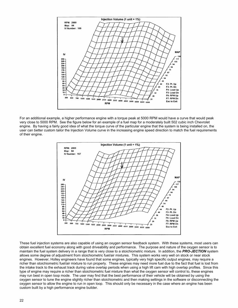
There are several different system configurations which can be run with a Holley PRO-JECTION system. The goal of the tuning procedure is the same for each system. However, the actual procedure for tuning the system will vary according to the actual system purchased, the way the user configures the system, and to some extent, the type of engine that the system is installed on. The tuning procedures will be broken down into four different possible PRO-JECTION system configurations. These are the PRO-JECTION D system with either closed (oxygen sensor feedback mode) or open loop operation and the PRO-JECTION Di system with either closed or open loop operation. In general, the goal of the tuning process should be to develop a fuel map that corresponds to a slightly richer than stoichiometric (or chemically perfect) fuel mixture. It is preferable to run the engine slightly rich particularly at high throttle settings. Significant engine damage can occur quickly from overheating inside the cylinders if extended running is done at a high throttle position and with a lean fuel mixture. Many engines will make slightly more power running at a slightly lean condition but the user should be discouraged from running at this condition. Holley engineers have found that the best engine performance can be felt in a “band” around the optimum fuel mixture. A minimum amount of performance difference can be found within the extremes of this band and Holley recommends that the user tune to the rich side of this band. This will generally result in a slightly rich map (around 10-20%) that will give very good performance without sacrificing performance, economy, driveability, or engine durability. 11.2 Oxygen Sensor Effect on Performance For some users, it may seem like a waste of fuel to map the system richer than stoichiometric. For those users who may be running a fairly stock engine and are interested in fuel economy, they should keep in mind that running a PRO-JECTION D or Di system in closed loop (relying primarily on oxygen sensor-fuel mixture feedback) will safely adjust all part throttle operation back to stoichiometric. Therefore, the PRO-JECTION systems will give optimum fuel economy during normal engine operation. However, any of the PRO-JECTION systems will revert to open loop operation at wide open throttle settings which rely on the users fuel tuning process. With this in mind, at high throttle settings, the system needs to be tuned richer than stoichiometric. 11.3 Engine Configuration Related Concerns The Holley PRO-JECTION systems have been designed to provide the versatility needed to be custom tailored to most any applications and will provide very good performance for a variety of engine sizes and engine types. In addition, the user can make the tuning process much easier and understandable by knowing a little about their engine and understanding how the fuel system delivery interacts with their engine requirements. Both the D and the Di systems allow the user to custom tune the engine fuel curve to match the engine requirements. In addition, the Di system allows the user to visually see the Injection Volume fuel map using Holley software and a PC connected to the PRO-JECTION ECU. The D system user can purchase this software as Holley part number 534-44. The D system user can use this software to monitor the system operation but not make changes with the software. An example of this Injection Volume fuel map is shown below. This particular fuel map was made for a marine Ford 460 cubic inch engine with a relatively mild cam. The user should notice that the fuel delivery will generally increase steadily as the map pressure reading (or engine load) increases or vacuum decreases. This can be seen by looking at a particular engine speed on the graph and following that same engine speed line in the direction of increasing map pressure. The increase in this direction at a given speed will be fairly linear or be a fairly smooth straight line that is always increasing. However, the fuel map curve looks very different when looking at constant map pressure values and looking across increasing speed values. The fuel curve in this direction will generally steadily increase to a peak and start to drop off above some speed. In the example figure, this speed of peak fuel injection amount is approximately 3500 RPM. The peak Injection Volume amount will correspond to the engine speed where maximum torque is developed or in more technical terms, the peak engine volumetric efficiency.
22
For an additional example, a higher performance engine with a torque peak at 5000 RPM would have a curve that would peak very close to 5000 RPM. See the figure below for an example of a fuel map for a moderately built 502 cubic inch Chevrolet engine. By having a fairly good idea of what the torque curve of the particular engine that the system is being installed on, the user can better custom tailor the Injection Volume curve in the increasing engine speed direction to match the fuel requirements of their engine.
These fuel injection systems are also capable of using an oxygen sensor feedback system. With these systems, most users can obtain excellent fuel economy along with good driveability and performance. The purpose and nature of the oxygen sensor is to maintain the fuel system delivery in a range that is very close to a stoichiometric mixture. In addition, the PRO-JECTION system allows some degree of adjustment from stoichiometric fuel/air mixtures. This system works very well on stock or near stock engines. However, Holley engineers have found that some engines, typically very high specific output engines, may require a richer than stoichiometric fuel/air mixture to run properly. These engines may need more fuel due to the fact that fuel is lost from the intake track to the exhaust track during valve overlap periods when using a high lift cam with high overlap profiles. Since this type of engine may require a richer than stoichiometric fuel mixture than what the oxygen sensor will control to, these engines may run best in open loop mode. The user may find that the best performance of their vehicle will be obtained by using the oxygen sensor to tune the engine slightly richer than stoichiometric and then making settings in the software or disconnecting the oxygen sensor to allow the engine to run in open loop. This should only be necessary in the case where an engine has been custom built by a high performance engine builder.

23
12.0 GETTING STARTED TUNING AND PROGRAMMING (D SYSTEM) 12.1 Tuning Tips (Skip to section 13.0 if you are tuning a Di system.) This system allows the user to performance tune the system based on his or her best judgment for how the engine feels. A calibration module allows the user to tune the system while the vehicle is in motion giving instantaneous system operation feedback. The D system uses the same fuel map as the Di system but each knob on the calibration module controls large portions of the map rather than individual points as is done with the Di system. This makes it very easy for the user to turn a knob while feeling the engine response. The user should find a band of adjustment with the knob where engine performance will be best. Holley recommends that the knob be turned towards clockwise side, or rich side, of the band of best performance to ensure that the engine fuel map is slightly rich. The same tuning procedure should be used whether the PRO-JECTION system is going to be used in either open or closed loop mode. The only difference is the closed loop PRO-JECTION system will adjust the part throttle fuel delivery to a stoichiometric fuel/air mixture. 12.2 Calibration Module Controls The PRO-JECTION D system is calibrated using a plug in control unit called a calibration module. The calibration module is used to change 6 different fuel mixture features in the fuel data. The SAVE button on the calibration module is used to save the fuel map modifications to the ECU. The calibration module must be connected to the wiring harness of the ECU. The red indicator light will illuminate when connected properly and with the ignition power turned on. Initially, all the adjustment knobs should be set to the detent position which can be found by rotating each adjustment knob to its midpoint position. A slight resistance can be felt at the detent. NOTE: Whenever the calibration module is connected to the wiring harness, the ECU will not allow the engine to enter closed loop, or feedback mode. The module must be unplugged after the tuning of the engine to return to closed loop operation. WARNING! THE ADJUSTMENT KNOB FULL TRAVEL IS ¾ OF A REVOLUTION. DO NOT FORCE THE ADJUSTMENT KNOB PAST ITS STOPS OR DAMAGE TO THE CALIBRATION MODULE WILL RESULT. The calibration module contains 6 adjustment knobs. Four of the knobs have a specific functions and modify one of four regions of the fuel map. The Choke and Accel knobs adjust other data than what is contained in the fuel map. Each knob adjustment is detailed below: 1 - Low Jet - This knob adjusts the light throttle cruise segment of the fuel map. Turn the knob clockwise to richen the fuel mixture, and counterclockwise to lean the fuel mixture. 2 - Idle Trim - Fine adjustment of idle fuel, specifically below 1000 RPM. Turn the knob clockwise to richen the fuel mixture, and counterclockwise to lean the fuel mixture. 3 - Main Jet - This knob allows adjustment of the entire fuel map, either richer or leaner, just as changing main jets in a carburetor would do. Turn the adjustment knob clockwise to add fuel, or turn the knob counterclockwise to remove fuel. 4 - Hi-RPM Jet - This knob allows adjustment of the fuel delivery above 3000 RPM. Turn knob clockwise for additional fuel above 3000 RPM, or counterclockwise to remove fuel above 3000 RPM. 5 - Accel Pump - Allows fine tuning of the accelerator pump shot for different engine requirements. Turn knob clockwise to increase pump shot, turn counterclockwise to decrease. 6 - Choke - Adjusts warm up compensation for different engine requirements during cold start and engine warm up. 12.3 Tuning And Adjustment Procedures for a D System 1 - Turn the ignition key to the run position. Leave the ignition key in the run position until the electric fuel pump can be heard running. The pump will run about 10 seconds before shutting off. Start the vehicle. Immediately upon starting the vehicle, adjust the idle trim adjustment knob until the engine idles smoothly. If this cannot be achieved with the adjustment range of the idle trim knob, adjust the low jet knob until the engine idles smoothly. If the adjustment is inadequate, adjust the main jet knob (slightly) until the engine idles smoothly. Allow the engine to reach operating temperature. If the warm idle speed is too fast, go immediately to Step Number 6. After completing Step Number 6, return to Step
24
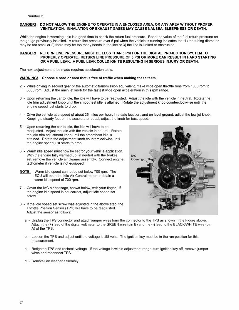
Number 2. DANGER! DO NOT ALLOW THE ENGINE TO OPERATE IN A ENCLOSED AREA, OR ANY AREA WITHOUT PROPER VENTILATION. INHALATION OF EXHAUST GASES MAY CAUSE NAUSEA, SLEEPINESS OR DEATH. While the engine is warming, this is a good time to check the return fuel pressure. Read the value of the fuel return pressure on the gauge previously installed. A return line pressure over 5 psi when the vehicle is running indicates that 1) the tubing diameter may be too small or 2) there may be too many bends in the line or 3) the line is kinked or obstructed. DANGER! RETURN LINE PRESSURE MUST BE LESS THAN 5 PSI FOR THE DIGITAL PROJECTION SYSTEM TO PROPERLY OPERATE. RETURN LINE PRESSURE OF 5 PSI OR MORE CAN RESULT IN HARD STARTING OR A FUEL LEAK. A FUEL LEAK COULD IGNITE RESULTING IN SERIOUS INJURY OR DEATH. The next adjustment to be made requires acceleration tests. WARNING! Choose a road or area that is free of traffic when making these tests. 2 - While driving in second gear or the automatic transmission equivalent, make wide open throttle runs from 1000 rpm to 3000 rpm. Adjust the main jet knob for the fastest wide open acceleration in this rpm range. 3 - Upon returning the car to idle, the idle will have to be readjusted. Adjust the idle with the vehicle in neutral. Rotate the idle trim adjustment knob until the smoothest idle is attained. Rotate the adjustment knob counterclockwise until the engine speed just starts to drop. 4 - Drive the vehicle at a speed of about 25 miles per hour, in a safe location, and on level ground, adjust the low jet knob. Keeping a steady foot on the accelerator pedal, adjust the knob for best speed. 5 - Upon returning the car to idle, the idle will have to be readjusted. Adjust the idle with the vehicle in neutral. Rotate the idle trim adjustment knob until the smoothest idle is attained. Rotate the adjustment knob counterclockwise until the engine speed just starts to drop. 6 - Warm idle speed must now be set for your vehicle application. With the engine fully warmed up, in neutral with the brakes set, remove the vehicle air cleaner assembly. Connect engine tachometer if vehicle is not equipped. NOTE: Warm idle speed cannot be set below 700 rpm. The ECU will open the Idle Air Control motor to obtain a warm idle speed of 700 rpm. 7 - Cover the IAC air passage, shown below, with your finger. If the engine idle speed is not correct, adjust idle speed set screw. 8 - If the idle speed set screw was adjusted in the above step, the Throttle Position Sensor (TPS) will have to be readjusted. Adjust the sensor as follows: a - Unplug the TPS connector and attach jumper wires form the connector to the TPS as shown in the Figure above. Attach the (+) lead of the digital voltmeter to the GREEN wire (pin B) and the (-) lead to the BLACK/WHITE wire (pin A) of the TPS. b - Loosen the TPS and adjust until the voltage is .58 volts. The ignition key must be in the run position for this measurement. c - Retighten TPS and recheck voltage. If the voltage is within adjustment range, turn ignition key off, remove jumper wires and reconnect TPS. d - Reinstall air cleaner assembly.

25
7 - Repeat steps 2, 3, 4, and 5. 8 - Adjust the accel pump adjustment knob by having an assistant follow the vehicle and watch the tailpipe. If the engine bogs (sluggish) and a puff of black smoke comes from the tailpipe, indicating too much fuel, adjust the accel pump counterclockwise. If the engine hesitates or backfires and no smoke exits the tailpipe, indicating too little fuel, adjust the accel pump clockwise. 9 - The Hi-rpm jet adjustment is adjusted by driving the vehicle in second gear, or the automatic transmission equivalent. WARNING! Choose a road or area that is free of traffic when making these tests. Make full throttle passes from 3000 rpm up. Adjust the Hi-rpm knob for the quickest results. NOTE: The DIGITAL PROJECTION rev limiter is preset at 5000 rpm. Fuel is shut off intermittently at this rpm to prevent engine over-revving. 10 - The Choke knob adds or subtracts fuel during engine warm up. If your engine requires more fuel during warm up, i.e. backfires through intake, stumbles, add more warm up fuel by adjusting the Choke knob clockwise. If your engine requires less fuel during warm up, i.e. black smoke, missing, remove fuel by adjusting the Choke knob counterclockwise. 11 - After the above tuning process has been completed, the values must be saved to the ECU. During the save process, the Rev-Limit will also be set into memory. To save the calibration module values and set the rev-limiter, hold the engine speed at ½ the desired rev-limit RPM. Example: To obtain a rev-limit value of 6000 RPM, hold the engine speed at 3000 RPM during the save process. Press the “HOLD” button on the calibration module momentarily to save the calibration and rev-limit values. The engine will miss briefly (less than 1 second). This tells the operator that these values have been stored in the ECU. The calibration module can now be disconnected from the ECU. WARNING! Pull off the road before saving the calibration module settings and rev-limit value. Failure to do so could cause a loss of power or brakes, which could cause personal injury or property damage in the event of an accident. NOTE: The ECU will not enter feedback, or closed loop, mode until the calibration module is disconnected. Upon disconnecting the calibration module, the oxygen sensor will further trim the fuel for maximum performance and fuel economy. WARNING! Tuning must be done before disconnecting the calibration module. The oxygen sensor can only adjust the fuel by a small amount. If tuning is not completed and stored, engine damage could result. NOTE: If the engine speed is not above 1750 RPM during the save process, the rev limiter will automatically default to 3500 RPM. 13.0 GETTING STARTED TUNING AND PROGRAMMING (Di SYSTEM)
26
13.1 Software Installation and Software Operational Description An IBM compatible personal computer (preferably a laptop for portability) with EGA (or better) monitor is required for adjustment with the Di system. The PC must have DOS level 6.0 or Windows 3.1 or Windows 95 to run the Holley software package. The software is not designed to use a mouse with the DOS and Windows 3.1 Versions, but will run with Windows 95. The Holley software package allows modification of the Spark Advance, Oxygen Trigger Voltage, Idle RPM Parameters, Temperature Compensation tables, and the complete fuel map. NOTE: Read through the entire tuning and adjustment portion of the manual before attempting to modify any maps. DANGER! HAVE AN ASSISTANT TO MONITOR THE SOFTWARE PACKAGE OR TO OPERATE THE VEHICLE DURING TUNING AND ADJUSTMENT. FAILURE TO KEEP A SAFE DISTANCE FROM OTHER VEHICLES AND FOLLOW ALL SAFETY PRECAUTIONS. LAWS, RULES AND REGULATIONS CAN LEAD TO PROPERTY DAMAGE, SERIOUS INJURY AND/OR DEATH! 13.1.1 Windows 95 1 - Insert disk 1 of 4 labeled for Windows 95. 2 - Select the START menu at the bottom left hand area of the computer screen. 3 - On the pop up menu select RUN. 4 - Type A:\SETUP.EXE in the command line box and click OK. This will begin the installation of the software. Follow the on-screen information. 13.1.2 Windows 3.1 1 - Insert Disk labeled for Windows 3.1 and DOS into the floppy drive. Type SETUP A: or(B:) C: EEV30 and press Enter. You may substitute another drive for "C:" which is the destination drive. You may substitute another directory name for EEV30. When the DOS portion of the installation is completed, exit the DOS session. 2 - From the Window Program Manager menu: Select File. Select New. On the New Program Object dialog box Select the Program Group Radio Button. Click the OK button. 3 - On the Program Group Properties dialog box: For Description type Holley EEV 3.0. For the Group File type EEV. Click the OK button. 4 - From the Windows Program Manger menu: Select File. Select New. Click the OK button. On the New Program Object dialog box select the Program Item Radio Button. Click the OK button. 5 - On the Program Item Properties dialog box: For Description type EEV 3.0. For Command Line type the Drive, Directory and EEV30WIN.EXE. If you installed the software on the C: drive in the EEV30 directory then you would type C:\EEV30\EEV30WIN.EXE. For Working Directory type the Drive and Directory where the software was installed. For Shortcut Key leave None. 6 - Click the Change Icon button. Click Ok button on the message box that comes up. On the Change Icon dialog box, click the Browse button. On the Browse dialog box: For Drives select the Drive onto which you installed the software. For Directories select the Directory into which you installed the software. For File Name click on the HOLLEY.ICO file. Click the OK button. 7 - On the Change Icon dialog box: Click the OK button. 8 - On the Program Item Properties dialog box: Click the OK button. 13.1.3 DOS Installation Insert disk labeled for Windows 3.1 and DOS into the floppy drive. Type Install A:(or B:) C: EEV30 and press Enter. You may substitute another drive for "C:", which is the destination drive. You may substitute another directory name for EEV30. When

27
the DOS portion of the installation is completed, you can start the program by typing EEV and pressing the Enter key This software is comprised of three development tools: Mapview, Data Monitor, and EEprom Programming. Mapview displays the main Injection Volume map and is used while the engine is running. Data Monitor provides system information while the engine is running. EEprom Programming allows modification of the fuel and spark values used by the ECU. The first screen you will enter will look like the following:
13.2 Mapview Once the ECU is connected and the engine is running, Mapview can be selected from the main menu. If the PC is connected correctly and the ECU is active, the Injection Volume map will be displayed in graphical form. The displayed graph shows the Injection Volume curve. The X (horizontal) axis of the graph is engine RPM. The Y (vertical) axis is manifold pressure in kPa. A moving pointer indicates the current operating point of the running engine. As RPM increases, the pointer will move to the right. As the load increases, the pointer will move towards the top of the graph. When changes are made to the Injection Volume map, either with the calibration module or EEprom programmer, they are displayed in Mapview. Press the “Esc” key to exit from Mapview. 13.3 Data Monitor The Data Monitor program requires that the ECU be active and connected to the PC. This program displays the sensor values and operating parameters in text form. NOTE: If your screen displays the following message: “Data Transmission Error!! Trying to fix Error!!” Make sure that the key has been turned on, the ECU is getting power, and check to make that there is not a loose connection between the ECU and the PC. This message may display occasionally due to the communication speed difference between the laptop and the ECU. This information can be used to troubleshoot the system installation. In the event that the engine temperature, air charge temperature, manifold pressure, or throttle sensors are faulty or disconnected, the Data Monitor software will display “BAD” next to the sensor name. If the sensor is operational, the value received by the ECU will be displayed. The Injection Volume, after Oxy Comp, will be displayed. This is in conjunction with the injector opening duration. Also displayed is the amount of compensation due to the oxygen sensor feedback signal. When the Ignition control function is utilized, the Ignition Type and Spark Advance will be displayed. Calibration module values, if saved, will be displayed across the bottom of the monitor. Press the “Esc” key to exit Data Monitor.
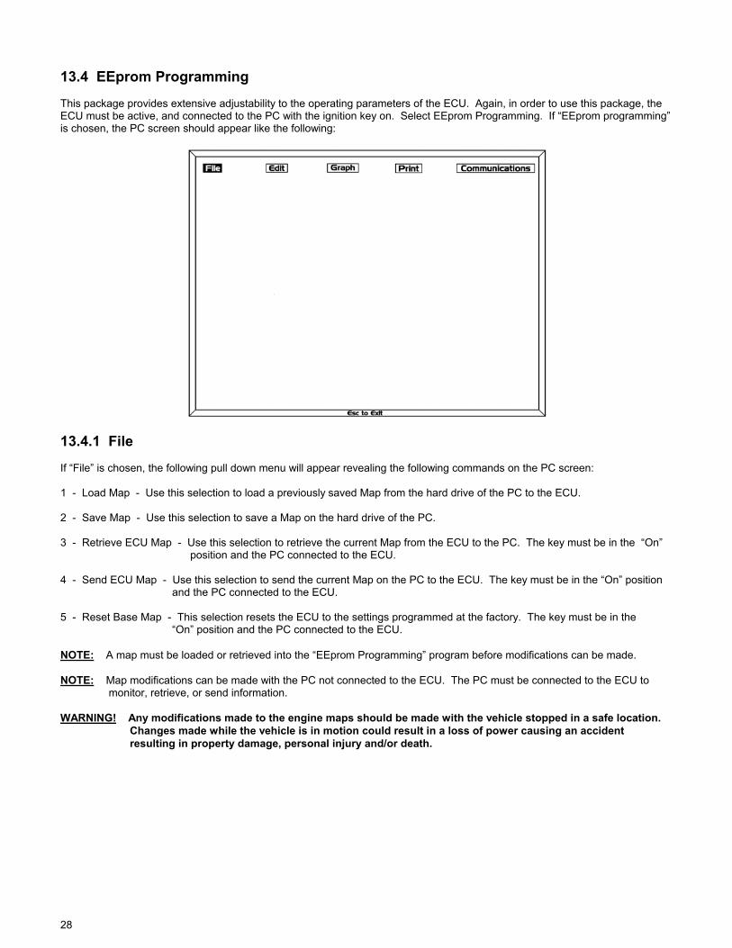
28
13.4 EEprom Programming This package provides extensive adjustability to the operating parameters of the ECU. Again, in order to use this package, the ECU must be active, and connected to the PC with the ignition key on. Select EEprom Programming. If “EEprom programming” is chosen, the PC screen should appear like the following:
13.4.1 File If “File” is chosen, the following pull down menu will appear revealing the following commands on the PC screen: 1 - Load Map - Use this selection to load a previously saved Map from the hard drive of the PC to the ECU. 2 - Save Map - Use this selection to save a Map on the hard drive of the PC. 3 - Retrieve ECU Map - Use this selection to retrieve the current Map from the ECU to the PC. The key must be in the “On” position and the PC connected to the ECU. 4 - Send ECU Map - Use this selection to send the current Map on the PC to the ECU. The key must be in the “On” position and the PC connected to the ECU. 5 - Reset Base Map - This selection resets the ECU to the settings programmed at the factory. The key must be in the “On” position and the PC connected to the ECU. NOTE: A map must be loaded or retrieved into the “EEprom Programming” program before modifications can be made. NOTE: Map modifications can be made with the PC not connected to the ECU. The PC must be connected to the ECU to monitor, retrieve, or send information. WARNING! Any modifications made to the engine maps should be made with the vehicle stopped in a safe location. Changes made while the vehicle is in motion could result in a loss of power causing an accident resulting in property damage, personal injury and/or death.
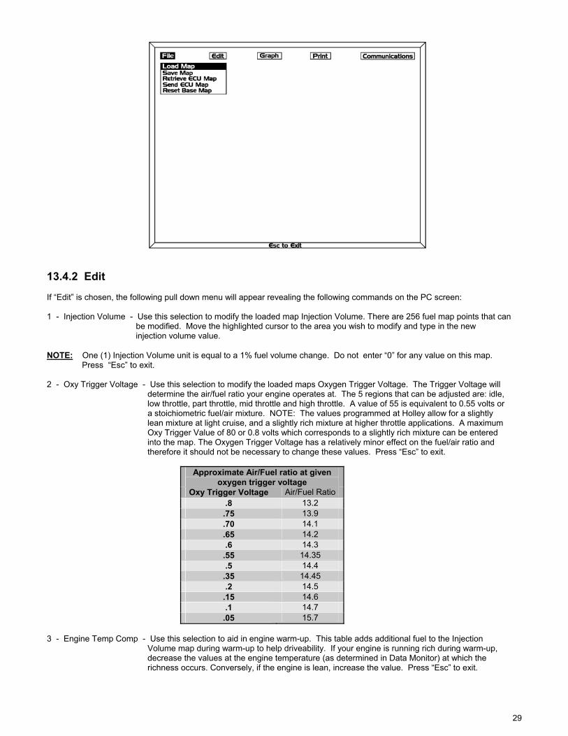
29
13.4.2 Edit If “Edit” is chosen, the following pull down menu will appear revealing the following commands on the PC screen: 1 - Injection Volume - Use this selection to modify the loaded map Injection Volume. There are 256 fuel map points that can be modified. Move the highlighted cursor to the area you wish to modify and type in the new injection volume value. NOTE: One (1) Injection Volume unit is equal to a 1% fuel volume change. Do not enter “0” for any value on this map. Press “Esc” to exit. 2 - Oxy Trigger Voltage - Use this selection to modify the loaded maps Oxygen Trigger Voltage. The Trigger Voltage will determine the air/fuel ratio your engine operates at. The 5 regions that can be adjusted are: idle, low throttle, part throttle, mid throttle and high throttle. A value of 55 is equivalent to 0.55 volts or a stoichiometric fuel/air mixture. NOTE: The values programmed at Holley allow for a slightly lean mixture at light cruise, and a slightly rich mixture at higher throttle applications. A maximum Oxy Trigger Value of 80 or 0.8 volts which corresponds to a slightly rich mixture can be entered into the map. The Oxygen Trigger Voltage has a relatively minor effect on the fuel/air ratio and therefore it should not be necessary to change these values. Press “Esc” to exit.
Approximate Air/Fuel ratio at given oxygen trigger voltage
Oxy Trigger Voltage Air/Fuel Ratio .8 13.2
.75 13.9
.70 14.1
.65 14.2 .6 14.3
.55 14.35 .5 14.4
.35 14.45 .2 14.5
.15 14.6 .1 14.7
.05 15.7 3 - Engine Temp Comp - Use this selection to aid in engine warm-up. This table adds additional fuel to the Injection Volume map during warm-up to help driveability. If your engine is running rich during warm-up, decrease the values at the engine temperature (as determined in Data Monitor) at which the richness occurs. Conversely, if the engine is lean, increase the value. Press “Esc” to exit.
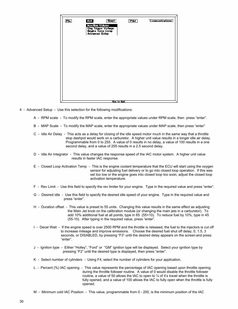
30
4 - Advanced Setup - Use this selection for the following modifications: A - RPM scale - To modify the RPM scale, enter the appropriate values under RPM scale, then press “enter”. B - MAP Scale - To modify the MAP scale, enter the appropriate values under MAP scale, then press “enter” C - Idle Air Delay - This acts as a delay for closing of the idle speed motor much in the same way that a throttle stop dashpot would work on a carburetor. A higher unit value results in a longer idle air delay. Programmable from 0 to 255. A value of 0 results in no delay, a value of 100 results in a one second delay, and a value of 255 results in a 2.5 second delay. D - Idle Air Integrator - This value changes the response speed of the IAC motor system. A higher unit value results in faster IAC response. E - Closed Loop Activation Temp - This is the engine coolant temperature that the ECU will start using the oxygen sensor for adjusting fuel delivery or to go into closed loop operation. If this was set too low or the engine goes into closed loop too soon, adjust the closed loop activation temperature. F - Rev Limit - Use this field to specify the rev limiter for your engine. Type in the required value and press “enter”. G - Desired idle - Use this field to specify the desired idle speed of your engine. Type in the required value and press “enter”. H - Duration offset - This value is preset to 55 units. Changing this value results in the same effect as adjusting the Main Jet knob on the calibration module (or changing the main jets in a carburetor). To add 10% additional fuel at all points, type in 65 (55+10). To reduce fuel by 10%, type in 45 (55-10). After typing in the required value, press “enter”. I - Decel Wait - If the engine speed is over 2500 RPM and the throttle is released, the fuel to the injectors is cut off to increase mileage and improve emissions. Choose the desired fuel shut off delay, 0, 1.5, 3 seconds, or DISABLED, by pressing “F3” until the desired delay appears on the screen and press “enter”. J - Ignition type - Either “Holley”, “Ford” or “GM” ignition type will be displayed. Select your ignition type by pressing “F2” until the desired type is displayed, then press “enter”. K - Select number of cylinders - Using F4, select the number of cylinders for your application. L - Percent (%) IAC opening - This value represents the percentage of IAC opening based upon throttle opening during the throttle follower routine. A value of 0 would disable the throttle follower routine, a value of 50 allows the IAC to open to ½ of it’s travel when the throttle is fully opened, and a value of 100 allows the IAC to fully open when the throttle is fully opened. M - Minimum cold IAC Position - This value, programmable from 0 - 200, is the minimum position of the IAC
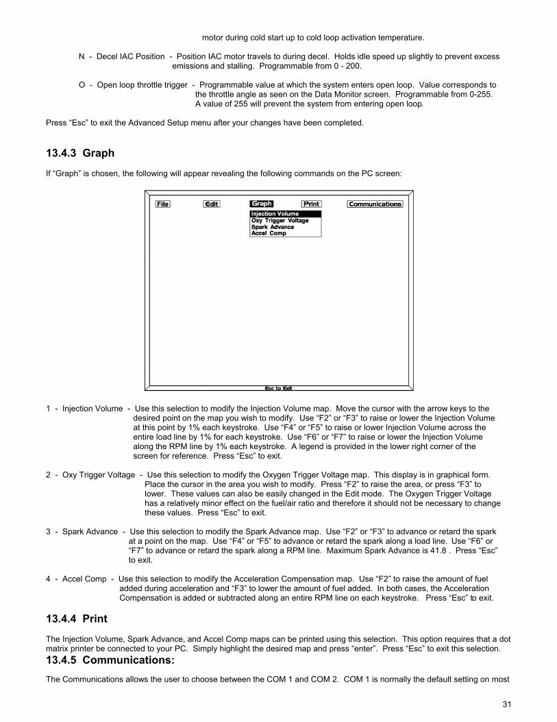
31
motor during cold start up to cold loop activation temperature. N - Decel IAC Position - Position IAC motor travels to during decel. Holds idle speed up slightly to prevent excess emissions and stalling. Programmable from 0 - 200. O - Open loop throttle trigger - Programmable value at which the system enters open loop. Value corresponds to the throttle angle as seen on the Data Monitor screen. Programmable from 0-255. A value of 255 will prevent the system from entering open loop. Press “Esc” to exit the Advanced Setup menu after your changes have been completed. 13.4.3 Graph If “Graph” is chosen, the following will appear revealing the following commands on the PC screen:
1 - Injection Volume - Use this selection to modify the Injection Volume map. Move the cursor with the arrow keys to the desired point on the map you wish to modify. Use “F2” or “F3” to raise or lower the Injection Volume at this point by 1% each keystroke. Use “F4” or “F5” to raise or lower Injection Volume across the entire load line by 1% for each keystroke. Use “F6” or “F7” to raise or lower the Injection Volume along the RPM line by 1% each keystroke. A legend is provided in the lower right corner of the screen for reference. Press “Esc” to exit. 2 - Oxy Trigger Voltage - Use this selection to modify the Oxygen Trigger Voltage map. This display is in graphical form. Place the cursor in the area you wish to modify. Press “F2” to raise the area, or press “F3” to lower. These values can also be easily changed in the Edit mode. The Oxygen Trigger Voltage has a relatively minor effect on the fuel/air ratio and therefore it should not be necessary to change these values. Press “Esc” to exit. 3 - Spark Advance - Use this selection to modify the Spark Advance map. Use “F2” or “F3” to advance or retard the spark at a point on the map. Use “F4” or “F5” to advance or retard the spark along a load line. Use “F6” or “F7” to advance or retard the spark along a RPM line. Maximum Spark Advance is 41.8 . Press “Esc” to exit. 4 - Accel Comp - Use this selection to modify the Acceleration Compensation map. Use “F2” to raise the amount of fuel added during acceleration and “F3” to lower the amount of fuel added. In both cases, the Acceleration Compensation is added or subtracted along an entire RPM line on each keystroke. Press “Esc” to exit. 13.4.4 Print The Injection Volume, Spark Advance, and Accel Comp maps can be printed using this selection. This option requires that a dot matrix printer be connected to your PC. Simply highlight the desired map and press “enter”. Press “Esc” to exit this selection. 13.4.5 Communications: The Communications allows the user to choose between the COM 1 and COM 2. COM 1 is normally the default setting on most

32
PC’s.
13.5 Tuning Tips for a Di System Tuning with the PRO-JECTION Di System is much different than with a D System. An IBM compatible personal computer (preferably a laptop for portability) must be connected to the PRO-JECTION ECU. Like the D system, the goal of this tuning process is to obtain a fuel map that is slightly rich. The advantage with this system is the personal computer can be used to monitor and change various engine parameters during the tuning process. If one is operating the system with an oxygen sensor, it becomes very easy to make fuel map changes and monitor their affect with the oxygen sensor compensation value.
13.5.1 Tuning Tips for a Di System With an Oxygen Sensor (closed loop) The user can use the Data Monitor option in the personal computer software to determine the amount of fuel correction from the Oxy Comp value. The best performance results will be obtained if the engine is mapped slightly rich (10 - 20%). This value is determined in Data Monitor by observing the Oxy Comp value. The user should make small changes to the map during tuning and check for the desired results before continuing. Although this tuning procedure results in a slightly rich fuel map, using a Di System with an oxygen sensor will correct the actual fuel delivery back to a stoichiometric fuel/air mixture at part throttle settings to obtain optimum fuel economy. In addition, the Di System can be tuned using the procedure and calibration module exactly as explained in the calibration instructions for a D system in Section 12.0. The calibration module part number 534-41 is available for sale separately.
13.5.2 Other General Tuning Tips for a Di System (closed and open loop) 1 - Use Mapview to determine which area of the map your engine is operating in. 2 - Use Data Monitor to determine amount of fuel correction by value of Oxy Comp and RPM (closed loop systems only). 3 - Best results are obtained if the engine map is slightly rich (10 - 20%). This value is determined in Data Monitor by observing the Oxy Comp value (closed loop systems only). To read 20% on the rich side, the Oxy Comp value would read “-20%” (meaning the map has 20% more fuel than stoichiometric and the ECU is taking out 20% of the fuel). Conversely, a positive Oxy Comp value (+20%) would indicate a lean point (meaning the map has 20% less fuel than stoichiometric and the ECU is adding 20% fuel). 4 - Make small changes to the map during tuning. Check desired results before continuing. 5 - Smooth fuel curves as much as possible. Sharp, or even slight transitions in the fuel map can be felt by some drivers. An example of a smooth fuel curve is shown below.
6 - If injection duration at idle is around 1700 µsec and the idle fuel delivery is too rich, reduce fuel pressure as outlined in the testing and adjusting fuel pressure section in the back of this manual. If this method does not increase the injector duration, then it may be necessary for you to purchase smaller injectors.

33
13.6 Tuning and Adjustment Procedures for a Di System Section 13.3 covers the tuning of both Di systems both with and without an oxygen sensor feedback signal. Because much of the tuning procedure is the same and most steps apply to all Di system users, only one section has been written. However, paragraphs 6, 11, 13 and 14 can only be used by systems using an oxygen sensor. These sections should be skipped by a user without an oxygen sensor. Paragraphs 7 and 15 are added to help the user that does not have an oxygen sensor. The beginning of each of these paragraphs will inform the user to skip that paragraph if necessary. Any paragraph that does not start by specifically stating it only applies to only one system is intended for both system configurations. 1 - Load the Holley software package into your laptop computer following the procedures outlined above. Connect PC to the ECU using DB-9 cable provided. 2 - Enter EEprom Programming. Go to the File menu and select Load. Several different fuel maps are provided in the “Load Map” selection. One of these maps is the base map which is an average of all of the maps and is called Base8.216 there are 4 maps, choose the one which most closely corresponds to your engine displacement and horsepower. The user can also choose to use the average map Base8.216 as long as he realizes the average map will be a compromise for his application and may require more tuning. Make the choice that is most similar to your engine size, highlight the choice and press “enter”. This map will be loaded into the PC. Turn your ignition key to the “on” position and select Send ECU Map to send the map to the ECU. This will take a few seconds and the screen will prompt you when the programming is done. 3 - The Advanced Setup parameters should be set at this time. If you plan on using Spark Control, the Spark Control must be set for the proper ignition type using the F2 key before the engine can be started. Enter into “Advanced Setup” under the Edit menu and select the proper ignition type. In addition, use the arrow keys to go to the Rev Limit section and the desired idle setting and enter your desired maximum engine and idle speed. In addition, select a temperature that you would like to have the engine enter closed loop control mode. Holley has used a value of 110° F in the base maps for marine use, and 75° F for automotive use. This value can be adjusted up or down depending on where the user wants the ECU to go into closed loop. If the coolant temp monitored in the Data Monitor screen goes below this value during operation, the closed loop activation temperature may need to be adjusted down. Use the F4 key to select the proper number of cylinders for your engine. The other parameters will not need to be set or adjusted at this time. After selecting the proper map and choosing the proper Advanced Setup parameters, save the PRO-JECTION system map to your computer using a personally selected file name of up to eight characters under the File menu and re-send the map to the ECU. 4 - Turn the ignition key to the run position. Leave the ignition key in the run position until the electric fuel pump can be heard running. The pump will run for about 2-3 seconds before shutting off. Start the engine and allow the engine to idle. 5 - Allow the engine to warm up before tuning the Injection Volume map. This is a good time to check the return fuel pressure. Read the value of the fuel return pressure on the gauge previously installed. A return line pressure over 5 psig when the engine is running indicates that 1) the tubing diameter may be too small or 2) there may be too many bends in the line or 3) the line is kinked or obstructed. Any high return line pressure condition should be corrected before any further fuel map tuning is done. DANGER! RETURN LINE PRESSURE MUST BE LESS THAN 5 PSIG FOR THE DIGITAL PRO-JECTION SYSTEM TO PROPERLY OPERATE. RETURN LINE PRESSURE OF 5 PSIG OR MORE CAN RESULT IN HARD STARTING OR A FUEL LEAK. A FUEL LEAK COULD IGNITE RESULTING IN PROPERTY DAMAGE, SERIOUS INJURY AND/OR DEATH. 6 - Skip this paragraph and go to paragraph 7 if tuning without an oxygen sensor. Enter “Data Monitor” in the program software. Watch the Oxygen Voltage value and the Oxy Comp value. If the engine is idling satisfactorily, allow the engine to reach operating temperature. Now is a good time to verify proper fuel map tuning. If the engine map is too rich at idle, the Oxy Comp will be displayed with a negative value. If the engine map is too lean at idle, the Oxy Comp will be displayed with a positive value. The Oxygen Voltage should be rapidly changing between values of 0.1-0.9 volts. This indicates normal ECU closed loop operation. If the Oxygen Voltage is 0.0, this indicates either an oxygen sensor problem, a lean condition, or a wiring problem with this circuit. A relatively constant (reading ± 0.2 volts) Oxygen Voltage and an Oxy Comp value of 0% indicates that the engine is operating in open loop mode. The engine will normally operate in open loop mode on any startup until the engine reaches the closed loop operating temperature entered in the advance setup mode. Enter “EEprom Programming” and make the “Graph”, ”Injection Volume” menu selections. Move the arrow around the map using the arrow keys until the map arrow is located on the line of current idle speed. Change the Injection Volume value by pressing F6 or F7 to move the entire Injection Volume line up or down to either give a richer or leaner fuel mixture at the current idle RPM. Save the map, and send the map to the ECU. Go to paragraph 8.
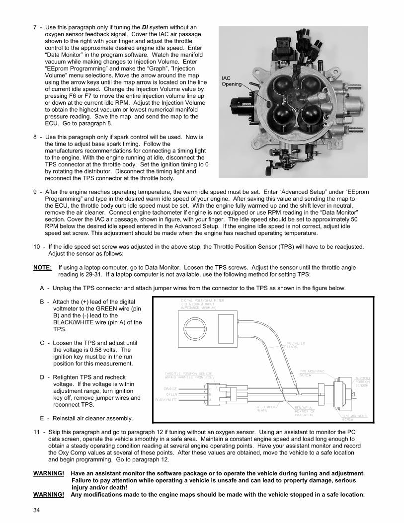
34
7 - Use this paragraph only if tuning the Di system without an oxygen sensor feedback signal. Cover the IAC air passage, shown to the right with your finger and adjust the throttle control to the approximate desired engine idle speed. Enter “Data Monitor” in the program software. Watch the manifold vacuum while making changes to Injection Volume. Enter “EEprom Programming” and make the “Graph”, ”Injection Volume” menu selections. Move the arrow around the map using the arrow keys until the map arrow is located on the line of current idle speed. Change the Injection Volume value by pressing F6 or F7 to move the entire injection volume line up or down at the current idle RPM. Adjust the Injection Volume to obtain the highest vacuum or lowest numerical manifold pressure reading. Save the map, and send the map to the ECU. Go to paragraph 8. 8 - Use this paragraph only if spark control will be used. Now is the time to adjust base spark timing. Follow the manufacturers recommendations for connecting a timing light to the engine. With the engine running at idle, disconnect the TPS connector at the throttle body. Set the ignition timing to 0 by rotating the distributor. Disconnect the timing light and reconnect the TPS connector at the throttle body. 9 - After the engine reaches operating temperature, the warm idle speed must be set. Enter “Advanced Setup” under “EEprom Programming” and type in the desired warm idle speed of your engine. After saving this value and sending the map to the ECU, the throttle body curb idle speed must be set. With the engine fully warmed up and the shift lever in neutral, remove the air cleaner. Connect engine tachometer if engine is not equipped or use RPM reading in the “Data Monitor” section. Cover the IAC air passage, shown in figure, with your finger. The idle speed should be set to approximately 50 RPM below the desired idle speed entered in the Advanced Setup. If the engine idle speed is not correct, adjust idle speed set screw. This adjustment should be made when the engine has reached operating temperature. 10 - If the idle speed set screw was adjusted in the above step, the Throttle Position Sensor (TPS) will have to be readjusted. Adjust the sensor as follows: NOTE: If using a laptop computer, go to Data Monitor. Loosen the TPS screws. Adjust the sensor until the throttle angle reading is 29-31. If a laptop computer is not available, use the following method for setting TPS: A - Unplug the TPS connector and attach jumper wires from the connector to the TPS as shown in the figure below. B - Attach the (+) lead of the digital voltmeter to the GREEN wire (pin B) and the (-) lead to the BLACK/WHITE wire (pin A) of the TPS. C - Loosen the TPS and adjust until the voltage is 0.58 volts. The ignition key must be in the run position for this measurement. D - Retighten TPS and recheck voltage. If the voltage is within adjustment range, turn ignition key off, remove jumper wires and reconnect TPS. E - Reinstall air cleaner assembly. 11 - Skip this paragraph and go to paragraph 12 if tuning without an oxygen sensor. Using an assistant to monitor the PC data screen, operate the vehicle smoothly in a safe area. Maintain a constant engine speed and load long enough to obtain a steady operating condition reading at several engine operating points. Have your assistant monitor and record the Oxy Comp values at several of these points. After these values are obtained, move the vehicle to a safe location and begin programming. Go to paragraph 12. WARNING! Have an assistant monitor the software package or to operate the vehicle during tuning and adjustment. Failure to pay attention while operating a vehicle is unsafe and can lead to property damage, serious injury and/or death! WARNING! Any modifications made to the engine maps should be made with the vehicle stopped in a safe location.
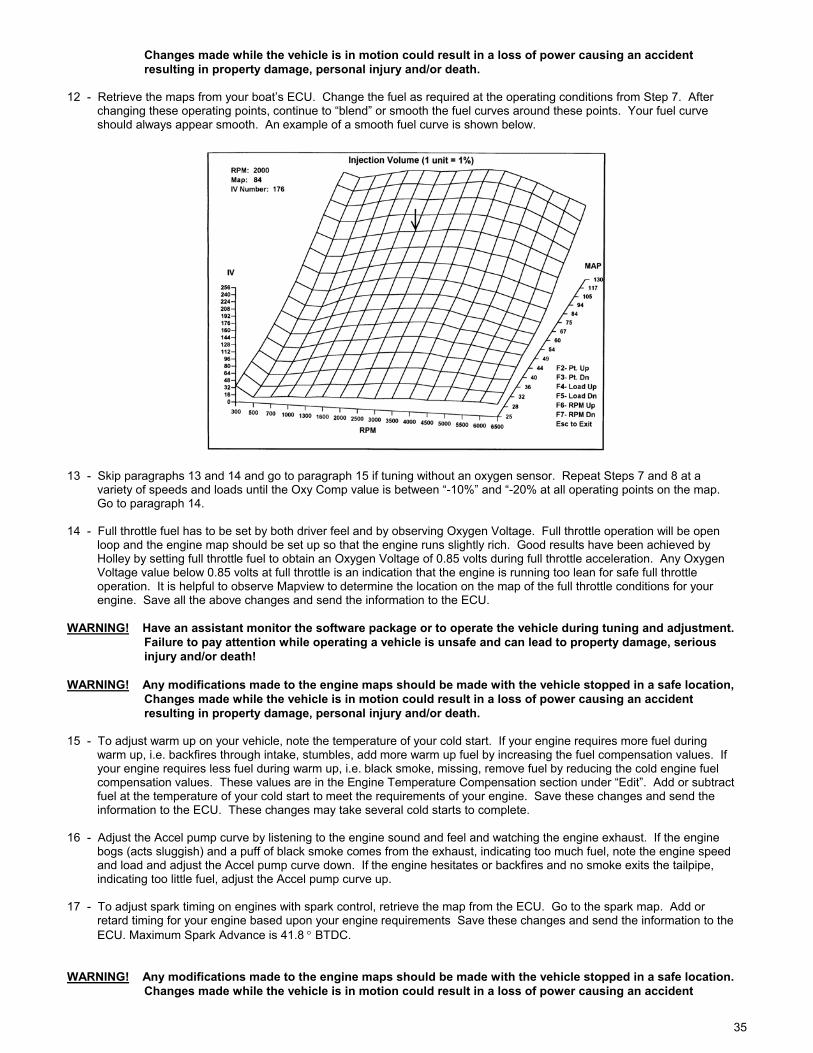
35
Changes made while the vehicle is in motion could result in a loss of power causing an accident resulting in property damage, personal injury and/or death. 12 - Retrieve the maps from your boat’s ECU. Change the fuel as required at the operating conditions from Step 7. After changing these operating points, continue to “blend” or smooth the fuel curves around these points. Your fuel curve should always appear smooth. An example of a smooth fuel curve is shown below.
13 - Skip paragraphs 13 and 14 and go to paragraph 15 if tuning without an oxygen sensor. Repeat Steps 7 and 8 at a variety of speeds and loads until the Oxy Comp value is between “-10%” and “-20% at all operating points on the map. Go to paragraph 14. 14 - Full throttle fuel has to be set by both driver feel and by observing Oxygen Voltage. Full throttle operation will be open loop and the engine map should be set up so that the engine runs slightly rich. Good results have been achieved by Holley by setting full throttle fuel to obtain an Oxygen Voltage of 0.85 volts during full throttle acceleration. Any Oxygen Voltage value below 0.85 volts at full throttle is an indication that the engine is running too lean for safe full throttle operation. It is helpful to observe Mapview to determine the location on the map of the full throttle conditions for your engine. Save all the above changes and send the information to the ECU. WARNING! Have an assistant monitor the software package or to operate the vehicle during tuning and adjustment. Failure to pay attention while operating a vehicle is unsafe and can lead to property damage, serious injury and/or death! WARNING! Any modifications made to the engine maps should be made with the vehicle stopped in a safe location, Changes made while the vehicle is in motion could result in a loss of power causing an accident resulting in property damage, personal injury and/or death. 15 - To adjust warm up on your vehicle, note the temperature of your cold start. If your engine requires more fuel during warm up, i.e. backfires through intake, stumbles, add more warm up fuel by increasing the fuel compensation values. If your engine requires less fuel during warm up, i.e. black smoke, missing, remove fuel by reducing the cold engine fuel compensation values. These values are in the Engine Temperature Compensation section under “Edit”. Add or subtract fuel at the temperature of your cold start to meet the requirements of your engine. Save these changes and send the information to the ECU. These changes may take several cold starts to complete. 16 - Adjust the Accel pump curve by listening to the engine sound and feel and watching the engine exhaust. If the engine bogs (acts sluggish) and a puff of black smoke comes from the exhaust, indicating too much fuel, note the engine speed and load and adjust the Accel pump curve down. If the engine hesitates or backfires and no smoke exits the tailpipe, indicating too little fuel, adjust the Accel pump curve up. 17 - To adjust spark timing on engines with spark control, retrieve the map from the ECU. Go to the spark map. Add or retard timing for your engine based upon your engine requirements Save these changes and send the information to the ECU. Maximum Spark Advance is 41.8 ° BTDC. WARNING! Any modifications made to the engine maps should be made with the vehicle stopped in a safe location. Changes made while the vehicle is in motion could result in a loss of power causing an accident
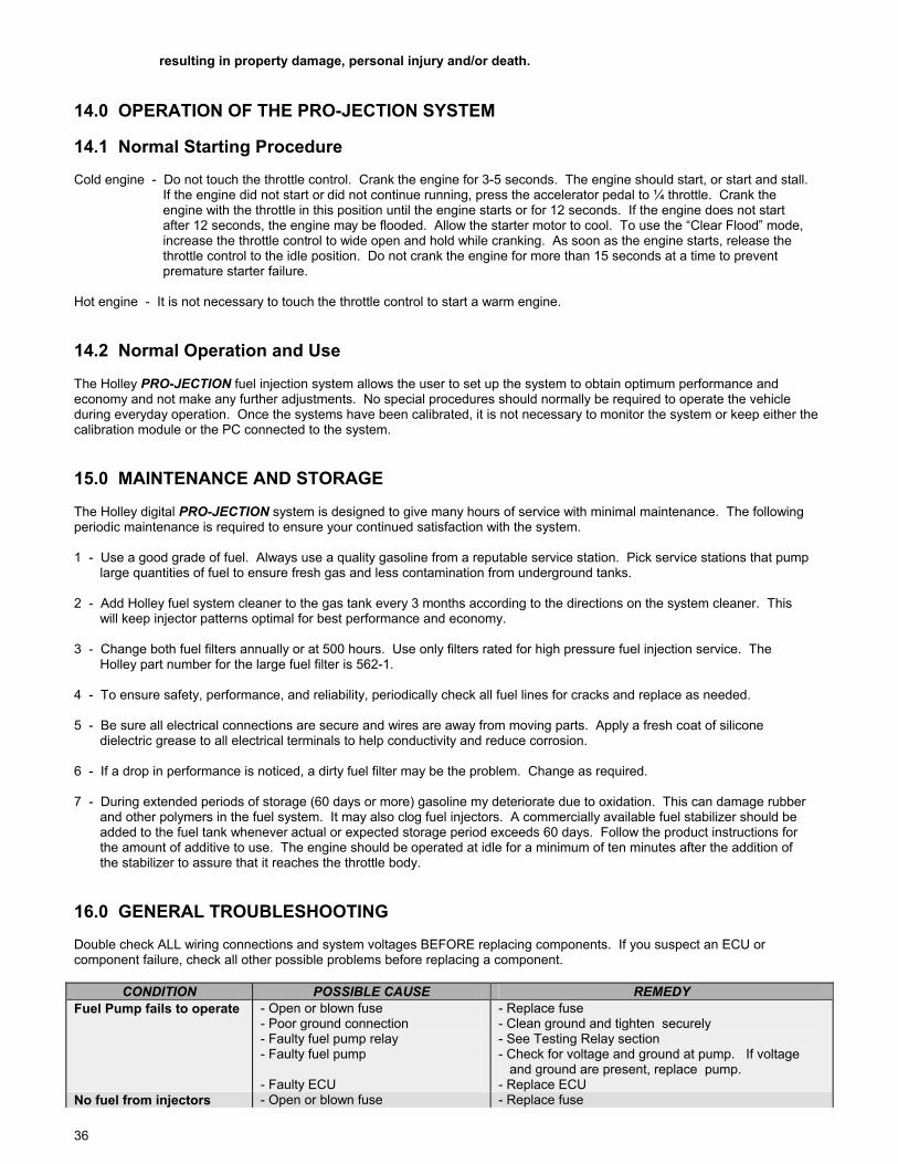
36
resulting in property damage, personal injury and/or death. 14.0 OPERATION OF THE PRO-JECTION SYSTEM 14.1 Normal Starting Procedure Cold engine - Do not touch the throttle control. Crank the engine for 3-5 seconds. The engine should start, or start and stall. If the engine did not start or did not continue running, press the accelerator pedal to ¼ throttle. Crank the engine with the throttle in this position until the engine starts or for 12 seconds. If the engine does not start after 12 seconds, the engine may be flooded. Allow the starter motor to cool. To use the “Clear Flood” mode, increase the throttle control to wide open and hold while cranking. As soon as the engine starts, release the throttle control to the idle position. Do not crank the engine for more than 15 seconds at a time to prevent premature starter failure. Hot engine - It is not necessary to touch the throttle control to start a warm engine. 14.2 Normal Operation and Use The Holley PRO-JECTION fuel injection system allows the user to set up the system to obtain optimum performance and economy and not make any further adjustments. No special procedures should normally be required to operate the vehicle during everyday operation. Once the systems have been calibrated, it is not necessary to monitor the system or keep either the calibration module or the PC connected to the system. 15.0 MAINTENANCE AND STORAGE The Holley digital PRO-JECTION system is designed to give many hours of service with minimal maintenance. The following periodic maintenance is required to ensure your continued satisfaction with the system. 1 - Use a good grade of fuel. Always use a quality gasoline from a reputable service station. Pick service stations that pump large quantities of fuel to ensure fresh gas and less contamination from underground tanks. 2 - Add Holley fuel system cleaner to the gas tank every 3 months according to the directions on the system cleaner. This will keep injector patterns optimal for best performance and economy. 3 - Change both fuel filters annually or at 500 hours. Use only filters rated for high pressure fuel injection service. The Holley part number for the large fuel filter is 562-1. 4 - To ensure safety, performance, and reliability, periodically check all fuel lines for cracks and replace as needed. 5 - Be sure all electrical connections are secure and wires are away from moving parts. Apply a fresh coat of silicone dielectric grease to all electrical terminals to help conductivity and reduce corrosion. 6 - If a drop in performance is noticed, a dirty fuel filter may be the problem. Change as required. 7 - During extended periods of storage (60 days or more) gasoline my deteriorate due to oxidation. This can damage rubber and other polymers in the fuel system. It may also clog fuel injectors. A commercially available fuel stabilizer should be added to the fuel tank whenever actual or expected storage period exceeds 60 days. Follow the product instructions for the amount of additive to use. The engine should be operated at idle for a minimum of ten minutes after the addition of the stabilizer to assure that it reaches the throttle body. 16.0 GENERAL TROUBLESHOOTING Double check ALL wiring connections and system voltages BEFORE replacing components. If you suspect an ECU or component failure, check all other possible problems before replacing a component.
CONDITION POSSIBLE CAUSE REMEDY Fuel Pump fails to operate - Open or blown fuse
- Poor ground connection - Faulty fuel pump relay - Faulty fuel pump - Faulty ECU
- Replace fuse - Clean ground and tighten securely - See Testing Relay section - Check for voltage and ground at pump. If voltage and ground are present, replace pump. - Replace ECU
No fuel from injectors - Open or blown fuse - Replace fuse
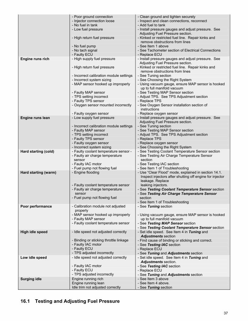
37
- Poor ground connection - Injector connection loose - No fuel in tank - Low fuel pressure - High return fuel pressure - No fuel pump - No tach signal - Faulty ECU
- Clean ground and tighten securely - Inspect and clean connections, reconnect - Add fuel to tank - Install pressure gauges and adjust pressure. See Adjusting Fuel Pressure section. - Kinked or restricted fuel line. Repair kinks and remove obstructions from lines - See Item 1 above - See Tachometer section of Electrical Connections - Replace ECU
Engine runs rich - High supply fuel pressure - High return fuel pressure - Incorrect calibration module settings - Incorrect system sizing - MAP sensor hooked up improperly - Faulty MAP sensor - TPS setting incorrect - Faulty TPS sensor - Oxygen sensor mounted incorrectly - Faulty oxygen sensor
- Install pressure gauges and adjust pressure. See Adjusting Fuel Pressure section. - Kinked or restricted fuel line. Repair kinks and remove obstructions from lines - See Tuning section - See Choosing the Right System - Using vacuum gauge, ensure MAP sensor is hooked up to full manifold vacuum - See Testing MAP Sensor section - Adjust TPS. See TPS Adjustment section - Replace TPS - See Oxygen Sensor installation section of instructions - Replace oxygen sensor
Engine runs lean - Low supply fuel pressure - Incorrect calibration module settings - Faulty MAP sensor - TPS setting incorrect - Faulty TPS sensor - Faulty oxygen sensor - Incorrect system sizing
- Install pressure gauges and adjust pressure. See Adjusting Fuel Pressure section. - See Tuning section - See Testing MAP Sensor section - Adjust TPS. See TPS Adjustment section - Replace TPS - Replace oxygen sensor - See Choosing the Right System
Hard starting (cold) - Faulty coolant temperature sensor - - Faulty air charge temperature sensor - Faulty IAC motor - Fuel pump not flowing fuel
- See Testing Coolant Temperature Sensor section - See Testing Air Charge Temperature Sensor section - See Testing IAC section - See Item 1 of Troubleshooting
Hard starting (warm) - Engine flooding - Faulty coolant temperature sensor - Faulty air charge temperature sensor - Fuel pump not flowing fuel
- Use “Clear Flood” mode, explained in section 14.1. Inspect injectors after shutting off engine for injector leakage. Replace leaking injectors. - See Testing Coolant Temperature Sensor section - See Testing Air Charge Temperature Sensor section - See Item 1 of Troubleshooting
Poor performance - Calibration module not adjusted properly - MAP sensor hooked up improperly - Faulty MAP sensor - Faulty coolant temperature sensor
- See Tuning section - Using vacuum gauge, ensure MAP sensor is hooked up to full manifold vacuum - See Testing MAP Sensor section - See Testing Coolant Temperature Sensor section
High idle speed - Idle speed not adjusted correctly - Binding or sticking throttle linkage - Faulty IAC motor - Faulty ECU - TPS adjusted incorrectly
- Set idle speed. See Item 4 in Tuning and Adjustments section - Find cause of binding or sticking and correct. - See Testing IAC section - Replace ECU - See Tuning and Adjustments section
Low idle speed - Idle speed not adjusted correctly - Faulty IAC motor - Faulty ECU - TPS adjusted incorrectly
- Set idle speed. See Item 4 in Tuning and Adjustments section. - See Testing IAC section - Replace ECU - See Tuning and Adjustments section
Surging idle Engine running rich Engine running lean Idle trim not adjusted correctly
- See Item 3 above - See Item 4 above. - See Tuning section
16.1 Testing and Adjusting Fuel Pressure
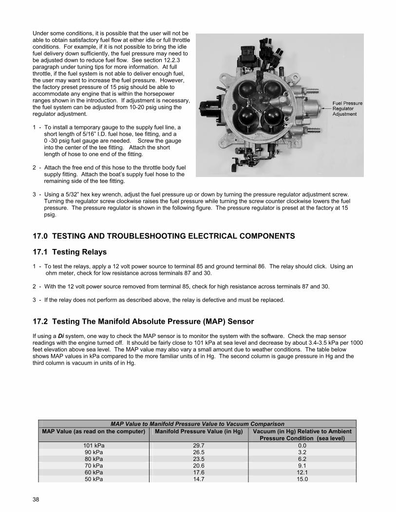
38
Under some conditions, it is possible that the user will not be able to obtain satisfactory fuel flow at either idle or full throttle conditions. For example, if it is not possible to bring the idle fuel delivery down sufficiently, the fuel pressure may need to be adjusted down to reduce fuel flow. See section 12.2.3 paragraph under tuning tips for more information. At full throttle, if the fuel system is not able to deliver enough fuel, the user may want to increase the fuel pressure. However, the factory preset pressure of 15 psig should be able to accommodate any engine that is within the horsepower ranges shown in the introduction. If adjustment is necessary, the fuel system can be adjusted from 10-20 psig using the regulator adjustment. 1 - To install a temporary gauge to the supply fuel line, a short length of 5/16” I.D. fuel hose, tee fitting, and a 0 -30 psig fuel gauge are needed. Screw the gauge into the center of the tee fitting. Attach the short length of hose to one end of the fitting. 2 - Attach the free end of this hose to the throttle body fuel supply fitting. Attach the boat’s supply fuel hose to the remaining side of the tee fitting. 3 - Using a 5/32” hex key wrench, adjust the fuel pressure up or down by turning the pressure regulator adjustment screw. Turning the regulator screw clockwise raises the fuel pressure while turning the screw counter clockwise lowers the fuel pressure. The pressure regulator is shown in the following figure. The pressure regulator is preset at the factory at 15 psig. 17.0 TESTING AND TROUBLESHOOTING ELECTRICAL COMPONENTS 17.1 Testing Relays 1 - To test the relays, apply a 12 volt power source to terminal 85 and ground terminal 86. The relay should click. Using an ohm meter, check for low resistance across terminals 87 and 30. 2 - With the 12 volt power source removed from terminal 85, check for high resistance across terminals 87 and 30. 3 - If the relay does not perform as described above, the relay is defective and must be replaced. 17.2 Testing The Manifold Absolute Pressure (MAP) Sensor If using a Di system, one way to check the MAP sensor is to monitor the system with the software. Check the map sensor readings with the engine turned off. It should be fairly close to 101 kPa at sea level and decrease by about 3.4-3.5 kPa per 1000 feet elevation above sea level. The MAP value may also vary a small amount due to weather conditions. The table below shows MAP values in kPa compared to the more familiar units of in Hg. The second column is gauge pressure in Hg and the third column is vacuum in units of in Hg.
MAP Value to Manifold Pressure Value to Vacuum Comparison MAP Value (as read on the computer) Manifold Pressure Value (in Hg) Vacuum (in Hg) Relative to Ambient
Pressure Condition (sea level) 101 kPa 29.7 0.0 90 kPa 26.5 3.2 80 kPa 23.5 6.2 70 kPa 20.6 9.1 60 kPa 17.6 12.1 50 kPa 14.7 15.0
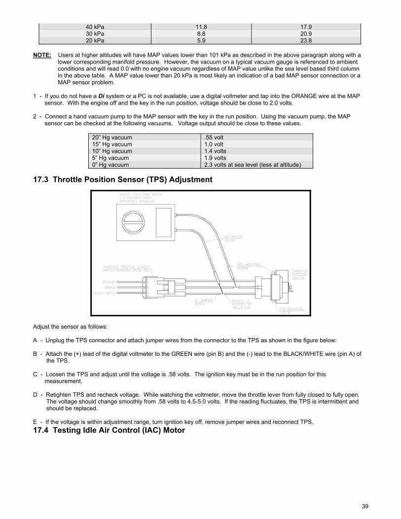
39
40 kPa 11.8 17.9 30 kPa 8.8 20.9 20 kPa 5.9 23.8
NOTE: Users at higher altitudes will have MAP values lower than 101 kPa as described in the above paragraph along with a lower corresponding manifold pressure. However, the vacuum on a typical vacuum gauge is referenced to ambient conditions and will read 0.0 with no engine vacuum regardless of MAP value unlike the sea level based third column in the above table. A MAP value lower than 20 kPa is most likely an indication of a bad MAP sensor connection or a MAP sensor problem. 1 - If you do not have a Di system or a PC is not available, use a digital voltmeter and tap into the ORANGE wire at the MAP sensor. With the engine off and the key in the run position, voltage should be close to 2.0 volts. 2 - Connect a hand vacuum pump to the MAP sensor with the key in the run position. Using the vacuum pump, the MAP sensor can be checked at the following vacuums. Voltage output should be close to these values.
20” Hg vacuum .55 volt 15” Hg vacuum 1.0 volt 10” Hg vacuum 1.4 volts 5” Hg vacuum 1.9 volts 0” Hg vacuum 2.3 volts at sea level (less at altitude)
17.3 Throttle Position Sensor (TPS) Adjustment
Adjust the sensor as follows: A - Unplug the TPS connector and attach jumper wires from the connector to the TPS as shown in the figure below: B - Attach the (+) lead of the digital voltmeter to the GREEN wire (pin B) and the (-) lead to the BLACK/WHITE wire (pin A) of the TPS. C - Loosen the TPS and adjust until the voltage is .58 volts. The ignition key must be in the run position for this measurement. D - Retighten TPS and recheck voltage. While watching the voltmeter, move the throttle lever from fully closed to fully open. The voltage should change smoothly from .58 volts to 4.5-5.0 volts. If the reading fluctuates, the TPS is intermittent and should be replaced. E - If the voltage is within adjustment range, turn ignition key off, remove jumper wires and reconnect TPS. 17.4 Testing Idle Air Control (IAC) Motor
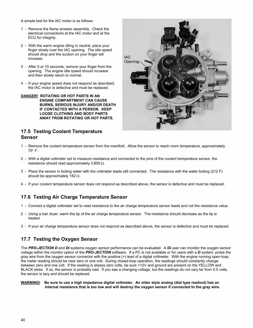
40
A simple test for the IAC motor is as follows: 1 - Remove the flame arrestor assembly. Check the electrical connections at the IAC motor and at the ECU for integrity. 2 - With the warm engine idling in neutral, place your finger slowly over the IAC opening. The idle speed should drop and the suction on your finger will increase. 3 - After 5 or 10 seconds, remove your finger from the opening. The engine idle speed should increase and then slowly return to normal. 4 - If your engine speed does not respond as described, the IAC motor is defective and must be replaced. DANGER! ROTATING OR HOT PARTS IN AN ENGINE COMPARTMENT CAN CAUSE BURNS, SERIOUS INJURY AND/OR DEATH IF CONTACTED WITH A PERSON. KEEP LOOSE CLOTHING AND BODY PARTS AWAY FROM ROTATING OR HOT PARTS.
17.5 Testing Coolant Temperature Sensor 1 - Remove the coolant temperature sensor from the manifold. Allow the sensor to reach room temperature, approximately 70° F. 2 - With a digital voltmeter set to measure resistance and connected to the pins of the coolant temperature sensor, the resistance should read approximately 3,800 Ω. 3 - Place the sensor in boiling water with the voltmeter leads still connected. The resistance with the water boiling (212 F) should be approximately 182 Ω. 4 - If your coolant temperature sensor does not respond as described above, the sensor is defective and must be replaced. 17.6 Testing Air Charge Temperature Sensor 1 - Connect a digital voltmeter set to read resistance to the air charge temperature sensor leads and not the resistance value. 2 - Using a hair dryer, warm the tip of the air charge temperature sensor. The resistance should decrease as the tip is heated. 3 - If your air charge temperature sensor does not respond as described above, the sensor is defective and must be replaced.
17.7 Testing the Oxygen Sensor The PRO-JECTION D and Di systems oxygen sensor performance can be evaluated. A Di user can monitor the oxygen sensor voltage within the monitor option of the PRO-JECTION software. If a PC is not available or for users with a D system, probe the gray wire from the oxygen sensor connector with the positive (+) lead of a digital voltmeter. With the engine running open-loop, the meter reading should be near zero or one volt. During closed-loop operation, the readings should constantly change between zero and one volt. If the reading is always zero volts, be sure +12V and ground are present on the YELLOW and BLACK wires. If so, the sensor is probably bad. If you see a changing voltage, but the readings do not vary far from 0.5 volts, the sensor is lazy and should be replaced. WARNING! Be sure to use a high impedance digital voltmeter. An older style analog (dial type readout) has an internal resistance that is too low and will destroy the oxygen sensor if connected to the gray wire.

41
NOTES: NOTES:

42
Copyright 2000 Holley Printed in U.S.A. Performance Products Inc 199R-10022-1 Date: 3-28-00