Embed Size (px)
Citation preview
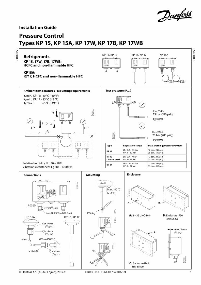
Installation Guide
Pressure Control Types KP 15, KP 15A, KP 17W, KP 17B, KP 17WB
© Danfoss A/S (AC-MCI / jmn), 2012-11 DKRCC.PI.CD0.A4.02 / 520H6074 1
060R
9753
060R
9753
Refrigerants
Ambient temperatures / Mounting requirements
KP 15, KP 17 KP 15, KP 17 KP 15A
KP 15, 17W, 17B, 17WB: HCFC and non-flammable HFC
KP15A: R717, HCFC and non-flammable HFC
Connections Mounting
t1 min. KP 15: -40 °C (-40 °F) t1 min. KP 17: - 25 °C (-13 °F) t1 max.: 65 °C (149 °F)
Relative humidity RH: 30 – 98%Vibrations resistance: 4 g (10 – 1000 Hz)
Type Regulation range Max. working pressure PS/MWP
KP 15 LP: -0.2 – 7.5 bar HP: 8 – 32 bar
17 bar / 245 psig35 bar / 510 psig
KP 15 LP man. reset
LP: -0.9 – 7 bar HP: 8 – 32 bar
17 bar / 245 psig35 bar / 510 psig
KP 17 LP: -0.2 – 7.5 bar HP: 8 – 32 bar
17 bar / 245 psig35 bar / 510 psig
Test pressure (Ptest)
Enclosure
max. 3 mm (1/8 in.)
B: Enclosure IP30 (EN 60529)
C: Enclosure IP44 (EN 60529)
A: 8 – 32 UNC (M4)
Max. 100 °C(212 °F)
15% Ag
ptest max. 20 bar (285 psig)
PS/MWP
ptest max. 35 bar (510 psig)
PS/MWP
2.3 bar (33.5 psi)/rev.
0.7 bar (10 psi)/rev. 0.15 bar (2 psi)/rev.
2 DKRCC.PI.CD0.A4.02 / 520H6074 © Danfoss A/S (AC-MCI / jmn), 2012-11
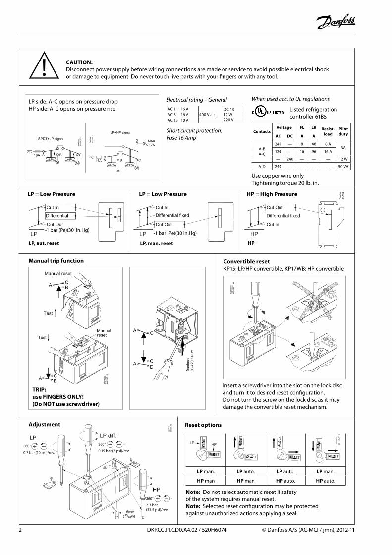
CAUTION:Disconnect power supply before wiring connections are made or service to avoid possible electrical shock or damage to equipment. Do never touch live parts with your fingers or with any tool.
-1 bar (Pe)(30 in.Hg)-1 bar (Pe)(30 in.Hg)
When used acc. to UL regulations
LP, aut. reset LP, man. reset HP
LP = Low Pressure LP = Low Pressure HP = High Pressure
LP side: A-C opens on pressure dropHP side: A-C opens on pressure rise AC 1 16 A
400 V a.c.DC 1312 W220 V
AC 3 16 AAC 15 10 A
Electrical rating – General
Short circuit protection: Fuse 16 Amp
ContactsVoltage FL LR Resist.
loadPilotdutyAC DC A A
A-BA-C
240 — 8 48 8 A3A
120 — 16 96 16 A
— 240 — — — 12 W
A-D 240 — — — — 50 VA
Use copper wire onlyTightening torque 20 lb. in.
Listed refrigerationcontroller 61B5
Manual trip function
Adjustment
Convertible resetKP15: LP/HP convertible, KP17WB: HP convertible
Insert a screwdriver into the slot on the lock disc and turn it to desired reset configuration. Do not turn the screw on the lock disc as it may damage the convertible reset mechanism.
LP man. LP auto. LP auto. LP man.
HP man HP man HP auto. HP auto.
Note: Do not select automatic reset if safety of the system requires manual reset.Note: Selected reset configuration may be protected against unauthorized actions applying a seal.
TRIP:use FINGERS ONLY! (Do NOT use screwdriver)
Reset options