Embed Size (px)
Citation preview
1
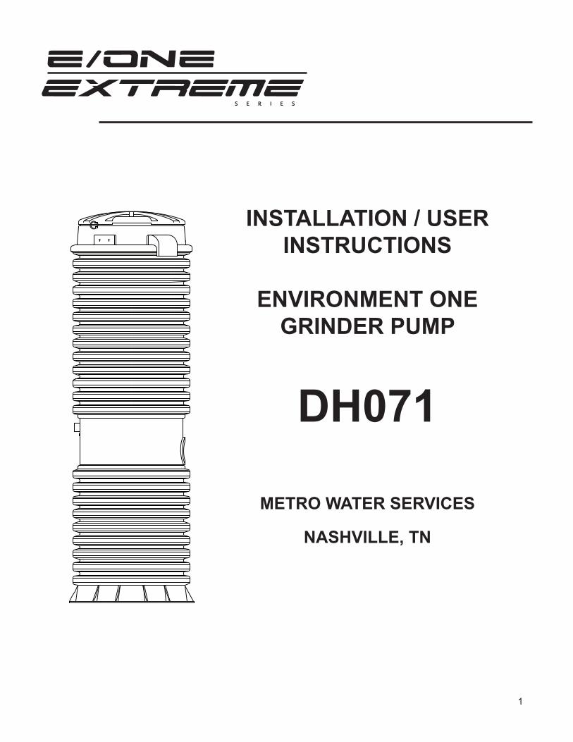
INSTALLATION / USER INSTRUCTIONS
ENVIRONMENT ONEGRINDER PUMP
DH071
METRO WATER SERVICES
NASHVILLE, TN
2
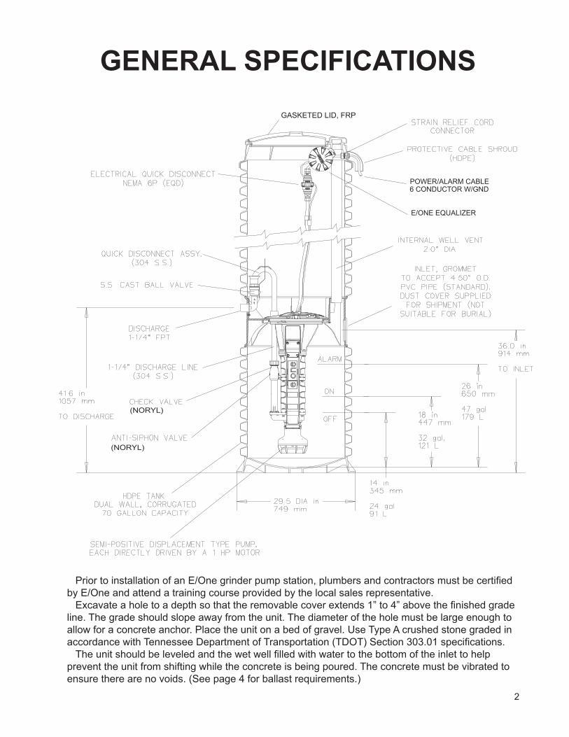
GENERAL SPECIFICATIONS
Prior to installation of an E/One grinder pump station, plumbers and contractors must be certified by E/One and attend a training course provided by the local sales representative.
Excavate a hole to a depth so that the removable cover extends 1” to 4” above the finished grade line. The grade should slope away from the unit. The diameter of the hole must be large enough to allow for a concrete anchor. Place the unit on a bed of gravel. Use Type A crushed stone graded in accordance with Tennessee Department of Transportation (TDOT) Section 303.01 specifications.
The unit should be leveled and the wet well filled with water to the bottom of the inlet to help prevent the unit from shifting while the concrete is being poured. The concrete must be vibrated to ensure there are no voids. (See page 4 for ballast requirements.)
3
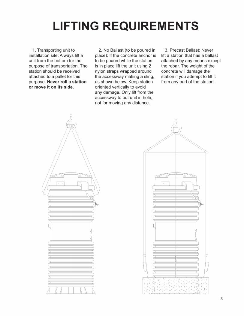
LIFTING REQUIREMENTS
1. Transporting unit to installation site: Always lift a unit from the bottom for the purpose of transportation. The station should be received attached to a pallet for this purpose. Never roll a station or move it on its side.
2. No Ballast (to be poured in place): If the concrete anchor is to be poured while the station is in place lift the unit using 2 nylon straps wrapped around the accessway making a sling, as shown below. Keep station oriented vertically to avoid any damage. Only lift from the accessway to put unit in hole, not for moving any distance.
3. Precast Ballast: Never lift a station that has a ballast attached by any means except the rebar. The weight of the concrete will damage the station if you attempt to lift it from any part of the station.
4
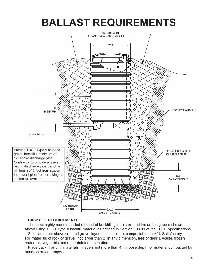
BALLAST REQUIREMENTS
BACKFILL REQUIREMENTS: The most highly recommended method of backfilling is to surround the unit to grades shown
above using TDOT Type A backfill material as defined in Section 303.01 of the TDOT specifications. Soil placement above crushed gravel layer shall be clean, compactable backfill. Satisfactory
soil materials of rock or gravel, not larger than 2” in any dimension, free of debris, waste, frozen materials, vegetable and other deleterious matter.
Place backfill and fill materials in layers not more than 4” in loose depth for material compacted by hand-operated tampers.
BALLAST HEIGHT
(405 LBS./2.7 CU FT)CONCRETE ANCHOR
BALLAST DIAMETER
FILL TO GRADE WITHCLEAN COMPACTABLE BACKFILL
UNDISTURBEDEARTH
TDOT TYPE A BACKFILL
Ø36.0
10.0
Ø26.4
MINIMUM12”
6’ MINIMUM
Provide TDOT Type A crushed gravel backfill a minimum of 12” above discharge pipe. Contractor to provide a gravel bed in discharge pipe trench a minimum of 6 feet from station to prevent pipe from breaking at station excavation.
5
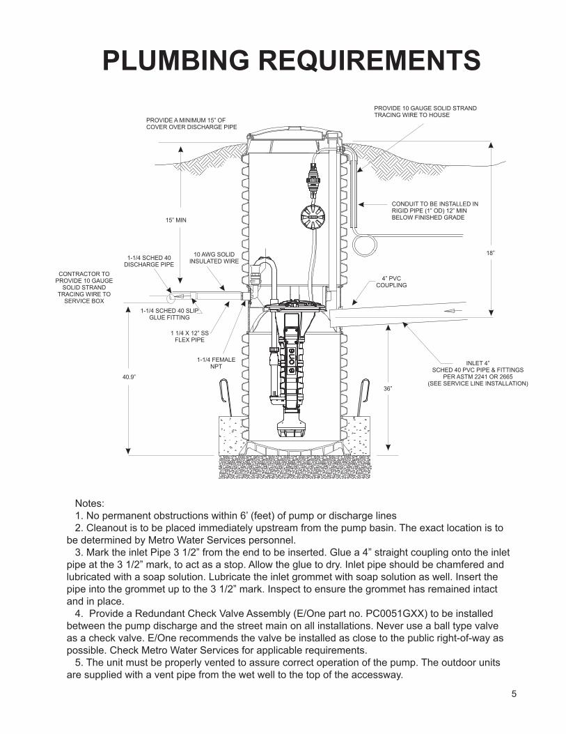
PLUMBING REQUIREMENTS
Notes:1. No permanent obstructions within 6’ (feet) of pump or discharge lines2. Cleanout is to be placed immediately upstream from the pump basin. The exact location is to
be determined by Metro Water Services personnel.3. Mark the inlet Pipe 3 1/2” from the end to be inserted. Glue a 4” straight coupling onto the inlet
pipe at the 3 1/2” mark, to act as a stop. Allow the glue to dry. Inlet pipe should be chamfered and lubricated with a soap solution. Lubricate the inlet grommet with soap solution as well. Insert the pipe into the grommet up to the 3 1/2” mark. Inspect to ensure the grommet has remained intact and in place.
4. Provide a Redundant Check Valve Assembly (E/One part no. PC0051GXX) to be installed between the pump discharge and the street main on all installations. Never use a ball type valve as a check valve. E/One recommends the valve be installed as close to the public right-of-way as possible. Check Metro Water Services for applicable requirements.
5. The unit must be properly vented to assure correct operation of the pump. The outdoor units are supplied with a vent pipe from the wet well to the top of the accessway.
6
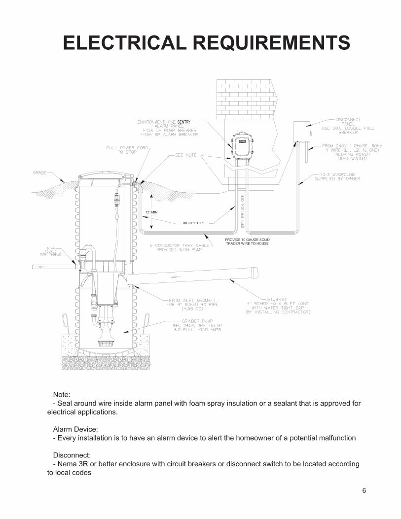
ELECTRICAL REQUIREMENTS
Note:- Seal around wire inside alarm panel with foam spray insulation or a sealant that is approved for
electrical applications.
Alarm Device:- Every installation is to have an alarm device to alert the homeowner of a potential malfunction
Disconnect:- Nema 3R or better enclosure with circuit breakers or disconnect switch to be located according
to local codes
7
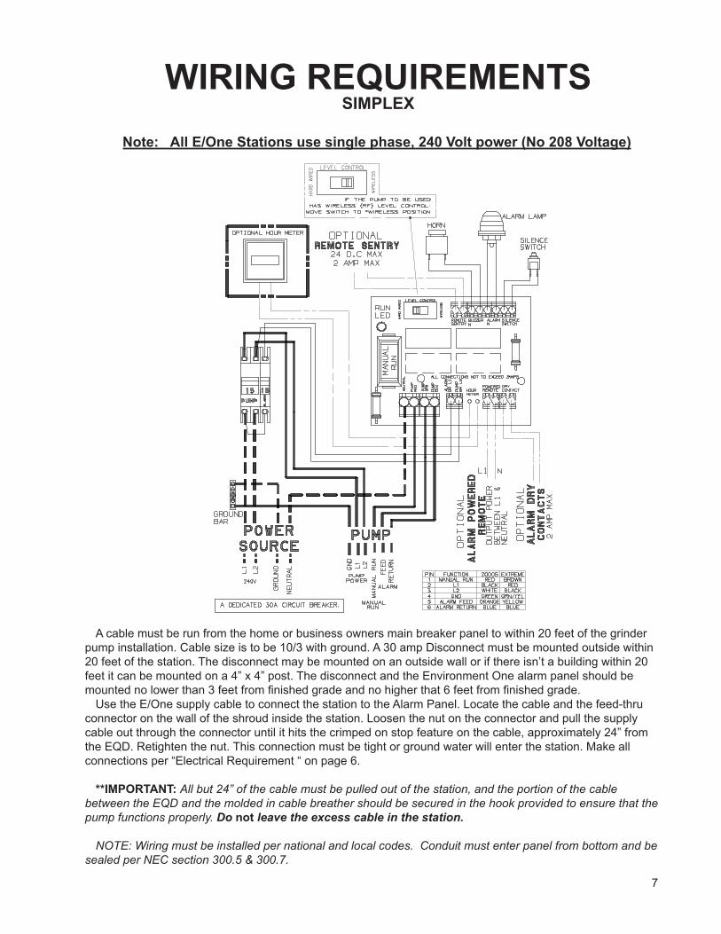
WIRING REQUIREMENTSSIMPLEX
Note: All E/One Stations use single phase, 240 Volt power (No 208 Voltage)
A cable must be run from the home or business owners main breaker panel to within 20 feet of the grinder pump installation. Cable size is to be 10/3 with ground. A 30 amp Disconnect must be mounted outside within 20 feet of the station. The disconnect may be mounted on an outside wall or if there isn’t a building within 20 feet it can be mounted on a 4” x 4” post. The disconnect and the Environment One alarm panel should be mounted no lower than 3 feet from finished grade and no higher that 6 feet from finished grade.
Use the E/One supply cable to connect the station to the Alarm Panel. Locate the cable and the feed-thru connector on the wall of the shroud inside the station. Loosen the nut on the connector and pull the supply cable out through the connector until it hits the crimped on stop feature on the cable, approximately 24” from the EQD. Retighten the nut. This connection must be tight or ground water will enter the station. Make all connections per “Electrical Requirement “ on page 6.
**IMPORTANT: All but 24” of the cable must be pulled out of the station, and the portion of the cable between the EQD and the molded in cable breather should be secured in the hook provided to ensure that the pump functions properly. Do not leave the excess cable in the station.
NOTE: Wiring must be installed per national and local codes. Conduit must enter panel from bottom and be
sealed per NEC section 300.5 & 300.7.
8
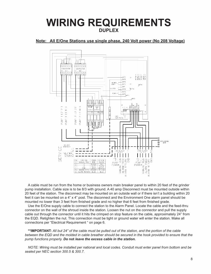
WIRING REQUIREMENTSDUPLEX
Note: All E/One Stations use single phase, 240 Volt power (No 208 Voltage)
A cable must be run from the home or business owners main breaker panel to within 20 feet of the grinder pump installation. Cable size is to be 8/3 with ground. A 40 amp Disconnect must be mounted outside within 20 feet of the station. The disconnect may be mounted on an outside wall or if there isn’t a building within 20 feet it can be mounted on a 4” x 4” post. The disconnect and the Environment One alarm panel should be mounted no lower than 3 feet from finished grade and no higher that 6 feet from finished grade.
Use the E/One supply cable to connect the station to the Alarm Panel. Locate the cable and the feed-thru connector on the wall of the shroud inside the station. Loosen the nut on the connector and pull the supply cable out through the connector until it hits the crimped on stop feature on the cable, approximately 24” from the EQD. Retighten the nut. This connection must be tight or ground water will enter the station. Make all connections per “Electrical Requirement “ on page 6.
**IMPORTANT: All but 24” of the cable must be pulled out of the station, and the portion of the cable between the EQD and the molded in cable breather should be secured in the hook provided to ensure that the pump functions properly. Do not leave the excess cable in the station.
NOTE: Wiring must be installed per national and local codes. Conduit must enter panel from bottom and be
sealed per NEC section 300.5 & 300.7.
9
DEBRIS REMOVAL: Prior to start-up test procedure, the core must be removed and the incoming sewer line flushed to force all miscellaneous debris into the tank. Next, all liquid and debris must be removed. Once tank is clean, re-install the pump and proceed with the test.
TEST PROCEDURE: When the system is complete and ready for use, the following steps should be taken to verify proper installation and operation:
a) Make sure that the discharge shutoff valve is fully open. This valve must not be closed when the pump is operating. In some installations there may be a valve, or valves, at the street main that must also be open.
b) Turn ON the alarm power circuit breaker.c) Fill tank with water until the alarm turns ON. Shut off water.d) Turn ON pump power circuit breaker; the pump should turn on immediately. Within one minute
the alarm will turn off. Within three minutes the pump will turn off.
Environment One Corporation2773 Balltown RoadNiskayuna, New York 12309–1090
Voice: (01) 518.346.6161Fax: 518.346.6188
www.eone.comNA0209P01
09/09
START-UP REQUIREMENTS
10
User Instructions for the Environment One Grinder PumpCongratulations on your Environment One grinder pump investment. With proper care and by following a few guidelines, your grinder pump will give you years of dependable service.
General InformationIn order to provide you with suitable wastewater disposal, your home is served by a low pressure sewer system. The key element in this system is an Environment One grinder pump. The tank collects all solid materials and effluent from the house. The solid materials are then ground to a small size suitable for pumping as a slurry with the effluent water. The grinder pump generates sufficient pressure to pump this slurry from your home to the wastewater treatment receiving line and/or disposal plant.
This device complies with Part 15 of the FCC rules. Operation is subject to the following two conditions: 1) this device may not cause harmful interference; and 2) this device must accept any interference received, including interference that may cause undesired operation. Any changes or modifications not expressly approved by the party responsible for compliance could void the user’s authority to operate this equipment.
Care and Use of your Grinder PumpThe Environment One grinder pump is capable of accepting and pumping a wide range of materials. Regulatory agencies advise that the following items should not be introduced into any sewer, either directly or through a kitchen waste disposal unit:
Glass Seafood shells Diapers, socks, rags or cloth
Metal Plastic objects (toys, utensils, etc.) Kitty litter
Goldfish stone Sanitary napkins or tampons
In addition, you must never introduce into any sewer:
Explosives Strong chemicals Lubricating oil and/or grease
Flammable material Gasoline
Periods of DisuseIf your home or building is left unoccupied for longer than a couple of weeks, perform the following procedure:
Purge the System. Run clean water into the unit until the pump activates. Immediately turn off the water and allow the grinder pump to run until it shuts off automatically.
Duplex Units. Special attention must be taken to ensure that both pumps turn on when clean water is added to the tank.
Caution: Do not disconnect power to the unit
Power FailureYour grinder pump cannot dispose of wastewater without electrical power. If electrical power service is interrupted, keep water usage to a minimum.
Pump Failure AlarmYour Environment One grinder pump has been manufactured to produce an alarm signal (120 volt) in the event of a high water level in the basin. The installer must see that the alarm signal provided is connected to an audible and/or visual alarm in such a manner as to provide adequate warning to the user that service is required. During the interim prior to the arrival of an authorized service technician, water usage must be limited to the reserve capacity of the tank.
For service, please call your local distributor: