Embed Size (px)
Citation preview
TE CONNECTIVITY SENSORS /// INSTALLATION | WIRING GUIDE 05/2016 Page 1
Contents Important Safety Instructions 2
Wiring Schematic 2
Cable Wiring
Standard & Conduit w/ Cable 3
Submersible Cable Wire 4
Connector Wiring
DIN (Form A, Form C) 5
Bendix™ (6 Pin, 4 Pin) 6
Packard™ Metri-Pack 150 7
Minifast™ and M12x1 8
DT04 DEUTSCH (6 Pin, 4 Pin) 9
Molex™ 10
Pressure + Temperature Transmitter Wiring
Cable or Wire (Pressure & Temp.) 11
DIN Connector (Pressure & Temperature) 12
Bendix™, M12 & DT04 DEUTSCH (Pressure & Temp.) 13
INSTALLATION | WIRING GUIDE AST Pressure Sensors
Hirschmann, Bendix, Metri-Pack, Minifast and Molex are trademarks of their respective owners.
INSTALLATION | WIRING GUIDE AST Pressure Sensors
TE CONNECTIVITY SENSORS /// INSTALLATION | WIRING GUIDE 05//2016 Page 2
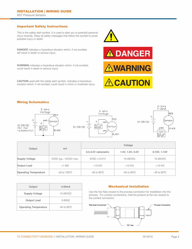
Important Safety Instructions
This is the safety alert symbol. It is used to alert you to potential personal injury hazards. Obey all safety messages that follow this symbol to avoid possible injury or death.
DANGER indicates a hazardous situation which, if not avoided, will result in death or serious injury.
WARNING indicates a hazardous situation which, if not avoided, could result in death or serious injury.
CAUTION used with the safety alert symbol, indicates a hazardous situation which, if not avoided, could result in minor or moderate injury.
Wiring Schematics
Output mV
Voltage
0.5-4.5V ratiometric 1-5V, 1-6V, 0-5V 0-10V, 1-10V
Supply Voltage 5VDC typ., 10VDC max. 5VDC ± 0.01V 10-28VDC 15-28VDC
Output Load >1 MΩ >10 KΩ >10 KΩ >10 KΩ
Operating Temperature -40 to 105ºC -40 to 85ºC -40 to 85ºC -40 to 85ºC
Output 4-20mA Mechanical Installation
Supply Voltage 10-28VDC Use the hex flats closest to the process connection for installation into the process. For conduit connections, hold the product at the hex closest to the conduit connection.
Output Load 0-800Ω
Operating Temperature -40 to 85ºC
INSTALLATION | WIRING GUIDE AST Pressure Sensors
TE CONNECTIVITY SENSORS /// INSTALLATION | WIRING GUIDE 05//2016 Page 3
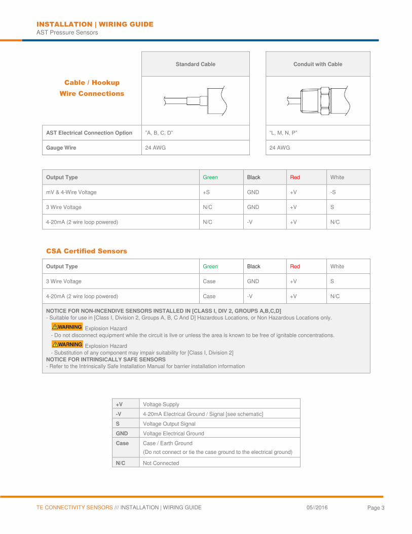
Cable / Hookup
Wire Connections
Standard Cable
Conduit with Cable
AST Electrical Connection Option ”A, B, C, D”
“L, M, N, P”
Gauge Wire 24 AWG
24 AWG
Output Type Green Black Red White
mV & 4-Wire Voltage +S GND +V -S
3 Wire Voltage N/C GND +V S
4-20mA (2 wire loop powered) N/C -V +V N/C
CSA Certified Sensors
Output Type Green Black Red White
3 Wire Voltage Case GND +V S
4-20mA (2 wire loop powered) Case -V +V N/C
NOTICE FOR NON-INCENDIVE SENSORS INSTALLED IN [CLASS I, DIV 2, GROUPS A,B,C,D]
- Suitable for use in [Class I, Division 2, Groups A, B, C And D] Hazardous Locations, or Non Hazardous Locations only.
Explosion Hazard - Do not disconnect equipment while the circuit is live or unless the area is known to be free of ignitable concentrations.
Explosion Hazard - Substitution of any component may impair suitability for [Class I, Division 2]
NOTICE FOR INTRINSICALLY SAFE SENSORS
- Refer to the Intrinsically Safe Installation Manual for barrier installation information
+V Voltage Supply
-V 4-20mA Electrical Ground / Signal [see schematic]
S Voltage Output Signal
GND Voltage Electrical Ground
Case Case / Earth Ground
(Do not connect or tie the case ground to the electrical ground)
N/C Not Connected
INSTALLATION | WIRING GUIDE AST Pressure Sensors
TE CONNECTIVITY SENSORS /// INSTALLATION | WIRING GUIDE 05//2016 Page 4
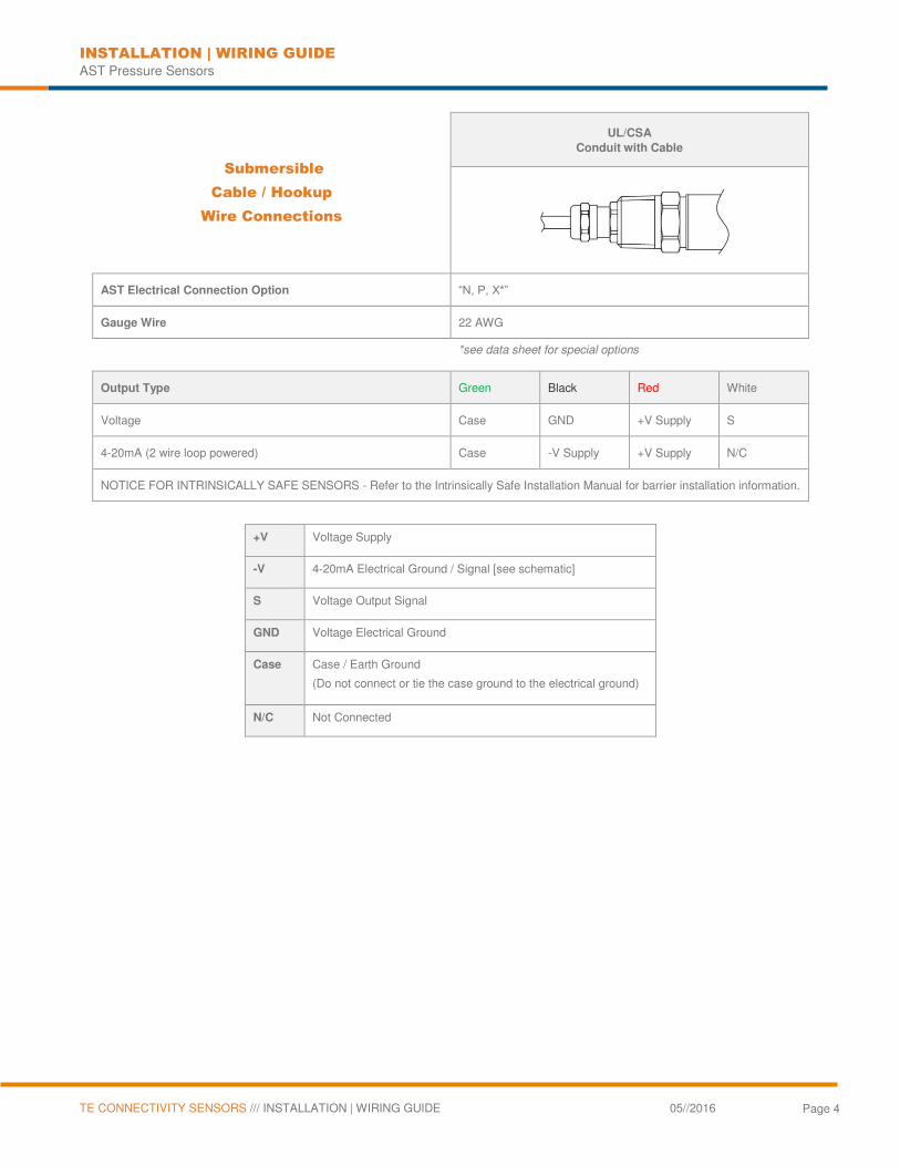
Submersible
Cable / Hookup
Wire Connections
UL/CSA
Conduit with Cable
AST Electrical Connection Option “N, P, X*”
Gauge Wire 22 AWG
*see data sheet for special options
Output Type Green Black Red White
Voltage Case GND +V Supply S
4-20mA (2 wire loop powered) Case -V Supply +V Supply N/C
NOTICE FOR INTRINSICALLY SAFE SENSORS - Refer to the Intrinsically Safe Installation Manual for barrier installation information.
+V Voltage Supply
-V 4-20mA Electrical Ground / Signal [see schematic]
S Voltage Output Signal
GND Voltage Electrical Ground
Case Case / Earth Ground
(Do not connect or tie the case ground to the electrical ground)
N/C Not Connected
INSTALLATION | WIRING GUIDE AST Pressure Sensors
TE CONNECTIVITY SENSORS /// INSTALLATION | WIRING GUIDE 05//2016 Page 5
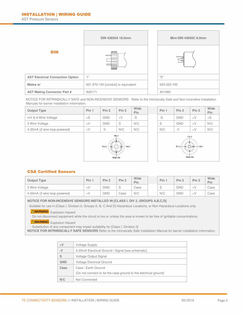
DIN
DIN 43650A 18.0mm
Mini-DIN 43650C 8.0mm
AST Electrical Connection Option “I” “E”
Mates w/ 931 970-100 [conduit] or equivalent
933 023-100
AST Mating Connector Part # A09171 A01980
NOTICE FOR INTRINSICALLY SAFE and NON-INCENDIVE SENSORS - Refer to the Intrinsically Safe and Non-Incendive Installation Manuals for barrier installation information.
Output Type Pin 1 Pin 2 Pin 3 Wide
Pin
Pin 1 Pin 2 Pin 3
Wide
Pin
mV & 4-Wire Voltage +S GND +V -S -S GND +V +S
3 Wire Voltage +V GND S N/C S GND +V N/C
4-20mA (2 wire loop powered) +V -V N/C N/C N/C -V +V N/C
CSA Certified Sensors
Output Type Pin 1 Pin 2 Pin 3 Wide
Pin
Pin 1 Pin 2 Pin 3
Wide
Pin
3 Wire Voltage +V GND S Case S GND +V Case
4-20mA (2 wire loop powered) +V GND Case N/C N/C GND +V Case
NOTICE FOR NON-INCENDIVE SENSORS INSTALLED IN [CLASS I, DIV 2, GROUPS A,B,C,D]
- Suitable for use in [Class I, Division 2, Groups A, B, C And D] Hazardous Locations, or Non Hazardous Locations only.
Explosion Hazard - Do not disconnect equipment while the circuit is live or unless the area is known to be free of ignitable concentrations.
Explosion Hazard - Substitution of any component may impair suitability for [Class I, Division 2]
NOTICE FOR INTRINSICALLY SAFE SENSORS Refer to the Intrinsically Safe Installation Manual for barrier installation information.
+V Voltage Supply
-V 4-20mA Electrical Ground / Signal [see schematic]
S Voltage Output Signal
GND Voltage Electrical Ground
Case Case / Earth Ground
(Do not connect or tie the case ground to the electrical ground)
N/C Not Connected
INSTALLATION | WIRING GUIDE AST Pressure Sensors
TE CONNECTIVITY SENSORS /// INSTALLATION | WIRING GUIDE 05//2016 Page 6
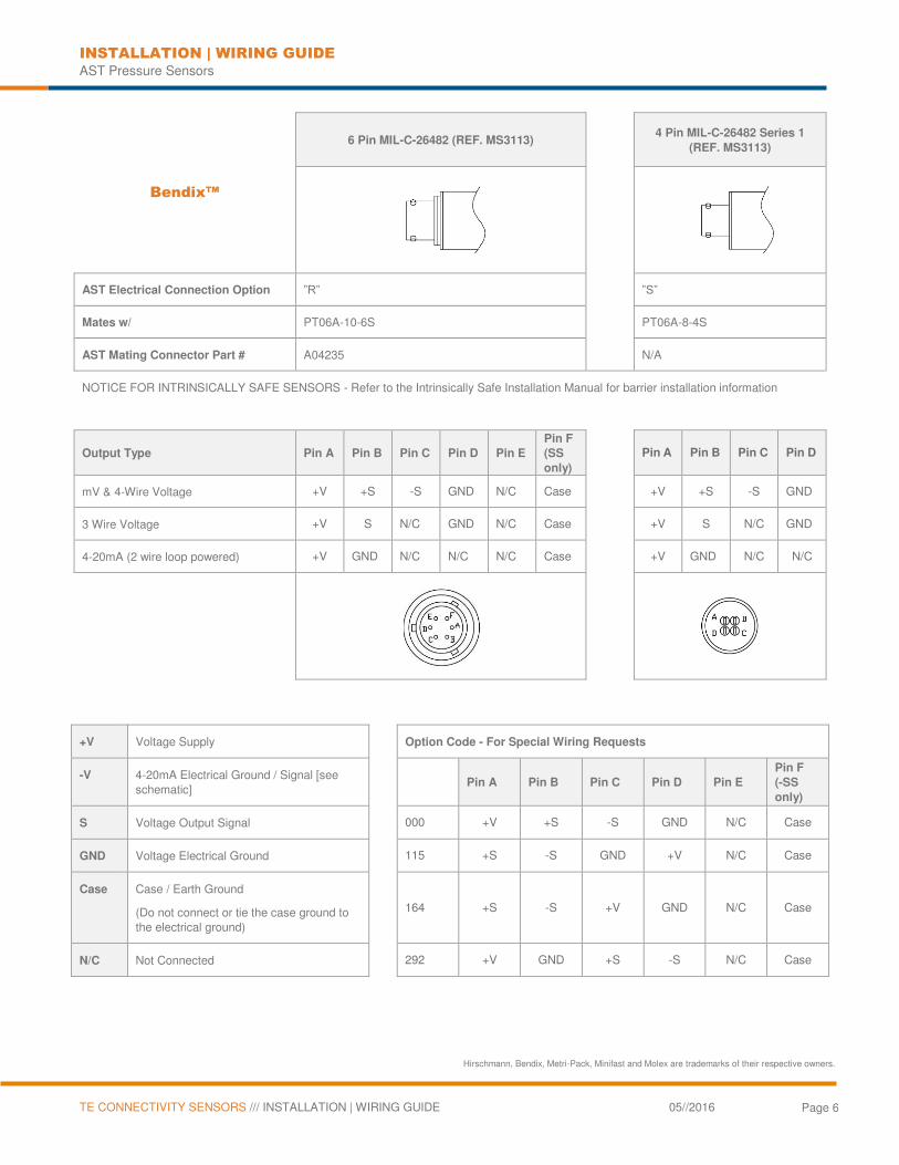
Bendix™
6 Pin MIL-C-26482 (REF. MS3113)
4 Pin MIL-C-26482 Series 1
(REF. MS3113)
AST Electrical Connection Option ”R”
”S”
Mates w/ PT06A-10-6S
PT06A-8-4S
AST Mating Connector Part # A04235
N/A
NOTICE FOR INTRINSICALLY SAFE SENSORS - Refer to the Intrinsically Safe Installation Manual for barrier installation information
Output Type Pin A Pin B Pin C Pin D Pin E
Pin F
(SS
only)
Pin A Pin B Pin C Pin D
mV & 4-Wire Voltage +V +S -S GND N/C Case +V +S -S GND
3 Wire Voltage +V S N/C GND N/C Case +V S N/C GND
4-20mA (2 wire loop powered) +V GND N/C N/C N/C Case +V GND N/C N/C
+V Voltage Supply Option Code - For Special Wiring Requests
-V 4-20mA Electrical Ground / Signal [see schematic]
Pin A Pin B Pin C Pin D Pin E
Pin F
(-SS
only)
S Voltage Output Signal 000 +V +S -S GND N/C Case
GND Voltage Electrical Ground 115 +S -S GND +V N/C Case
Case Case / Earth Ground
(Do not connect or tie the case ground to the electrical ground)
164 +S -S +V GND N/C Case
N/C Not Connected 292 +V GND +S -S N/C Case
Hirschmann, Bendix, Metri-Pack, Minifast and Molex are trademarks of their respective owners.
INSTALLATION | WIRING GUIDE AST Pressure Sensors
TE CONNECTIVITY SENSORS /// INSTALLATION | WIRING GUIDE 05//2016 Page 7
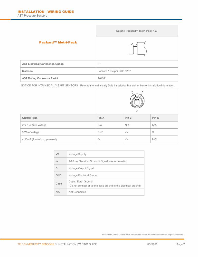
Packard™ Metri-Pack
Delphi: Packard™ Metri-Pack 150
AST Electrical Connection Option “F”
Mates w/ Packard™ Delphi 1206 5287
AST Mating Connector Part # A04391
NOTICE FOR INTRINSICALLY SAFE SENSORS - Refer to the Intrinsically Safe Installation Manual for barrier installation information.
Output Type Pin A Pin B Pin C
mV & 4-Wire Voltage N/A N/A N/A
3 Wire Voltage GND +V S
4-20mA (2 wire loop powered) -V +V N/C
+V Voltage Supply
-V 4-20mA Electrical Ground / Signal [see schematic]
S Voltage Output Signal
GND Voltage Electrical Ground
Case Case / Earth Ground
(Do not connect or tie the case ground to the electrical ground)
N/C Not Connected
Hirschmann, Bendix, Metri-Pack, Minifast and Molex are trademarks of their respective owners.
INSTALLATION | WIRING GUIDE AST Pressure Sensors
TE CONNECTIVITY SENSORS /// INSTALLATION | WIRING GUIDE 05//2016 Page 8
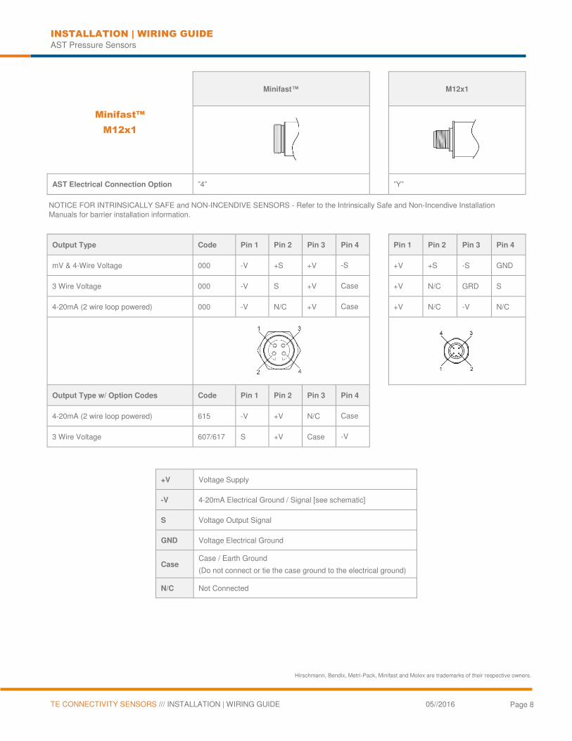
Minifast™
M12x1
Minifast™
M12x1
AST Electrical Connection Option ”4”
”Y”
NOTICE FOR INTRINSICALLY SAFE and NON-INCENDIVE SENSORS - Refer to the Intrinsically Safe and Non-Incendive Installation Manuals for barrier installation information.
Output Type Code Pin 1 Pin 2 Pin 3 Pin 4 Pin 1 Pin 2 Pin 3 Pin 4
mV & 4-Wire Voltage 000 -V +S +V -S +V +S -S GND
3 Wire Voltage 000 -V S +V Case +V N/C GRD S
4-20mA (2 wire loop powered) 000 -V N/C +V Case +V N/C -V N/C
Output Type w/ Option Codes Code Pin 1 Pin 2 Pin 3 Pin 4
4-20mA (2 wire loop powered) 615 -V +V N/C Case
3 Wire Voltage 607/617 S +V Case -V
+V Voltage Supply
-V 4-20mA Electrical Ground / Signal [see schematic]
S Voltage Output Signal
GND Voltage Electrical Ground
Case Case / Earth Ground
(Do not connect or tie the case ground to the electrical ground)
N/C Not Connected
Hirschmann, Bendix, Metri-Pack, Minifast and Molex are trademarks of their respective owners.
INSTALLATION | WIRING GUIDE AST Pressure Sensors
TE CONNECTIVITY SENSORS /// INSTALLATION | WIRING GUIDE 05//2016 Page 9
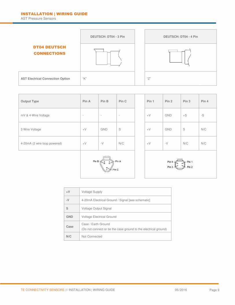
DT04 DEUTSCH
CONNECTIONS
DEUTSCH: DT04 - 3 Pin
DEUTSCH: DT04 - 4 Pin
AST Electrical Connection Option “K”
“Z”
Output Type Pin A Pin B Pin C
Pin 1 Pin 2 Pin 3 Pin 4
mV & 4-Wire Voltage - - -
+V GND +S -S
3 Wire Voltage +V GND S
+V GND S N/C
4-20mA (2 wire loop powered) +V -V N/C
+V -V N/C N/C
+V Voltage Supply
-V 4-20mA Electrical Ground / Signal [see schematic]
S Voltage Output Signal
GND Voltage Electrical Ground
Case Case / Earth Ground
(Do not connect or tie the case ground to the electrical ground)
N/C Not Connected
INSTALLATION | WIRING GUIDE AST Pressure Sensors
TE CONNECTIVITY SENSORS /// INSTALLATION | WIRING GUIDE 05//2016 Page 10
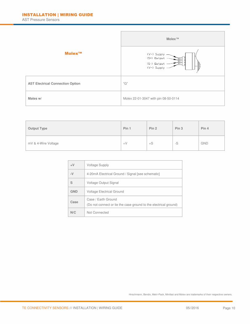
Molex™
Molex™
AST Electrical Connection Option “G”
Mates w/ Molex 22-01-3047 with pin 08-50-0114
Output Type Pin 1 Pin 2 Pin 3 Pin 4
mV & 4-Wire Voltage +V +S -S GND
+V Voltage Supply
-V 4-20mA Electrical Ground / Signal [see schematic]
S Voltage Output Signal
GND Voltage Electrical Ground
Case Case / Earth Ground
(Do not connect or tie the case ground to the electrical ground)
N/C Not Connected
Hirschmann, Bendix, Metri-Pack, Minifast and Molex are trademarks of their respective owners.

INSTALLATION | WIRING GUIDE AST Pressure Sensors
TE CONNECTIVITY SENSORS /// INSTALLATION | WIRING GUIDE 05//2016 Page 11
Pressure & Temperature
Cable / Hookup
Wire Connections
(AST20PT & AST45PT)
Cable
AST Electrical Connection Option ‘”A, B, C, D, L, M, N, P, X*”
Gauge Wire AST20PT- 24 AWG | AST45PT - 22 AWG
*see data sheet for special options
Output Type Green Black Red White
3 Wire Voltage Temp(out) -V(in) +V(in) Press(out)
4-20mA (2 wire loop powered)* +Temp -Press +Press -Temp
NOTICE FOR HAZARDOUS AREA SENSORS (AST46PT) - Refer to operating instructions for installation information.
* For units with loop-powered 4-20mA output, the pressure loop must be powered or the temperature output will not operate.
+V Voltage Supply
-V 4-20mA Electrical Ground / Signal [see schematic]
S Voltage Output Signal
GND Voltage Electrical Ground
Case Case / Earth Ground
(Do not connect or tie the case ground to the electrical ground)
N/C Not Connected
INSTALLATION | WIRING GUIDE AST Pressure Sensors
TE CONNECTIVITY SENSORS /// INSTALLATION | WIRING GUIDE 05//2016 Page 12
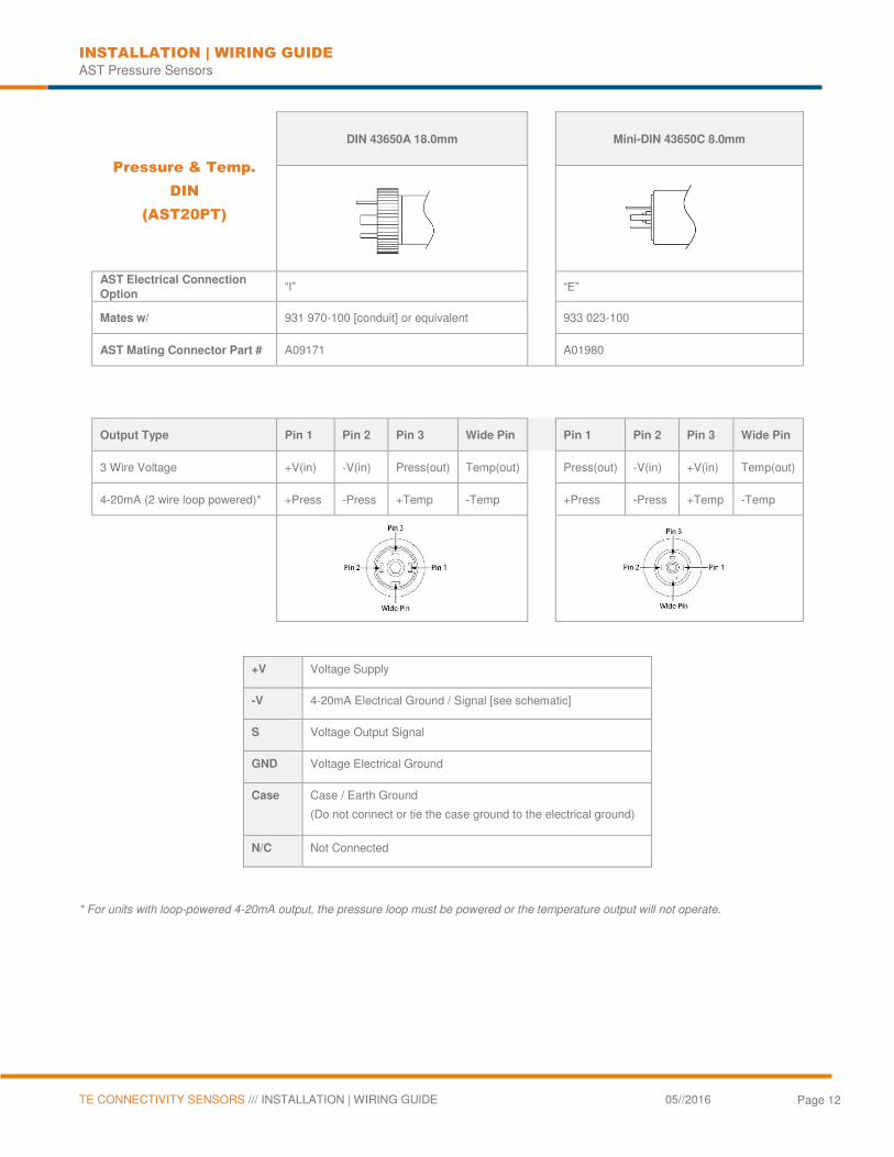
Pressure & Temp.
DIN
(AST20PT)
DIN 43650A 18.0mm
Mini-DIN 43650C 8.0mm
AST Electrical Connection
Option “I” “E”
Mates w/ 931 970-100 [conduit] or equivalent
933 023-100
AST Mating Connector Part # A09171
A01980
Output Type Pin 1 Pin 2 Pin 3 Wide Pin
Pin 1 Pin 2 Pin 3 Wide Pin
3 Wire Voltage +V(in) -V(in) Press(out) Temp(out)
Press(out) -V(in) +V(in) Temp(out)
4-20mA (2 wire loop powered)* +Press -Press +Temp -Temp
+Press -Press +Temp -Temp
+V Voltage Supply
-V 4-20mA Electrical Ground / Signal [see schematic]
S Voltage Output Signal
GND Voltage Electrical Ground
Case Case / Earth Ground
(Do not connect or tie the case ground to the electrical ground)
N/C Not Connected
* For units with loop-powered 4-20mA output, the pressure loop must be powered or the temperature output will not operate.
INSTALLATION | WIRING GUIDE AST Pressure Sensors
TE CONNECTIVITY SENSORS /// INSTALLATION | WIRING GUIDE 05//2016 Page 13
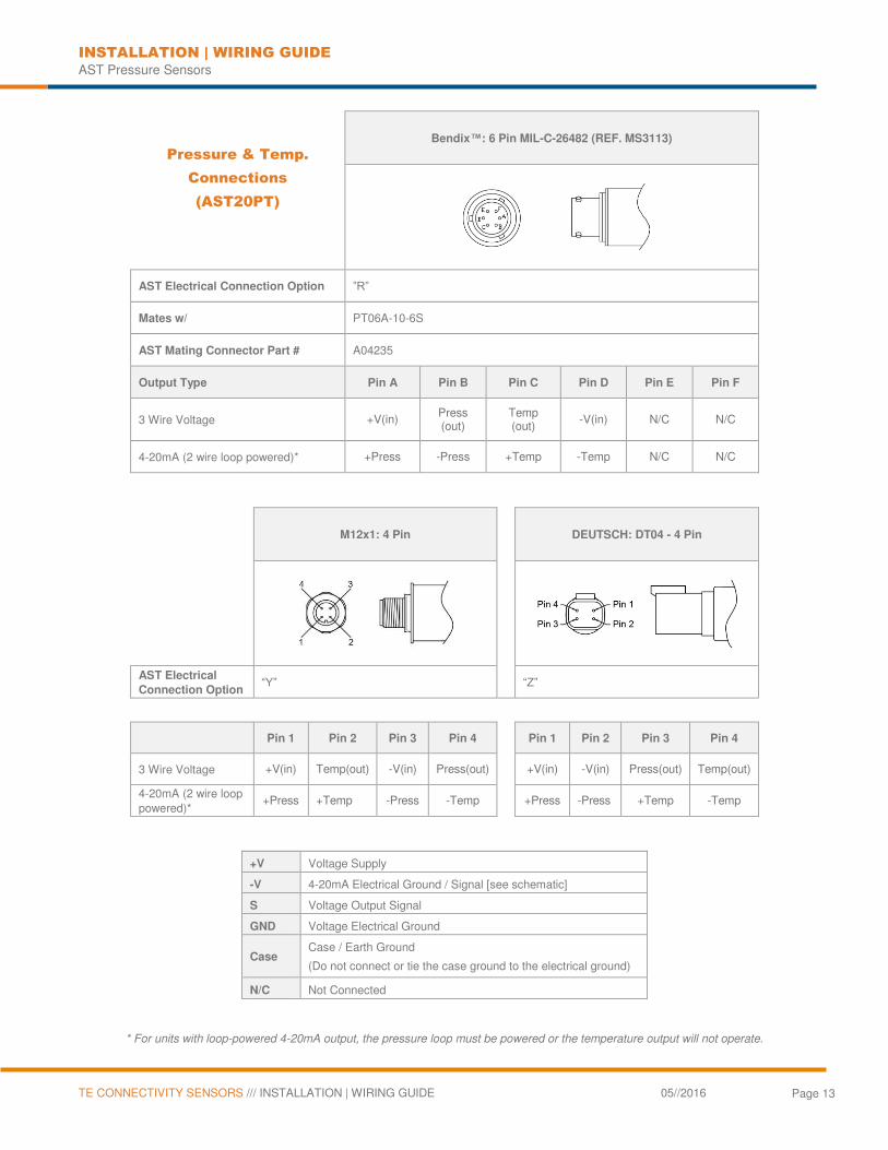
Pressure & Temp.
Connections
(AST20PT)
Bendix™: 6 Pin MIL-C-26482 (REF. MS3113)
AST Electrical Connection Option ”R”
Mates w/ PT06A-10-6S
AST Mating Connector Part # A04235
Output Type Pin A Pin B Pin C Pin D Pin E Pin F
3 Wire Voltage +V(in) Press (out)
Temp (out)
-V(in) N/C N/C
4-20mA (2 wire loop powered)* +Press -Press +Temp -Temp N/C N/C
M12x1: 4 Pin
DEUTSCH: DT04 - 4 Pin
AST Electrical
Connection Option “Y”
“Z”
Pin 1 Pin 2 Pin 3 Pin 4 Pin 1 Pin 2 Pin 3 Pin 4
3 Wire Voltage +V(in) Temp(out) -V(in) Press(out) +V(in) -V(in) Press(out) Temp(out)
4-20mA (2 wire loop powered)*
+Press +Temp -Press -Temp +Press -Press +Temp -Temp
+V Voltage Supply
-V 4-20mA Electrical Ground / Signal [see schematic]
S Voltage Output Signal
GND Voltage Electrical Ground
Case Case / Earth Ground
(Do not connect or tie the case ground to the electrical ground)
N/C Not Connected
* For units with loop-powered 4-20mA output, the pressure loop must be powered or the temperature output will not operate.
INSTALLATION | WIRING GUIDE AST Pressure Sensors
TE CONNECTIVITY SENSORS /// INSTALLATION | WIRING GUIDE 05//2016 Page 14
NORTH AMERICA
American Sensor Technologies, Inc. (AST), a TE Connectivity company 450 Clark Drive Mount Olive, NJ 07828 USA Tel +1 973 448 1901 Fax +1 973 448 1905 [email protected]
te.com/sensorsolutions
American Sensor Technologies, Inc. (AST), a TE Connectivity company.
AST, TE Connectivity, and TE connectivity (logo) are trademarks. All other logos, products and/or company names referred to herein might be trademarks of their respective owners.
The information given herein, including drawings, illustrations and schematics which are intended for illustration purposes only, is believed to be reliable. However, TE Connectivity makes no warranties as to its accuracy or completeness and disclaims any liability in connection with its use. TE Connectivity‘s obligations shall only be as set forth in TE Connectivity‘s Standard Terms and Conditions of Sale for this product and in no case will TE Connectivity be liable for any incidental, indirect or consequential damages arising out of the sale, resale, use or misuse of the product. Users of TE Connectivity products should make their own evaluation to determine the suitability of each such product for the specific application.
© 2016 TE Connectivity Ltd. family of companies All Rights Reserved.
Rev 00