Embed Size (px)
Citation preview
Curre
ntGua
rd™
CurrentGuard™
Surge Protective Devices
Installation,Operationand Maintenance ManualPN 750-0098-001
CurrentGuard™ and CurrentGuard™ Plus Installation, Operation and Maintenance Manual
®
™CurrentGuardPlus
Installation Assistance
Importance of Correct Installation
Warnings
Before Installation
System Configuration Verification
Environmental Condition Verification
Wiring Connection Diagram
Split-Phase, 3-Wire
3-Phase, 4-Wire WYE
3-Phase, 3-Wire DELTA
3-Phase, 4-Wire High-Leg DELTA
Conductor Routing
Upstream Over-Current Protection Device
Conductor Sizing
Mounting
Conduit Openings and Enclosure / Mounting Dimensions
Electrical Connections
Connecting Form C Dry Contacts
Verification and Power Up
Trouble Shooting
Technical Assistance
Return and Warranty Procedures
Warranty Statement
Table of Contents
CurrentGuard™ and CurrentGuard™ Plus Installation, Operation and Maintenance Manual 2
3
3
3
4
4
4
5-6
5
5
5
6
6
6
7
7
7-8
8
9
10
11
11
11
12
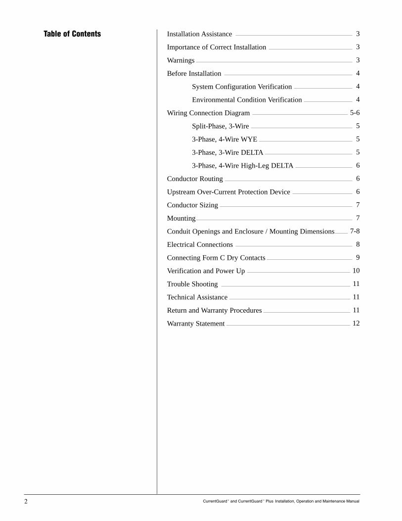
WARNING! HAZARDOUS VOLTAGES PRESENT Improperinstallation or misapplication may result in serious person-nel injury/or damage to electrical system. Read the com-plete installation instructions before proceeding with instal-lation. Remove all power to the electrical panel beforeinstalling or servicing the surge protective device (SPD).
W A R N I N G S !
Installation Assistance
The Importance of Correct Installation
Thank you for choosing the Current Technology® CurrentGuard™
series Surge Protective Device (SPD). We look forward to fulfill-ing your facility-wide surge protection needs.
Monday through Friday, 8:00 a.m. to 5:00 p.m. (EST) at800.238.5000.
This manual provides guidelines for the proper installation of theCurrentGuard family of devices. Proper product selection andcompliance with these guidelines will help your new suppressionsystem provide years of reliable service. If installers are unsureabout the facility electrical configuration or have other installa-tion-related questions, it is recommended they consult with a mas-ter electrician or other qualified electrical professional.
When shortcuts are taken or installation procedures are not fol-lowed, the CurrentGuard system may be damaged or may not pro-vide adequate protection. It is extremely important to follow theseinstallation procedures carefully.
CurrentGuard™ and CurrentGuard™ Plus Installation, Operation and Maintenance Manual 3
!
IMPORTANT SAFETY INSTRUCTIONS All work must be per-formed by licensed and qualified personnel. The electrical systemmust be properly grounded in accordance with the U.S. NationalElectrical Code, state and local codes or other applicable codes forthis SPD to function properly. Do not connect CurrentGuard deviceto the line side of the main service breaker or disconnecting means.This device is suitable for installation where the available short cir-cuit current is 200,000 rms symmetrical amperes up to 600VAC orless.
!
WARNING! The CurrentGuard™ warranty is voided if the unitis damaged as a result of improper installation or theinstaller’s failure to verify the following conditions prior toinstallation.
!
WARNING! Check to ensure that a proper bond is installedbetween neutral and ground at the transformer upstreamfrom all 3-phase WYE, 3-phase high leg DELTA or split-phaseCurrentGuard device (See NEC Article 250). If the trans-former is not accessible, check the main service discon-nect/panel for the N-G bond. Lack of a proper bond will dam-age CurrentGuard and void the warranty.
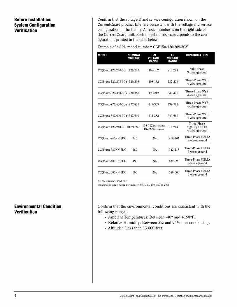
Confirm that the environmental conditions are consistent with thefollowing ranges:
• Ambient Temperatures: Between -40° and +158°F.• Relative Humidity: Between 5% and 95% non-condensing.• Altitude: Less than 13,000 feet.
Before Installation:System ConfigurationVerification
CurrentGuard™ and CurrentGuard™ Plus Installation, Operation and Maintenance Manual 4
MODEL NOMINAL L-N L-L CONFIGURATIONVOLTAGE VOLTAGE VOLTAGE
RANGE RANGE
CG(P)xxx-120/240-2G 120/240 108-132 216-264 Split-Phase3-wire+ground
CG(P)xxx-120/208-3GY 120/208 108-132 187-229 Three-Phase WYE4-wire+ground
CG(P)xxx-220/380-3GY 220/380 198-242 342-418 Three-Phase WYE4-wire+ground
CG(P)xxx-277/480-3GY 277/480 249-305 432-528 Three-Phase WYE4-wire+ground
CG(P)xxx-347/600-3GY 347/600 312-382 540-660 Three-Phase WYE4-wire+ground
Three-PhaseCG(P)xxx-120/240-3GHD120/240 108-132(A&C PHASES) 216-264 high-leg DELTA
187-229(B PHASES) 4-wire+ground
CG(P)xxx-240NN-3DG 240 NA 216-264 Three-Phase DELTA3-wire+ground
CG(P)xxx-380NN-3DG 380 NA 342-418 Three-Phase DELTA3-wire+ground
CG(P)xxx-480NN-3DG 480 NA 432-528 Three-Phase DELTA3-wire+ground
CG(P)xxx-600NN-3DG 600 NA 540-660 Three-Phase DELTA3-wire+ground
(P) for CurrentGuard Plusxxx denotes surge rating per mode (40, 60, 80, 100, 150 or 200)
Confirm that the voltage(s) and service configuration shown on theCurrentGuard product label are consistent with the voltage and serviceconfiguration of the facility. A model number is on the right side ofthe CurrentGuard unit. Each model number corresponds to the con-figurations printed in the table below:
Example of a SPD model number: CGP150-120/208-3GY
Environmental ConditionVerification
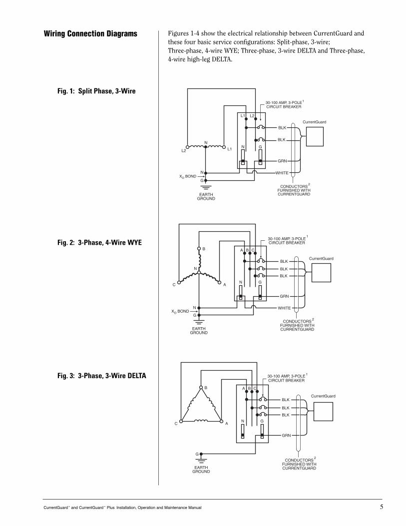
Figures 1-4 show the electrical relationship between CurrentGuard andthese four basic service configurations: Split-phase, 3-wire; Three-phase, 4-wire WYE; Three-phase, 3-wire DELTA and Three-phase, 4-wire high-leg DELTA.
Wiring Connection Diagrams
CurrentGuard™ and CurrentGuard™ Plus Installation, Operation and Maintenance Manual 5
2
L1
1
Fig. 1: Split Phase, 3-Wire
2
ORN
RED
1
Fig. 2: 3-Phase, 4-Wire WYE
ORN
RED
1
2
Fig. 3: 3-Phase, 3-Wire DELTA

Conductor Routing
CurrentGuard™ and CurrentGuard Plus™ Installation, Operation and Maintenance Manual 6
CAUTION: CurrentGuard’s performance will be limitedseverely if the conductors are (a) too long, (b) are of too smalla wire gauge, (c) have too many bends or (d) have sharpbends.
!
The factors listed above should be addressed during the design of aninstallation to reserve a suitable place for CurrentGuard next to itspoint of connection to the electrical system. The selected mountinglocation should allow for the shortest possible conductor runs and adirect route with a minimum of bends. If bends are required, theyshould be sweeping bends. Do not make sharp 90° bends for appear-ance purposes because they will severely decrease the effectiveness ofCurrentGuard.
Binding or twisting conductors together using tie-wraps or electricaltape increases the protection performance of the device.
G
RED
1
2
Fig. 4: 3-Phase, 4-Wire High-Leg DELTA
1. Optional – All CurrentGuard Plus units can be connected without an upstream breaker/fuse.
2. Applies to 40, 60 and 80 kA units only.
Upstream Over-CurrentProtection Device
All CurrentGuard series units must be connected in parallel with theelectrical system. CurrentGuard units have built-in over-current fusingrated up to 200,000 rms symmetrical ampere at 600VAC and can beconnected directly to the electrical distribution system bus without anupstream over-current protection device (OCPD). However, the use ofan external OCPD is recommended.
If the SPD is connected to a dedicated overcurrent protection device, a60A breaker is recommended (30A minimum, 200A maximum). Theadvantage of using a dedicated over-current device for the SPD (even ifthe upstream breaker is 200A or less) is that it allows the SPD to be de-energized during service without disturbing the electrical service tothe rest of the facility.
CurrentGuard™ and CurrentGuard™ Plus Installation, Operation and Maintenance Manual 7
Mount the CurrentGuard to the building structure using constructionmethods and hardware appropriate for your site. Install the conduitand pull the conductors as specified above or according to the engi-neer’s design.
If desired, punch holes at this time for the conduit or nipple or waituntil the CurrentGuard is mounted to the building structure. Punchholes only in the shaded areas as shown in the following illustration.
Mounting
Conduit Openings
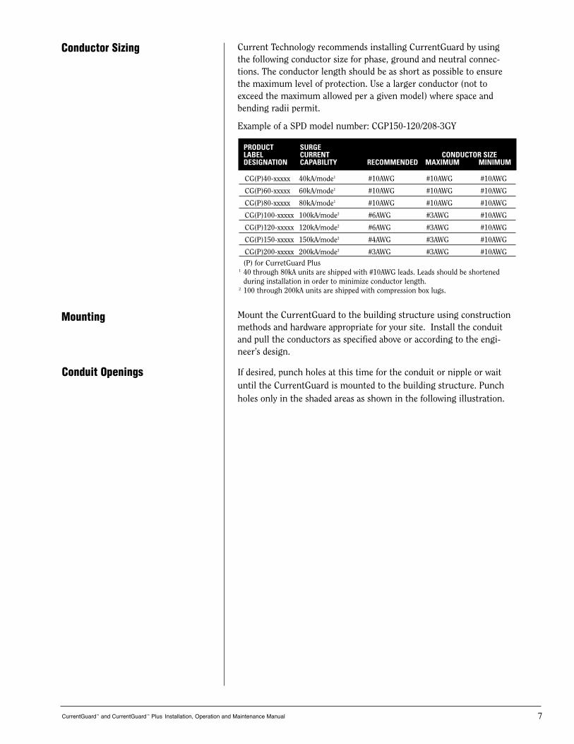
Conductor Sizing Current Technology recommends installing CurrentGuard by usingthe following conductor size for phase, ground and neutral connec-tions. The conductor length should be as short as possible to ensurethe maximum level of protection. Use a larger conductor (not toexceed the maximum allowed per a given model) where space andbending radii permit.
Example of a SPD model number: CGP150-120/208-3GY
PRODUCT SURGE LABEL CURRENT CONDUCTOR SIZEDESIGNATION CAPABILITY RECOMMENDED MAXIMUM MINIMUM
CG(P)40-xxxxx 40kA/mode1 #10AWG #10AWG #10AWG
CG(P)60-xxxxx 60kA/mode1 #10AWG #10AWG #10AWG
CG(P)80-xxxxx 80kA/mode1 #10AWG #10AWG #10AWG
CG(P)100-xxxxx 100kA/mode2 #6AWG #3AWG #10AWG
CG(P)120-xxxxx 120kA/mode2 #6AWG #3AWG #10AWG
CG(P)150-xxxxx 150kA/mode2 #4AWG #3AWG #10AWG
CG(P)200-xxxxx 200kA/mode2 #3AWG #3AWG #10AWG
(P) for CurretGuard Plus1 40 through 80kA units are shipped with #10AWG leads. Leads should be shortened
during installation in order to minimize conductor length.2 100 through 200kA units are shipped with compression box lugs.
Electrical Connections
CurrentGuard™ and CurrentGuard™ Plus Installation, Operation and Maintenance Manual 8
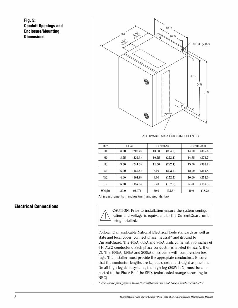
Following all applicable National Electrical Code standards as well asstate and local codes, connect phase, neutral* and ground toCurrentGuard. The 40kA, 60kA and 80kA units come with 36 inches of#10 AWG conductors. Each phase conductor is labeled (Phase A, B orC). The 100kA, 150kA and 200kA units come with compression boxlugs. The installer must provide the appropiate conductors. Ensurethat the conductor lengths are kept as short and straight as possible.On all high-leg delta systems, the high-leg (208V L-N) must be con-nected to the Phase B of the SPD. (color-coded orange according toNEC)* The 3-wire plus ground Delta CurrentGuard does not have a neutral conductor.
CAUTION: Prior to installation ensure the system configu-ration and voltage is equivalent to the CurrentGuard unitbeing installed.
!
Fig. 5:Conduit Openings and Enclosure/MountingDimensions
(D)(W2)
(H1)
(H2)
(H3)
ø0.31 (7.87)
(W1)
1.36"
(34.5mm)
3.20"
(83.8mm)
ALLOWABLE AREA FOR CONDUIT ENTRY
Dim CG40 CGx60-80 CGP100-200
H1 8.00 (203.2) 10.00 (254.0) 14.00 (355.6)
H2 8.75 (222.3) 10.75 (273.1) 14.75 (374.7)
H3 9.50 (241.3) 11.50 (292.1) 15.50 (393.7)
W1 6.00 (152.4) 8.00 (203.2) 12.00 (304.8)
W2 4.00 (101.6) 6.00 (152.4) 10.00 (254.0)
D 6.20 (157.5) 6.20 (157.5) 6.20 (157.5)
Weight 20.0 (9.07) 30.0 (13.6) 40.0 (18.2)
All measurements in inches (mm) and pounds (kg)
CurrentGuard™ and CurrentGuard™ Plus Installation, Operation and Maintenance Manual 9
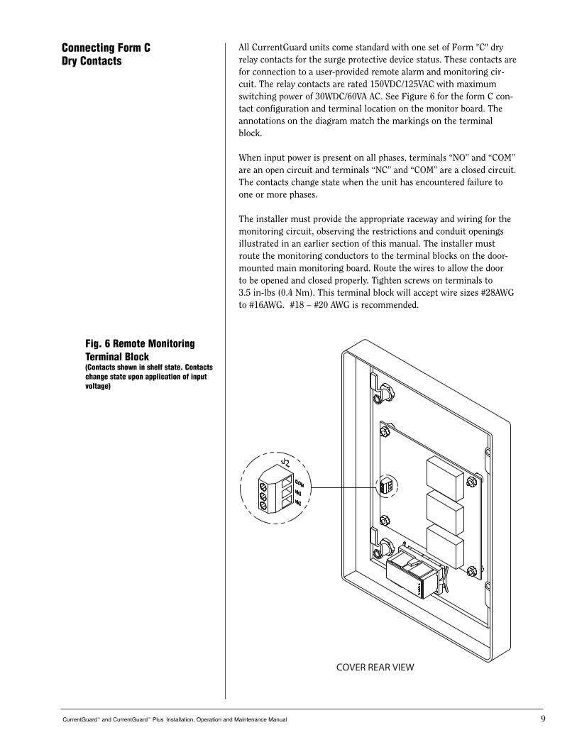
Connecting Form CDry Contacts
Fig. 6 Remote MonitoringTerminal Block (Contacts shown in shelf state. Contactschange state upon application of inputvoltage)
COVER REAR VIEW
All CurrentGuard units come standard with one set of Form "C" dryrelay contacts for the surge protective device status. These contacts arefor connection to a user-provided remote alarm and monitoring cir-cuit. The relay contacts are rated 150VDC/125VAC with maximumswitching power of 30WDC/60VA AC. See Figure 6 for the form C con-tact configuration and terminal location on the monitor board. Theannotations on the diagram match the markings on the terminalblock.
When input power is present on all phases, terminals “NO” and “COM”are an open circuit and terminals “NC” and “COM” are a closed circuit.The contacts change state when the unit has encountered failure toone or more phases.
The installer must provide the appropriate raceway and wiring for themonitoring circuit, observing the restrictions and conduit openingsillustrated in an earlier section of this manual. The installer mustroute the monitoring conductors to the terminal blocks on the door-mounted main monitoring board. Route the wires to allow the door to be opened and closed properly. Tighten screws on terminals to 3.5 in-lbs (0.4 Nm). This terminal block will accept wire sizes #28AWGto #16AWG. #18 – #20 AWG is recommended.
Verification and Power Up
CurrentGuard™ and CurrentGuard™ Plus Installation, Operation and Maintenance Manual 10
Apply power to CurrentGuard by closing the over current protectiondevice or switch feeding the suppressor.
WARNING: It is recommended that the cover of theCurrentGuard unit along with its associated cabling beinstalled prior to applying power. The monitoring harness,which exits the epoxy and connects to J2 on the monitor board, contains line voltage when power isapplied to the unit.
!
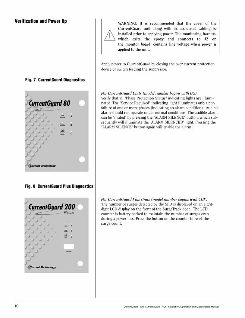
For CurrentGuard Units (model number begins with CG)Verify that all "Phase Protection Status" indicating lights are illumi-nated. The "Service Required" indicating light illuminates only uponfailure of one or more phases (indicating an alarm condition). Audiblealarm should not operate under normal conditions. The audible alarmcan be "muted" by pressing the "ALARM SILENCE" button, which sub-sequently will illuminate the "ALARM SILENCED" light. Pressing the"ALARM SILENCE" button again will enable the alarm.
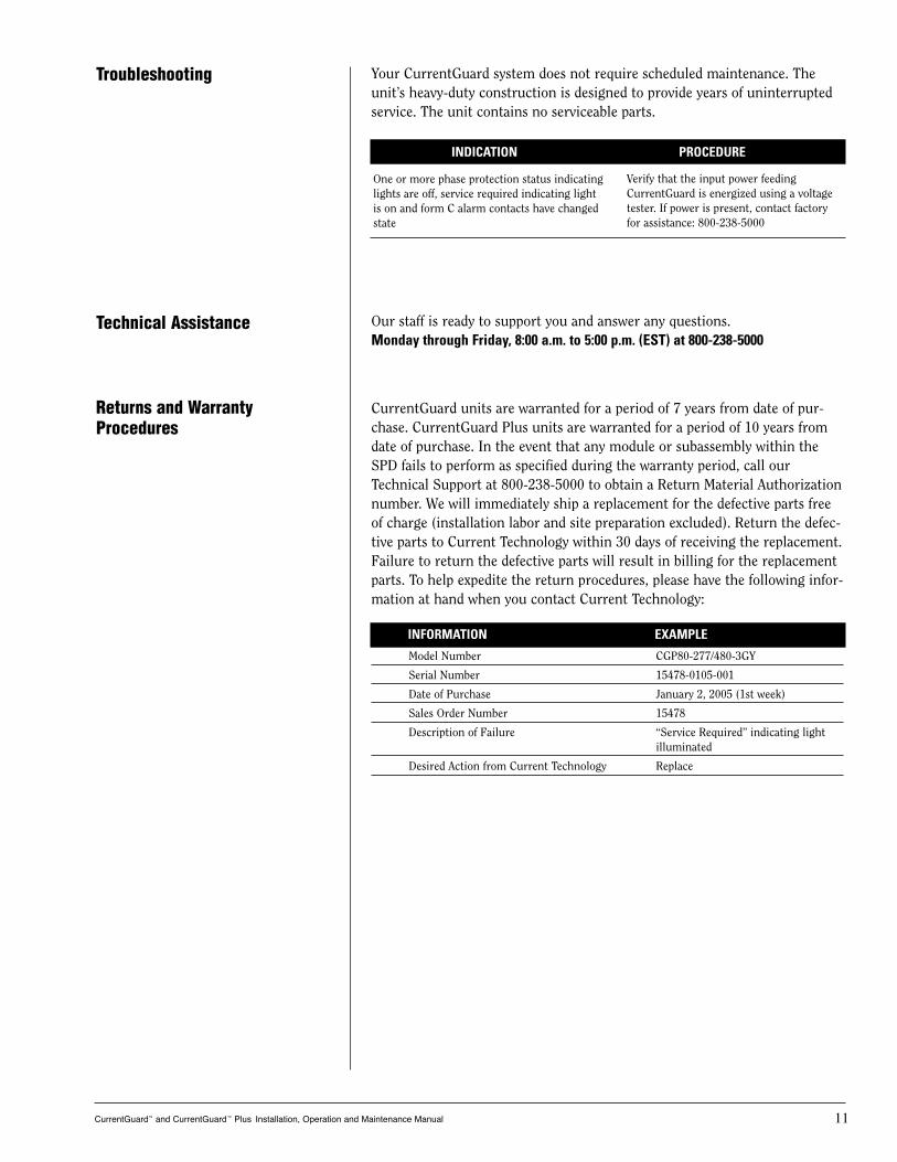
For CurrentGuard Plus Units (model number begins with CGP)The number of surges detected by the SPD is displayed on an eight-digit LCD display on the front of the SurgeTrack door. The LCDcounter is battery backed to maintain the number of surges even during a power loss. Press the button on the counter to reset thesurge count.
Fig. 7 CurrentGuard Diagnostics
Fig. 8 CurrentGuard Plus Diagnostics
CurrentGuard™ and CurrentGuard™ Plus Installation, Operation and Maintenance Manual 11
Troubleshooting
Technical Assistance
Your CurrentGuard system does not require scheduled maintenance. Theunit’s heavy-duty construction is designed to provide years of uninterruptedservice. The unit contains no serviceable parts.
Our staff is ready to support you and answer any questions.Monday through Friday, 8:00 a.m. to 5:00 p.m. (EST) at 800-238-5000
CurrentGuard units are warranted for a period of 7 years from date of pur-chase. CurrentGuard Plus units are warranted for a period of 10 years fromdate of purchase. In the event that any module or subassembly within theSPD fails to perform as specified during the warranty period, call ourTechnical Support at 800-238-5000 to obtain a Return Material Authorizationnumber. We will immediately ship a replacement for the defective parts freeof charge (installation labor and site preparation excluded). Return the defec-tive parts to Current Technology within 30 days of receiving the replacement.Failure to return the defective parts will result in billing for the replacementparts. To help expedite the return procedures, please have the following infor-mation at hand when you contact Current Technology:
One or more phase protection status indicatinglights are off, service required indicating lightis on and form C alarm contacts have changedstate
Verify that the input power feeding CurrentGuard is energized using a voltagetester. If power is present, contact factoryfor assistance: 800-238-5000
INDICATION PROCEDURE
Returns and WarrantyProcedures
INFORMATION EXAMPLE
Model Number CGP80-277/480-3GY
Serial Number 15478-0105-001
Date of Purchase January 2, 2005 (1st week)
Sales Order Number 15478
Description of Failure “Service Required” indicating light illuminated
Desired Action from Current Technology Replace
CurrentGuard™ and CurrentGuard™ Plus Installation, Operation and Maintenance Manual 12
Ten-Year Limited Warranty Danaher Power Solutions warrants that CurrentGuard andCurrentGuard Plus surge protective device (the "Product"), shall meetapplicable industry standards and specifications and be free fromdefects in materials and/or workmanship. Should any failure of theProduct to conform to this warranty appear within the warranty peri-od, Danaher Power Solutions shall either repair or replace the defec-tive Product, or part thereof, upon return to Danaher Power Solutionsmanufacturing facility in Richmond, Virginia with transportationcharges prepaid. The applicable warranty period is outlined below inthe warranty period section.
Danaher Power Solutions shall have no liability under this warranty for any problems or defects directly or indirectly caused bymisuse of the Product, alteration of the Product (including removal ofany warning labels), accidents, or improper installation, application,operation, or repair of the Product.
THIS WARRANTY REPRESENTS THE ENTIRE WARRANTY OFDANAHER POWER SOLUTIONS. ALL OTHER WARRANTIES, EXPRESS OR IMPLIED, ORAL OR WRITTEN, INCLUDING, BUT NOT LIMITED TO, THE WARRANTIESOF MERCHANTABILITY AND FITNESS FOR A PARTICULAR PUR-POSE ARE HEREBY DISCLAIMED.
The liability of Danaher Power Solutions under this warranty isexpressly limited to the replacement or repair of the defective partthereof, at Danaher Power Solutions sole option.
IN NO EVENT SHALL DANAHER POWER SOLUTIONSBE LIABLE FOR SPECIAL, INCIDENTAL, OR CONSEQUENTIAL DAM-AGES OF ANY KIND OR CHARACTER, NOR SHALL DANAHERPOWER SOLUTIONS’ LIABILTY EVER EXCEED THE PURCHASEPRICE PAID FOR SUCH DEFECTIVE PRODUCT.
This warranty is not transferable and may only be enforced by the solepurchaser. Claims under this warranty must be submitted to DanaherPower Solutions within thirty (30) days of discovery of anyCurrentGuard product defect.
Warranty PeriodCurrentGuard™ 7 Years from original date of purchaseCurrentGuard™ Plus 10 Years from original date of purchase
®
Tel: 804.236.3300800.238.5000
Current Technology TVSS ProductsBy Danaher Power Solutions5900 Eastport BoulevardRichmond, VA 23231-4453
©2005 Danaher Power Solutions. Current Technology®, CurrentGuard™ and CurrentGuard™ Plus are trademarks of Danaher Power Solutions. Printed in U.S.A. All Rights Reserved. PN 750-0098-001 2.22.05