Embed Size (px)
Citation preview
2S/1M - 4S/2M PLC Select Anti-Lock Braking Systems (L30041)
haldex.com
PLC Select 1M -FFABS
PLC Select 2M -FFABS
INSTALLATION/SERVICE GUIDE
2-Port ABSRelay Valve
6-Port ABSRelay Valve
Important Notice
The products described within this literature, including without limitation, product features, specifications,designs, availability and pricing are subject to change by Haldex and its subsidiaries at any time without notice.
This document and other information from Haldex, its subsidiaries and authorized distributors provide product and/or system options for further investigation by users having technical expertise. It is important that you analyze all aspects of your application and review the information concerning the product or system, in the current literature or catalog. Due to the variety of operating conditions and applications for these products or systems, the user, through their own analysis and testing, is solely responsible for making the final selection of the products and systems and assuring that all performance, safety and warning requirements are met.
PLC Select 1M & Page 1
If you have any questions on this product or any of the Innovative Products offered by Haldex, contact your local distributor for complete details. Technical Service or Troubleshooting help can be obtained by calling Haldex Technical Services Department at 800-643-2374, OPTION 2.
Section PageTable of Contents ................................................................ ....................................... 1 Important Notices ................................................. ..................................................... 2Wheel End Installation ........................................................ ....................................... 32S/1M Axle-By-Axle Configuration - Multi-Axle Trailers (2-6 Port Valve) .................42S/2M Side-By-Side Configuration - Multi-Axle Trailers (2-6 Port Valve) ..................54S/2M Side-By-Side Configuration - Multi-Axle Trailers ............................................64S/2M Side-By-Side Configuration - Multi-Axle Trailers With Lift Axle(s) ................74S/2M Axle-By-Axle Configuration - Multi-Axle Trailers ............................................84S/2M Axle-By-Axle Configuration - Multi-Axle Trailers With Lift Axle(s) ................9PLC Select 1M System Components ............................................................................10PLC Select 2M System Components ............................................................................11PLC Select 1M FFABS Valve Overview ............................. ..........................................12PLC Select 2M FFABS Valve Overview ............................. ..........................................13PLC Select 1M 6-Port ABS Relay Valve - Overview ............................. ......................14PLC Select 1M 2-Port ABS Relay Valve Overview ............................. .........................15 PLC Select 1M/2M Trailer Brake Control Valve (TBCV) Overview ................... .........16PLC Select 1M/2M FFABS Valve Typical Tank Mounting Overview....... ...................17PLC Select 1M ECU Power and Speed Sensor Connections .......... ...........................18PLSC Select 1M Pin Out for ABS Power Cord .............................................................18PLC Select 1M/2M Speed Sensor Cable Routing ............... ........................................19PLC Select 2M ECU Power and Speed Sensor Connections............................... ........20Notes Page................................... ................................................................................21PLC Select 1M/2M Chassis End of Line Testing ................. ........................................22PLC Select 1M/2M Road Testing ........................................ ........................................23PLC Select 1M/2M Diagnostic Tools .................................. ..................................... 24 - 26PLC Select 1M/2M Blink Code Diagnostics ......................... ................................... 27 - 31PLC Select 1M/2M Tire Scale Factor Chart ........................ .........................................32PLC Select 1M/2M Troubleshooting ABS Warning Light ................ .........................33PLC Select 1M/2M Troubleshooting Diagnostic Codes ................... ...................... 34 - 38SAE J1587/J1708 Fault Codes .............................................. ................................... 39 - 41PLC Select 1M/2M Valve Solenoids ................................................... .........................42Technical Support........................................... .............................................................43
Available For Download At haldex.comL20243 - ABS Service Components CatalogL30041 - 2S/1M - 4S/2M PLC Select Anti-Lock Braking SystemsL31154W - PC Diagnostic Instruction Manual (Web Only)L31158W - Info Center Instruction Manual (Web Only)
©2020 All Rights Reserved
Material may only be reproduced with the written permission of Haldex.
2S/1M - 4S/2M PLC Select L30041 Anti-Lock Braking Systems
Table of Contents
haldex.com 1
Safety First
This installation manual describes the correct installation procedures for the Haldex PLC Select 1M and 2M for Trailers/Dollies. The PLC Select 1M and 2M may be used with either drum or disc brakes. Care must be taken during each phase of the installation in order to ensure the system is installed correctly.
Please follow your company’s safety procedures at all times when installing this equipment. Be sure that you understand all instructions before you begin.
Remove all air pressure and electrical power from the brake system before beginning work.
Information Included In This Manual
The data listed herein is correct to the best of Haldex’s knowledge and belief, having been compiled from reliable and official sources of information. However, HALDEX CAN NOT ASSUME ANY RESPONSIBILITY for possible error or misapplication of the product. Final determination of the suitability of the products for the use contemplated by the Buyer is the sole responsibility of the Buyer. Haldex shall have no responsibility in connection with the suitability.
The description and specifications contained in this Installation/Service Manual are current at the time of printing. Haldex Brake Products Corporation reserves the right to discontinue or modify its models and/or procedures and to change specifications at any time without notice.
Important Notices
2 haldex.com
2S/1M - 4S/2M PLC Select L30041 Anti-Lock Braking Systems
Exciter RingSensor Block isnormally welded toaxle housing
AxleSensor Blocks (7)
9 o’clock 3 o’clock
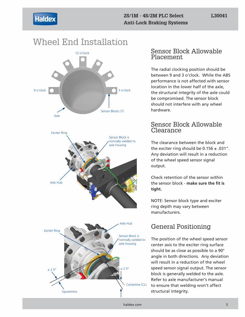
12 o’clock Sensor Block Allowable Placement
The radial clocking position should be between 9 and 3 o’clock. While the ABS performance is not affected with sensor location in the lower half of the axle, the structural integrity of the axle could be compromised. The sensor block should not interfere with any wheel hardware.
Sensor Block Allowable Clearance
The clearance between the block and the exciter ring should be 0.156 ± .031”. Any deviation will result in a reduction of the wheel speed sensor signal output.
Check retention of the sensor within the sensor block - make sure the fit is tight.
NOTE: Sensor block type and exciter ring depth may vary between manufacturers.
Wheel End Installation
PLC Select 1M & Page 1
2S/1M - 4S/2M PLC Select L30041 Anti-Lock Braking Systems
haldex.com 3
General Positioning
The position of the wheel speed sensor center axis to the exciter ring surface should be as close as possible to a 90° angle in both directions. Any deviation will result in a reduction of the wheel speed sensor signal output. The sensor block is generally welded to the axle. Refer to axle manufacturer’s manual to ensure that welding won’t affect structural integrity.
Axle Hub
Sensor Block isnormally welded toaxle housing
Axle Hub
Exciter Ring
Squareness
± 2.5°
Centerline (CL)
± 2.5°
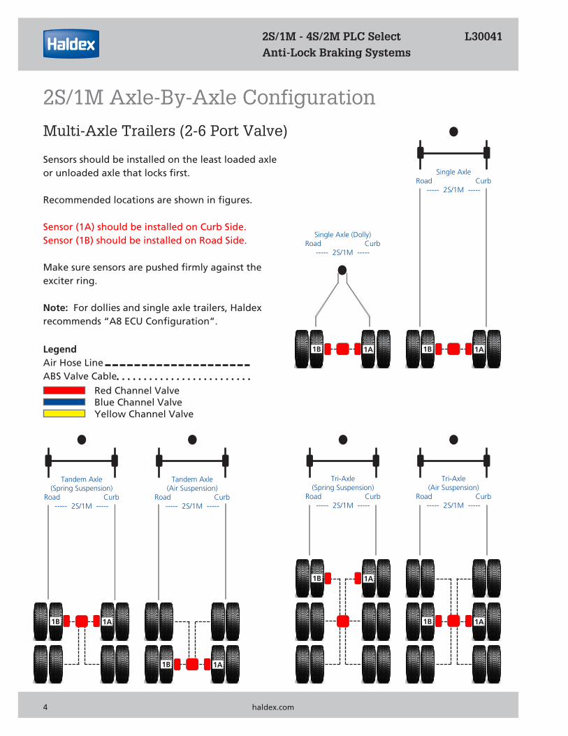
Red Channel ValveBlue Channel ValveYellow Channel Valve
Tandem Axle(Spring Suspension)
Road Curb----- 2S/1M -----
Multi-Axle Trailers (2-6 Port Valve)
Sensors should be installed on the least loaded axleor unloaded axle that locks first.
Recommended locations are shown in figures.
Sensor (1A) should be installed on Curb Side.Sensor (1B) should be installed on Road Side.
Make sure sensors are pushed firmly against the exciter ring.
Note: For dollies and single axle trailers, Haldexrecommends “A8 ECU Configuration”.
1A1B
Tandem Axle(Air Suspension)
Road Curb----- 2S/1M -----
1A1B
Tri-Axle(Spring Suspension)
Road Curb----- 2S/1M -----
1A1B
Tri-Axle(Air Suspension)
Road Curb----- 2S/1M -----
1A1B
Single AxleRoad Curb
----- 2S/1M -----
1A1B1A1B
Single Axle (Dolly)Road Curb
----- 2S/1M -----
LegendAir Hose LineABS Valve Cable
4 haldex.com
2S/1M - 4S/2M PLC Select L30041 Anti-Lock Braking Systems
2S/1M Axle-By-Axle Configuration
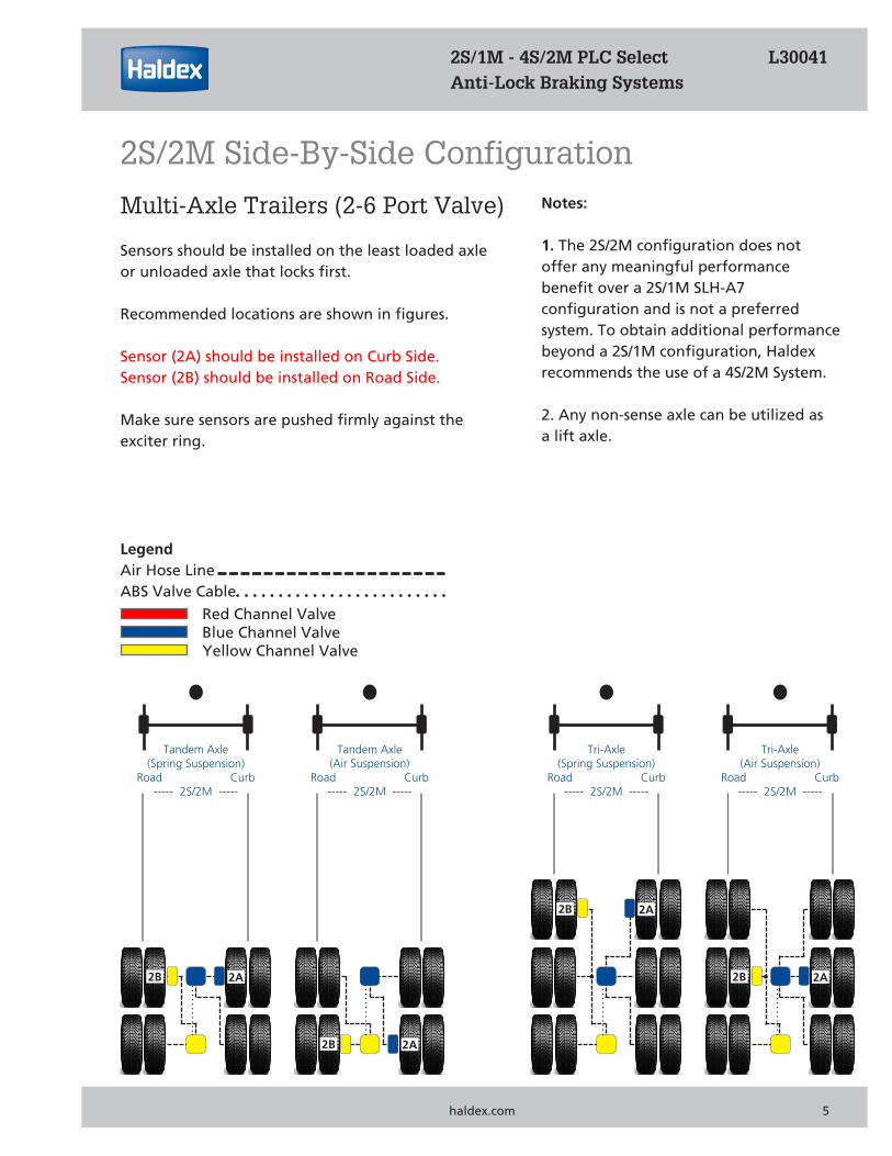
Multi-Axle Trailers (2-6 Port Valve)
Sensors should be installed on the least loaded axle or unloaded axle that locks first.
Recommended locations are shown in figures.
Sensor (2A) should be installed on Curb Side.Sensor (2B) should be installed on Road Side.
Make sure sensors are pushed firmly against the exciter ring.
Notes:
1. The 2S/2M configuration does not offer any meaningful performance benefit over a 2S/1M SLH-A7 configuration and is not a preferred system. To obtain additional performance beyond a 2S/1M configuration, Haldex recommends the use of a 4S/2M System.
2. Any non-sense axle can be utilized as a lift axle.
Tandem Axle(Spring Suspension)
Road Curb----- 2S/2M -----
2A2B
Tandem Axle(Air Suspension)
Road Curb----- 2S/2M -----
2A2B
Tri-Axle(Spring Suspension)
Road Curb----- 2S/2M -----
Tri-Axle(Air Suspension)
Road Curb----- 2S/2M -----
2A2B
2A2B
PLC Select 1M & Page 1
2S/1M - 4S/2M PLC Select L30041 Anti-Lock Braking Systems
haldex.com 5
2S/2M Side-By-Side Configuration
Red Channel ValveBlue Channel ValveYellow Channel Valve
LegendAir Hose LineABS Valve Cable
Tandem Axle(Spring Suspension)
Road Curb----- 4S/2M -----
3A3B
Tandem Axle(Air Suspension)
Road Curb----- 4S/2M -----
2A2B
Tri-Axle(Spring Suspension)
Road Curb----- 4S/2M -----
2A2B
Tri-Axle(Air Suspension)
Road Curb----- 4S/2M -----
2A2B
3A3B
3A3B
2A2B
3A3B
6 haldex.com
2S/1M - 4S/2M PLC Select L30041 Anti-Lock Braking Systems
Red Channel ValveBlue Channel ValveYellow Channel Valve
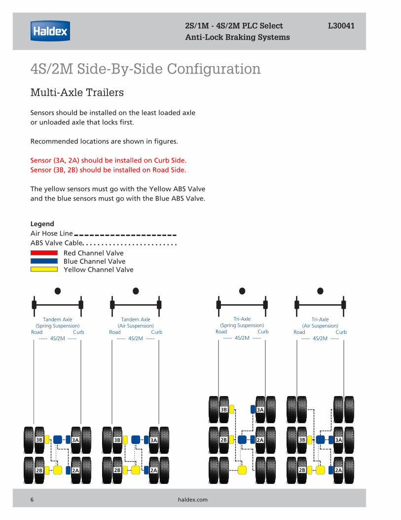
Multi-Axle Trailers
Sensors should be installed on the least loaded axleor unloaded axle that locks first.
Recommended locations are shown in figures.
Sensor (3A, 2A) should be installed on Curb Side.Sensor (3B, 2B) should be installed on Road Side.
The yellow sensors must go with the Yellow ABS Valve and the blue sensors must go with the Blue ABS Valve.
LegendAir Hose LineABS Valve Cable
4S/2M Side-By-Side Configuration
Quad-Axle(Air Suspension)
Road Curb----- 4S/2M -----
2A2B
3A3B
Tri-Axle(Spring Suspension)
Road Curb----- 4S/2M -----
Tandem Axle(Spring Suspension)
Road Curb----- 4S/2M -----
3A3B
Tandem Axle(Air Suspension)
Road Curb----- 4S/2M -----
2A2B2A2B
3A3B
--Lift Axle-- --Lift Axle-- --Lift Axle--
--Lift Axle--
--Lift Axle----Lift Axle--
--Lift Axle--
2A2B
3A3B
PLC Select 1M & Page 1
2S/1M - 4S/2M PLC Select L30041 Anti-Lock Braking Systems
haldex.com 7
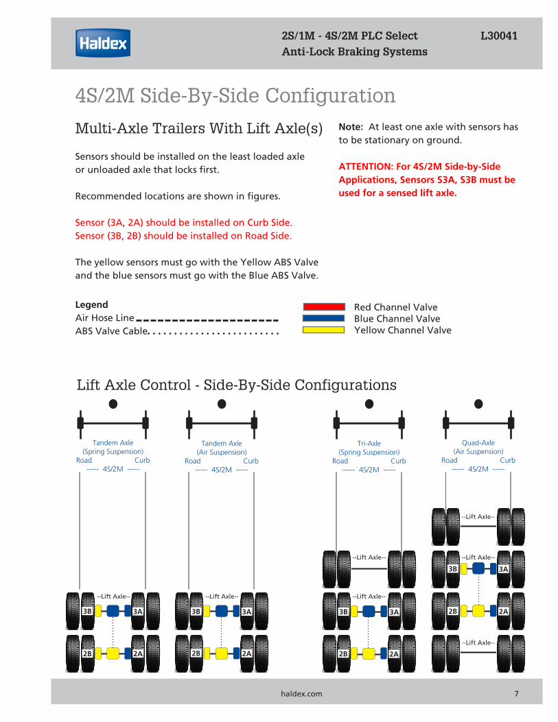
Multi-Axle Trailers With Lift Axle(s)
Sensors should be installed on the least loaded axle or unloaded axle that locks first.
Recommended locations are shown in figures.
Sensor (3A, 2A) should be installed on Curb Side.Sensor (3B, 2B) should be installed on Road Side.
The yellow sensors must go with the Yellow ABS Valve and the blue sensors must go with the Blue ABS Valve.
Note: At least one axle with sensors has to be stationary on ground.
ATTENTION: For 4S/2M Side-by-Side Applications, Sensors S3A, S3B must be used for a sensed lift axle.
4S/2M Side-By-Side Configuration
Red Channel ValveBlue Channel ValveYellow Channel Valve
LegendAir Hose LineABS Valve Cable
Lift Axle Control - Side-By-Side Configurations

Tandem Axle(Spring Suspension)
Road Curb----- 4S/2M -----
2A3A
Tandem Axle(Air Suspension)
Road Curb----- 4S/2M -----
2B3B
Tri-Axle(Spring Suspension)
Road Curb----- 4S/2M -----
2B3B
Tri-Axle(Air Suspension)
Road Curb----- 4S/2M -----
2B3B
2A3A
2A3A
2B3B
2A3A
8 haldex.com
2S/1M - 4S/2M PLC Select L30041 Anti-Lock Braking Systems
Red Channel ValveBlue Channel ValveYellow Channel Valve
Multi-Axle Trailers
Sensors should be installed on the least loaded axleor unloaded axle that locks first.
Recommended locations are shown in figures.
Sensor (2A, 2B) should be installed on Curb Side.Sensor (3A, 3B) should be installed on Road Side.
The yellow sensors must go with the Yellow ABS Valve and the blue sensors must go with the Blue ABS Valve.
LegendAir Hose LineABS Valve Cable
4S/2M Axle-By-Axle Configuration
Quad-Axle(Spring Suspension)
Road Curb----- 4S/2M -----
2B3B
2A3A
Tri-Axle(Spring Suspension)
Road Curb----- 4S/2M -----
Tandem Axle(Spring Suspension)
Road Curb----- 4S/2M -----
2A3A
Tandem Axle(Air Suspension)
Road Curb----- 4S/2M --------
2B3B2B3B
2A3A
2B3B
2A3A
PLC Select 1M &
2S/1M - 4S/2M PLC Select L30041 Anti-Lock Braking Systems
haldex.com 9
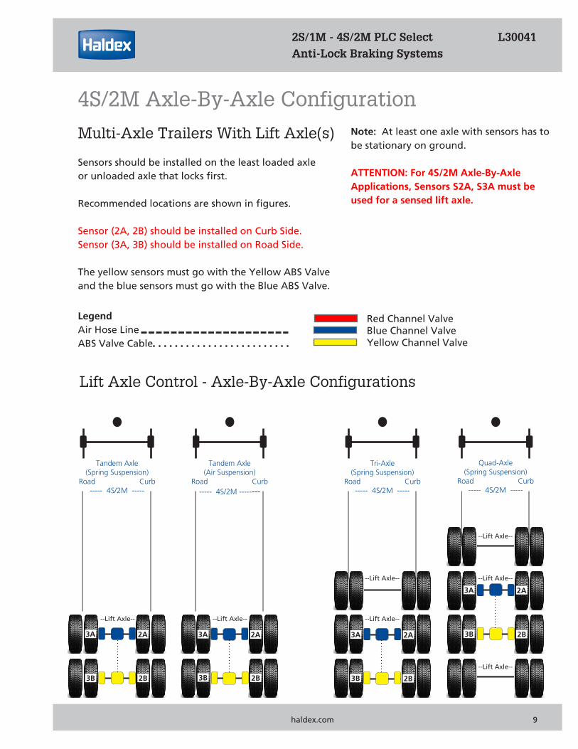
Multi-Axle Trailers With Lift Axle(s)
Sensors should be installed on the least loaded axle or unloaded axle that locks first.
Recommended locations are shown in figures.
Sensor (2A, 2B) should be installed on Curb Side.Sensor (3A, 3B) should be installed on Road Side.
The yellow sensors must go with the Yellow ABS Valve and the blue sensors must go with the Blue ABS Valve.
Note: At least one axle with sensors has to be stationary on ground.
ATTENTION: For 4S/2M Axle-By-AxleApplications, Sensors S2A, S3A must be used for a sensed lift axle.
4S/2M Axle-By-Axle Configuration
Red Channel ValveBlue Channel ValveYellow Channel Valve
LegendAir Hose LineABS Valve Cable
Lift Axle Control - Axle-By-Axle Configurations
--Lift Axle--
--Lift Axle--
--Lift Axle----Lift Axle--
--Lift Axle--
--Lift Axle-- --Lift Axle--
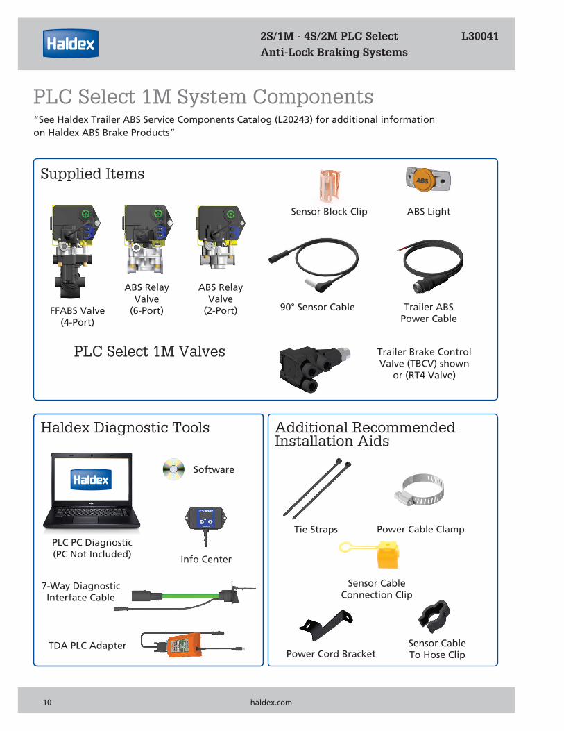
FFABS Valve(4-Port)
ABS Relay Valve
(2-Port)
ABS Relay Valve
(6-Port)
PLC Select 1M Valves
Supplied Items
Trailer Brake Control Valve (TBCV) shown
or (RT4 Valve)
Haldex Diagnostic Tools Additional Recommended Installation Aids
Sensor Block Clip ABS Light
90° Sensor Cable Trailer ABSPower Cable
“See Haldex Trailer ABS Service Components Catalog (L20243) for additional information on Haldex ABS Brake Products”
Tie Straps Power Cable Clamp
Power Cord Bracket
Info Center
TDA PLC Adapter
PLC PC Diagnostic(PC Not Included)
Software
7-Way DiagnosticInterface Cable
2S/1M - 4S/2M PLC Select L30041 Anti-Lock Braking Systems
10 haldex.com
PLC Select 1M System Components
Sensor CableTo Hose Clip
Sensor CableConnection Clip
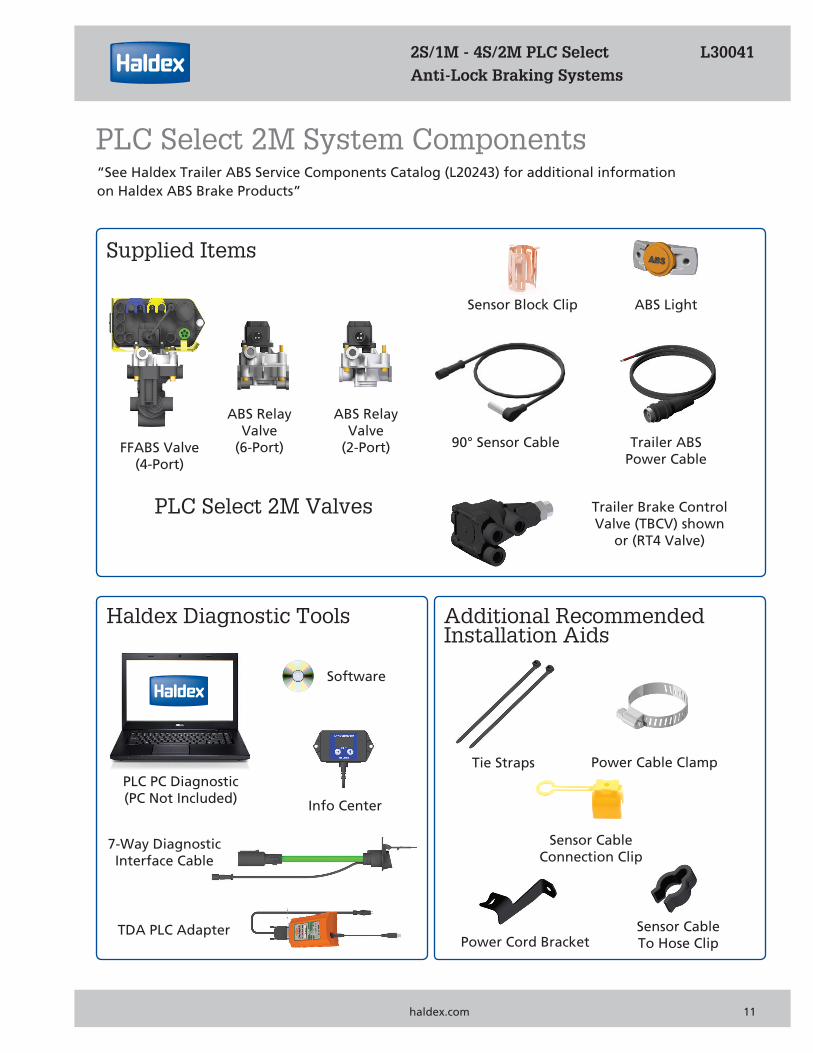
“See Haldex Trailer ABS Service Components Catalog (L20243) for additional information on Haldex ABS Brake Products”
2S/1M - 4S/2M PLC Select L30041 Anti-Lock Braking Systems
PLC Select 1M & haldex.com 11
PLC Select 2M System Components
Sensor CableTo Hose Clip
FFABS Valve(4-Port)
ABS Relay Valve
(2-Port)
ABS Relay Valve
(6-Port)
PLC Select 2M Valves
Supplied Items
Trailer Brake Control Valve (TBCV) shown
or (RT4 Valve)
Haldex Diagnostic Tools Additional Recommended Installation Aids
Sensor Block Clip ABS Light
90° Sensor Cable Trailer ABSPower Cable
Tie Straps Power Cable Clamp
Power Cord Bracket
Info Center
TDA PLC Adapter
PLC PC Diagnostic(PC Not Included)
Software
7-Way DiagnosticInterface Cable
Sensor CableConnection Clip
Front View Right Side ViewLeft Side View
2
1
6
5
3
4
Notes:
1. FFABS Valve is commonly used for Tandem Axle Trailers.2. For Single Axle Trailers use (2) Service Brake Port.3. All ports are 3/8” NPT Service and Delivery.4. Reservoir port 1/2” and 3/4” NPT.5. Service/Control and Emergency/Supply have a
serviceable “Filter Screen” (7 & 8) installed.6. Attach hoses to appropriate brake chambers.
Use liquid thread sealant sparingly on all fittings.(Loctite PST565 or Equivalent)
7. Do Not bottom out fittings it will damage FFABS Valve.See Installation Steps 1-4 on Page 17.
6
8
7
4
9
White Exhaust Coverindicates
“Spring Brake Priority”
Black Exhaust Coverindicates
“Service Brake Priority”
2 2
2S/1M - 4S/2M PLC Select L30041Anti-Lock Braking Systems
12 haldex.com
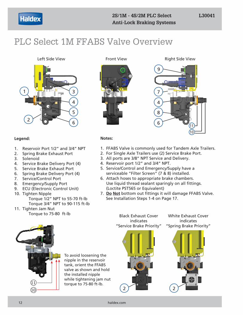
PLC Select 1M FFABS Valve Overview
11
10
1110
Legend:
1. Reservoir Port 1/2” and 3/4” NPT2. Spring Brake Exhaust Port3. Solenoid4. Service Brake Delivery Port (4)5. Service Brake Exhaust Port6. Spring Brake Delivery Port (4)7. Service/Control Port8. Emergency/Supply Port9. ECU (Electronic Control Unit)10. Tighten Nipple
Torque 1/2” NPT to 55-70 ft-lbTorque 3/4” NPT to 90-115 ft-lb
11. Tighten Jam NutTorque to 75-80 ft-lb
To avoid loosening the nipple in the reservoir tank, orient the FFABS valve as shown and hold the installed nipple while tightening jam nut torque to 75-80 ft-lb.
Front View Right Side ViewLeft Side View
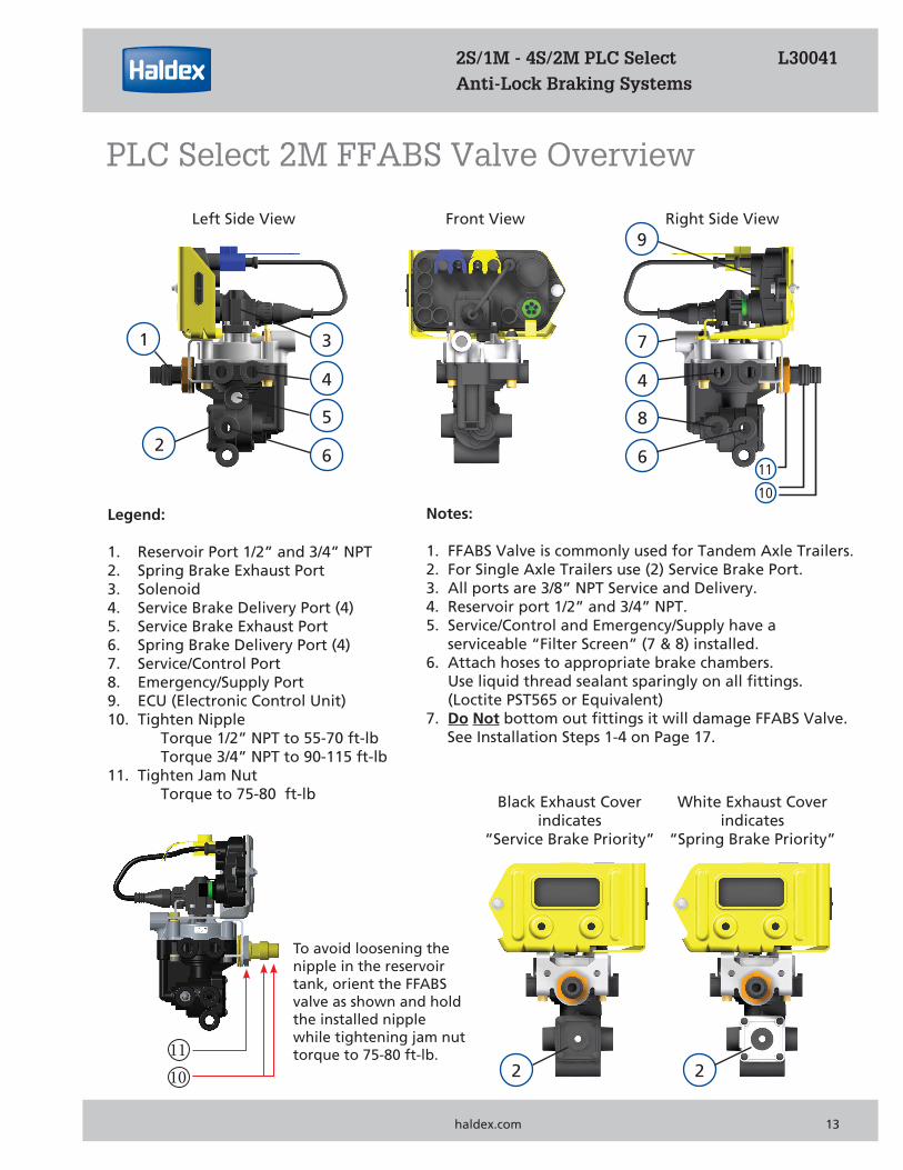
Notes:
1. FFABS Valve is commonly used for Tandem Axle Trailers.2. For Single Axle Trailers use (2) Service Brake Port.3. All ports are 3/8” NPT Service and Delivery.4. Reservoir port 1/2” and 3/4” NPT.5. Service/Control and Emergency/Supply have a
serviceable “Filter Screen” (7 & 8) installed.6. Attach hoses to appropriate brake chambers.
Use liquid thread sealant sparingly on all fittings.(Loctite PST565 or Equivalent)
7. Do Not bottom out fittings it will damage FFABS Valve.See Installation Steps 1-4 on Page 17.
White Exhaust Coverindicates
“Spring Brake Priority”
Black Exhaust Coverindicates
“Service Brake Priority”
2
1
6
5
3
4
6
8
7
4
9
2 2
2S/1M - 4S/2M PLC Select L30041Anti-Lock Braking Systems
PLC Select 1M & haldex.com 13
PLC Select 2M FFABS Valve Overview
11
10
1110
Legend:
1. Reservoir Port 1/2” and 3/4” NPT2. Spring Brake Exhaust Port3. Solenoid4. Service Brake Delivery Port (4)5. Service Brake Exhaust Port6. Spring Brake Delivery Port (4)7. Service/Control Port8. Emergency/Supply Port9. ECU (Electronic Control Unit)10. Tighten Nipple
Torque 1/2” NPT to 55-70 ft-lbTorque 3/4” NPT to 90-115 ft-lb
11. Tighten Jam NutTorque to 75-80 ft-lb
To avoid loosening the nipple in the reservoir tank, orient the FFABS valve as shown and hold the installed nipple while tightening jam nut torque to 75-80 ft-lb.
21
5
34
6
2
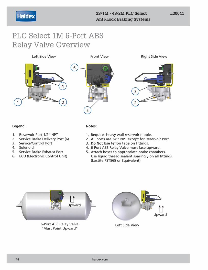
6-Port ABS Relay Valve“Must Point Upward”
Upward
Upward
Left Side View
2S/1M - 4S/2M PLC Select L30041Anti-Lock Braking Systems
PLC Select 1M 6-Port ABS Relay Valve Overview
Legend:
1. Reservoir Port 1/2” NPT2. Service Brake Delivery Port (6)3. Service/Control Port4. Solenoid5. Service Brake Exhaust Port6. ECU (Electronic Control Unit)
Notes:
1. Requires heavy wall reservoir nipple.2. All ports are 3/8” NPT except for Reservoir Port.3. Do Not Use teflon tape on fittings.4. 6-Port ABS Relay Valve must face upward.5. Attach hoses to appropriate brake chambers.
Use liquid thread sealant sparingly on all fittings.(Loctite PST565 or Equivalent)
14 haldex.com
Front View Right Side ViewLeft Side View
21
5
34
6
2
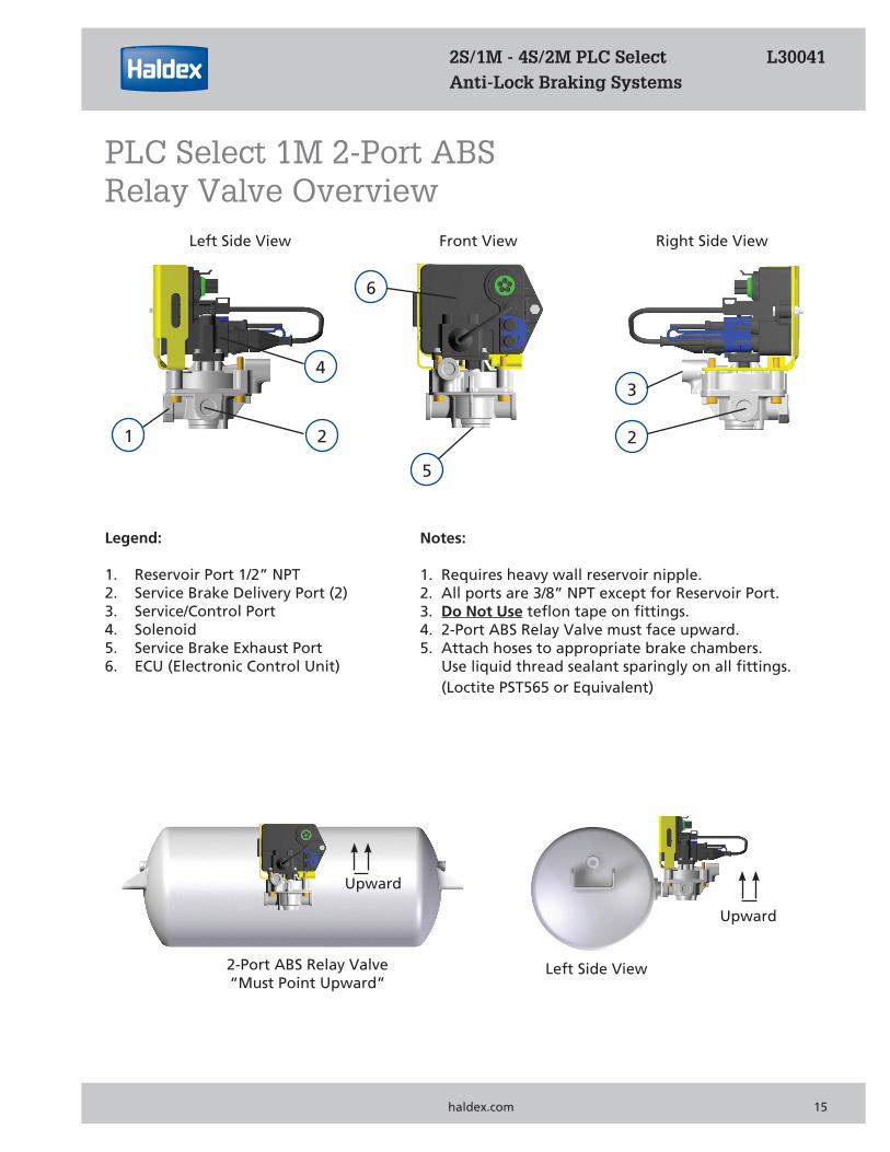
2-Port ABS Relay Valve“Must Point Upward”
Upward
Upward
Left Side View
2S/1M - 4S/2M PLC Select L30041Anti-Lock Braking Systems
PLC Select 1M 2-Port ABS Relay Valve Overview
Legend:
1. Reservoir Port 1/2” NPT2. Service Brake Delivery Port (2)3. Service/Control Port4. Solenoid5. Service Brake Exhaust Port6. ECU (Electronic Control Unit)
Notes:
1. Requires heavy wall reservoir nipple.2. All ports are 3/8” NPT except for Reservoir Port.3. Do Not Use teflon tape on fittings.4. 2-Port ABS Relay Valve must face upward.5. Attach hoses to appropriate brake chambers.
Use liquid thread sealant sparingly on all fittings.(Loctite PST565 or Equivalent)
PLC Select 1M & haldex.com 15
Front View Right Side ViewLeft Side View
2
1
53
2
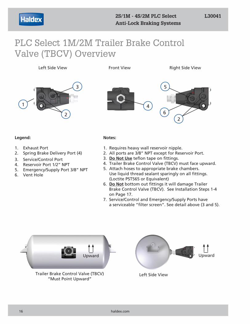
Trailer Brake Control Valve (TBCV)“Must Point Upward”
Upward Upward
Left Side View
46
2S/1M - 4S/2M PLC Select L30041Anti-Lock Braking Systems
PLC Select 1M/2M Trailer Brake Control Valve (TBCV) Overview
Legend:
1. Exhaust Port2. Spring Brake Delivery Port (4)
3. Service/Control Port4. Reservoir Port 1/2” NPT5. Emergency/Supply Port 3/8” NPT6. Vent Hole
Notes:
1. Requires heavy wall reservoir nipple.2. All ports are 3/8” NPT except for Reservoir Port.3. Do Not Use teflon tape on fittings.4. Trailer Brake Control Valve (TBCV) must face upward.5. Attach hoses to appropriate brake chambers.
Use liquid thread sealant sparingly on all fittings.(Loctite PST565 or Equivalent)
6. Do Not bottom out fittings it will damage TrailerBrake Control Valve (TBCV). See Installation Steps 1-4on Page 17.
7. Service/Control and Emergency/Supply Ports havea serviceable “filter screen”. See detail above (3 and 5).
16 haldex.com
Front View Right Side ViewLeft Side View
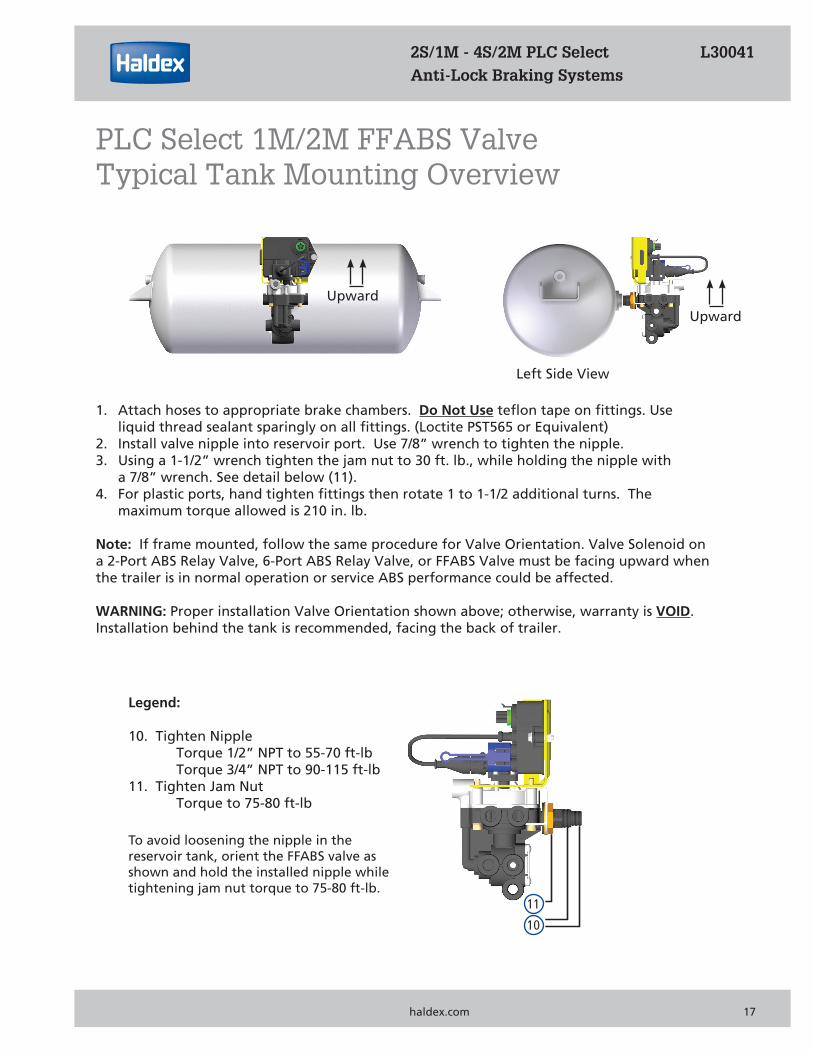
1. Attach hoses to appropriate brake chambers. Do Not Use teflon tape on fittings. Useliquid thread sealant sparingly on all fittings. (Loctite PST565 or Equivalent)
2. Install valve nipple into reservoir port. Use 7/8” wrench to tighten the nipple.3. Using a 1-1/2” wrench tighten the jam nut to 30 ft. lb., while holding the nipple with
a 7/8” wrench. See detail below (11).4. For plastic ports, hand tighten fittings then rotate 1 to 1-1/2 additional turns. The
maximum torque allowed is 210 in. lb.
Note: If frame mounted, follow the same procedure for Valve Orientation. Valve Solenoid on a 2-Port ABS Relay Valve, 6-Port ABS Relay Valve, or FFABS Valve must be facing upward when the trailer is in normal operation or service ABS performance could be affected.
WARNING: Proper installation Valve Orientation shown above; otherwise, warranty is VOID. Installation behind the tank is recommended, facing the back of trailer.
Upward
Left Side View
Upward
Legend:
10. Tighten NippleTorque 1/2” NPT to 55-70 ft-lbTorque 3/4” NPT to 90-115 ft-lb
11. Tighten Jam NutTorque to 75-80 ft-lb
2S/1M - 4S/2M PLC Select L30041Anti-Lock Braking Systems
PLC Select 1M/2M FFABS Valve Typical Tank Mounting Overview
PLC Select 1M & haldex.com 17
11
10
To avoid loosening the nipple in the reservoir tank, orient the FFABS valve as shown and hold the installed nipple while tightening jam nut torque to 75-80 ft-lb.
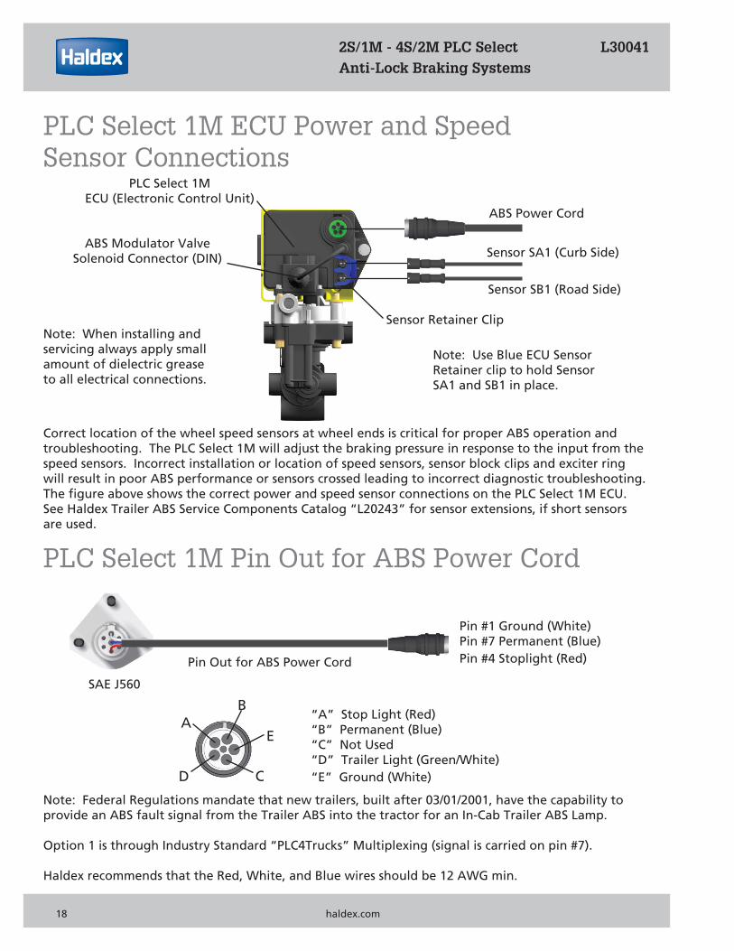
PLC Select 1MECU (Electronic Control Unit)
ABS Power Cord
ABS Modulator ValveSolenoid Connector (DIN) Sensor SA1 (Curb Side)
Sensor SB1 (Road Side)
Correct location of the wheel speed sensors at wheel ends is critical for proper ABS operation and troubleshooting. The PLC Select 1M will adjust the braking pressure in response to the input from the speed sensors. Incorrect installation or location of speed sensors, sensor block clips and exciter ring will result in poor ABS performance or sensors crossed leading to incorrect diagnostic troubleshooting.The figure above shows the correct power and speed sensor connections on the PLC Select 1M ECU.See Haldex Trailer ABS Service Components Catalog “L20243” for sensor extensions, if short sensors are used.
Note: Federal Regulations mandate that new trailers, built after 03/01/2001, have the capability to provide an ABS fault signal from the Trailer ABS into the tractor for an In-Cab Trailer ABS Lamp. Option 1 is through Industry Standard “PLC4Trucks” Multiplexing (signal is carried on pin #7).
Haldex recommends that the Red, White, and Blue wires should be 12 AWG min.
Pin #1 Ground (White)Pin #7 Permanent (Blue)Pin #4 Stoplight (Red)
SAE J560
Pin Out for ABS Power Cord
Note: When installing and servicing always apply small amount of dielectric grease to all electrical connections.
Note: Use Blue ECU Sensor Retainer clip to hold Sensor SA1 and SB1 in place.
Sensor Retainer Clip
BA
D C
E
“A” Stop Light (Red)“B” Permanent (Blue)“C” Not Used “D” Trailer Light (Green/White)“E” Ground (White)
18 haldex.com
2S/1M - 4S/2M PLC Select L30041 Anti-Lock Braking Systems
PLC Select 1M ECU Power and SpeedSensor Connections
PLC Select 1M Pin Out for ABS Power Cord
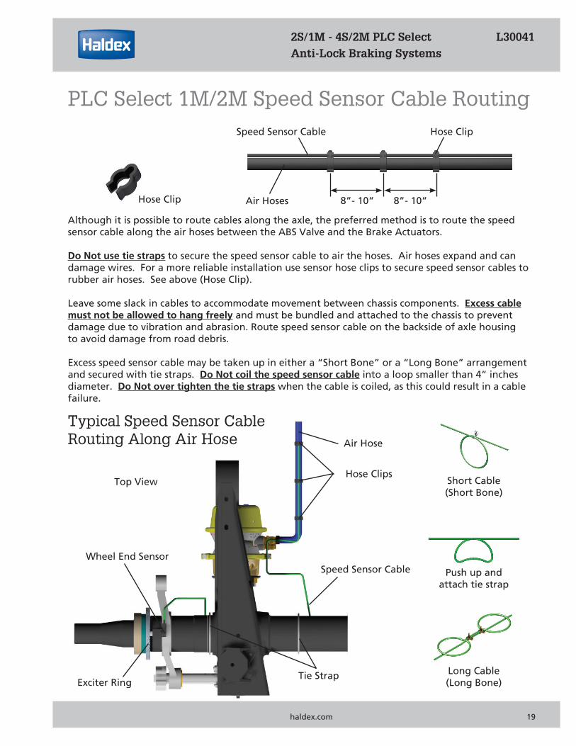
Although it is possible to route cables along the axle, the preferred method is to route the speed sensor cable along the air hoses between the ABS Valve and the Brake Actuators.
Do Not use tie straps to secure the speed sensor cable to air the hoses. Air hoses expand and can damage wires. For a more reliable installation use sensor hose clips to secure speed sensor cables to rubber air hoses. See above (Hose Clip).
Leave some slack in cables to accommodate movement between chassis components. Excess cablemust not be allowed to hang freely and must be bundled and attached to the chassis to prevent damage due to vibration and abrasion. Route speed sensor cable on the backside of axle housing to avoid damage from road debris.
Excess speed sensor cable may be taken up in either a “Short Bone” or a “Long Bone” arrangement and secured with tie straps. Do Not coil the speed sensor cable into a loop smaller than 4” inches diameter. Do Not over tighten the tie straps when the cable is coiled, as this could result in a cable failure.
Hose Clip Air Hoses
Hose ClipSpeed Sensor Cable
8”- 10” 8”- 10”
Push up and attach tie strap
Short Cable(Short Bone)
Long Cable(Long Bone)
Typical Speed Sensor Cable Routing Along Air Hose Air Hose
Hose Clips
Speed Sensor CableWheel End Sensor
Tie StrapExciter Ring
Top View
PLC Select 1M & haldex.com 19
2S/1M - 4S/2M PLC Select L30041 Anti-Lock Braking Systems
PLC Select 1M/2M Speed Sensor Cable Routing
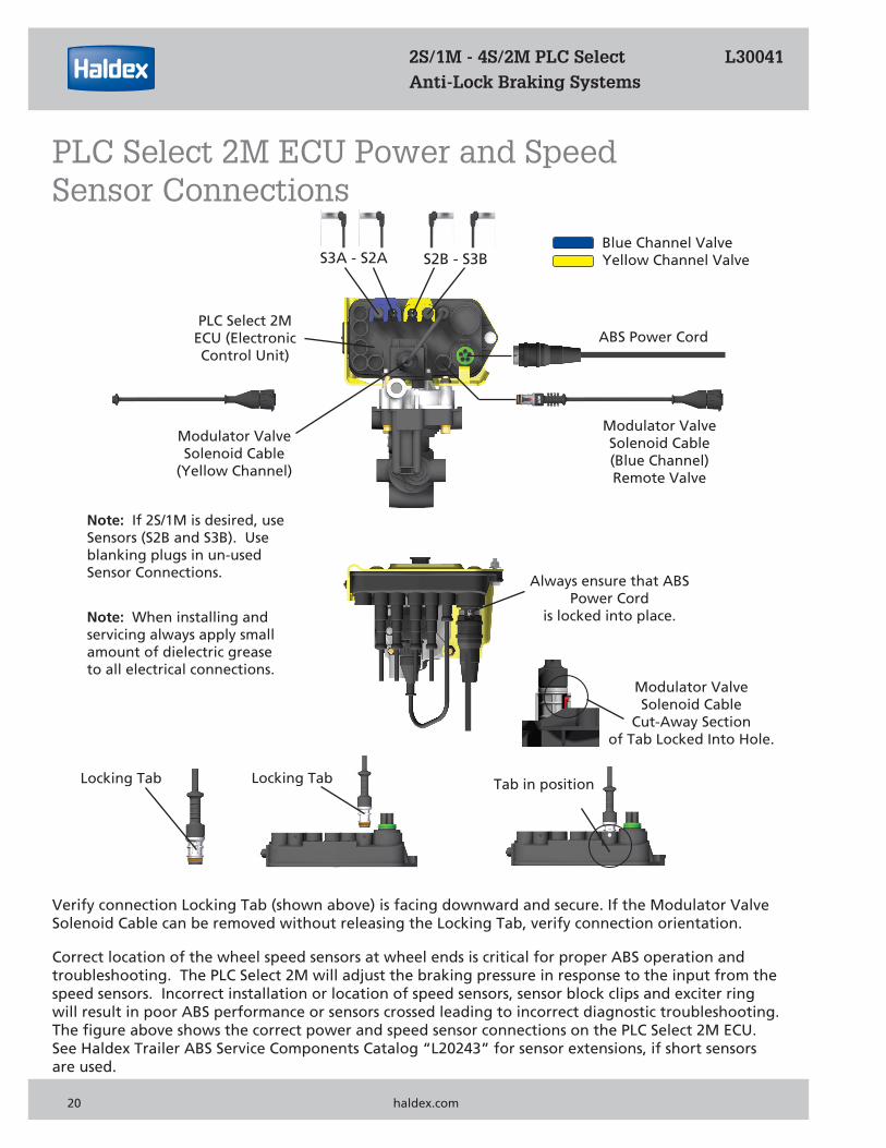
S3A - S2A S2B - S3B
Modulator Valve Solenoid Cable(Blue Channel) Remote Valve
ABS Power CordPLC Select 2M
ECU (Electronic Control Unit)
Modulator Valve Solenoid Cable
(Yellow Channel)
Note: If 2S/1M is desired, use Sensors (S2B and S3B). Use blanking plugs in un-used Sensor Connections. Always ensure that ABS
Power Cordis locked into place.
Correct location of the wheel speed sensors at wheel ends is critical for proper ABS operation and troubleshooting. The PLC Select 2M will adjust the braking pressure in response to the input from the speed sensors. Incorrect installation or location of speed sensors, sensor block clips and exciter ring will result in poor ABS performance or sensors crossed leading to incorrect diagnostic troubleshooting.The figure above shows the correct power and speed sensor connections on the PLC Select 2M ECU. See Haldex Trailer ABS Service Components Catalog “L20243” for sensor extensions, if short sensors are used.
Verify connection Locking Tab (shown above) is facing downward and secure. If the Modulator Valve Solenoid Cable can be removed without releasing the Locking Tab, verify connection orientation.
Locking Tab Tab in position
Note: When installing and servicing always apply small amount of dielectric grease to all electrical connections.
Modulator ValveSolenoid Cable
Cut-Away Sectionof Tab Locked Into Hole.
Blue Channel ValveYellow Channel Valve
Locking Tab
2S/1M - 4S/2M PLC Select L30041 Anti-Lock Braking Systems
PLC Select 2M ECU Power and SpeedSensor Connections
20 haldex.com
2S/1M - 4S/2M PLC Select L30041 Anti-Lock Braking Systems
NOTES
PLC Select 1M & haldex.com 21
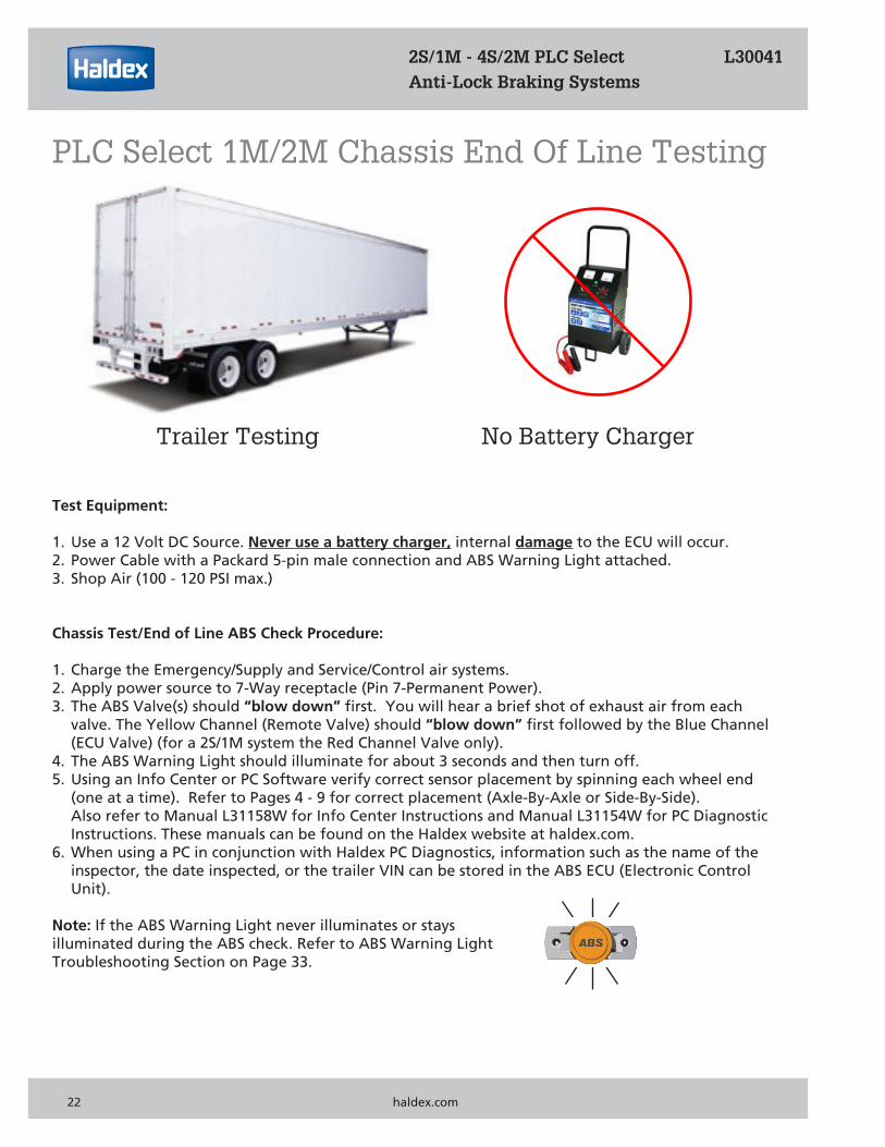
Trailer Testing No Battery Charger
Test Equipment:
1. Use a 12 Volt DC Source. Never use a battery charger, internal damage to the ECU will occur.2. Power Cable with a Packard 5-pin male connection and ABS Warning Light attached.3. Shop Air (100 - 120 PSI max.)
Chassis Test/End of Line ABS Check Procedure:
1. Charge the Emergency/Supply and Service/Control air systems.2. Apply power source to 7-Way receptacle (Pin 7-Permanent Power).3. The ABS Valve(s) should “blow down” first. You will hear a brief shot of exhaust air from each valve. The Yellow Channel (Remote Valve) should “blow down” first followed by the Blue Channel (ECU Valve) (for a 2S/1M system the Red Channel Valve only).4. The ABS Warning Light should illuminate for about 3 seconds and then turn off.5. Using an Info Center or PC Software verify correct sensor placement by spinning each wheel end (one at a time). Refer to Pages 4 - 9 for correct placement (Axle-By-Axle or Side-By-Side). Also refer to Manual L31158W for Info Center Instructions and Manual L31154W for PC Diagnostic Instructions. These manuals can be found on the Haldex website at haldex.com. 6. When using a PC in conjunction with Haldex PC Diagnostics, information such as the name of the inspector, the date inspected, or the trailer VIN can be stored in the ABS ECU (Electronic Control Unit).
Note: If the ABS Warning Light never illuminates or stays illuminated during the ABS check. Refer to ABS Warning LightTroubleshooting Section on Page 33.
2S/1M - 4S/2M PLC Select L30041 Anti-Lock Braking Systems
PLC Select 1M/2M Chassis End Of Line Testing
22 haldex.com
Road Testing Procedure:
1. Connect a tractor to the trailer and charge the trailer’s air tanks (100 - 120 psi).2. Turn on the start switch and ensure that the ABS Warning Light comes on about 3 seconds, then goes out.3. Pull the trailer at a speed greater than 6 mph, make a brake application and hold until the trailer has come to a complete stop.4. Verify that the ABS Warning Light has remained “OFF”. If the ABS Warning Light remained “OFF”, the system is functioning properly.5. If the ABS System detected an error during the brake application, the ABS Warning Light will be “ON”. If the ABS Warning Light never comes “ON” when the start switch is turned “ON”, or if the ABS Warning Light stays “ON” with the start switch “ON”. Refer to ABS Warning Light Troubleshooting Section on Page 33.
Notes:
1. Disconnect power from the ABS System before making any repairs.2. Most ABS problems are related to the following items: a. Cut or Damaged Wires b. Corroded Connector or Terminals c. Connector Terminals not Latched or Seated correctly to Mating Assemblies d. Excessive Sensor Air Gap, Sensor Clip Retention or Wheel Bearing End Play e. Insufficient power at the ABS Power Cable (12 - 15 Volts DC)3. After making any repairs go to the Diagnostic Tools Section on Pages 24 - 26 to confirm that the fault has been corrected. If Dynamic Fault Codes 11 - 16 or 21 - 26 have occurred the ABS Warning Light will remain “ON” with a code “07” when repowered until the problem has been corrected. After correcting the Stored Fault(s), each affected wheel must spin >1 mph utilizing permanent power for the ABS System to recognize the problem has been corrected. Verify the ABS Warning Light turns “OFF” before clearing Stored Dynamic Fault Codes.
2S/1M - 4S/2M PLC Select L30041 Anti-Lock Braking Systems
PLC Select 1M/2M Road Testing
PLC Select 1M & haldex.com 23
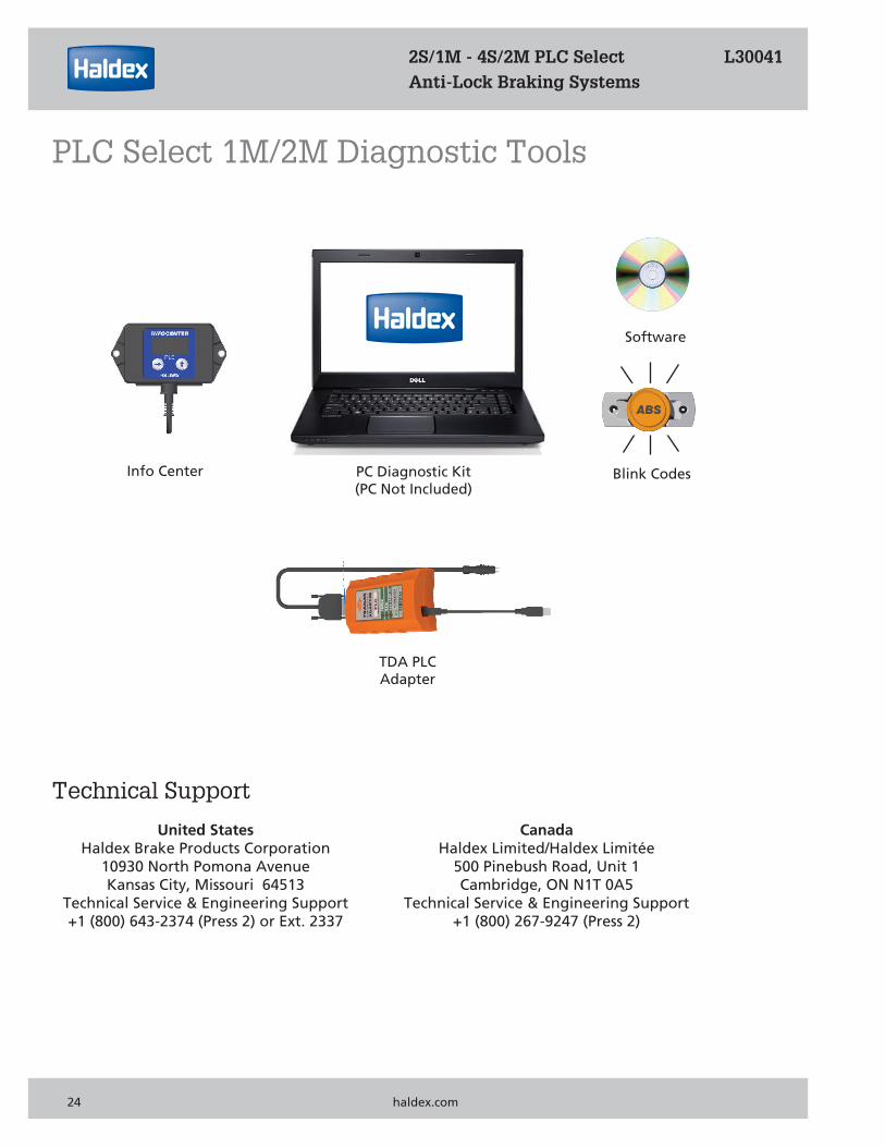
Technical Support
United States Canada Haldex Brake Products Corporation Haldex Limited/Haldex Limitée 10930 North Pomona Avenue 500 Pinebush Road, Unit 1 Kansas City, Missouri 64513 Cambridge, ON N1T 0A5 Technical Service & Engineering Support Technical Service & Engineering Support +1 (800) 643-2374 (Press 2) or Ext. 2337 +1 (800) 267-9247 (Press 2)
Info Center PC Diagnostic Kit(PC Not Included)
Software
TDA PLCAdapter
Blink Codes
2S/1M - 4S/2M PLC Select L30041 Anti-Lock Braking Systems
PLC Select 1M/2M Diagnostic Tools
24 haldex.com
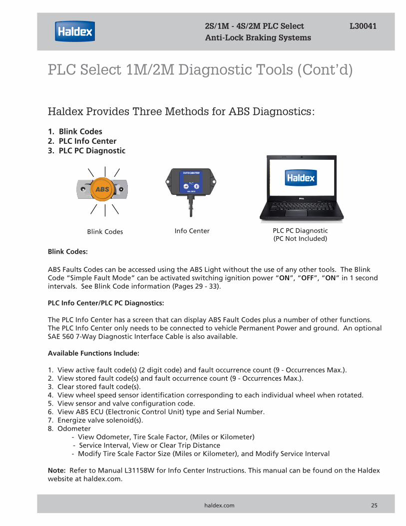
Haldex Provides Three Methods for ABS Diagnostics:
1. Blink Codes2. PLC Info Center3. PLC PC Diagnostic
PLC PC Diagnostic(PC Not Included)
Info CenterBlink Codes
Blink Codes:
ABS Faults Codes can be accessed using the ABS Light without the use of any other tools. The Blink Code “Simple Fault Mode” can be activated switching ignition power “ON”, “OFF”, “ON” in 1 second intervals. See Blink Code information (Pages 29 - 33).
PLC Info Center/PLC PC Diagnostics:
The PLC Info Center has a screen that can display ABS Fault Codes plus a number of other functions. The PLC Info Center only needs to be connected to vehicle Permanent Power and ground. An optionalSAE 560 7-Way Diagnostic Interface Cable is also available.
Available Functions Include:
1. View active fault code(s) (2 digit code) and fault occurrence count (9 - Occurrences Max.).2. View stored fault code(s) and fault occurrence count (9 - Occurrences Max.).3. Clear stored fault code(s).4. View wheel speed sensor identification corresponding to each individual wheel when rotated.5. View sensor and valve configuration code.6. View ABS ECU (Electronic Control Unit) type and Serial Number.7. Energize valve solenoid(s).8. Odometer - View Odometer, Tire Scale Factor, (Miles or Kilometer) - Service Interval, View or Clear Trip Distance - Modify Tire Scale Factor Size (Miles or Kilometer), and Modify Service Interval
Note: Refer to Manual L31158W for Info Center Instructions. This manual can be found on the Haldex website at haldex.com.
2S/1M - 4S/2M PLC Select L30041 Anti-Lock Braking Systems
PLC Select 1M/2M Diagnostic Tools (Cont’d)
PLC Select 1M & haldex.com 25
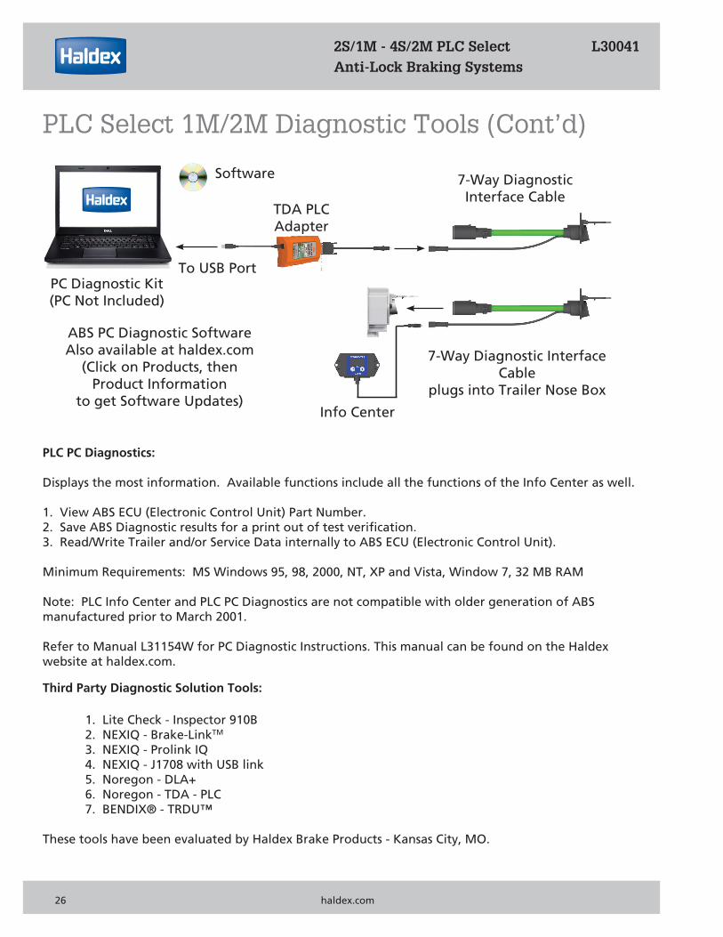
To USB Port
Software 7-Way DiagnosticInterface Cable
TDA PLCAdapter
ABS PC Diagnostic SoftwareAlso available at haldex.com
(Click on Products, then Product Information
to get Software Updates)
PC Diagnostic Kit(PC Not Included)
PLC PC Diagnostics:
Displays the most information. Available functions include all the functions of the Info Center as well.
1. View ABS ECU (Electronic Control Unit) Part Number.2. Save ABS Diagnostic results for a print out of test verification.3. Read/Write Trailer and/or Service Data internally to ABS ECU (Electronic Control Unit).
Minimum Requirements: MS Windows 95, 98, 2000, NT, XP and Vista, Window 7, 32 MB RAM
Note: PLC Info Center and PLC PC Diagnostics are not compatible with older generation of ABSmanufactured prior to March 2001.
Refer to Manual L31154W for PC Diagnostic Instructions. This manual can be found on the Haldex website at haldex.com.
7-Way Diagnostic Interface Cable
plugs into Trailer Nose Box
Third Party Diagnostic Solution Tools:
1. Lite Check - Inspector 910B 2. NEXIQ - Brake-LinkTM
3. NEXIQ - Prolink IQ 4. NEXIQ - J1708 with USB link 5. Noregon - DLA+ 6. Noregon - TDA - PLC 7. BENDIX® - TRDU™
These tools have been evaluated by Haldex Brake Products - Kansas City, MO.
Info Center
2S/1M - 4S/2M PLC Select L30041 Anti-Lock Braking Systems
PLC Select 1M/2M Diagnostic Tools (Cont’d)
26 haldex.com
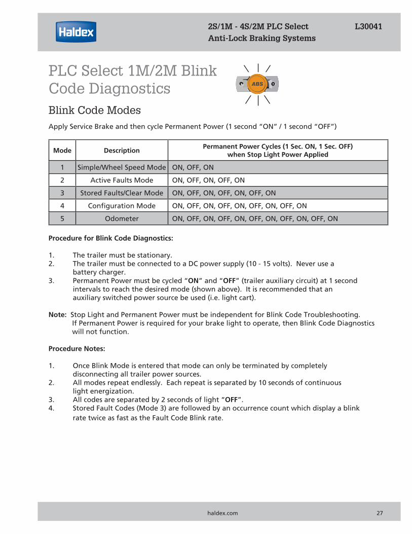
Mode DescriptionPermanent Power Cycles (1 Sec. ON, 1 Sec. OFF)
when Stop Light Power Applied
1 Simple/Wheel Speed Mode ON, OFF, ON
2 Active Faults Mode ON, OFF, ON, OFF, ON
3 Stored Faults/Clear Mode ON, OFF, ON, OFF, ON, OFF, ON
4 Configuration Mode ON, OFF, ON, OFF, ON, OFF, ON, OFF, ON
5 Odometer ON, OFF, ON, OFF, ON, OFF, ON, OFF, ON, OFF, ON
Blink Code ModesApply Service Brake and then cycle Permanent Power (1 second “ON” / 1 second “OFF”)
Procedure for Blink Code Diagnostics:
1. The trailer must be stationary.2. The trailer must be connected to a DC power supply (10 - 15 volts). Never use a battery charger.3. Permanent Power must be cycled “ON” and “OFF” (trailer auxiliary circuit) at 1 second intervals to reach the desired mode (shown above). It is recommended that an auxiliary switched power source be used (i.e. light cart).
Note: Stop Light and Permanent Power must be independent for Blink Code Troubleshooting. If Permanent Power is required for your brake light to operate, then Blink Code Diagnostics will not function.
Procedure Notes:
1. Once Blink Mode is entered that mode can only be terminated by completely disconnecting all trailer power sources.2. All modes repeat endlessly. Each repeat is separated by 10 seconds of continuous light energization.3. All codes are separated by 2 seconds of light “OFF”.4. Stored Fault Codes (Mode 3) are followed by an occurrence count which display a blink rate twice as fast as the Fault Code Blink rate.
2S/1M - 4S/2M PLC Select L30041 Anti-Lock Braking Systems
PLC Select 1M/2M Blink Code Diagnostics
PLC Select 1M & haldex.com 27
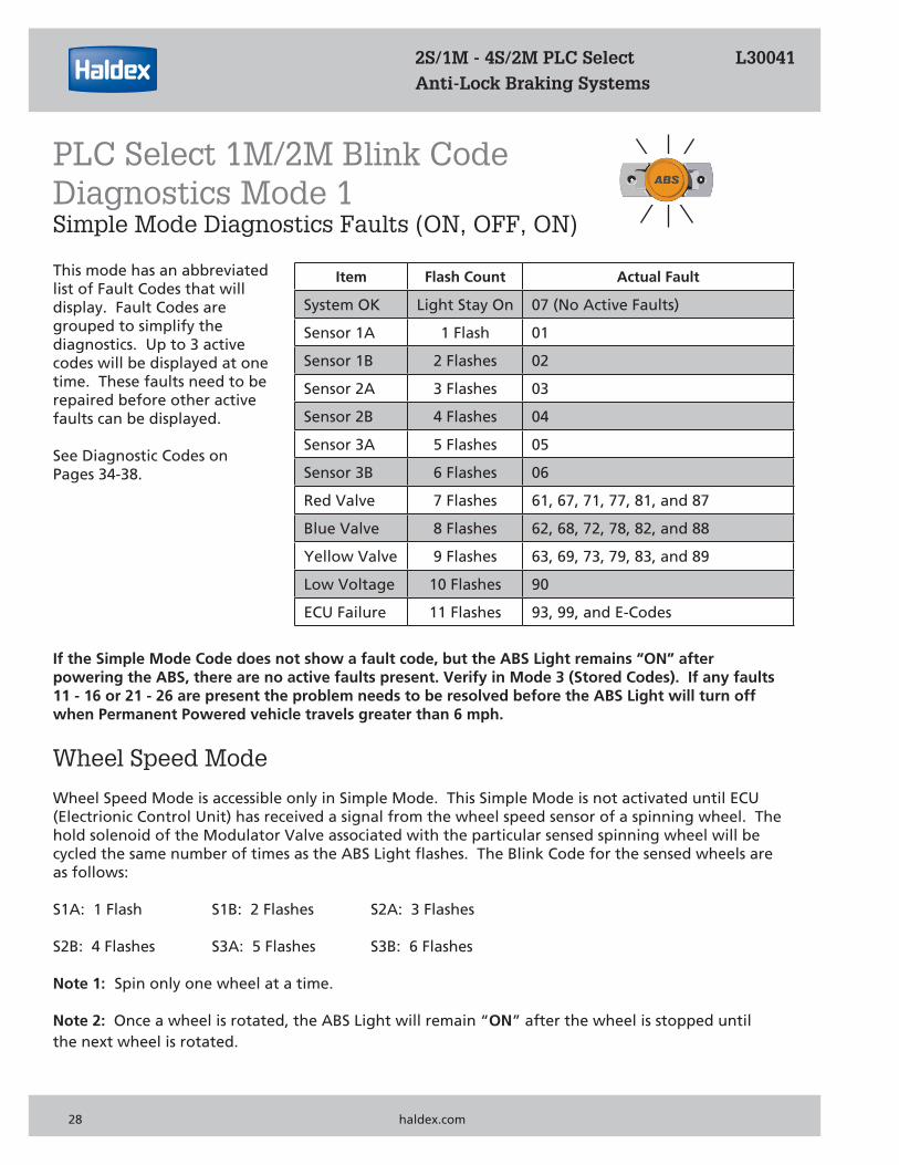
Item Flash Count Actual Fault
System OK Light Stay On 07 (No Active Faults)
Sensor 1A 1 Flash 01
Sensor 1B 2 Flashes 02
Sensor 2A 3 Flashes 03
Sensor 2B 4 Flashes 04
Sensor 3A 5 Flashes 05
Sensor 3B 6 Flashes 06
Red Valve 7 Flashes 61, 67, 71, 77, 81, and 87
Blue Valve 8 Flashes 62, 68, 72, 78, 82, and 88
Yellow Valve 9 Flashes 63, 69, 73, 79, 83, and 89
Low Voltage 10 Flashes 90
ECU Failure 11 Flashes 93, 99, and E-Codes
If the Simple Mode Code does not show a fault code, but the ABS Light remains “ON” after powering the ABS, there are no active faults present. Verify in Mode 3 (Stored Codes). If any faults11 - 16 or 21 - 26 are present the problem needs to be resolved before the ABS Light will turn off when Permanent Powered vehicle travels greater than 6 mph.
Wheel Speed Mode
Wheel Speed Mode is accessible only in Simple Mode. This Simple Mode is not activated until ECU(Electrionic Control Unit) has received a signal from the wheel speed sensor of a spinning wheel. The hold solenoid of the Modulator Valve associated with the particular sensed spinning wheel will becycled the same number of times as the ABS Light flashes. The Blink Code for the sensed wheels areas follows:
S1A: 1 Flash S1B: 2 Flashes S2A: 3 Flashes
S2B: 4 Flashes S3A: 5 Flashes S3B: 6 Flashes
Note 1: Spin only one wheel at a time.
Note 2: Once a wheel is rotated, the ABS Light will remain “ON” after the wheel is stopped until the next wheel is rotated.
2S/1M - 4S/2M PLC Select L30041 Anti-Lock Braking Systems
PLC Select 1M/2M Blink CodeDiagnostics Mode 1Simple Mode Diagnostics Faults (ON, OFF, ON)
28 haldex.com
This mode has an abbreviated list of Fault Codes that will display. Fault Codes are grouped to simplify the diagnostics. Up to 3 active codes will be displayed at one time. These faults need to berepaired before other active faults can be displayed.
See Diagnostic Codes onPages 34-38.
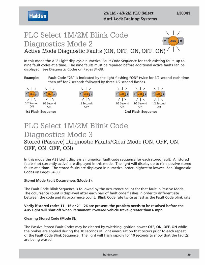
1/2 SecondON
1/2 SecondON
2 SecondsOFF
1/2 SecondON
1/2 SecondON
1/2 SecondON
1st Flash Sequence 2nd Flash Sequence
In this mode the ABS Light displays a numerical Fault Code Sequence for each existing fault, up to nine fault codes at a time. The nine faults must be repaired before additional active faults can be displayed. See Diagnostic Codes on Pages 34-38.
Example: Fault Code “23” is indicated by the light flashing “ON” twice for 1/2 second each time then off for 2 seconds followed by three 1/2 second flashes.
PLC Select 1M/2M Blink Code Diagnostics Mode 3Stored (Passive) Diagnostic Faults/Clear Mode (ON, OFF, ON, OFF, ON, OFF, ON)
In this mode the ABS Light displays a numerical fault code sequence for each stored fault. All storedfaults (not currently active) are displayed in this mode. The light will display up to nine passive stored faults at a time. The stored faults are displayed in numerical order, highest to lowest. See Diagnostic Codes on Pages 34-38.
Stored Mode Fault Occurrences (Mode 3):
The Fault Code Blink Sequence is followed by the occurrence count for that fault in Passive Mode. The occurrence count is displayed after each pair of fault code flashes in order to differentiate between the code and its occurrence count. Blink Code rate twice as fast as the Fault Code blink rate.
Verify if stored codes 11 - 16 or 21 - 26 are present, the problem needs to be resolved before the ABS Light will shut off when Permanent Powered vehicle travel greater than 6 mph.
Clearing Stored Code (Mode 3):
The Passive Stored Fault Codes may be cleared by switching ignition power OFF, ON, OFF, ON while the brakes are applied during the 10 seconds of light energization that occurs prior to each repeat of the Fault Code Blink Sequence. The light will flash rapidly for 10 seconds to show that the fault(s) are being erased.
2S/1M - 4S/2M PLC Select L30041 Anti-Lock Braking Systems
PLC Select 1M/2M Blink Code Diagnostics Mode 2Active Mode Diagnostic Faults (ON, OFF, ON, OFF, ON)
PLC Select 1M & haldex.com 29
1/2 SecondON
1/2 SecondON
2 SecondsOFF
1/2 SecondON
1/2 SecondON
1/2 SecondON
2 SecondsOFF
1/4 SecondON
1/4 SecondON
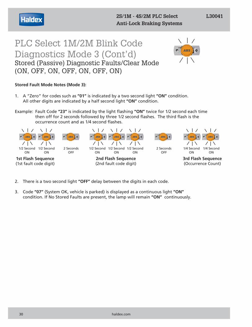
Stored Fault Mode Notes (Mode 3):
1. A “Zero” for codes such as “01” is indicated by a two second light “ON” condition. All other digits are indicated by a half second light “ON” condition.
Example: Fault Code “23” is indicated by the light flashing “ON” twice for 1/2 second each time then off for 2 seconds followed by three 1/2 second flashes. The third flash is the occurrence count and as 1/4 second flashes.
2. There is a two second light “OFF” delay between the digits in each code.
3. Code “07” (System OK, vehicle is parked) is displayed as a continuous light “ON” condition. If No Stored Faults are present, the lamp will remain “ON” continuously.
2S/1M - 4S/2M PLC Select L30041 Anti-Lock Braking Systems
PLC Select 1M/2M Blink Code Diagnostics Mode 3 (Cont’d)Stored (Passive) Diagnostic Faults/Clear Mode (ON, OFF, ON, OFF, ON, OFF, ON)
1st Flash Sequence(1st fault code digit)
2nd Flash Sequence(2nd fault code digit)
3rd Flash Sequence(Occurrence Count)
30 haldex.com
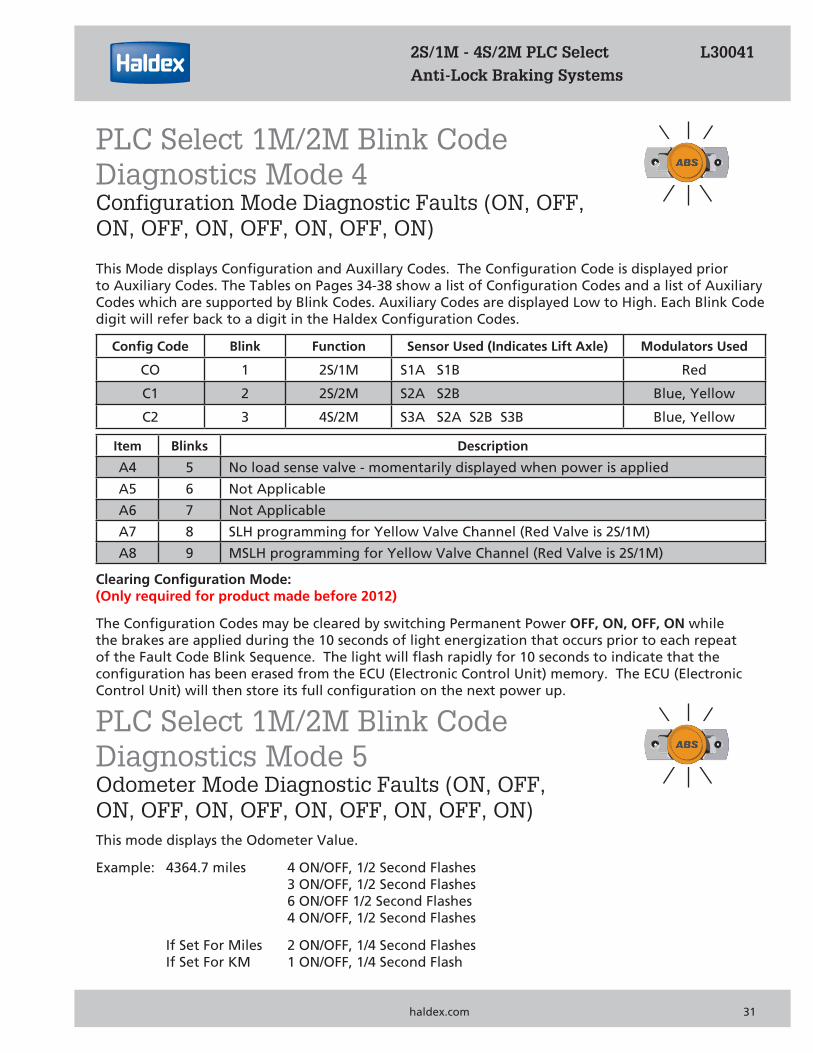
This Mode displays Configuration and Auxillary Codes. The Configuration Code is displayed prior to Auxiliary Codes. The Tables on Pages 34-38 show a list of Configuration Codes and a list of Auxiliary Codes which are supported by Blink Codes. Auxiliary Codes are displayed Low to High. Each Blink Code digit will refer back to a digit in the Haldex Configuration Codes.
Config Code Blink Function Sensor Used (Indicates Lift Axle) Modulators Used
CO 1 2S/1M S1A S1B Red
C1 2 2S/2M S2A S2B Blue, Yellow
C2 3 4S/2M S3A S2A S2B S3B Blue, Yellow
Item Blinks Description
A4 5 No load sense valve - momentarily displayed when power is applied
A5 6 Not Applicable
A6 7 Not Applicable
A7 8 SLH programming for Yellow Valve Channel (Red Valve is 2S/1M)
A8 9 MSLH programming for Yellow Valve Channel (Red Valve is 2S/1M)
Clearing Configuration Mode:(Only required for product made before 2012)
The Configuration Codes may be cleared by switching Permanent Power OFF, ON, OFF, ON while the brakes are applied during the 10 seconds of light energization that occurs prior to each repeat of the Fault Code Blink Sequence. The light will flash rapidly for 10 seconds to indicate that the configuration has been erased from the ECU (Electronic Control Unit) memory. The ECU (Electronic Control Unit) will then store its full configuration on the next power up.
2S/1M - 4S/2M PLC Select L30041 Anti-Lock Braking Systems
PLC Select 1M/2M Blink Code Diagnostics Mode 4Configuration Mode Diagnostic Faults (ON, OFF, ON, OFF, ON, OFF, ON, OFF, ON)
PLC Select 1M/2M Blink Code Diagnostics Mode 5Odometer Mode Diagnostic Faults (ON, OFF, ON, OFF, ON, OFF, ON, OFF, ON, OFF, ON)This mode displays the Odometer Value.
Example: 4364.7 miles 4 ON/OFF, 1/2 Second Flashes 3 ON/OFF, 1/2 Second Flashes 6 ON/OFF 1/2 Second Flashes 4 ON/OFF, 1/2 Second Flashes
If Set For Miles 2 ON/OFF, 1/4 Second Flashes If Set For KM 1 ON/OFF, 1/4 Second Flash
PLC Select 1M & haldex.com 31
Trailer TireScale Factor100T (Miles)
Scale Factor100T (km)
Scale Factor80T (Miles)
Scale Factor80T (km)
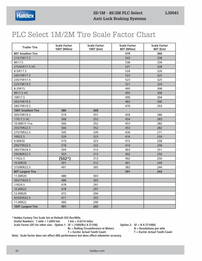
80T Smallest Tire 579 360 215/75R17.5 543 338 8R17.5 538 334 275/65R17.5 HC 527 328 8.5/R17.5 524 326 245/70R17.5 523 325 235/75R17.5 523 325 225/70R19.5 521 324 8.25R15 495 308 9R17.5 HC 495 308 10R17.5 490 304 265/70R19.5 483 300 285/70R19.5 470 293 100T Smallest Tire 580 360 305/70R19.5 574 357 459 286 11R17.5 HC 568 353 454 283 10.00R15 Tire 566 352 453 282 255/70R22.5 566 352 453 282 275/70R22.5 545 339 436 271 10R22.5 520 323 416 259 9.00R20 519 323 415 258 295/75R22.5 518 322 414 258 285/75R24.5 504 313 403 251 295/80R22.5 503 313 402 250 11R22.5 (502*) 313 402 250 10.00R20 501 312 401 249 315/80R22.5 491 305 383 244 80T Largest Tire 391 243 11.00R20 488 303 305/75R24.5 488 303 11R24.5 478 297 10.00R22 478 297 12.00R20 472 294 425/65R22.5 471 293 11.00R22 466 290 100T Largest Tire 391 243
* Haldex Factory Tire Scale Set at Default 502 Rev/Mile. Useful Numbers: 1 mile = 1.6093 km 1 km = 0.6214 miles Scale Factor (SF) for other size: Option 1: SF = (1000/Rc) X (T/100) Option 2: SF = N X (T/1000) Rc = Rolling Circumference in Meters N = Revolutions per mile T = Exciter Actual Tooth Count T = Exciter Actual Tooth CountNote: Scale factor does not affect ABS performance but does affect odometer accuracy.
2S/1M - 4S/2M PLC Select L30041 Anti-Lock Braking Systems
32 haldex.com
PLC Select 1M/2M Tire Scale Factor Chart
ABS Warning Light Stays On Permanently:
Upon power up of the ABS System (Permanently or Stoplight Power), the ABS Warning Lights should come “ON” for 3 seconds and then go “OFF”. If the ABS Warning Light stays “ON”, it may be caused by improper light wiring, or by a fault in the ABS System.
1. Check for Diagnostic Fault Codes. If anything other than a “07” is displayed, review the Troubleshooting Diagnostic Code Section on Pages 34-38 for possible solutions. After the problem is repaired, clear all stored faults and test again.2. If a “07” is displayed but there was a 11 - 16, or 21 - 26 fault stored in memory, correct the problem and drive the trailer or rotate the wheel affected >1 mph using Permanent Power to get the ABS Light to turn “OFF”.3. If a “07” is displayed, there are no faults stored in memory and the ABS Light is still “ON”, the ABS Light is wired incorrectly. Remove the main wire harness 5 Pin Connector at the ECU (Electronic Control Unit) and verify continuity between Pin “D”. Refer to Pin Out for ABS Power Cord on Page 18. The remaining light wire must be grounded to the trailer chassis or connected to the SAE J560 7-Way Connector ground wire. Check for continuity between the ABS Light wire and ground. Repair as necessary and retest.4. If the solenoid does not energize with a “CLICK, CLICK” when power is applied, or the diagnostic tool has nothing on the display, check power on the Blue or Red wire of the 7-Way Connector, as well as, the ABS Power Cord. Refer to Pin Out for ABS Power Cord on Page 18. Verify power source is >10 Volts when connected to ABS.
ABS Warning Light Does Not Illuminate:
1. Check the bulb to verify that is functional. If not functional, replace it and retest.2. Verify that there is power to the ECU (Electronic Control Unit) and the solenoid does energize with a “CLICK, CLICK” when power is applied. If not, disconnect the main wire harness 5 Pin Connector and check for positive power between either Stop Light Power with brakes applied or Permanent Power and ground. Refer to Pin Out for ABS Power Cord on Page 18. The voltage drop between the SAE J560 7-Way Connector and the ECU (Electronic Control Unit) should not exceed 2 Volts. If no power exists at either Stop Light or Permanent Power in reference to ground then check continuity from these pins to the SAE J560 7-Way Connector Red and Blue circuits. Make necessary repairs and retest. Verify power source is >10 Volts when connected to ABS.3. If the problem is still present, remove the main wire harness 5 Pin Connector at the ECU (Electronic Control Unit) and verify continuity between Pin “D”. Refer to Pin Out for ABS Power Cord on Page 18. The remaining light wire must be grounded to the trailer chassis or connected to the SAE J560 7-Way Connector ground wire. Check for continuity between the ABS Warning Light wire and ground. Repair as necessary and retest.
2S/1M - 4S/2M PLC Select L30041 Anti-Lock Braking Systems
PLC Select 1M & haldex.com 33
PLC Select 1M/2M TroubleshootingABS Warning Light
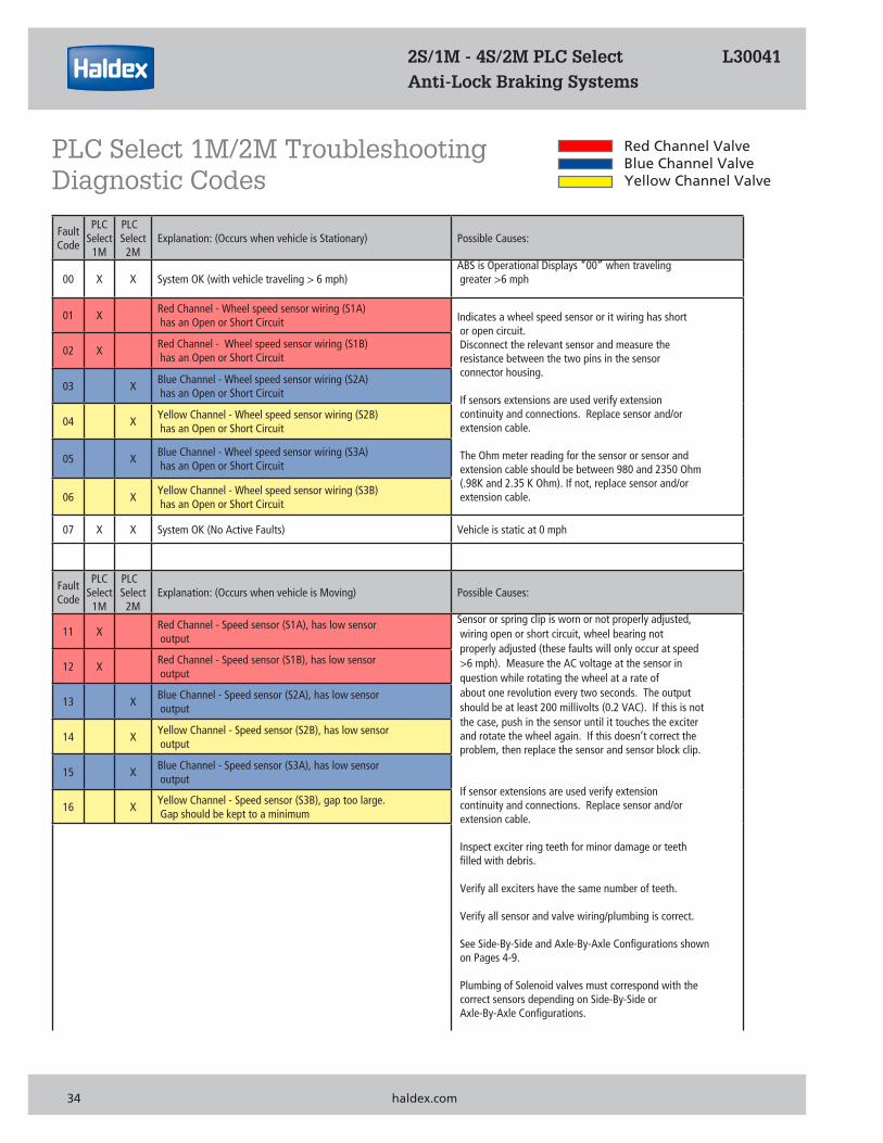
Red Channel ValveBlue Channel ValveYellow Channel Valve
FaultCode
PLCSelect
1M
PLCSelect
2M Explanation: (Occurs when vehicle is Stationary) Possible Causes:
00 X X System OK (with vehicle traveling > 6 mph) ABS is Operational Displays “00” when traveling greater >6 mph
01 X Red Channel - Wheel speed sensor wiring (S1A) has an Open or Short Circuit Indicates a wheel speed sensor or it wiring has short
or open circuit. Disconnect the relevant sensor and measure the resistance between the two pins in the sensor connector housing.
If sensors extensions are used verify extension continuity and connections. Replace sensor and/or extension cable.
The Ohm meter reading for the sensor or sensor and extension cable should be between 980 and 2350 Ohm (.98K and 2.35 K Ohm). If not, replace sensor and/or extension cable.
02 X Red Channel - Wheel speed sensor wiring (S1B) has an Open or Short Circuit
03 X Blue Channel - Wheel speed sensor wiring (S2A) has an Open or Short Circuit
04 X Yellow Channel - Wheel speed sensor wiring (S2B) has an Open or Short Circuit
05 X Blue Channel - Wheel speed sensor wiring (S3A) has an Open or Short Circuit
06 X Yellow Channel - Wheel speed sensor wiring (S3B) has an Open or Short Circuit
07 X X System OK (No Active Faults) Vehicle is static at 0 mph
FaultCode
PLCSelect
1M
PLCSelect
2M Explanation: (Occurs when vehicle is Moving) Possible Causes:
11 X Red Channel - Speed sensor (S1A), has low sensor output
Sensor or spring clip is worn or not properly adjusted, wiring open or short circuit, wheel bearing not properly adjusted (these faults will only occur at speed >6 mph). Measure the AC voltage at the sensor in question while rotating the wheel at a rate of about one revolution every two seconds. The output should be at least 200 millivolts (0.2 VAC). If this is not the case, push in the sensor until it touches the exciter and rotate the wheel again. If this doesn’t correct the problem, then replace the sensor and sensor block clip.
If sensor extensions are used verify extension continuity and connections. Replace sensor and/or extension cable.
Inspect exciter ring teeth for minor damage or teeth filled with debris.
Verify all exciters have the same number of teeth. Verify all sensor and valve wiring/plumbing is correct.
See Side-By-Side and Axle-By-Axle Configurations shown on Pages 4-9.
Plumbing of Solenoid valves must correspond with the correct sensors depending on Side-By-Side or Axle-By-Axle Configurations.
12 X Red Channel - Speed sensor (S1B), has low sensor output
13 X Blue Channel - Speed sensor (S2A), has low sensor output
14 X Yellow Channel - Speed sensor (S2B), has low sensor output
15 X Blue Channel - Speed sensor (S3A), has low sensor output
16 X Yellow Channel - Speed sensor (S3B), gap too large. Gap should be kept to a minimum
2S/1M - 4S/2M PLC Select L30041 Anti-Lock Braking Systems
PLC Select 1M/2M Troubleshooting Diagnostic Codes
34 haldex.com
FaultCode
PLCSelect
1M
PLCSelect
2M Explanation: (Occurs when vehicle is Moving) Possible Causes:
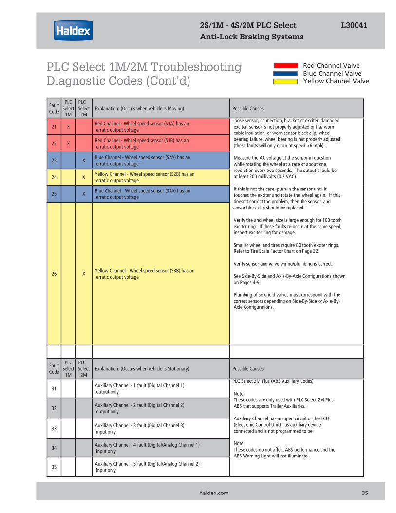
21 X Red Channel - Wheel speed sensor (S1A) has an erratic output voltage
Loose sensor, connection, bracket or exciter, damaged exciter, sensor is not properly adjusted or has worn cable insulation, or worn sensor block clip, wheel bearing failure, wheel bearing is not properly adjusted (these faults will only occur at speed >6 mph).
Measure the AC voltage at the sensor in question while rotating the wheel at a rate of about one revolution every two seconds. The output should be at least 200 millivolts (0.2 VAC). If this is not the case, push in the sensor until it touches the exciter and rotate the wheel again. If this doesn’t correct the problem, then the sensor, and sensor block clip should be replaced.
Verify tire and wheel size is large enough for 100 tooth exciter ring. If these faults re-occur at the same speed, inspect exciter ring for damage.
Smaller wheel and tires require 80 tooth exciter rings. Refer to Tire Scale Factor Chart on Page 32. Verify sensor and valve wiring/plumbing is correct.
See Side-By-Side and Axle-By-Axle Configurations shown on Pages 4-9.
Plumbing of solenoid valves must correspond with the correct sensors depending on Side-By-Side or Axle-By- Axle Configurations.
22 X Red Channel - Wheel speed sensor (S1B) has an erratic output voltage
23 X Blue Channel - Wheel speed sensor (S2A) has an erratic output voltage
24 X Yellow Channel - Wheel speed sensor (S2B) has an erratic output voltage
25 X Blue Channel - Wheel speed sensor (S3A) has an erratic output voltage
26 X Yellow Channel - Wheel speed sensor (S3B) has an erratic output voltage
FaultCode
PLCSelect
1M
PLCSelect
2M Explanation: (Occurs when vehicle is Stationary) Possible Causes:
31 Auxiliary Channel - 1 fault (Digital Channel 1) output only
PLC Select 2M Plus (ABS Auxiliary Codes)
Note: These codes are only used with PLC Select 2M Plus ABS that supports Trailer Auxiliaries.
Auxiliary Channel has an open circuit or the ECU (Electronic Control Unit) has auxiliary device connected and is not programmed to be.
Note: These codes do not affect ABS performance and the ABS Warning Light will not illuminate.
32 Auxiliary Channel - 2 fault (Digital Channel 2) output only
33 Auxiliary Channel - 3 fault (Digital Channel 3) input only
34 Auxiliary Channel - 4 fault (Digital/Analog Channel 1) input only
35 Auxiliary Channel - 5 fault (Digital/Analog Channel 2) input only
2S/1M - 4S/2M PLC Select L30041 Anti-Lock Braking Systems
Red Channel ValveBlue Channel ValveYellow Channel Valve
PLC Select 1M/2M Troubleshooting Diagnostic Codes (Cont’d)
haldex.com 35
FaultCode
PLCSelect
1M
PLCSelect
2M
Explanation: (Occurs when vehicle is Stationary or Moving)
Possible Causes:
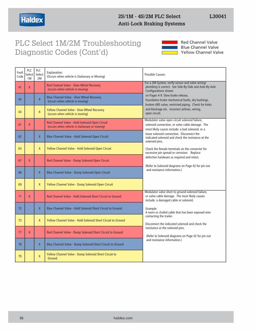
41 X Red Channel Valve - Slow Wheel Recovery (occurs when vehicle is moving)
For a 2M System, verify sensor and valve wiring/ plumbing is correct. See Side-By-Side and Axle-By-Axle Configurations shown on Pages 4-9. Slow brake release, foundation brake mechanical faults, dry bushings, broken ABS valve, restricted piping. Check for kinks and blockage etc. Incorrect airlines, wiring, open circuit.
42 X Blue Channel Valve - Slow Wheel Recovery (occurs when vehicle is moving)
43 X Yellow Channel Valve - Slow Wheel Recovery (occurs when vehicle is moving)
61 X Red Channel Valve - Hold Solenoid Open Circuit (occurs when vehicle is stationary or moving)
Modulator valve open circuit solenoid failure, solenoid connection, or valve cable damage. The most likely causes include: a bad solenoid, or a loose solenoid connection. Disconnect the indicated solenoid and check the resistance at the solenoid pins.
Check the female terminals on the connector for excessive pin spread or corrosion. Replace defective hardware as required and retest.
(Refer to Solenoid diagrams on Page 42 for pin out and resistance information.)
62 X Blue Channel Valve - Hold Solenoid Open Circuit
63 X Yellow Channel Valve - Hold Solenoid Open Circuit
67 X Red Channel Valve - Dump Solenoid Open Circuit
68 X Blue Channel Valve - Dump Solenoid Open Circuit
69 X Yellow Channel Valve - Dump Solenoid Open Circuit
71 X Red Channel Valve - Hold Solenoid Short Circuit to Ground Modulator valve short to ground solenoid failure, or valve cable damage. The most likely causes include: a damaged cable or solenoid.
Example: A worn or chafed cable that has been exposed wire contacting the trailer.
Disconnect the indicated solenoid and check the resistance at the solenoid pins.
(Refer to Solenoid diagrams on Page 42 for pin out and resistance information.)
72 X Blue Channel Valve - Hold Solenoid Short Circuit to Ground
73 X Yellow Channel Valve - Hold Solenoid Short Circuit to Ground
77 X Red Channel Valve - Dump Solenoid Short Circuit to Ground
78 X Blue Channel Valve - Dump Solenoid Short Circuit to Ground
79 X Yellow Channel Valve - Dump Solenoid Short Circuit to Ground
Red Channel ValveBlue Channel ValveYellow Channel Valve
2S/1M - 4S/2M PLC Select L30041 Anti-Lock Braking Systems
PLC Select 1M/2M Troubleshooting Diagnostic Codes (Cont’d)
36 haldex.com
FaultCode
PLCSelect
1M
PLCSelect
2M
Explanation: (Occurs when vehicle is Stationary or Moving)
Possible Causes:
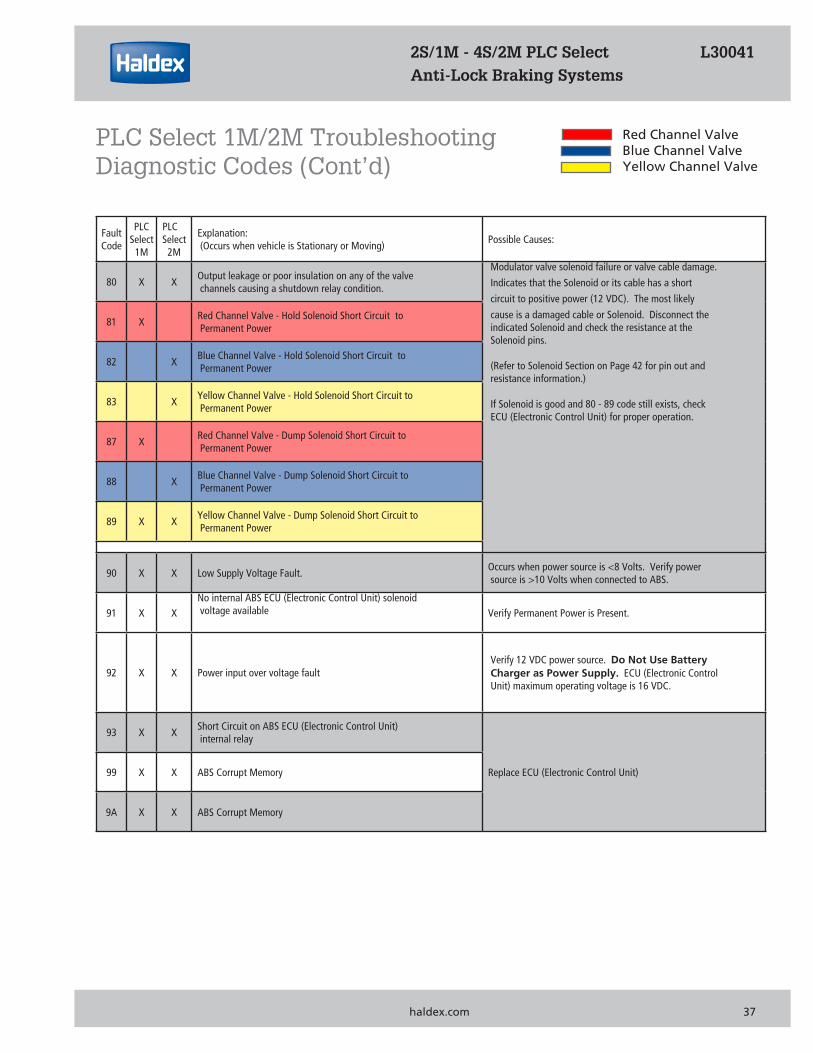
80 X X Output leakage or poor insulation on any of the valve channels causing a shutdown relay condition.
Modulator valve solenoid failure or valve cable damage.
Indicates that the Solenoid or its cable has a short
circuit to positive power (12 VDC). The most likely
cause is a damaged cable or Solenoid. Disconnect the indicated Solenoid and check the resistance at the Solenoid pins.
(Refer to Solenoid Section on Page 42 for pin out and resistance information.)
If Solenoid is good and 80 - 89 code still exists, check ECU (Electronic Control Unit) for proper operation.
81 X Red Channel Valve - Hold Solenoid Short Circuit to Permanent Power
82 X Blue Channel Valve - Hold Solenoid Short Circuit to Permanent Power
83 X Yellow Channel Valve - Hold Solenoid Short Circuit to Permanent Power
87 X Red Channel Valve - Dump Solenoid Short Circuit to Permanent Power
88 X Blue Channel Valve - Dump Solenoid Short Circuit to Permanent Power
89 X X Yellow Channel Valve - Dump Solenoid Short Circuit to Permanent Power
90 X X Low Supply Voltage Fault. Occurs when power source is <8 Volts. Verify power source is >10 Volts when connected to ABS.
91 X X No internal ABS ECU (Electronic Control Unit) solenoid voltage available Verify Permanent Power is Present.
92 X X Power input over voltage fault Verify 12 VDC power source. Do Not Use Battery Charger as Power Supply. ECU (Electronic Control Unit) maximum operating voltage is 16 VDC.
93 X X Short Circuit on ABS ECU (Electronic Control Unit) internal relay
Replace ECU (Electronic Control Unit)99 X X ABS Corrupt Memory
9A X X ABS Corrupt Memory
2S/1M - 4S/2M PLC Select L30041 Anti-Lock Braking Systems
Red Channel ValveBlue Channel ValveYellow Channel Valve
PLC Select 1M/2M Troubleshooting Diagnostic Codes (Cont’d)
haldex.com 37
FaultCode
PLCSelect
1M
PLCSelect
2M
Explanation: (Occurs when vehicle is Stationary or Moving)
Possible Causes:
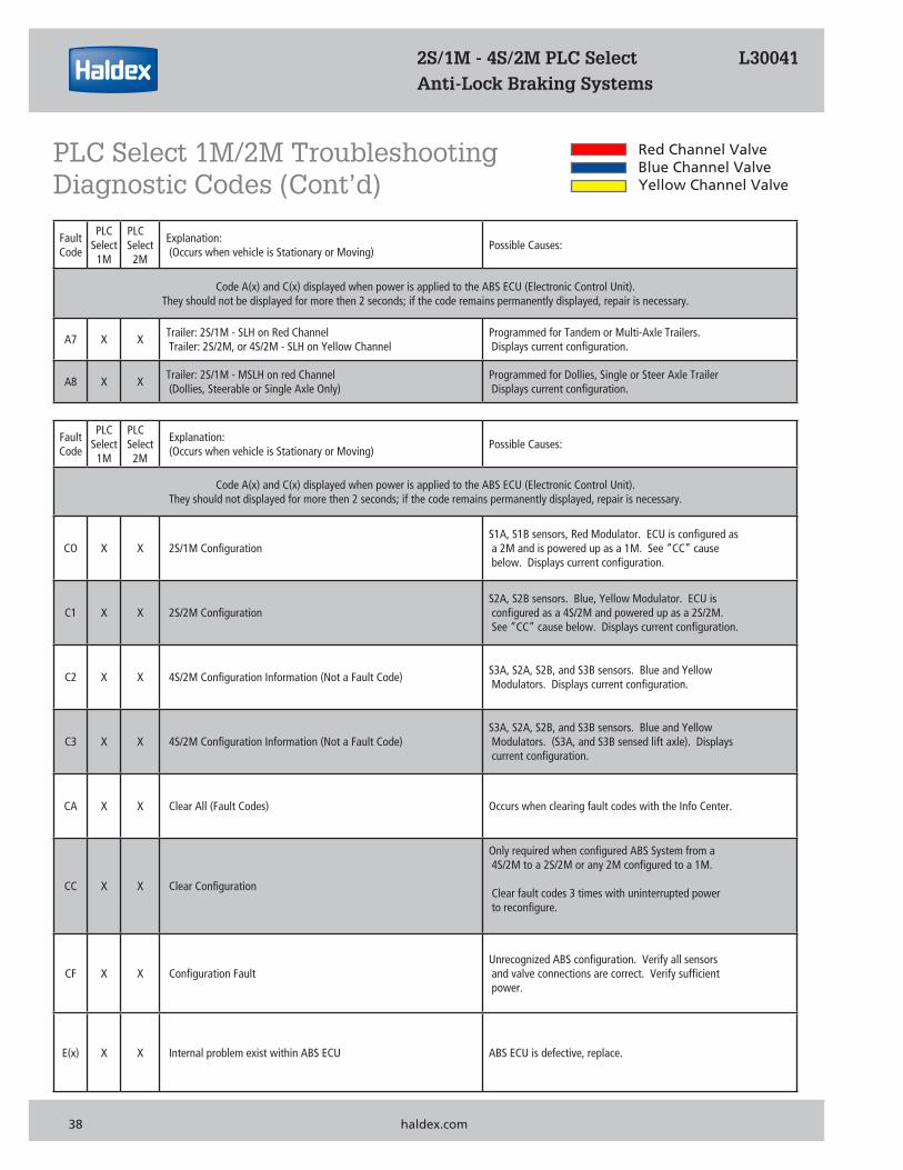
Code A(x) and C(x) displayed when power is applied to the ABS ECU (Electronic Control Unit). They should not be displayed for more then 2 seconds; if the code remains permanently displayed, repair is necessary.
A7 X X Trailer: 2S/1M - SLH on Red Channel Trailer: 2S/2M, or 4S/2M - SLH on Yellow Channel
Programmed for Tandem or Multi-Axle Trailers. Displays current configuration.
A8 X X Trailer: 2S/1M - MSLH on red Channel (Dollies, Steerable or Single Axle Only)
Programmed for Dollies, Single or Steer Axle Trailer Displays current configuration.
FaultCode
PLCSelect
1M
PLCSelect
2M
Explanation: (Occurs when vehicle is Stationary or Moving)
Possible Causes:
Code A(x) and C(x) displayed when power is applied to the ABS ECU (Electronic Control Unit). They should not displayed for more then 2 seconds; if the code remains permanently displayed, repair is necessary.
CO X X 2S/1M Configuration S1A, S1B sensors, Red Modulator. ECU is configured as a 2M and is powered up as a 1M. See “CC” cause below. Displays current configuration.
C1 X X 2S/2M Configuration S2A, S2B sensors. Blue, Yellow Modulator. ECU is configured as a 4S/2M and powered up as a 2S/2M. See “CC” cause below. Displays current configuration.
C2 X X 4S/2M Configuration Information (Not a Fault Code) S3A, S2A, S2B, and S3B sensors. Blue and Yellow Modulators. Displays current configuration.
C3 X X 4S/2M Configuration Information (Not a Fault Code) S3A, S2A, S2B, and S3B sensors. Blue and Yellow Modulators. (S3A, and S3B sensed lift axle). Displays current configuration.
CA X X Clear All (Fault Codes) Occurs when clearing fault codes with the Info Center.
CC X X Clear Configuration
Only required when configured ABS System from a 4S/2M to a 2S/2M or any 2M configured to a 1M. Clear fault codes 3 times with uninterrupted power to reconfigure.
CF X X Configuration Fault Unrecognized ABS configuration. Verify all sensors and valve connections are correct. Verify sufficient power.
E(x) X X Internal problem exist within ABS ECU ABS ECU is defective, replace.
Red Channel ValveBlue Channel ValveYellow Channel Valve
2S/1M - 4S/2M PLC Select L30041 Anti-Lock Braking Systems
PLC Select 1M/2M Troubleshooting Diagnostic Codes (Cont’d)
38 haldex.com
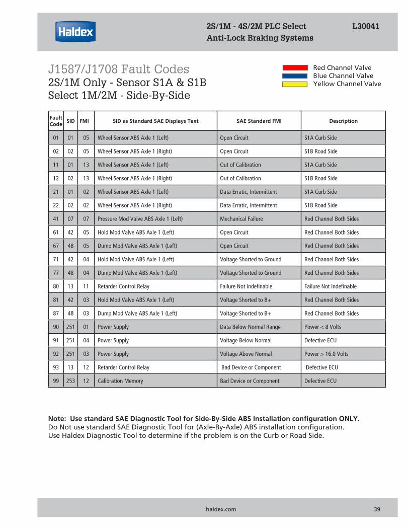
FaultCode
SID FMI SID as Standard SAE Displays Text SAE Standard FMI Description
01 01 05 Wheel Sensor ABS Axle 1 (Left) Open Circuit S1A Curb Side
02 02 05 Wheel Sensor ABS Axle 1 (Right) Open Circuit S1B Road Side
11 01 13 Wheel Sensor ABS Axle 1 (Left) Out of Calibration S1A Curb Side
12 02 13 Wheel Sensor ABS Axle 1 (Right) Out of Calibration S1B Road Side
21 01 02 Wheel Sensor ABS Axle 1 (Left) Data Erratic, Intermittent S1A Curb Side
22 02 02 Wheel Sensor ABS Axle 1 (Right) Data Erratic, Intermittent S1B Road Side
41 07 07 Pressure Mod Valve ABS Axle 1 (Left) Mechanical Failure Red Channel Both Sides
61 42 05 Hold Mod Valve ABS Axle 1 (Left) Open Circuit Red Channel Both Sides
67 48 05 Dump Mod Valve ABS Axle 1 (Left) Open Circuit Red Channel Both Sides
71 42 04 Hold Mod Valve ABS Axle 1 (Left) Voltage Shorted to Ground Red Channel Both Sides
77 48 04 Dump Mod Valve ABS Axle 1 (Left) Voltage Shorted to Ground Red Channel Both Sides
80 13 11 Retarder Control Relay Failure Not Indefinable Failure Not Indefinable
81 42 03 Hold Mod Valve ABS Axle 1 (Left) Voltage Shorted to B+ Red Channel Both Sides
87 48 03 Dump Mod Valve ABS Axle 1 (Left) Voltage Shorted to B+ Red Channel Both Sides
90 251 01 Power Supply Data Below Normal Range Power < 8 Volts
91 251 04 Power Supply Voltage Below Normal Defective ECU
92 251 03 Power Supply Voltage Above Normal Power > 16.0 Volts
93 13 12 Retarder Control Relay Bad Device or Component Defective ECU
99 253 12 Calibration Memory Bad Device or Component Defective ECU
Note: Use standard SAE Diagnostic Tool for Side-By-Side ABS Installation configuration ONLY. Do Not use standard SAE Diagnostic Tool for (Axle-By-Axle) ABS installation configuration. Use Haldex Diagnostic Tool to determine if the problem is on the Curb or Road Side.
2S/1M - 4S/2M PLC Select L30041 Anti-Lock Braking Systems
Red Channel ValveBlue Channel ValveYellow Channel Valve
J1587/J1708 Fault Codes2S/1M Only - Sensor S1A & S1BSelect 1M/2M - Side-By-Side
haldex.com 39
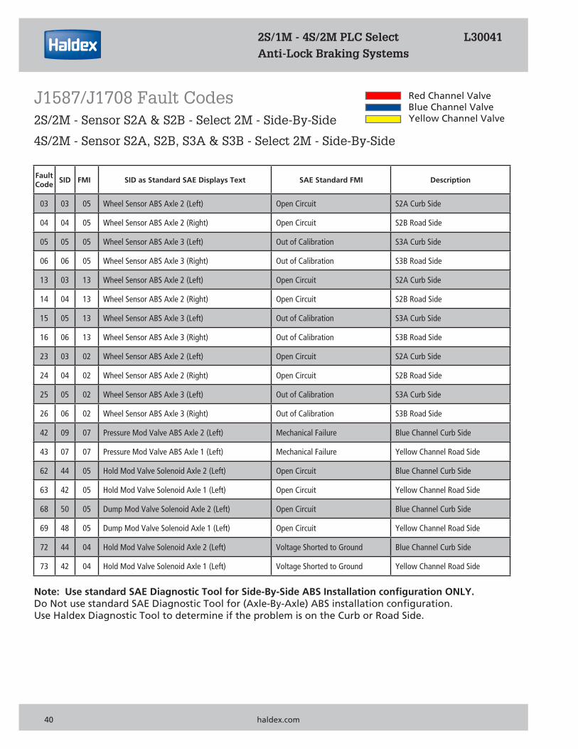
FaultCode
SID FMI SID as Standard SAE Displays Text SAE Standard FMI Description
03 03 05 Wheel Sensor ABS Axle 2 (Left) Open Circuit S2A Curb Side
04 04 05 Wheel Sensor ABS Axle 2 (Right) Open Circuit S2B Road Side
05 05 05 Wheel Sensor ABS Axle 3 (Left) Out of Calibration S3A Curb Side
06 06 05 Wheel Sensor ABS Axle 3 (Right) Out of Calibration S3B Road Side
13 03 13 Wheel Sensor ABS Axle 2 (Left) Open Circuit S2A Curb Side
14 04 13 Wheel Sensor ABS Axle 2 (Right) Open Circuit S2B Road Side
15 05 13 Wheel Sensor ABS Axle 3 (Left) Out of Calibration S3A Curb Side
16 06 13 Wheel Sensor ABS Axle 3 (Right) Out of Calibration S3B Road Side
23 03 02 Wheel Sensor ABS Axle 2 (Left) Open Circuit S2A Curb Side
24 04 02 Wheel Sensor ABS Axle 2 (Right) Open Circuit S2B Road Side
25 05 02 Wheel Sensor ABS Axle 3 (Left) Out of Calibration S3A Curb Side
26 06 02 Wheel Sensor ABS Axle 3 (Right) Out of Calibration S3B Road Side
42 09 07 Pressure Mod Valve ABS Axle 2 (Left) Mechanical Failure Blue Channel Curb Side
43 07 07 Pressure Mod Valve ABS Axle 1 (Left) Mechanical Failure Yellow Channel Road Side
62 44 05 Hold Mod Valve Solenoid Axle 2 (Left) Open Circuit Blue Channel Curb Side
63 42 05 Hold Mod Valve Solenoid Axle 1 (Left) Open Circuit Yellow Channel Road Side
68 50 05 Dump Mod Valve Solenoid Axle 2 (Left) Open Circuit Blue Channel Curb Side
69 48 05 Dump Mod Valve Solenoid Axle 1 (Left) Open Circuit Yellow Channel Road Side
72 44 04 Hold Mod Valve Solenoid Axle 2 (Left) Voltage Shorted to Ground Blue Channel Curb Side
73 42 04 Hold Mod Valve Solenoid Axle 1 (Left) Voltage Shorted to Ground Yellow Channel Road Side
2S/1M - 4S/2M PLC Select L30041 Anti-Lock Braking Systems
Red Channel ValveBlue Channel ValveYellow Channel Valve
J1587/J1708 Fault Codes2S/2M - Sensor S2A & S2B - Select 2M - Side-By-Side
4S/2M - Sensor S2A, S2B, S3A & S3B - Select 2M - Side-By-Side
Note: Use standard SAE Diagnostic Tool for Side-By-Side ABS Installation configuration ONLY. Do Not use standard SAE Diagnostic Tool for (Axle-By-Axle) ABS installation configuration. Use Haldex Diagnostic Tool to determine if the problem is on the Curb or Road Side.
40 haldex.com
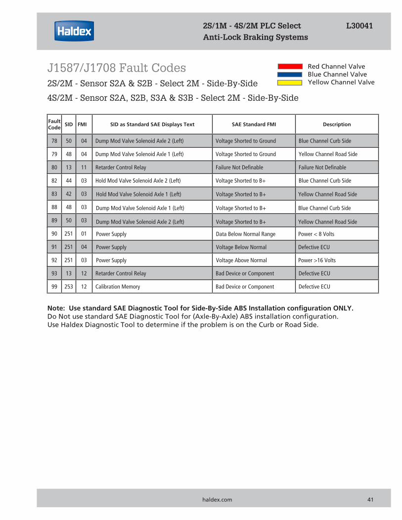
FaultCode
SID FMI SID as Standard SAE Displays Text SAE Standard FMI Description
78 50 04 Dump Mod Valve Solenoid Axle 2 (Left) Voltage Shorted to Ground Blue Channel Curb Side
79 48 04 Dump Mod Valve Solenoid Axle 1 (Left) Voltage Shorted to Ground Yellow Channel Road Side
80 13 11 Retarder Control Relay Failure Not Definable Failure Not Definable
82 44 03 Hold Mod Valve Solenoid Axle 2 (Left) Voltage Shorted to B+ Blue Channel Curb Side
83 42 03
88 48 03
89 50 03
90 251 01
91 251 04
92 251 03
93 13 12 Retarder Control Relay Bad Device or Component Defective ECU
99 253 12 Calibration Memory Bad Device or Component Defective ECU
2S/1M - 4S/2M PLC Select L30041 Anti-Lock Braking Systems
Red Channel ValveBlue Channel ValveYellow Channel Valve
J1587/J1708 Fault Codes2S/2M - Sensor S2A & S2B - Select 2M - Side-By-Side
4S/2M - Sensor S2A, S2B, S3A & S3B - Select 2M - Side-By-Side
Note: Use standard SAE Diagnostic Tool for Side-By-Side ABS Installation configuration ONLY. Do Not use standard SAE Diagnostic Tool for (Axle-By-Axle) ABS installation configuration. Use Haldex Diagnostic Tool to determine if the problem is on the Curb or Road Side.
haldex.com 41
2S/1M - 4S/2M PLC Select L30041 Anti-Lock Braking Systems
Hold Mod Valve Solenoid Axle 1 (Left) Voltage Shorted to B+ Yellow Channel Road Side
Dump Mod Valve Solenoid Axle 1 (Left) Voltage Shorted to B+ Blue Channel Curb Side
Dump Mod Valve Solenoid Axle 2 (Left) Voltage Shorted to B+ Yellow Channel Road Side
Power Supply Data Below Normal Range Power < 8 Volts
Power Supply Voltage Below Normal Defective ECU
Power Supply Voltage Above Normal Power >16 Volts
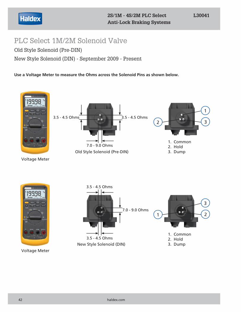
Use a Voltage Meter to measure the Ohms across the Solenoid Pins as shown below.
Old Style Solenoid (Pre-DIN)
1
32
1. Common2. Hold3. Dump
Voltage Meter
Voltage Meter
New Style Solenoid (DIN)
3
21
1. Common2. Hold3. Dump
3.5 - 4.5 Ohms
7.0 - 9.0 Ohms
3.5 - 4.5 Ohms
2S/1M - 4S/2M PLC Select L30041 Anti-Lock Braking Systems
PLC Select 1M/2M Solenoid ValveOld Style Solenoid (Pre-DIN)
New Style Solenoid (DIN) - September 2009 - Present
42 haldex.com
7.0 - 9.0 Ohms
3.5 - 4.5 Ohms3.5 - 4.5 Ohms
2S/1M - 4S/2M PLC Select L30041 Anti-Lock Braking Systems
Technical Support
haldex.com 43
2S/1M - 4S/2M PLC Select L30041 Anti-Lock Braking Systems
United States
Haldex Brake Products Corporation 10930 North Pomona Avenue Kansas City, Missouri 64513 Technical Service & Engineering Support +1 (800) 643-2374 (Press 2) or Ext. 2337
Canada Haldex Limited/Haldex Limitée 500 Pinebush Road, Unit 1 Cambridge, ON N1T 0A5 Technical Service & Engineering Support +1 (800) 267-9247 (Press 2)
Notes: 2S/1M - 4S/2M PLC Select L30041 Anti-Lock Braking Systems
44 haldex.com
Notes
this page has been left blank intentionally
2S/1M - 4S/2M PLC Select L30041 Anti-Lock Braking Systems
haldex.com 45
2S/1M - 4S/2M PLC Select L30041 Anti-Lock Braking Systems

With more than 100 years of intensely focused innovation, Haldex holds unrivaled expertise in brake systems and air suspension systems for heavy
trucks, trailers and buses. We live and breathe our business, delivering robust, technically superior solutions born from deep insight into our customers’ reality.
By concentrating on our core competencies and following our strengths and passions, we combine both the operating speed and flexibility required by the market. Collaborative innovation is not only the essence of our products - it is also our philosophy. Our employees, spread on four continents, are constantly challenging the conventional and strive to ensure that the products we deliver
create unique value for our customers and all end-users.
United States 816-891-2470Canada 519-621-6722Mexico 52-81-81569500
To learn more, contact your Haldex sales professional.
L30041US Rev. 3/20
WEB ONLY
For additional contact information or to learn more about Haldex, please visit Haldex.com