Embed Size (px)
Citation preview

Please leave these instructions with the customer
IdentityThermostatic digital shower control panel with diverter - wall mounted
If installing product on a pump system, installer must ensure that a negative/universal head pump is used. Failure to comply with this will result in incorrect operation.
VadoWedmore Road, Cheddar, Somerset, England BS27 3EB
tel 01934 744466. fax 01934 [email protected]
www.vado-uk.com
Guarantee
Customer/technical services
For any technical or installation queries please contact Vado on 01934 745163.
GUARANTEE REGISTRATIONNAME
ADDRESS
RETAILERADDRESS
PURCHASE DATEPRODUCT DESCRIPTIONWHO INSTALLED THE PRODUCT?FOR VADO USE
POSTCODE
POSTCODEARTICLE NUMBER (SEE BOX)
RETAILER PLUMBER BUILDER SELF
This product is guaranteed against manufacturing defects from the date of purchase until the expiry of the relevant guarantee period shown below.
The guarantee is only valid if:-
1. The product has been installed, used and maintained in accordance with Vado’s instructions and subjected to normal use only.
2. The defect is not due to use of an unsuitable or inadequate water or power supply.
3. The defect is not due to accident, misuse, neglect or repair other than by Vado or Vado authorised agents or damage caused by foreign objects or substances.
4. We have received from you the completed Guarantee Registration Form. Vado accepts no responsibility for any forms lost in the post and returns by registered means is therefore recommended.
Under this guarantee (which is non-transferable) Vado will, at its option, repair or replace free of charge any product (or replacement part) found to be defective. The guarantee does not extend to any consequential loss or damage. After repair or replacement the relevant guarantee period will be calculated from the original date of purchase.
The relevant guarantee periods are:-
1. Twelve years on chrome finish products.
2. Six years on Vado Identity products.
3. Three years on all other products with the exception of Stuart Turner Pumps which carry a 2 year Guarantee on Monsoon Range and 1 Year Guarantee on Showermate Range.
All claims under the guarantee must be submitted in writing to the person who supplied the product to you and must be received no later than the last day of the relevant guarantee period. All claims must be accompanied by proof of purchase (sales receipt or delivery note).
Vado operates a policy of continuous product development and therefore reserves the right to change the product, packaging and documentation specifications without notice.
This guarantee is in addition to and does not affect your statutory rights as a consumer.
Installation & maintenance instructions

Important - please read
2 11
Installers/users notes
Please read these instructions carefully before starting installation and keep for future reference.Remove all packaging and check the product for missing parts or damage before starting installation.Remove all packing materials and dispose of correctly.To avoid risk of suffocation to children or animals, dispose of the plastic bags correctly.Any alterations made to this product and fittings may infringe water and electrical regulations and will invalidate the guarantee.Under no circumstances, should the lid to the control box be removed. Removal of the lid, will invalidate any guarantee and carries risk of shock (240V).If installing in an enclosed environment, access should be left for servicing and maintenance. Please note this includes access to the cables. No costs relating to inadequate access can be accepted.All electrical connections and alterations should be carried out by a qualified electrician and be in compliance with Part P regulations.
Electrical ConnectionsAll electrical connections should be carried out by a qualified electrician.The installation must comply with current NICEIC regulations and to the requirements of BS7671 (Requirements for electrical installations).Please ensure that all exposed metal is supplementary bonded.Always switch off the power at the main consumer unit and isolate the electrical supply before making any electrical connections.This appliance is to be fitted with the relevant RCD protection.
Plumbing ConnectionsThe installation must comply with all Local/National Water Supply Authority Regulations/Byelaws and Building and Plumbing (UK:BS6700) Regulations.This mixer valve is suitable for any water system, provided minimum water pressure is met. Where connections are made to the mains cold water supply, WRC approved single check valves must be fitted to both hot and cold inlets. This is a stated requirement of Water Supply (Water Fittings) Regulations 1999 Schedule 2, Section 15.Before making any inlet pipe connections, all supply pipes MUST be thoroughly flushed to remove debris. Failure to do so could result in damage or low flow from the mixer unit. Water Supply (Water Fittings) Regulations 1999 Schedule 2 Section 13.The fitting of isolating valves to the inlet feeds is advised for ease of maintenance.Please take great care when installing this mixer not to damage its surface.Note: When pressure is higher than 5 bar a pressure reducer is required to be fitted before the valve.

Declaration of Conformity
The Identity range of digital showering listed below, complies with the essential requirements of the following EEC Directives;
2006/95/EC – The Low Voltage Directive2004/108/EC – The Electromagnetic Compatibility Directive
And is in conformity to the applicable requirements to the following standards;
EN 60335-1:2012 – Household and similar electrical appliances – safety – general requirements
EN 55014-1:2006+A1:2009 – Electromagnetic compatibility – Requirements for household appliances, electric tools and similar apparatus – part 1: Emission EN 61000-3-2:2006 – Electromagnetic compatibility – Limits for harmonic
current emissionsEN 61000-3-3:2008 – Electromagnetic compatibility – Limitation of voltage
changes, voltages fluctuations and flicker in public low-voltage supply systemsEN 55014-2:1997+A1:2001+A2:2008 – Electromagnetic compatibility –
Requirements for household appliances, electric tools and similar apparatus – part 2: Immunity – product family standard
Model: IDE-145-C/P, IDE-147A-C/P
Authorised signature
Vado, Wedmore Road, Cheddar, Somerset, BS27 3EB
10 3
Zone 1 Zone 1
Zone 2Zone 2Zone 2
Zone 2
60cm 60cm60cm 75cm
225cm
Zone 2
Zone 1
Zone 2
60cmradius
60cm
Zone 2
Zone 2
Zone 0 - Inside the Bath or Shower.Zone 1 - Area above the Bath or Shower tray to an height of 2.25m (minimum IP Rating of IPX4 is required alongside RCD protection).Zone 2 - Area outside of Zone 1 (minimum IP Rating of IPX4 is required).
All Vado identity showering products are IPX4 rated and are suitable for installation in zone 1 and beyond. The diagram below illustrates this zonal concept and must be followed to ensure safe installation of electrical bathroom products.
Important
Name: Adam MaleinPosition: Approvals and Compliance Officer
Declaration of Conformity
13
4 9
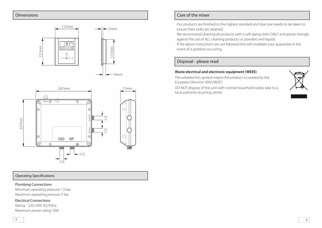
Dimensions
Operating Specifications
Plumbing Connections Minimum operating pressure 1.5 barMaximum operating pressure 5 bar
Electrical ConnectionsRating - 220-240V AC/50HzMaximum power rating 16W
Waste electrical and electronic equipment (WEEE)The wheeled bin symbol means the product is covered by the European Directive 2002/96/EC.
DO NOT dispose of this unit with normal household waste, take to a local authority recycling centre.
Disposal - please read
Care of the mixer
Our products are finished to the highest standard and due care needs to be taken to ensure their looks are retained.We recommend cleaning all products with a soft damp cloth ONLY and advise strongly against the use of ALL cleaning products i.e. powders and liquids.If the above instructions are not followed this will invalidate your guarantee in the event of a problem occurring.
COLD HOT
267mm
131m
m
112mm7mm
77mm
227m
m
1/2
117m
m
1/2
1/2
1/2
14mm
8 5
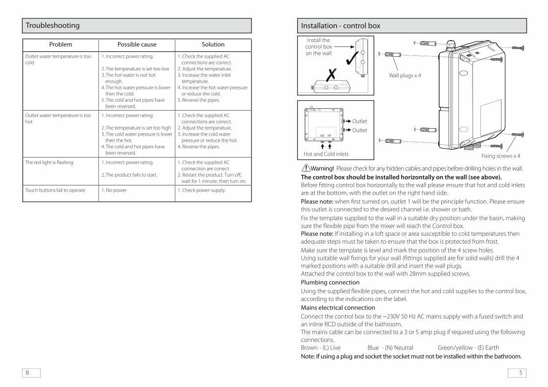
Installation - control box Troubleshooting
Problem Possible cause Solution
Outlet water temperature is too cold
1. Incorrect power rating.
2. The temperature is set too low3. The hot water is not hot
enough.4. The hot water pressure is lower
then the cold.5. The cold and hot pipes have
been reversed.
1. Check the supplied AC connections are correct.
2. Adjust the temperature.3. Increase the water inlet
temperature.4. Increase the hot water pressure
or reduce the cold.5. Reverse the pipes.
Outlet water temperature is too hot
1. Incorrect power rating.
2. The temperature is set too high3. The cold water pressure is lower
then the hot.4. The cold and hot pipes have
been reversed.
1. Check the supplied AC connections are correct.
2. Adjust the temperature.3. Increase the cold water
pressure or reduce the hot.4. Reverse the pipes.
The red light is flashing 1. Incorrect power rating.
2. The product fails to start.
1. Check the supplied AC connection are correct.
2. Restart the product. Turn off, wait for 1 minute, then turn on.
Touch buttons fail to operate 1. No power 1. Check power supply.
Wall plugs x 4
Fixing screws x 4
Warning! Please check for any hidden cables and pipes before drilling holes in the wall.The control box should be installed horizontally on the wall (see above). Before fitting control box horizontally to the wall please ensure that hot and cold inlets are at the bottom, with the outlet on the right hand side.Please note: when first turned on, outlet 1 will be the principle function. Please ensure this outlet is connected to the desired channel i.e. shower or bath.Fix the template supplied to the wall in a suitable dry position under the basin, making sure the flexible pipe from the mixer will reach the Control box. Please note: If installing in a loft space or area susceptible to cold temperatures then adequate steps must be taken to ensure that the box is protected from frost.Make sure the template is level and mark the position of the 4 screw holes. Using suitable wall fixings for your wall (fittings supplied are for solid walls) drill the 4 marked positions with a suitable drill and insert the wall plugs. Attached the control box to the wall with 28mm supplied screws.Plumbing connectionUsing the supplied flexible pipes, connect the hot and cold supplies to the control box, according to the indications on the label.Mains electrical connectionConnect the control box to the ~230V 50 Hz AC mains supply with a fused switch and an inline RCD outside of the bathroom. The mains cable can be connected to a 3 or 5 amp plug if required using the following connections. Brown - (L) Live Blue - (N) Neutral Green/yellow - (E) EarthNote: If using a plug and socket the socket must not be installed within the bathroom.
COLD HOT
Hot and Cold inlets
Outlet
Outlet
Install the control box on the wall

6 7
Installation - control panel
Signal cable from control panel
Signal cable from control box
Flats
Fixing ring
Unclip the cover from the bottom of the control panel and lift away from the top.
In the required position prepare a recess in the wall 98mm x 117mm and by 30mm deep from the final finish wall surface.
Fix the box in position making sure it is level and flush with the finished wall surface.
Bring the end of the extension lead coming from the control box through one of the holes in the box and connect to the lead coming from the control panel. Line up flats on both connectors and push together, screw on the ring to secure together.
Push the connector into the recess and the control panel into the box, secure in position with the 4 x 16mm screws.
Place the cover over the top of the control panel and clip onto the bottom.
Box
Screws
Cover
Cover
Control panel
Connector
Control panel
Operation
The mixer has 5 steps for the flow control and the temperature ranges from 25°C to 46°C.When the mixer is first commissioned the flow control is set on the 2nd step, and the temperature control is pre-set to 38°.If no keys have been pressed for 15 minutes the mixer will automatically switch off.
Touch button LED colours
Light status (colour) Mixer functions
Red light flashed for 3 seconds Mixer is starting
Blue colour Outlet water temperature <34°
Purple colour Outlet water temperature <40°
Red colour Outlet water temperature over 40°
Red light flashed for 0.5 seconds Product has malfunctioned
On/Off
Flow rate (-) decrease Temperature (+) increase
Flow rate (+) increase Temperature (-) decrease
Symbol Description Function descriptions
On and OffEach touch of the button switches the mixer on/off, each touch of the button a buzzer is heard. When on the panel LEDs will light accordingly.
Flow rate (-)When switched on - At each touch of the button the flow is decreased accordingly and a buzzer sound is heard.
Flow rate (+)When switched on - At each touch of the button the flow is increased accordingly and a buzzer sound is heard.
Diverts the flowEach touch of the button diverts the mixer between outlet 1 and outlet 2, each touch of the button a buzzer is heard. When on the panel LEDs will light accordingly. A symbol will show on the LCD screen.
Temperature (-)When switched on - At each touch of the button the temperature is decreased accordingly and a buzzer sound is heard.
Temperature (+)When switched on - At each touch of the button the temperature is increased accordingly and a buzzer sound is heard.
Diverter