Embed Size (px)
Citation preview

Cisco ME 3400E EtOL-16447-01
C H A P T E R 3
Installing and Removing AC- and DC-Power-Supply ModulesThis chapter provides the installation and removal instructions for the AC- and DC-power-supply modules for the Cisco ME 3400E-24TS-M and the Cisco ME 3400EG-12CS-M. Your switch ships with at least one power-supply module installed, either AC or DC, depending on your order. The power-supply modules are field-replaceable units (FRUs).
For translations of the safety warnings in this chapter, see the Regulatory Compliance and Safety Information for the Cisco ME 3400E Switch on the documentation CD and also on Cisco.com.
• Product Overview, page 3-1
• Power-Supply Module Installation, page 3-4
• Power Supply Settings, page 3-17
Product OverviewThis section gives an overview of the AC- and DC-power-supply modules.
• Power-Supply Module Description, page 3-1
• Handle-Side Description, page 3-2
• Connector-Side Description, page 3-4
Power-Supply Module Description
The 80-W AC-power-supply module is an autoranging unit that supports input voltages between 85 and 264 VAC. The DC-power-supply module has dual input feeds (A and B) and supports input voltages between –36 to –72 VDC for telecom applications and +18 to +36 VDC for industrial applications.
Table 3-1 Power-Supply Module Model Numbers and Descriptions
Model number Description
ME34X-PWR-AC AC-power-supply and fan module.
ME34X-PWR-DC DC-power-supply and fan module.
ME34X-PWR-BLANK= Spare blank cover for power-supply and fan module slot.
3-1hernet Access Switch Hardware Installation Guide

Chapter 3 Installing and Removing AC- and DC-Power-Supply ModulesProduct Overview
The AC-power-supply modules ship with a power cord to connect to an AC-power outlet. The DC-power-supply module ships with a terminal block to be wired for DC-power outlet connections.
Each power supply is cooled by internal fans. For maximum efficiency, at least two of the four fans should be operational in a warm environment. A fan failure triggers an alarm. When a fan fails, replace the power supply immediately.
You can order the generic AC-power cord (part number CAB-AC).
Handle-Side Description
Figure 3-1 80-W AC-Power-Supply Module Handle Side
1 Power-supply module 3 Extraction handle
2 PSU OK LED28
0822
PSU OK
AC
1
3
2
3-2Cisco ME 3400E Ethernet Access Switch Hardware Installation Guide
OL-16447-01

Chapter 3 Installing and Removing AC- and DC-Power-Supply ModulesProduct Overview
Figure 3-2 80-W DC-Power-Supply Module Handle Side
Figure 3-3 shows the DC-power-supply module PSU OK LED and the DC-voltage selector.
• For telecom applications (–36 to –72 VDC), set the DC-voltage selector to –48 VDC.
• For industrial applications (+18 to +36 VDC), set the DC-voltage selector to +24 VDC.
Figure 3-3 DC-Voltage Selector
The PSU OK LED on the AC-power-supply module looks the same as the one in Figure 3-3. The AC-power-supply module does not have a voltage selector.
1 Power-supply module 3 DC-power-supply voltage switch
2 PSU OK LED 4 Extraction handle
2808
23
PSU OK+24V -48V
DC
1
2 3
4
PSU OK+24V -48V
2808
24
3-3Cisco ME 3400E Ethernet Access Switch Hardware Installation Guide
OL-16447-01

Chapter 3 Installing and Removing AC- and DC-Power-Supply ModulesPower-Supply Module Installation
Connector-Side DescriptionFigure 3-4 shows the connector side of the power-supply module, which connects to the switch rear panel through its power-supply slot.
Figure 3-4 Power-Supply Module Connector Side
Power-Supply Module Installation• Tools and Equipment, page 3-5
• Installation Guidelines, page 3-5
• Installing an AC-Power-Supply Module, page 3-6
• Installing a DC-Power-Supply Module, page 3-8
Table 3-2 PSU OK LED Descriptions
AC-Power-Supply Module
LED Description
Off No input power.
Green Operating normally. Input, 12-V output, and both fans OK.
Red Fault detected: 12-V output, fan failure, or input out of range.
DC-Power-Supply Module
LED Description
Off No input power.
Green Operating normally. Input, 12-V output, and both fans OK.
Red Fault detected: 12-V output, fan failure, or input out of range.
1 Fans 2 Connector pins
2808
29
1
2
3-4Cisco ME 3400E Ethernet Access Switch Hardware Installation Guide
OL-16447-01
Chapter 3 Installing and Removing AC- and DC-Power-Supply ModulesPower-Supply Module Installation
Tools and EquipmentObtain these necessary tools and equipment:
• Ratcheting torque screwdriver with a number-2 Phillips head that exerts up to 15 inch-pounds (in-lb) of pressure.
• Power-supply power-cord retainer in the switch accessory kit.
Installation GuidelinesObserve these guidelines when you install a power-supply module:
• Do not force the power-supply module into the slot. This can damage the pins on the switch if they are not aligned with the unit.
• A power-supply module that is only partially connected to the switch can disrupt the system operation.
• Turn off switch power before you install the module.
• Verify that you are using the correct power cord.
Warning Blank faceplates (filler panels) serve three important functions: they prevent exposure to hazardous voltages and currents inside the chassis; they contain electromagnetic interference (EMI) that might disrupt other equipment; and they direct the flow of cooling air through the chassis. Do not operate the system unless all cards and faceplates are in place. Statement 156
Warning Do not reach into a vacant slot or chassis while you install or remove a module or a fan. Exposed circuitry could constitute an energy hazard. Statement 206
Warning Only trained and qualified personnel should be allowed to install, replace, or service this equipment. Statement 1030
Warning Do not work on the system or connect or disconnect cables during periods of lightning activity. Statement 1001
Caution To prevent overheating and to maintain proper air flow, either a power-supply module or a blank cover must be installed in each power-supply module slot at all times. Never operate the switch for extended periods of time without either a power-supply module or a blank cover installed in each power-supply module slot. (See Figure 3-5.) You can order the blank cover (part number ME34X-PWR-BLANK=) from Cisco.
3-5Cisco ME 3400E Ethernet Access Switch Hardware Installation Guide
OL-16447-01

Chapter 3 Installing and Removing AC- and DC-Power-Supply ModulesPower-Supply Module Installation
Figure 3-5 Blank Cover Installed on the Power-Supply Slot
Installing an AC-Power-Supply ModuleThis procedure is for installing an AC-power-supply module in the PSU 1 power-supply slot. Repeat these steps to install a power-supply module in the PSU 2 power-supply slot.
Note If you operate the switch with two power supplies, enter the power-supply dual global configuration command to configure the switch to send a message when one power supply is missing.
Each AC-power input is dedicated to one power-supply module (PSU 1 or PSU 2). One AC-power input does not power on both power-supply modules at the same time (Figure 3-6):
Figure 3-6 AC-Power-Supply Diagram
To install an AC-powered power-supply module, follow these steps:
Step 1 Verify that the power from the power source is off.
Step 2 Insert the new power-supply module in the power-supply slot, and gently push it into the slot (see Figure 3-7). When correctly inserted, the power-supply module is flush with the switch rear panel.
Figure 3-7 Inserting an AC-Power-Supply Module in a Switch
PSU OK+24V -48V
DC
2809
48
AC-1
AC-2
PSU-1
PSU-2
280937
PSU OK
AC
PSU OK
AC 2808
27
3-6Cisco ME 3400E Ethernet Access Switch Hardware Installation Guide
OL-16447-01
Chapter 3 Installing and Removing AC- and DC-Power-Supply ModulesPower-Supply Module Installation
Step 3 Align the two captive screws with the screw holes in the panel. Use a ratcheting torque screwdriver to torque each screw to 10 in-lb.
Step 4 Connect the AC-power cord to the front panel power supply and to an AC-power outlet.
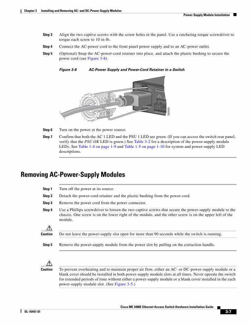
Step 5 (Optional) Snap the AC-power-cord retainer into place, and attach the plastic bushing to secure the power cord (see Figure 3-8).
Figure 3-8 AC-Power Supply and Power-Cord Retainer in a Switch
Step 6 Turn on the power at the power source.
Step 7 Confirm that both the AC 1 LED and the PSU 1 LED are green. (If you can access the switch rear panel, verify that the PSU OK LED is green.) See Table 3-2 for a description of the power-supply module LEDs. See Table 1-4 on page 1-9 and Table 1-5 on page 1-10 for system and power-supply LED descriptions.
Removing AC-Power-Supply Modules
Step 1 Turn off the power at its source.
Step 2 Detach the power-cord retainer and the plastic bushing from the power cord.
Step 3 Remove the power cord from the power connector.
Step 4 Use a Phillips screwdriver to loosen the two captive screws that secure the power-supply module to the chassis. One screw is on the lower right of the module, and the other screw is on the upper left of the module.
Caution Do not leave the power-supply slot open for more than 90 seconds while the switch is running.
Step 5 Remove the power-supply module from the power slot by pulling on the extraction handle.
Caution To prevent overheating and to maintain proper air flow, either an AC- or DC-power-supply module or a blank cover should be installed in both power-supply module slots at all times. Never operate the switch for extended periods of time without either a power-supply module or a blank cover installed in the each power-supply module slot. (See Figure 3-5.)
2808
28
3-7Cisco ME 3400E Ethernet Access Switch Hardware Installation Guide
OL-16447-01

Chapter 3 Installing and Removing AC- and DC-Power-Supply ModulesPower-Supply Module Installation
Installing a DC-Power-Supply ModuleThis procedure is for installing an DC-power-supply module into the PSU 1 power-supply slot. Repeat these steps to install a power-supply module in the PSU 2 power-supply slot.
To connect the switch to a DC-input power source, follow these steps:
1. Preparing for Installation, page 3-9
2. Grounding the Switch, page 3-9
3. Installing the DC-Power-Supply Module in the Switch, page 3-11
4. Wiring the DC-Input Power Source, page 3-12
Warning An exposed wire lead from a DC-input power source can conduct harmful levels of electricity. Be sure that no exposed portion of the DC-input power source wire extends from the terminal block plug. Statement 122
Warning Before connecting or disconnecting ground or power wires to the chassis, ensure that power is removed from the DC circuit. To ensure that all power is OFF, locate the circuit breaker on the panel board that services the DC circuit, switch the circuit breaker to the OFF position, and tape the switch handle of the circuit breaker in the OFF position. Use a voltmeter to test for 0 (zero) voltage at the power terminals on the chassis. Statement 196
Caution Installation of the equipment must comply with local and national electrical codes.
Note The grounding architecture of this product is DC-isolated (DC-I).
Note We recommend that you use 18 AWG copper wiring for Network Equipment Building Systems (NEBS) installation. This guideline follows the standard guidelines for DC-power wiring in the central office.
Note You can use the grounding lug to attach a wrist strap for ESD protection during servicing.
3-8Cisco ME 3400E Ethernet Access Switch Hardware Installation Guide
OL-16447-01

Chapter 3 Installing and Removing AC- and DC-Power-Supply ModulesPower-Supply Module Installation
Each DC-power input (A ± and B ±) is connected to both power-supply module 1 (PSU 1) and power-supply module 2 (PSU 2). The power-supply modules cannot be powered independently. DC inputs and returns are diode-isolated (Figure 3-9).
Figure 3-9 DC-Power-Supply Diagram
Preparing for Installation
Obtain these necessary tools and equipment:
• Ratcheting torque screwdriver with a number-2 and a number-1 Phillips head that exerts up to 15 inch-pounds (in-lb).
• Panduit crimping tool with optional controlled-cycle mechanism (model CT-720, CT-920, CT-920CH, CT-930, or CT-940CH).
• Wire-stripping tools.
• Copper ground wire (insulated or noninsulated) for the ground connection.
• Dual-hole, right-angle ground lug from the switch accessory kit (for the Cisco ME 3400E-24TS-M and the Cisco ME 3400EG-12CS-M).
• Dual-hole ground lug from the switch accessory kit (for the Cisco ME 3400EG-2CS-A).
• Four leads of 16-gauge copper wire.
• Four-position DC-terminal-block connector from the accessory kit.
To order a spare or replacement DC-connector, use this source:
• Amphenol PCD: ELFF0422S1 (Cisco part number 29-6063-0).
http://www.amphenolpcd.com/
Grounding the Switch
To make sure that the equipment is reliably connected to earth ground, follow the grounding procedure instructions and observe these warnings:
Warning This equipment must be grounded. Never defeat the ground conductor or operate the equipment in the absence of a suitably installed ground conductor. Contact the appropriate electrical inspection authority or an electrician if you are uncertain that suitable grounding is available. Statement 1024
Warning When installing or replacing the unit, the ground connection must always be made first and disconnected last. Statement 1046
DC ADC B
PSU-1
PSU-2
2809
36
3-9Cisco ME 3400E Ethernet Access Switch Hardware Installation Guide
OL-16447-01

Chapter 3 Installing and Removing AC- and DC-Power-Supply ModulesPower-Supply Module Installation
Caution To make sure that the equipment is reliably connected to earth ground, follow the grounding procedure instructions, and use a UL-listed lug suitable for number-6 AWG wire and two number-10-32 ground-lug screws.
Follow these steps to install either a single-ground lug or a dual-ground lug on the switch. Make sure to follow any grounding requirements at your site.
Step 1 Locate the ground adaptor and the dual-hole lug that ships with the switch.
Step 2 If your ground wire is insulated, use a wire stripping tool to strip the 12-gauge or 6-gauge ground wire to 0.5 inch (12.7 mm) ± 0.02 inch (0.5 mm) (Figure 3-10). Use 12-gauge copper ground wire for the single-ground connection. Use 6-gauge copper ground wire for the ground connection.
Figure 3-10 Stripping the Ground Wire
Step 3 Slide the open end of the ground lug over the exposed area of the wire.
Step 4 Use a Panduit crimping tool to crimp the ground lug to the wire (see Figure 3-11).
Figure 3-11 Crimping the Ground Lug
Step 5 Remove the ground screw from the switch rear panel.
Step 6 Attach the dual-hole lug and the wire assembly to the adaptor with the supplied nuts (Figure 3-12).
Step 7 Use a ratcheting torque screwdriver to torque the ground-lug screws to 60 in-lb.
Step 8 Connect the other end of the grounding wire to an appropriate grounding point at your site or to the rack.
InsulationWire lead
0.5 in. (12.7 mm) ± 0.02 in. (0.5 mm)
6052
8
2809
38
3-10Cisco ME 3400E Ethernet Access Switch Hardware Installation Guide
OL-16447-01

Chapter 3 Installing and Removing AC- and DC-Power-Supply ModulesPower-Supply Module Installation
Figure 3-12 Attaching the Ground Lug and Wire Assembly
Installing the DC-Power-Supply Module in the Switch
Step 1 Verify that power is off at the DC circuits. To ensure that power is removed from the DC circuits, locate the circuit breakers for the DC circuits, switch the circuit breakers to the OFF position, and tape the circuit-breaker switches in the OFF position.
Step 2 Insert the new power-supply module into the power-supply slot, and gently push it into the slot (see Figure 3-13). When correctly inserted, the power supply is flush with the switch rear panel.
Figure 3-13 Inserting a DC-Power-Supply Module
Step 3 Align the two captive screws with the screw holes. Use a ratcheting torque screwdriver to torque each screw to 7 in-lb.
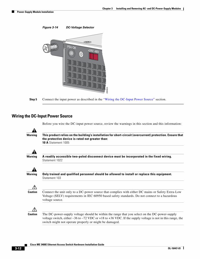
Step 4 Set the DC-voltage selector (see Figure 3-14):
• For telecom applications (–36 to –72 VDC), set the DC-voltage selector to –48 VDC.
• For industrial applications (+18 to +36 VDC), set the DC-voltage selector to +24 VDC.
1 Dual-hole ground lug
2809
39
1
PSU OK+24V -48V
DC
PSU OK+24V -48V
DC 2808
26
3-11Cisco ME 3400E Ethernet Access Switch Hardware Installation Guide
OL-16447-01
Chapter 3 Installing and Removing AC- and DC-Power-Supply ModulesPower-Supply Module Installation
Figure 3-14 DC-Voltage Selector
Step 5 Connect the input power as described in the “Wiring the DC-Input Power Source” section.
Wiring the DC-Input Power Source
Before you wire the DC-input power source, review the warnings in this section and this information:
Warning This product relies on the building’s installation for short-circuit (overcurrent) protection. Ensure that the protective device is rated not greater than: 10 A Statement 1005
Warning A readily accessible two-poled disconnect device must be incorporated in the fixed wiring. Statement 1022
Warning Only trained and qualified personnel should be allowed to install or replace this equipment. Statement 103
Caution Connect the unit only to a DC-power source that complies with either DC mains or Safety Extra-Low Voltage (SELV) requirements in IEC 60950 based safety standards. Do not connect to a hazardous voltage source.
Caution The DC-power-supply voltage should be within the range that you select on the DC-power-supply voltage switch, either –36 to –72 VDC or +18 to +36 VDC. If the supply voltage is not in this range, the switch might not operate properly or might be damaged.
PSU OK+24V -48V
2808
24
3-12Cisco ME 3400E Ethernet Access Switch Hardware Installation Guide
OL-16447-01

Chapter 3 Installing and Removing AC- and DC-Power-Supply ModulesPower-Supply Module Installation
Step 1 To ensure that all power is OFF, locate the circuit breaker on the panel board that services the DC circuit, switch the circuit breaker to the OFF position, and tape the switch handle of the circuit breaker in the OFF position.
Step 2 Locate the terminal block plug (see Figure 3-15).
Figure 3-15 Terminal Block Plug
Step 3 Identify the positive and negative feed positions for the terminal block connection. The wiring sequence is positive to positive and negative to negative for both the A and the B feed wires.
The switch front panel shows the positive and negative positions for both the A and B feed wires. (See Figure 3-16.)
Figure 3-16 Positive and Negative Positions
Step 4 Use an 18-gauge (1 mm) wire-stripping tool to strip each of the four wires coming from the DC-input power source to 0.27 inch (6.6 mm) ± 0.02 inch (0.5 mm). Do not strip more than 0.29 inch (7.4 mm) of insulation from the wire. Stripping more than the recommended amount of wire can leave exposed wire from the terminal block plug after installation.
Figure 3-17 Stripping the DC-Input Power Source Wire
Step 5 Insert the exposed wire of one of the four DC-input power source wires into the terminal block plug.
Make sure that you cannot see any wire lead. Only wire with insulation should extend from the terminal block.
2809
41
1 Positive position 2 Negative position
1
2809
42
2
0.25 in. (6.3 mm) ± 0.02 in. (0.5 mm)
6053
1
3-13Cisco ME 3400E Ethernet Access Switch Hardware Installation Guide
OL-16447-01

Chapter 3 Installing and Removing AC- and DC-Power-Supply ModulesPower-Supply Module Installation
Figure 3-18 Inserting Wires in the Terminal Block Plug
Step 6 Use a ratcheting torque screwdriver to torque the terminal block captive screw (above the installed wire lead) to 4.5 in-lb (see Figure 3-19).
Caution Do not overtorque the terminal-block captive screws. The recommended maximum torque is 4.5 in-lb.
Figure 3-19 Torquing the Terminal-Block Captive Screws
Step 7 Repeat Step 5 and Step 6 for the remaining three DC-input power source wires. Figure 3-20 shows the completed wiring of a terminal block plug.
1 Return (positive) Feed A 3 Return (positive) Feed B
2 Supply (negative) Feed A 4 Supply (negative) Feed B
2809
43
12
34
1 Torque to 4.5 in-lb
2809
441
3-14Cisco ME 3400E Ethernet Access Switch Hardware Installation Guide
OL-16447-01

Chapter 3 Installing and Removing AC- and DC-Power-Supply ModulesPower-Supply Module Installation
Figure 3-20 Completed Wiring of Terminal Block Plug for Telecom Applications
Step 8 Insert the terminal block plug in the terminal block header on the switch front panel. (See Figure 3-21).
Caution Secure the wires coming in from the terminal block so that they cannot be disturbed by casual contact. For example, use tie wraps to secure the wires to the rack.
Figure 3-21 Inserting the Terminal Block in the Block Header
Step 9 Secure the terminal block by using the screws on the far left and right of the terminal block.
Step 10 Remove the tape from the circuit-breaker switch handle, and move the circuit-breaker handle to the ON position.
Step 11 Move the DC-power source circuit-breaker handles to the ON position.
1 Return (positive) Feed A 3 Return (positive) Feed B
2 Supply (negative) Feed A 4 Supply (negative) Feed B
2809
45
12
34
2809
46
3-15Cisco ME 3400E Ethernet Access Switch Hardware Installation Guide
OL-16447-01

Chapter 3 Installing and Removing AC- and DC-Power-Supply ModulesPower-Supply Module Installation
Step 12 Confirm that both the DCA LED and the PSU 1 LEDs are green. (If you can access the switch rear panel, verify that the power-supply module PSU OK LED is green.) See Table 3-2 on page 3-4 for a description of the power-supply module LEDs. See Table 1-4 on page 1-9 and Table 1-6 on page 1-10 for the status and DC-power-supply LED descriptions.
Figure 3-22 shows the front of the switch when DC-power-supply modules are installed. The DC A and DC B LEDs are green when the respective feeds are active.
Figure 3-22 DC-Power Terminal Block With Two Feeds
Note This illustration shows two sets of feeds installed. You can install one set of feeds, A or B.
See the “Power Supply Settings” section on page 3-17 for information on how to configure the power supply settings.
Removing the DC-Power-Supply Module
Step 1 Turn off power at the DC circuits. To ensure that power is removed from the DC circuits, locate the circuit breakers for the DC circuits, switch the circuit breakers to the OFF position, and tape the circuit-breaker switches in the OFF position.
Step 2 Use a number-2 Phillips screwdriver to remove the plastic safety cover from the power-supply terminal blocks.
Step 3 Use a number-1 Phillips screwdriver to remove the DC-input power wires from the power terminals.
Step 4 Use a Phillips screwdriver to loosen the two captive screws at the lower edge that secure the power-supply module to the switch chassis.
Step 5 Remove the power-supply module from the power slot by pulling on the extraction handle.
Caution To prevent overheating and to maintain proper air flow, either a power-supply module or a blank cover must be installed in each power-supply module slot at all times.You can order the blank cover (part number ME34X-PWR-BLANK=) from Cisco.
2808
31
3-16Cisco ME 3400E Ethernet Access Switch Hardware Installation Guide
OL-16447-01

Chapter 3 Installing and Removing AC- and DC-Power-Supply ModulesPower Supply Settings
Power Supply Settings• Use the no power-supply global configuration command (the default) when installing one
power-supply module. The switch does not send an alarm when the second power-supply module is missing.
• Use the power-supply dual global configuration command when installing two power-supply modules. When both are operating properly, all applicable LEDs are green, and the switch does not send an alarm. If a power-supply module is missing, the switch sends an alarm. An error message appears and the appropriate power-supply LED turns red.
• Use the power-supply dual dc-feed global configuration command when two DC-input feeds are connected to the DC-power source. When both are operating properly, all the applicable LEDs are green and the switch does not send an alarm. If only one DC-input feed is connected, and there is at least one DC-power-supply module installed, the switch sends an alarm. An error message appears and the DC-power-supply LED for the missing DC-input feed turns amber. The LED for the connected DC-input feed turns green.
• Use the no power-supply dual dc-feed global configuration command when only one DC-input feed is connected. The switch does not send an alarm when the second DC-input feed is not connected.
See the switch software configuration guide and switch command reference for more details on these settings.
3-17Cisco ME 3400E Ethernet Access Switch Hardware Installation Guide
OL-16447-01

Chapter 3 Installing and Removing AC- and DC-Power-Supply ModulesPower Supply Settings
3-18Cisco ME 3400E Ethernet Access Switch Hardware Installation Guide
OL-16447-01


![[MEAN WELL] 1982 (Charger) DC/AC (Inverter) 8000 (DoE ... · PDF fileAC/DC DC/DC (Converter) (Adaptor) (Charger) DC/AC (Inverter) 8000 LED ... AC AC AC GE12/18/24/30 I AC AC Plug-AU](https://img.pdfslide.net/doc/110x75/5a73363b7f8b9abb538e72a6/mean-well-1982-charger-dcac-inverter-8000-doe-a-acdc-dcdc-converter.jpg)