Embed Size (px)
Citation preview
Installing, Operating & MaintainingMUNCHKIN HIGH EFFICIENCY HEATER
I z_ WARNING:If the information in this manual is not followed exactly, a fire or explosion may result
causing property damage, personal injury or loss of life.
Do not store or use gasoline or other flammable vapors and liquids
in the vicinity of this or any other appliance.WHAT TO DO IF YOU SMELL GAS
• Do not try to light any appliance.• Do not touch any electrical switch: do not use any phone in
your building.• Immediately call your gas supplier from a neighbor's phone.
Follow the gas supplier's instructions.• If you cannot reach your gas supplier, call the fire department.
Installation and service must be performed by a qualifiedinstaller, service agency or the gas supplier.
CONTROLS
C US
_WARNING:
This manual must only be used by a qualified heating installer / service technician. Failure
to comply could result in severe personal injury, death or substantial property damage. It is
also important to keep these Instructions with the appliance.
HEAT TRANSFER PRODUCTS, INC.
120 BRALEY RD., E. FREETOWN, MA 02717
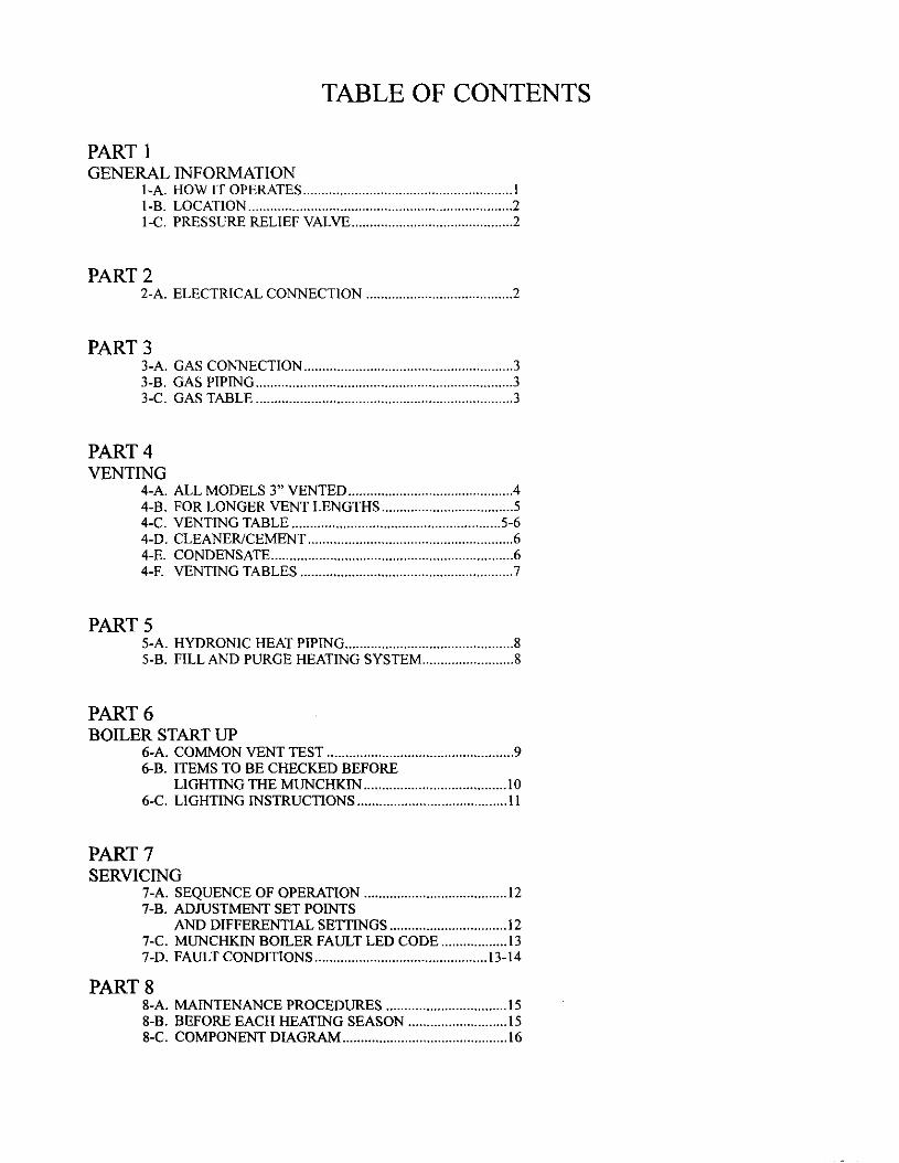
TABLE OF CONTENTS
PART 1GENERAL INFORMATION
1-A. HOW IT OPERATES ......................................................... Il-B. LOCATION ........................................................................ 21-C. PRESSURE RELIEF VALVE ............................................ 2
PART 22-A. ELECTRICAL CONNECTION ........................................ 2
PART 33-A. GAS CONNECTION ......................................................... 33-B. GAS PIPING ...................................................................... 33-C. GAS TABLE ...................................................................... 3
PART 4VENTING
4-A. ALL MODELS 3" VENTED ............................................. 44-B. FOR LONGER VENT LENGTHS .................................... 54-C. VENTING TABLE ......................................................... 5-64-D. CLEANER/CEMENT ........................................................ 64-E. CONDENSATE .................................................................. 64-F. VENTING TABLES .......................................................... 7
PART 55-A. HYDRONIC HEAT PIPING .............................................. 85-B. FILL AND PURGE HEATING SYSTEM ......................... 8
PART 6BOILER START LIP
6-A. COMMON VENT TEST ................................................... 96-B. ITEMS TO BE CHECKED BEFORE
LIGHTING THE MUNCHKIN ....................................... 106-C. LIGHTING INSTRUCTIONS ......................................... 11
PART 7SERVICING
7-A. SEQUENCE OF OPERATION ....................................... 127-B. ADJUSTMENT SET POINTS
AND DIFFERENTIAL SETTINGS ................................ 127-C. MUNCHKIN BOILER FAULT LED CODE .................. 137-D. FAULT CONDITIONS ............................................... 13-14
PART 88-A. MAINTENANCE PROCEDURES ................................. 158-B. BEFORE EACH HEATING SEASON ........................... 158-C. COMPONENT DIAGRAM ............................................. 16
I WARNINGS CAUTIONS
THIS UNIT IS FOR CATEGORY IV VENTING - 2 PIPE ONLY. THIS IS A SEALED
COMBUSTION APPLIANCE,
THIS HEATER INSTALLATION MUST CONFORM TO THE LATEST EDITION OF THE
"NATIONAL FUEL GAS CODE" ANSI Z223.1 STATE AND LOCAL CODES MIGHT ALSO
APPLY TO INSTALLATION.
• WHERE REQUIRED BY THE AUTHORITY HAVING JURISDICTION, THE INSTALLATION
MUST CONFORM TO THE STANDARDS FOR CONTROLS AND SAFETY DEVICES FOR
AUTOMATICALLY FIRED BOILERS, ANSI/ASME BOILER AND PRESSURE VESSEL
CODE, Section IV.
• THE HEATER, GAS PIPING, WATER PIPING, VENTING AND ELECTRICAL MUST BE
INSTALLED BY TRAINED & QUALIFIED PERSONNEL FAMILIAR WITH INSTALLATION
PRACTICES AND LOCAL CODE AND LICENSING REQUIREMENTS.
• IF THE INFORMATION IN THESE INSTRUCTIONS ARE NOT FOLLOWED EXACTLY, A
FIRE OR EXPLOSION MAY RESULT; CAUSING PROPERTY DAMAGE, PERSONAL
INJURY, OR DEATH.
• DO NOT STORE OR USE GASOLINE OR OTHER FLAMMABLE VAPORS AND LIQUIDS IN
THE VICINITY OF THIS OR ANY OTHER APPLIANCE;
WHAT TO DO IF YOU SMELL GAS:
Do not try to light any appliance:Do not touch any electrical switch: do not use any phone in your building:Immediately call your gas supplier from a neighbors' phone:Follow the gas suppliers' instructions"If you cannot reach your gas supplier, call the fire department:Installation and service must be performed by a qualified installer: service agency or the gas supplier.
PART 1
GENERAL INFORMATION1-A. HOW IT OPERATES
When the room thermostat calls for heat, the Munchkin control board will start the pump and start to monitor the returntemperature of the system before the heater will begin to heat the water. Once the controller has sensed a drop in the returnwater temperature below the temperature set point minus the differential set point, the boiler will start to heat the water. Thiseliminates the Munchkin starting every time the thermostat calls for heat. This feature keeps the system from short cycling.
Once the system has sensed the temperature difference, the Mnnchkin will activate the blower motor for 5 seconds to prepurgethe system before starting the Munchkin. The Munchkin controller will now start to modulate the pre-mix burner based onanalyzing the turn temperature, supply water temperature, and the set point temperature. By compiling this information, thecontroller utilizes an algorithm to fully adjust the firing rate while maintaining the desired output temperature. The pre-mixburner fans have a low-voltage direct current drive motor with a pulse relay counting. This system allows precise control overthe fan speed and combustion air volumes. Coupled with the Honeywell gas valve and the Venturi system set to provide aone-to-one ratio of precisely measured volumes of fuel to air, accurate and instant burner output is achieved. This keeps theMunchkin running at the highest elTleiency.
When the thermostat is satisfied, the Munchkin will then go through a 4 second post-purge cycle before shutting off. EveryMunchkin heater is equipped with an indicator light which will pulse constantly in normal operation. When a problem occurs,the indicator light will blink slowly to indicate the heater fault.
I-B. LOCATION
_WARNING:MUNCHKIN MUST BE SET ON A LEVEL SURFACE SO
CONDENSATION DOES NOT BACK UP INSIDE BOILER.*
The Munchkin is designed for Installation on combustible flooring, in alcoves, basements, closets, utility rooms. TheMnnchkin shall be installed so that the gas ignition system components are protected from water. This includes all relatedpiping and components.Choose a location for your Munchkin, centralized to the piping system, along with consideration to vent pipe length. As thelength of vent pipe increases the firing rate of the Munchkin decreases. You must also locate the Munchkin where it will notbe exposed to freezing temperatures. Additionally, you will need to place the heater so that the controls, inletJoutlet, and gasvalve are easily accessed. This Munchkin must not be installed outdoors, as it is certified as an indoor appliance, and must bekept vertical and on a level surface. Also, care must be exercised when choosing the location of this appliance; where leakagefrom the relief valve, from related piping will not result in damage to the surrounding areas or to the lower floors of thebuilding. A heater should always be located in a area with a floor drain or installed in a suitable drain pan. Properclearance must be provided around the Munchkin as follows: Sides, bottom, top, and back are 0" (zero clearance). Venting isalso zero clearance. Front of the appliance needs 4" service clearance minimum. This front service may be achieved by a non-rated or combustible door or access panel; providing the 4" front, 15" on top, and 16" either side service clearance is achievedwhen the front cover is removed. Under no circumstances, shall Heat Transfer Products Inc. be held liable for any suchwater damage whatsoever. This heater must not be located near flammable liquids such as gasoline, adhesives,solvents, paint thinners, butane, liquefied propane, etc.; as the controls of this appliance could ignite those vapors,causing an explosion.
1-C. PRESSURE RELIEF VALVE
A pressure relief valve is installed into the front right side manifold we recommend a WATTS ¾"M 335 MI valve orequivalent and meets the requirements of ANSI/ASME Section IV for heating boilers. A 3A"pipe must be directed to a floordrain or suitable location within 6" of drain or floor. Protect from freezing, do not plug or cap pressure relief valve. Seriousexplosion causing property damage and or loss of life could result. Under no circumstances should the relief valve beeliminated, capped or plugged.
SERVICING - _ WARNING - CAUTION
Before servicing let the munchkin cool down! Shut off electrical and gas supply.Failure to follow warning could result in severe burn, electrical shock, gas
leakage, fire or explosion.
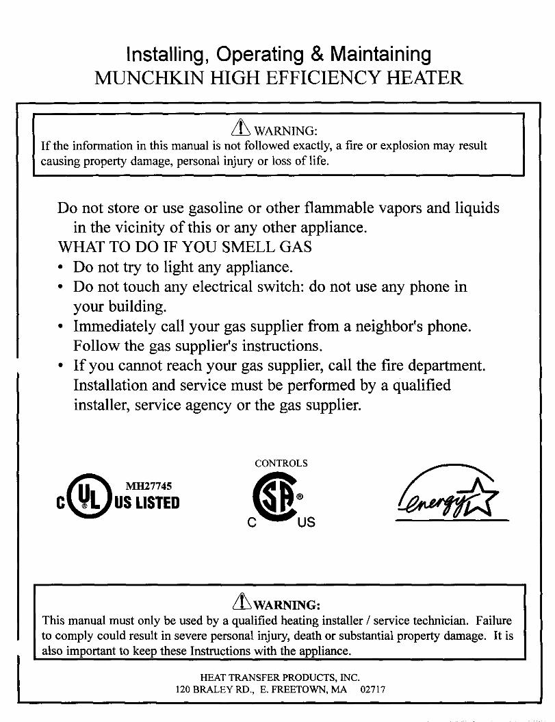
PART 22-A. ELECTRICAL CONNECTION
The electrical connection for the Munchkin is on the left side of the unit. There is a t½,,knockout location for electrical
connection. All electrical wiring must be performed by a qualified licensed electrician, and in accordance with NationalElectrical Code, or to the applicable local codes and standards. For your convenience we have labeled all the wire which needsto be connected to operate the Munckin. Caution: Do not remove labels on wires prior to disconnection. The electricalrequirements are for standard 120 volts, 60 Hz 10 amp service. This unit must be wired with #14 awg, and fused for no morethan 15 amps. It is of extreme imnortance that this unit be nronerlv _rounded! There are two ground points in theelectrical compartment that must be connected to the building ground system. Connect the building to the green ground screwand the green ground wire. It is very imnortant that the buildin_ system around is insnected by a uualified electrician.prior to makin_ this connection.The black wire is the hot lead and white wire is the neutral lead. Once all connections have been made the electricalaccess may be closed. It is very imnortant that the electrical nower is not turned on at this time! A green LED isprovided on the main control board. This LED must be illuminated when the Mnnchkin is turned on for properoperation.
2
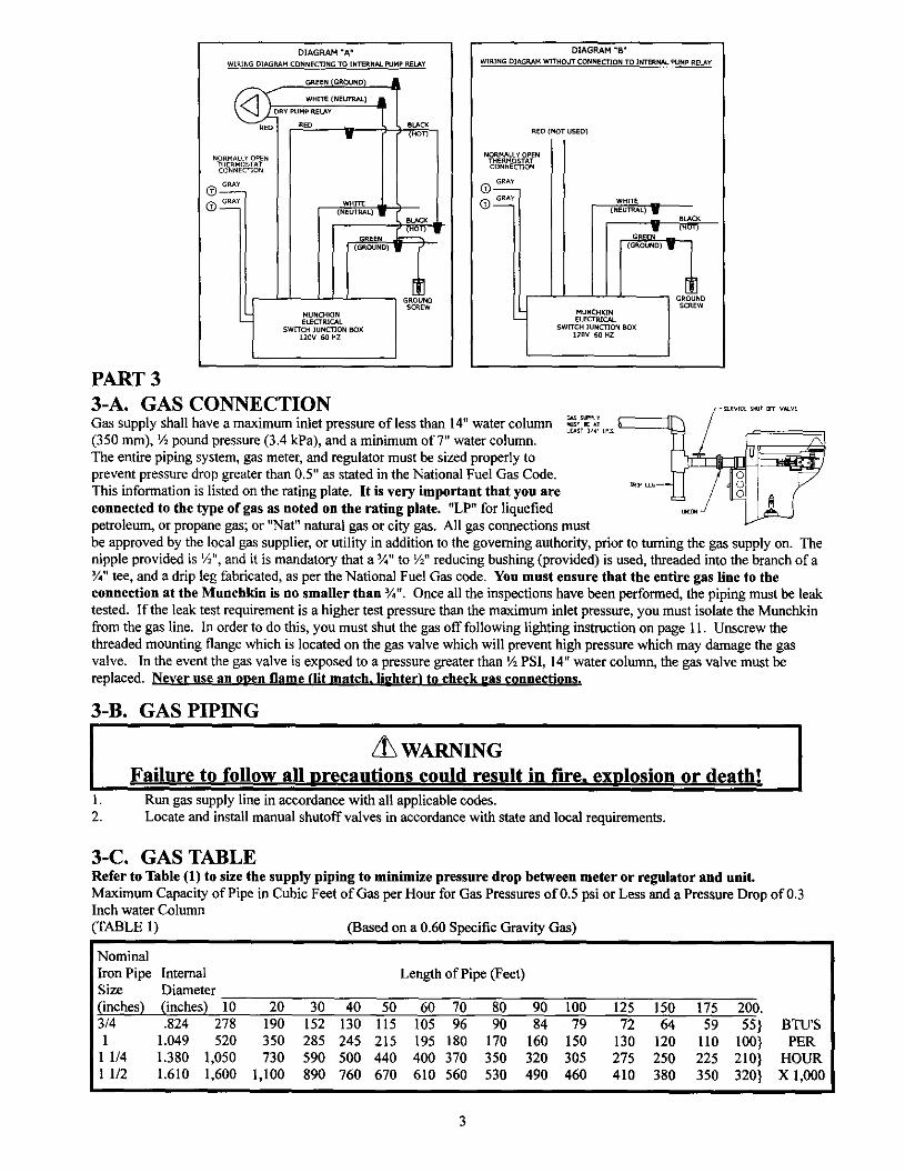
DIAGRAM "A"
WIRINGOJAGP,AMCONNEC'FINGTO INI_RNAL_Lr;4p RELAy
GROUNDSCREW
DIAGRAM "B"
WIRING DIAGIr_f4WITHOUTCONN_CllON TO INTERN_,.FUNpRELAy
RED (NOT USED)
NORMALLY OPENTH_RM STATCONNeCtiON
GRAY
WH_
BLACK
W (HOT)
GROUNDSCREW
MUN_KINELECTRICAL
SWITCH 3U NCTJON BOX12QV 6O HZ
PART 3
3-A. GAS CONNECTIONGas supply shall have a maximum inlet pressure of less than 14"water column(350 ram), ½ pound pressure (3.4 kPa), and a minimum ofT' water column.The entire piping system, gas meter, and regulator must be sized properly toprevent pressure drop greater than 0.5" as stated in the National Fuel Gas Code.This information is listed on the rating plate. It is very important that yon areconnected to the type of gas as noted on the rating plate. "LP" for liquefied
_RVlCE S_ll_ CCr V_-VE
Mt_T lie _1LUST _/_' Lp_
_Ep t_
petroleum, or propane gas; or "Nat" natural gas or city gas. All gas connections mustbe approved by the local gas supplier, or utility in addition to the governing authority, prior to turning the gas supply on. Thenipple provided is ½", and it is mandatory that a %" to ½" reducing bushing (provided) is used, threaded into the branch of a%" tee, and a drip leg fabricated, as per the National Fuel Gas code. You must ensure that the entire gas line to theconnection at the Munchkin is no smaller than 3/4". Once all the inspections have been performed, the piping must be leaktested. Iftbe leak test requirement is a higher test pressure than the maximum inlet pressure, you must isolate the Munchkinfrom the gas line. In order to do this, you must shut the gas off following lighting instruction on page 11. Unscrew thethreaded mounting flange which is located on the gas valve which will prevent high pressure which may damage the gasvalve. In the event the gas valve is exposed to a pressure greater than ½ PSI, 14" water column, the gas valve must bereplaced. Never use an onen flame (lit match, li_hterI to check _as connections.
3-B. GAS PIPING
1.
2.
WARNING
Failure to follow all nrecautions could result in fire. explosion or death!Run gas supply line in accordance with all applicable codes.Locate and install manual shutoff valves in accordance with state and local requirements.
3-C, GAS TABLERefer to Table (1) to size the supply piping to minimize pressure drop between meter or regulator and unit.Maximum Capacity of Pipe in Cubic Feet of Gas per Hour for Gas Pressures of 0.5 psi or Less and a Pressure Drop of 0.3Inch water Column
(TABLE 1) (Based on a 0.60 Specific Gravity Gas)
Nominal
Iron Pipe Internal Length of Pipe (Feet)Size Diameter
(inches) (inches) 10 20 30 40 50 60 70 80 90 100 125 150 175 200.3/4 .824 278 190 152 130 115 105 96 90 84 79 72 64 59 55} BTU'S1 1.049 520 350 285 245 215 195 180 170 160 150 130 120 110 100} PER
1 1/4 1.380 1,050 730 590 500 440 400 370 350 320 305 275 250 225 210} HOUR1 1/2 L610 1,600 1,100 890 760 670 610 560 530 490 460 410 380 350 320} X1,000
It isrecommendedthatasoapysolutionbeusedtodetectleaks.Bubbleswillappearonpipetoindicatealeakispresent.Thegaspipingmustbesizedfortheproperflowandlengthofpipe,toavoidpressuredrop.Boththegasmeterandthegasregulatormustbeproperlysizedforthetotalgasload.If youexperienceapressuredropgreaterthan1"WC,themeterorregulatororgaslineisundersizedorinneedofservice.Youcanattachametertotheincominggasdripleg,byremovingthecapandinstallingthemeter.The gas pressure must remain between 7" and 14" during stand-by and unit running heat cycle.If an in-line regulator is used, it must be a minimum of 10 feet from the Manchkin. It is very important that the gas line isproperly purged by the gas supplier or utility. Failure to properly purge the lines or improper line sizing, will result inthe failure of the Munehkin lighting off. This problem is especially noticeable in NEW LP installations, and also in emptytank situations. This can also occur when a utility company shuts off service to an area to provide maintenance to their lines.This valve must not be replaced with a conventional valve under any circumstances. As an additional safety feature, thisvalve has a flanged connection to the Venturi and blower.
PART 4
VENTING4-A. ALL MODELS 3" VENTED
WARNING!!
[t is extremely important to follow these venting instructions exactly. Failure tofollow the venting instructions can cause severe personal injury, death or
substantial property damage.
The inlet pipe on the back of the cabinet, use 3" PVC schedule 40. It is very important that you plan the location properly, toeliminate long pipe runs and excessive fittings. Inlet pipe size must not be reduced. Do not combine the inlet air with anyother inlet pipe including an inlet to an additional similar appliance. The joints must be properly cleaned, primed, andcemented. The piping must also be properly supported as per Local and National Standard Plumbing Codes. It is importantthat the piping must be clean and free from burs, debris, ragged ends, and particles of PVC.
Exhaust pipe on the back of the cabinet will use 3" PVC Schedule 40. For concrete construction or to meet certain fire codes,exhaust piping inlet air pipe must be 3" CPVC Schedule 40 or 80, (only to meet local fire codes). The balance of the inlet andexhaust piping may be PVC Schedule 40 or 80, orABS solid only, NOT FOAM CORE.
The only approved exhaust vent materials are PVC Schedule 40 (NOT FOAM CORE PIPE!). Exhaust piping should besloped back to the connection on the Munchkin, at least %" per foot to remove additional condensate that forms within thepipe. The total combined length of pipe (intake piping plus exhaust piping added together) including elbow allowances intakeand exhaust (each elbow = 5' of pipe) should not exceed 85'. The combined vent length should not be less than a combinedlength of 6' plus two 90 degree elbows. Choose your vent termination locations carefully. You must additionally make certainthat exhaust gas does not re-circulate back into the intake pipe. You must place them in an open area, and follow thefollowing guidelines.
1)
2)3)4)5)6)7)8)9)
10)
il)
Never vent into a walkway, patio area, alley or otherwise public area less than 7' fromthe ground;Never vent over / under a window or over a doorway;Never install a heat saver or similar product to capture waste heat from exhaust;Always have vent location at least 1' above maximum snow level;Always have vent 1' above ground level, away from shrubs and bushes;Follow local gas codes in your region or refer to National Fuel Gas Code, Can B149;Always have vent at least 3' from an inside comer of outside walls;Maintain at least 4' clearance to electric, gas meters, and exhaust fans or inlets;Very lmoortant! Inlet air must be taken from outside of building, next to exhaustoutlet, no closer than 8";Always place screens in all openings in intake and exhaust to prevent foreign matterfrom entering the Munchkin.The vent intake and exhaust must be properly cleaned and glued, for pressure tight joint. Several methodsfor venting the Mtmchkin can be found in Figures 1 thru 6. Use the following layout as a guideline; certainsite conditions such as multiple rooflines/pitcbes may require venting modifications-cnnsult factory. Theair inlet must be a minimum of 1' vertically above the maximum snow level or 24" which ever is greater.The air inlet must also be a minimum of 10' horizontally from the roof, and terminated with a tee. Theexhaust must be a minimum of 24" above the air inlet opening, and terminated with a coupling. It is veryimportant that there are no other vents, chimneys, or air inlets in any direction for at least 4'. All
4
12)
venting must be properly supported, as the Munchkin is not intended to support any ventingwhatsoever. All piping, glue, solvents, cleaners, fittings, and components, must conform to ASTM(American Society for Testing and Materials), andANSI (American National StandardInstitute).It is recommended that you use one of the optional vent kits specifically for Munchkininstallations.(KGAVT0601CVT (3 in.) or V 1000). NOTE: WHEN USING THE HGAVTT601CVT KIT,REMOVE THE 2 SCREENS FROM THE PROVIDED INLET TEE, AND INSTALL THEM IN THEINLET SOCKET AND OUTLET SOCKET OF THE KIT PRIOR TO INSTALLING THE SCHEDULE40 PIPE AND GLUING
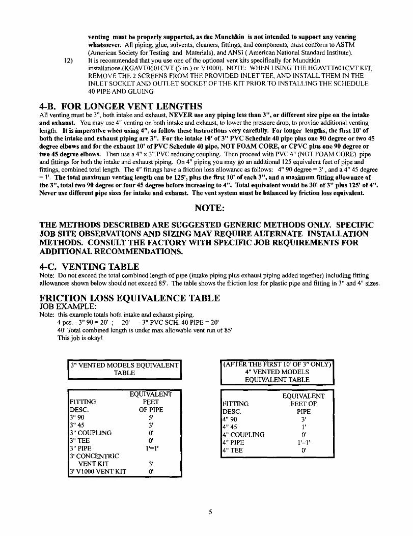
4-B. FOR LONGER VENT LENGTHSAll venting must be 3", both intake and exhaust, NEVER use any piping less than 3", or different size pipe on the intakeand exhaust. You may use 4" venting on both intake and exhaust, to lower the pressure drop, to provide additional ventinglength. It is imperative when using 4", to follow these instructions very carefully. For longer lengths, the first 10' ofboth the intake and exhaust piping are 3". For the intake 10' of 3" PVC Schedule 40 pipe plus one 90 degree or two 45degree elbows and for the exhaust 10' of PVC Schedule 40 pipe, NOT FOAM CORE, or CPVC plus one 90 degree ortwo 45 degree elbows. Then use a 4" x 3" PVC reducing coupling. Then proceed with PVC 4" (NOT FOAM CORE) pipeand fittings for both the intake and exhaust piping. On 4" piping you may go an additional 125 equivalent feet of pipe andfittings, combined total length. The 4" fittings have a friction loss allowance as follows: 4" 90 degree = 3', and a 4" 45 degree= 1'. The total maximum venting length can be 125', plus the first 10' of each 3", and a maximum fitting allowance ofthe 3", total two 90 degree or four 45 degree before increasing to 4". Total equivalent would be 30' of 3" plus 125' of 4".Never use different pipe sizes for intake and exhaust. The vent system must be balanced by friction loss equivalent.
NOTE:
THE METHODS DESCRIBED ARE SUGGESTED GENERIC METHODS ONLY. SPECIFIC
JOB SITE OBSERVATIONS AND SIZING MAY REQUIRE ALTERNATE INSTALLATION
METHODS. CONSULT THE FACTORY WITH SPECIFIC JOB REQUIREMENTS FORADDITIONAL RECOMMENDATIONS.
4-C. VENTING TABLENote: Do not exceed the total combined length of pipe (intake piping plus exhaust piping added together) including fittingallowances shown below should not exceed 85'. The table shows the friction loss for plastic pipe and fitting in 3" and 4" sizes.
FRICTION LOSS EQUIVALENCE TABLEJOB EXAMPLE:Note: this example totals both intake and exhaust piping.
4pcs.-3"90=20' ; 20' -3"PVCSCH. 40PIPE=20'40' Total combined length is under max allowable vent run of 85'This job is okay!
3" VENTED MODELS EQUIVALENT ITABLE [
EQUIVALENTFITTING FEETDESC. OF PIPE3" 90 5'3" 45 3'3" COUPLING 0'3" TEE 0'3" PIPE 1'=1'3' CONCENTRIC
VENT KIT 3'3' V1000 VENT KIT 0'
(AFTER THE FIRST 10' OF 3" ONLY) ]4" VENTED MODELS I
EQUIVALENT TABLE ]
EQUIVALENTFITTING FEET OFDESC. PIPE
4" 90 3'4" 45 1'
4" COUPLING 0'4" PIPE 1'=1 '
4" TEE 0'
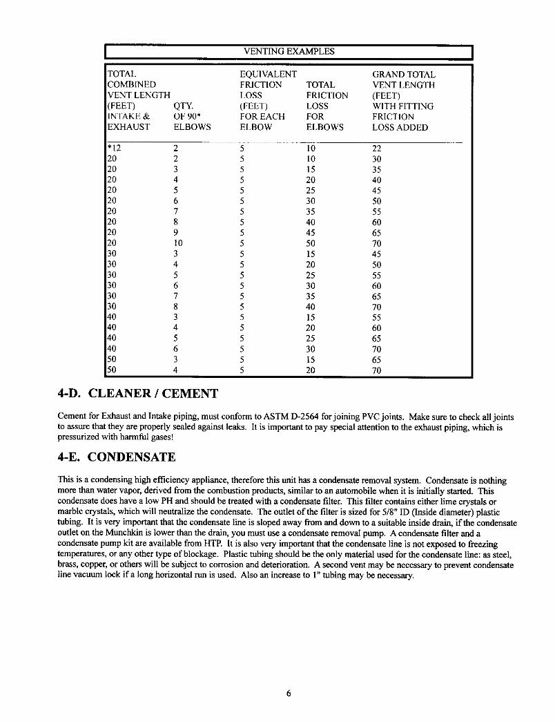
VENTINGEXAMPLES
TOTAL EQUIVALENTCOMBINED FRICTION TOTALVENTLENGTH LOSS FRICTION/FEET) QTY. (FEET) LOSSINTAKE& OF90* FOREACH FOREXHAUST ELBOWS ELBOW ELBOWS
GRANDTOTALVENTLENGTH(FEET)WITHFITTINGFRICTIONLOSSADDED
'12 2 5 10 2220 2 5 10 3020 3 5 15 3520 4 5 20 4020 5 5 25 4520 6 5 30 5020 7 5 35 5520 8 5 40 6020 9 5 45 6520 10 5 50 7030 3 5 15 4530 4 5 20 5030 5 5 25 5530 6 5 30 6030 7 5 35 6530 8 5 40 7040 3 5 15 55_0 4 5 20 60_0 5 5 25 65_0 6 5 30 7050 3 5 15 6550 4 5 20 70
4-D. CLEANER / CEMENT
Cement for Exhaust and Intake piping, must conform to ASTM D-2564 for joining PVC joints. Make sure to check all jointsto assure that they are properly sealed against leaks. It is important to pay special attention to the exhaust piping, which ispressurized with harmful gases!
4-E. CONDENSATE
This is a condensing high efficiency appliance, therefore this trait has a condensate removal system. Condensate is nothingmore than water vapor, derived from the combustion products, similar to an automobile when it is initially started. Thiscondensate does have a low PH and should be treated with a condensate filter. This filter contains either lime crystals ormarble crystals, which will neutralize the condensate. The outlet of the filter is sized for 5/8" ID (Inside diameter) plastictubing. It is very important that the condensate line is sloped away from and down to a suitable inside drain, if the condensateoutlet on the Munchkin is lower than the drain, you must use a condensate removal pump. A condensate filter and acondensate pump kit are available from HTP. It is also very important that the condensate line is not exposed to freezingtemperatures, or any other type of blockage. Plastic tubing should be the only material used for the condensate line: as steel,brass, copper, or others will be subject to corrosion and deterioration. A second vent may be necessary to prevent condensateline vacuum lock ifa long horizontal rtm is used. Also an increase to 1" tubing may be necessary.

VENTING DIAGRAMS 4-E
MUtiC_(IN BOILER
3" SIDEVALL VENT _41TH TEE (INTAKE) I, COUPLING (EXHAUST)
FIGURE 1
mmIMPDRTANTNDTEI ALL VENT PIPES MUST BE GLUED, PRQFtZRLYSUPPQRTED, ANI) THE EXHAUST MU_T BE PITCH£I} A MINIMUM DF
A 1/4" PER F{]DT BACK TO THE Bf]ILER (T{] ALLDV DRAINAGE DF EDNI)EN_ATE)mm
WALL
-%W_KH I_
INT_ aoamm] m_ W I_a_
3" SIDEVALL VENT VITH TEE (INTAKE) & CDIJPI_ING (EXHAUST)
gIGtJRZ 2m,IMPORTANT NOTE] ALL VENT PIPES MUST BE GLLICD, PRDPERLY
SUPPDRTED, ANI) THE EXHAUST MUST BE PITCHE]3 A MINIU OFA 1/4" PER FDQT BACK TO THE BDIL[R (T(] ALL[_ ,t _AINAC_E QF CDN]!]EK_'-_TE)mm
WALL
_C:,fKI_ ECtLER
vIooowJ_r Kff
--1rm _q_ o_
J
3° $11)EVALL VENT VITH V1000 KIT
FIGLIR£ 3uuINPDRTANT NQTE, ALL VENT PIPES MUST BE GLUED, PROPERLY
SUPPDRTES. AND THE EXHAUST MUST BE PITCHED A MINIMUM OFA 1/4" PER FODT BACK TD THE SDILER (TQ ALLDV DRAINAGE DF EDNgENSATE)um
s'n_ cmmu_
k,u4cm_ w
3" _ VI_NT VITH TIE[ (It4TAKI_) L C01_'_t.IM_ (I_T)
rlr.dJ_[ 4
.uINFI_T_T WOT£, _ Vf:WT I_$ 14U_T K 6LtE_ I_¥SUPP(]_Tgg, _ THE CXN_U_T HU_T K pITC;4ED A )_NINUN OF
A _/4" p_R rOOT _ TO TH[ IO_.£R (T0 _d-LOW" _ (Ire 1:_4]W:N_TIE)UE
W_LL
t, m
wE_w
3" SII_VALL VENT VITH 3° CDNCENTRIE VENT KIT (KGAVTO6OtCVT)
FIGURE 5.mIMPQRTANT NOTE. ALL VENT PIPES MUST BE GLUEg, PRDP_NLY
SUPPORTEg, aN9 THE EXHAUgT MUST BE PITCHED /_NININUN DrA I/4" PER FDDT BACK TD TI_ _QILER (TD ALLI]V SNAINAGE OF EDNgEN$_TE..u
7
3 ° _ VENT VITIt 3_ CI]_ENTRIC VENT KIT (KGAVT0_01CVT)
gIC_JRE6mlIDtFI]RT/elT ND't£. N.L VENT PIPITS 14i_T II_ C.LtJ_J, PR[Ia_RLY
SUPPORTED, N_ PITCHES /_ NININUN OF" /_ _J_RTER INCH _ rOOTII_CK TO THE E_ILER (Tfl /_LL0V _R_I_ OF- CON_NSAT[_m
PART 55-A. HYDRONIC HEAT PIPING
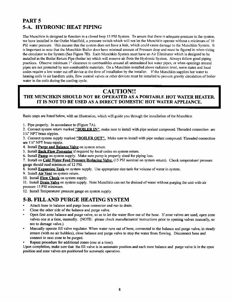
The Munchkin is designed to function in a closed loop 15 PSI System. To assure that there is adequate pressure in the system,we have installed in the Outlet Manifold, a pressure switch which will not let the Mnnchkin operate without a minimum of 10PSI water pressure. This assures that the system does not have a leak, which could cause damage to the Munchkin System. Itis Important to note that the Munchkin Boiler does have minimal amount of Pressure drop and must be figured in when sizingthe circulator to the System (See Figure 7B). Each Munchkin System must have an Air Eliminator which is designed to beinstalled in the Boiler Return Pipe (boiler in) which will remove air from the Hydronic System. Always follow good pipingpractices. Observe minimum 1" clearance to combustibles around all uninsulated hot water pipes, or when openings aroundpipes are not protected by non-combustible materials. On a Munchkin installed above radiation level, some states and localcodes require a low water cut off device at the time of installation by the installer. If the Manchkin supplies hot water toheating coils in air handlers units, flow control valves or other devices must be installed to prevent gravity circulation of boilerwater in the coils during the cooling cycle.
CAUTION! !THE MUNCHKIN SHOULD NOT BE OPERATED AS A PORTABLE HOT WATER HEATER.
IT IS NOT TO BE USED AS A DIRECT DOMESTIC HOT WATER APPLIANCE.
Basic steps are listed below, with an Illustration, which will guide you through the installation of the Munchkin
1. Pipe properly. In accordance to (Figure 7A).2. Connect system return marked "BOILER IN". make sure to install with pipe sealant compound. Threaded connection are1¼" NPT brass nipples.3. Connect system supply marked "BOILER OUT". Make sure to install with pipe sealant compound. Threaded connectionare 1¼" NPT brass nipple.4. Install Pur_e and Balance Valve on system return.5. Install Back Flow Preventer if required by local codes on system return.6. Install Pumo on system supply. Make sure pump is properly sized for piping loss.7. Install on Cold Water Feed Pressure Reduein_ Valve. (15 PSI nominal on system return). Check temperature/pressuregauge should read minimum of 12 PSI.8. Install Exnansion Tank on system supply. Use appropriate size tank for volume of water in system.9. Install Air Vent on system return.10. Install _ on system supply.11. Install _ on system supply. Note Mnnchkin can not be drained of water without purging the unit with airpressure 15 PSI minimum.12. Install Temperature/pressure gauge on system supply.
5-B. FILL AND PURGE HEATING SYSTEMAttach hose to balance and purge hose connector and run to drain.Close the other side of the balance and purge valve.
Open first zone balance and purge valve, so as to let the water flow out of the hose. If zone valves are used, open zonevalves one at a time, manually. (NOTE: please check manufacturers' instructions prior to opening valves manually, sonot to damage valve.)
Manually operate fill valve regulator. When water runs out of hose, connected to the balance and purge valve, in steadystream (with no air bubbles), close balance and purge valve to stop the water from flowing. Disconnect hose andconnect to next zone to be purged.Repeat procedure for additional zones (one at a time).
Upon completion, make sure that the fill valve is in automatic position and each zone balance and purge valve is in the openposition and zone valves are positioned for automatic operation.
I
NOTE: Installation that incorporate Standing Iron Radiation and systems manual vents high points. Follow the aboveprocedure than slatting with nearest manual air vent, open vent until water flows out; close vent. Repeat procedure, workingyour way toward furthest air vent. It may be necessary to install basket strainer in older hydronic system where largeramounts of sediment may be present. Annual cleaning of the strainer may be necessary.
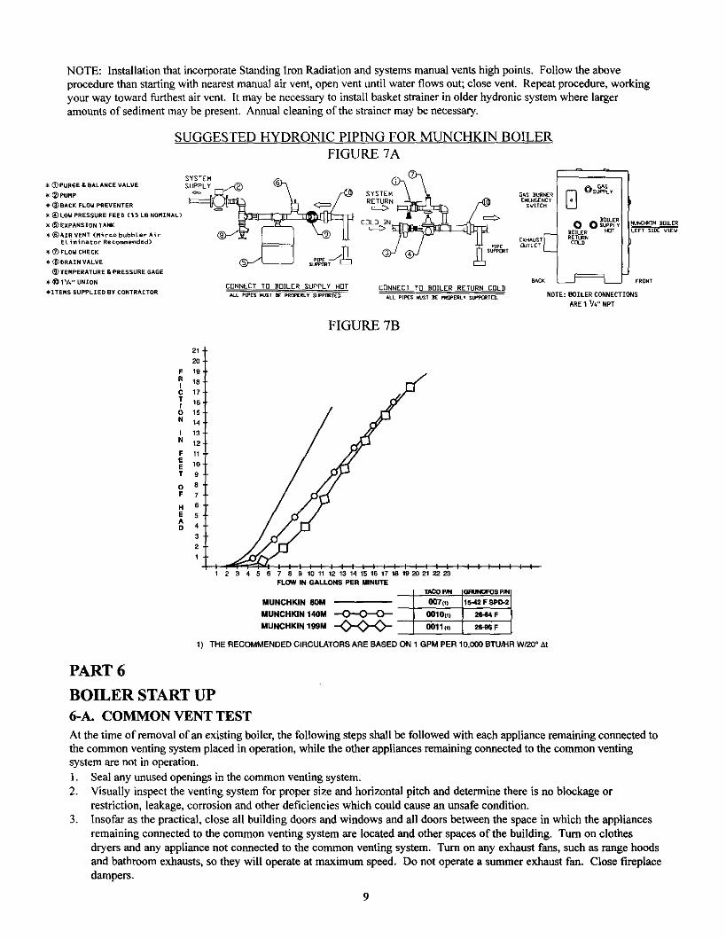
SUGGESTED HYDRON1C PIPING FOR MUNCHK1N BOILER
FIGURE 7A
SYSTEM_ --__um{_PURGE & BALANCE VALVE S_LY_
SYSTEM
EMERGCNCy_ _ PUMP R--N G_S 9URN[_
_ I_BACK FLOW pREVENTER _ _ SV[TCH
:_ _)LOW PRESSURE FEED (15 LB NOMINAL)
_ _ EXPANSION TANK C0kD_ IN
_ _AIR VENT (Mir co bubbler Air EXHAUST_El iminator RecoHended) pipe OdTL£T
• _ FLOW CHECK PORt
• _ I_RAIN V&LVE
_ yEMPERATURE & PRESSURE GAGE
_I_"UNION CDNNECT TD BDILER SUPPLY HOT CEINNEOT TO BDILER RETURN CQLD BACK• ITERS SUPPLIED BY CONTRACTOR
_IILER0 0 s__C]LER HOTRETURNCOLD
ALL PIPES _ST I_ PR_Ly SLPpDR?Eg
_h_KIN BfllLER
_LL PIPC$ _Sl K p_RLV SUpt'flRTE_
F_,DNT
NOTE: BOILER CONNECTIONS
ARE 1 I/4"NPT
FIGURE 7B
F
CTtON
21.
20.
19 ,
18"
17"
16,
15,
14
13'
12"
11
10"
9
8'
7
6
5
4
3
2
1
1 2 3 4 5 6 7 B g 10 11 12 13 14 15 16 17 18 1920 21 22 23FLOW IN GALLONS PER MINUTE
TACOpRd GRUNOFOSp,_I
MUNCHKIN 80M 00"/'(_) 15-42.F 8po-2
MUNCHKIN 140M _ 0010V) 26"64FMUNCHKIN 199M _ 0011(1) 26-116F
1) THE RECOMMENDED CIRCULATORS ARE BASED ON 1 GPM PER 10,000 BTU/HR W/20° At
PART 6
BOILER START UP6-A. COMMON VENT TEST
At the time of removal of an existing boiler, the following steps shall be followed with each appliance remaining connected tothe common venting system placed in operation, while the other appliances remaining connected to the common ventingsystem are not in operation.
1. Seal any unused openings in the common venting system.2. Visually inspect the venting system for proper size and horizontal pitch and determine there is no blockage or
restriction, leakage, corrosion and other deficiencies which could cause an unsafe condition.3. Insofar as the practical, close all building doors and windows and all doors between the space in which the appliances
remaining connected to the common venting system are located and other spaces of the building. Turn on clothesdryers and any appliance not connected to the common venting system. Turn on any exhaust fans, such as range hoodsand bathroom exhausts, so they will operate at maximum speed. Do not operate a summer exhaust fan. Close fireplacedampers.
4,
5.
6.
7.
Place in operation the appliance being inspected. Follow the lighting instructions. Adjust thermostat so appliance willoperate continuously.
Test for spillage at the draR hood relief opening aRer 5 minutes of main burner operation. Use the flame of a match orcandle, or smoke from a cigarette, cigar or pipe.After it has been determined that each appliance remaining connected to the common venting system properly ventswhen tested as outlined above, return doors, windows, exhaust fans, fireplace dampers and any other gas-burning
appliance to their previous condition of use.Any improper operation of the common venting system should be corrected so the installation conforms with theNational Fuel Gas Code, ANSI Z223.l. When resizing any portion of the common venting system, the commonventing system should be resized to approach the minimum size as determined using the appropriate tables in AppendixG in the National Fuel Gas Code, ANSI Z223.1
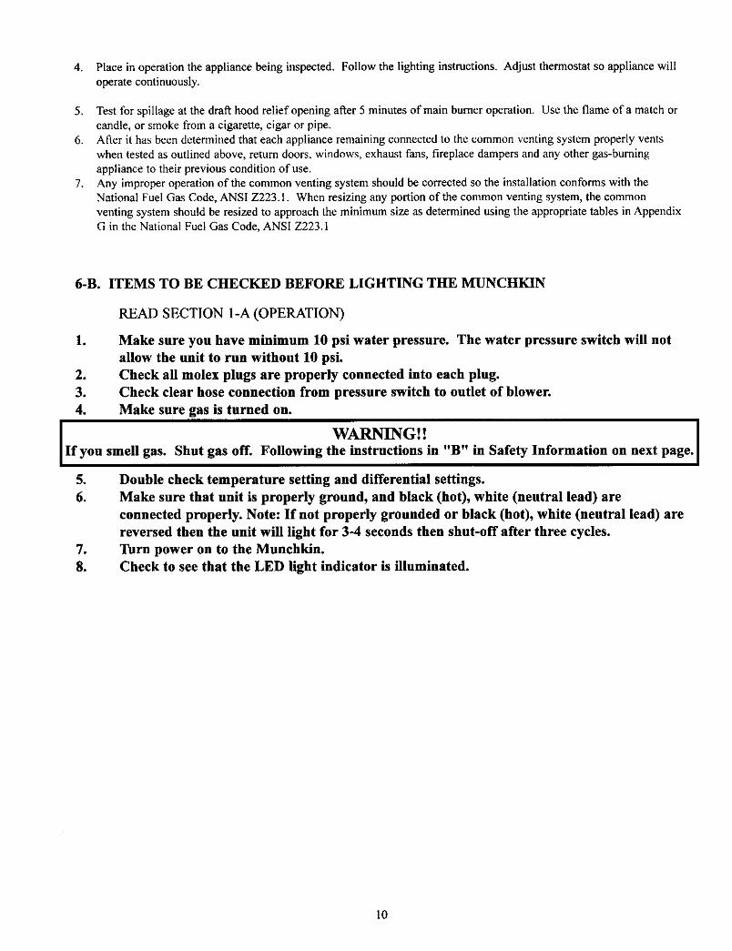
6-B. ITEMS TO BE CHECKED BEFORE LIGHTING THE MUNCHKIN
READ SECTION 1-A (OPERATION)
1
J
3.
4.
Make sure you have minimum 10 psi water pressure. The water pressure switch will not
allow the unit to run without 10 psi.
Check all molex plugs are properly connected into each plug.
Check clear hose connection from pressure switch to outlet of blower.
Make sure gas is turned on.
l If you smell
5.6.
.
8.
WARNING! ! Igas. Shut gas off. Following the instructions in "B" in Safety Information on next page.
Double check temperature setting and differential settings.
Make sure that unit is properly ground, and black (hot), white (neutral lead) areconnected properly. Note: If not properly grounded or black (hot), white (neutral lead) are
reversed then the unit will light for 3-4 seconds then shut-off after three cycles.Turn power on to the Munchkin.Check to see that the LED light indicator is illuminated.
10
6-C. LIGHTING INSTRUCTIONS
[ FOR YOUR SAFETY READ BEFORE OPERATING
m.
B.
C.
D.
I1.2.3.4.
5.
6.7.
8.
9.10.11.12.
_ WARNING!! IIf you do not follow these instructions exactly, a fire or explosion may
result, causing property damage, personal injury or loss of life.
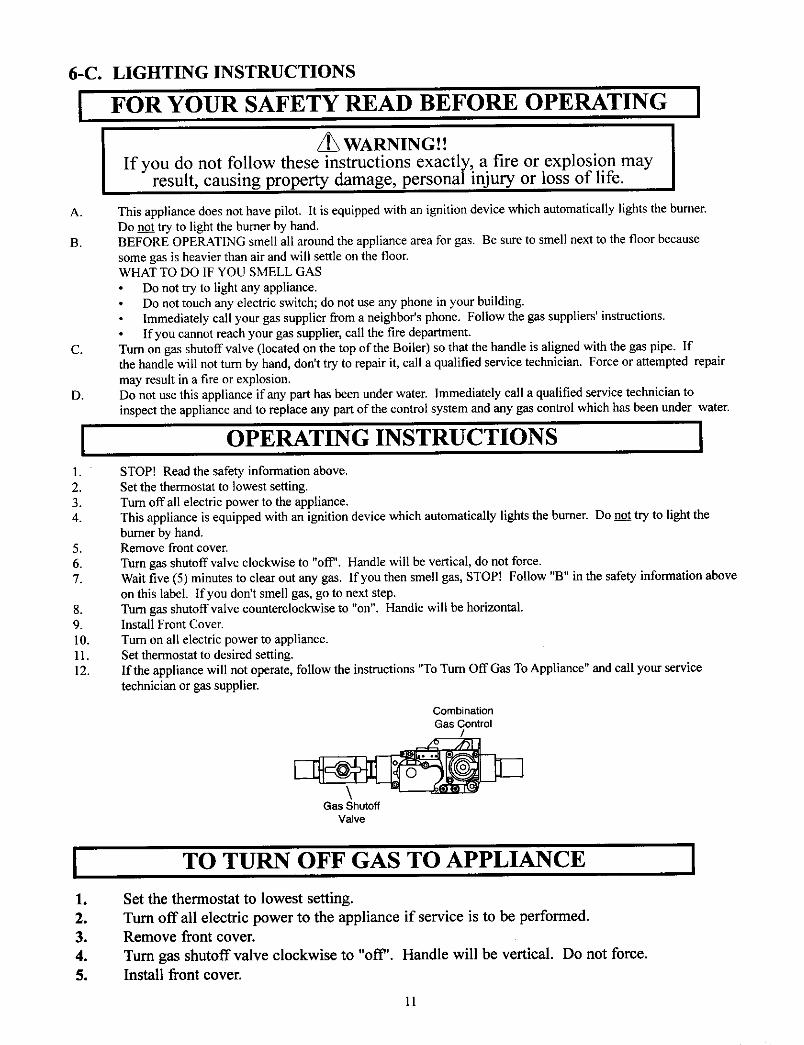
This appliance does not have pilot. It is equipped with an ignition device which automatically lights the burner.Do not try to light the burner by hand.BEFORE OPERATING smell all around the appliance area for gas. Be sure to smell next to the floor becausesome gas is heavier than air and will settle on the floor.WHAT TO DO IF YOU SMELL GAS
Do not try to light any appliance.Do not touch any electric switch; do not use any phone in your building.Immediately call your gas supplier from a neighbor's phone. Follow the gas suppliers' instructions.If you cannot reach your gas supplier, call the fire department.
Turn on gas shutoffvalve (located on the top of the Boiler) so that the handle is aligned with the gas pipe. Ifthe handle will not turn by hand, don't try to repair it, call a qualified service technician. Force or attempted repair
may result in a fire or explosion.Do not use this appliance if any part has been under water. Immediately call a qualified service technician toinspect the appliance and to replace any part of the control system and any gas control which has been under water.
OPERATING INSTRUCTIONS [
STOP[ Read the safety information above.Set the thermostat to lowest setting.Turn offall electric power to the appliance.This appliance is equipped with an ignition device which automatically lights the burner. Do not try to light theburner by hand.Remove front cover.Turn gas shntoffvalve clockwise to "off'. Handle will be vertical, do not force.Wait five (5) minutes to clear out any gas. If you then smell gas, STOP! Follow "B" in the safety information aboveon this label. If you don't smell gas, go to next step.Turn gas shutoff valve counterclockwise to "on". Handle will be horizontal.Install Front Cover.
Turn on all electric power to appliance.Set thermostat to desired setting.If the appliance will not operate, follow the instructions "To Turn Off Gas To Appliance" and call your servicetechnician or gas supplier.
CombinationGas Control
/
Gas ShutoffValve
I1.2.3.
4.
5.
TO TURN OFF GAS TO APPLIANCE I
Set the thermostat to lowest setting.
Turn off all electric power to the appliance if service is to be performed.Remove front cover.
Turn gas shutoff valve clockwise to "off'. Handle will be vertical. Do not force.
Install front cover.
11

PART 7SERVICING
7-A. SEQUENCE OF OPERATION
1. When power is first applied to the control, the control will initially run through a self-diagnostic routine, and then gointo its operating mode. If there is no call for heat, the System will go into the idle state.
2. If the thermostat is calling for heat, the control will apply power to the circulator pump. If the control determines the
appliance water temperature is below the programmed set point value less the switching differential, the control willinitiate a heating cycle.
3. The control then performs selected system diagnostic checks. If all checks are successfully passed, a pre-purge cycle is
initiated (blower on max speed).4. When the pre-purge period is complete, power is applied to the spark ignitor for approximately 6 seconds.
Approximately 2 seconds later, we verify flame. Ifa flame is not verified during the trial-for-ignition, the gas valve isimmediately closed, and the control will return to step 2. If after three trials a flame is not verified, the control will gointo lockout mode. Ifa flame is confirmed, the control enters the heating mode. Fire rate based on the proprietary
algorithm.5. When water temperature reaches the temperature set point valve plus 10 degrees F (or if the thermostat call-for-heat is
satisfied), the gas valve is closed and the control enters post-purge (blower on max speed). NOTE: IF THETHERMOSTAT IS STILL CALLING FOR HEAT, THE CIRCULATOR PUMP WILL CONTINUE TO RUNUNTIL THE THERMOSTAT CALL FOR HEAT IS SATISFIED.
6. When post-purge is complete, the control enters the idle state while continuing to monitor temperature and the state ofother system devices. Ira call-for-heat is received, the control will automatically return to step 2 and repeat the entireoperating cycle.
During the idle state and heat state, if the control detects an improper operating state for external devices such as the high-limit switch, the green LED on the control will flash an error code sequence.
7-B. ADJUSTMENT SET POINTS AND DIFFERENTIAL SETTINGS
1. Temperature Adjustment- A potentiometer located on the control board is used to adjust the set point temperature on
the boiler appliance. This can be set between 70 and 210 degrees.
2. Temperature Differential Adjustment - A "DIP" switch is located on the control board. Depending upon the
configuration of the "DIP" switch, the differential selection is 6, 12, 20, or 30. See the figure below for further detail.
NOTE: the differential adjustment is the value below the set point, when the burner will fire. (Example: 190 degree setpoint, 30 degrees differential, burner will not fire until return water drops below 160 degrees and will modulate the flame until190 degrees is reached, then post purge and idle state will be achieved. If at any point "IT is satisfied, the cycle will beinterrupted by post purge and idle state.
CK
1 2
CK CK
1 2 1 2
12orl 112vl
CK
1 2
12
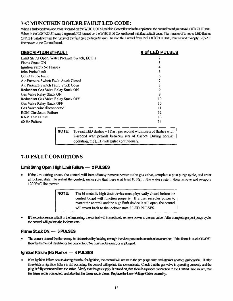
7-C MUNCHKIN BOILER FAULT LED CODE:Wben afault conditionoccut_or isseined onlheWHC 11O0Manchkin ControUeror in theappfiame, tbe _1 _ _ _ a_0_ _.
When in the I£)CKOUT state,tbegreenLED locatedon tixeWHC 1100Controlboardwill flash afanltcode. Thentunber oftimes to LED_ON/OFFwilldetennine thenatureofthe fault(see the tablebelow). ToresettheControlfrom theLOCKOUT state,removeandre-apply 120VACline power to theControlboard.
DESCRIPTION of FAULT
Limit String Open, Water Pressure Switch, ECO'sFlame Stuck ON
Ignition Fault (No Flame)Inlet Probe FaultOutlet Probe Fault
Air Pressure Switch Fault, Stuck ClosedAir Pressure Switch Fault, Stuck OpenRedundant Gas Valve Relay Stuck ONGas Valve Relay Stuck ONRedundant Gas Valve Relay Stuck OFFGas Valve Relay Stuck OFFGas Valve wire disconnectedROM Checksum FailureRAM Test Failure60 Hz Failure
# of LED PULSES
234567899101011121314
NOTE: To readLED flashes - 1 flash per second within sets of flashes with2-second wait periods between sets of flashes. During normal
operation, the LED will pulse continuously.
7-1) FAULT CONDITIONS
Umit StringOpen, High LimitFailure -- 2 PULSES
• If the limit string opens, the control will immediately remove power tothe gas valve, complete a post purge cycle, and enteral lockout state. To restart the control, make sure that there is at least 10 PSI in the water system, then remove and re-apply120 VAC line power.
NOTE:
The bi-metallic high limit device must physically closed before thecontrol board will function properly. If a user recycles power torestart the control, and the high limit device is still open, the controlwill revert back to the lockout state 2 LED PULSES.
Iflhe controlsensesa fanltin the limitstring,the cona_lwiJl immedialely_e ix_wertothe gasvalve. Aftercomp!etingapostptage cycle,thecora_l will go intothe kr.kout slate.
Flame Stuck ON -- 3 PULSES
• Tbecummtstateofthe fl=rtemay be determinedby!ooking6-,nmghlbeview port on tbecombustionchamber. Iflhe tlanaeissl_k ON/OFFtbenthettame md imulatoror the cotmectorCN6 may not be clean,or anplugged.
Ignition Failure (No Flame) -- 4 PULSES
ffan ignitionfaihweocctas d_'ing the trial-for-ignition,the corarolwill rettnn te thepre porge st_ madattempt_ _ _. Ifatterthreetrialsan i_aitionfailtre isstillocctrdng, ttaecontrolwillgo into tbe kr..koutstale. _ thatthegas valve isoperalingconeclly _aadtheplugis fully€(n',_:ted into tbevalve. Vedfy thatthe gas supply is ttrmd on,that thereisa propercora_ctien to the 120VAClinesotnee,_
tbeflamerodiscotuaect_l,m_lalsothattheflanaerodisclean.Replace theLow-Voltage Cableassembly.
13
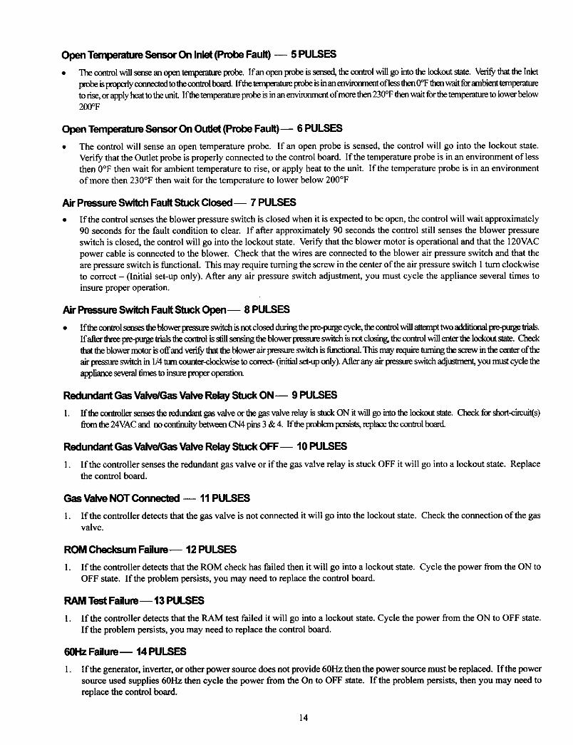
Open Temperature Sensor On Inlet (Probe Fault) -- 5 PULSES
• Thecentrolwillsemeanopentemixamtaelxobe. Ifanolxmprebeissensed, thecontrolwillgo into the lockcot stsle. VerifythattheInlet
ptol_ isixotx:dyconnectedtotheccotrolboard, lfthe t_maperaaaeIxobeis inan mvi_maent ofless tben(YFthenwait forambient temper-,maeto rise,or applyheat tothe tnait Ifthe t(matxratlaeprobe is inan environmentofmore then230°Fthenwait forthe tmll_mtme to towerbelow200°F
Open Temperature Sensor On Outlet (Probe Fault) -- 6 PULSES
The control will sense an open temperature probe. If an open probe is sensed, the control will go into the lockout state.Verify that the Outlet probe is properly connected to the control board. If the temperature probe is in an environment of lessthen 0°F then wait for ambient temperature to rise, or apply heat to the unit. If the temperature probe is in an environment
of more then 230°F then wait for the temperature to lower below 200°F
Air Pressure Switch Fault Stuck Closed-- 7 PULSES
If the control senses the blower pressure switch is closed when it is expected to be open, the control will wait approximately90 seconds for the fault condition to clear. If after approximately 90 seconds the control still senses the blower pressure
switch is closed, the control will go into the lockout state. Verify that the blower motor is operational and that the 120VACpower cable is connected to the blower. Check that the wires are connected to the blower air pressure switch and that theare pressure switch is functional. This may require turning the screw in the center of the air pressure switch 1tom clockwiseto correct - (Initial set-up only). After any air pressure switch adjustment, you must cycle the appliance several times toinsure proper operation.
Air Pressure Switch Fault Stuck Open -- 8 PULSES
lflhe cor_l sensestheblowerpressaneswitchis rt_ cl¢_,eddtring the tre-ptwgecycle,lhe_1 _ _ _ _ _ _.Ifatter ttweewe-ptrg_ Irialstlaecon_ol isstillsensing(heblowerWesst_ switchis not c_ _ _1 _ _ _ 1_o_ _. Checkthat the blowerrnO,or ksoffand verify lhatfiaeblower airim_sure switch is functional.Thismay require O.mainglhe screw m_ _ of_air ptessaneswitch in 1/4turncotuaer-c!ockwJseto cunect- ('mitialset-uponly).After any air pressare switchadjusmaent,yco must cycle theappliance seversltimestoinst_ txoperoperation.
Redundant Gas Valve/Gas Valve Relay Stuck ON-- 9 PULSES
1. If_hec_t_uersemes_hetedtax_antgasva_ve_rthegasvalvere_ayisstuck_Nitwi_g_int__ Check for short-cit_t(s)from the24VACand nocorainuitybetweenCN4 pins3 &4. lfthe problempersists,replacelhe controlboard.
Redundant Gas Valve/Gas Valve Relay Stuck OFF-- 10 PULSES
l. If the controller senses the redundant gas valve or if the gas valve relay is stuck OFF it will go into a lockout state. Replacethe control board.
GasValve NOT Connected -- 11 PULSES
1. If the controller detects that the gas valve is not connected it will go into the lockout state. Check the connection of the gasvalve.
ROM Checksum Failure-- 12 PULSES
1. If the controller detects that the ROM check has failed then it will go into a lockout state. Cycle the power from the ON toOFF state. If the problem persists, you may need to replace the control board.
RAM Test Failure-- 13 PULSES
1. If the controller detects that the RAM test failed it will go into a lockout state. Cycle the power from the ON to OFF state.If the problem persists, you may need to replace the control board.
60Hz Failure-- 14 PULSES
1. If the generator, inverter, or other power source does not provide 60Hz then the power source must be replaced. If the power
source used supplies 60Hz then cycle the power from the On to OFF state. If the problem persists, then you may need toreplace the control board.
14
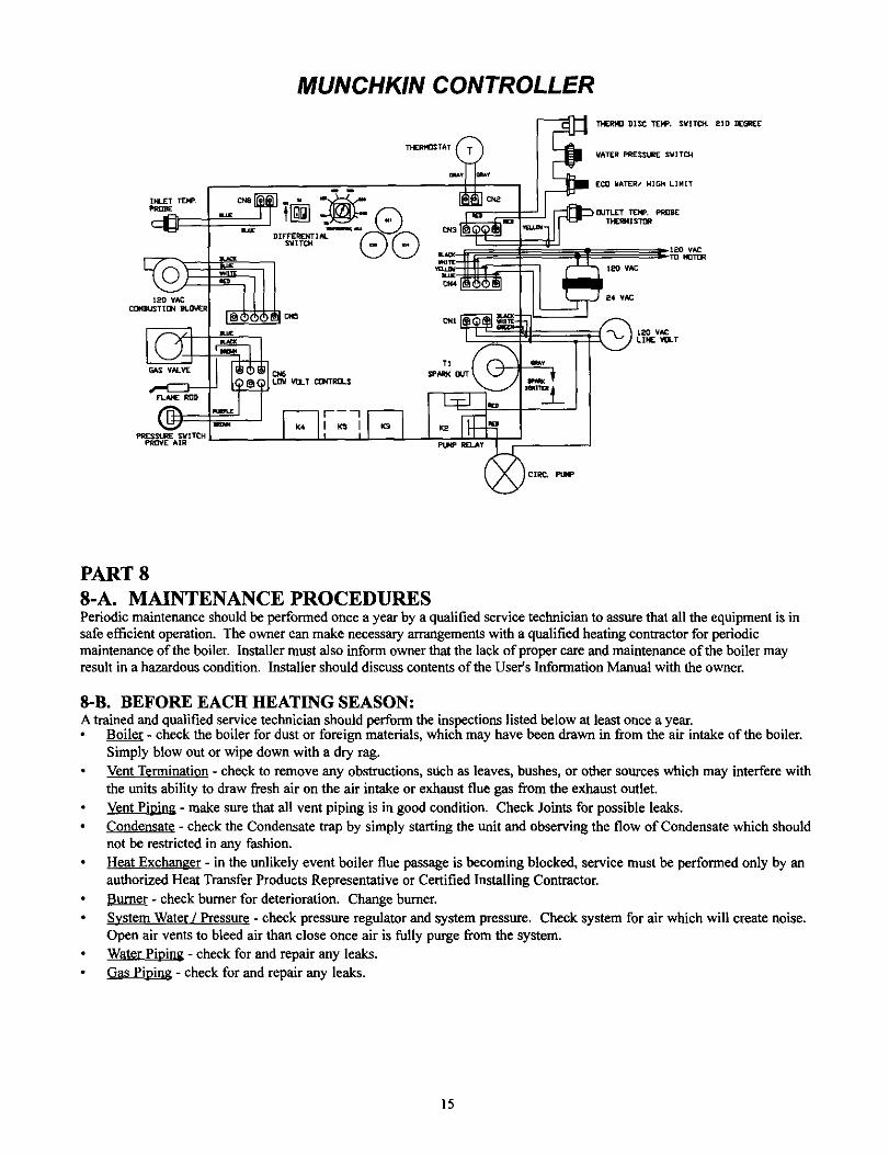
MUNCHKIN CONTROLLER
ICIK_ PUI4P
PART 8
8-A. MAINTENANCE PROCEDURESPeriodic maintenance should be performed once a year by a qualified service technician to assure that all the equipment is insafe efficient operation. The owner can make necessary arrangements with a qualified heating contractor for periodicmaintenance of the boiler. Installer must also inform owner that the lack of proper care and maintenance of the boiler mayresult in a hazardous condition. Installer should discuss contents of the User's Information Manual with the owner.
8-B. BEFORE EACH HEATING SEASON:
A trained and qualified service technician should perform the inspections listed below at least once a yeas.Boiler - check the boiler for dust or foreign materials, which may have been drawn in from the air intake of the boiler.Simply blow out or wipe down with a dry rag.Vent Termination - check to remove any obstructions, such as leaves, bushes, or other sources which may interfere with
the units ability to draw fresh air on the air intake or exhaust flue gas from the exhaust outlet.
Vent Pi_Lo_jag- make sure that all vent piping is in good condition. Check Joints for possible leaks.
- check the Condensate trap by simply starting the unit and observing the flow of Condensate which shouldnot be restricted in any fashion.
Heat Exchanger - in the unlikely event boiler flue passage is becoming blocked, service must be performed only by anauthorized Heat Transfer Products Representative or Certified Installing Contractor.
Burner - check burner for deterioration. Change burner.
System Water / Pressure - check pressure regulator and system pressure. Check system for air which will create noise.Open air vents to bleed air than close once air is fully purge from the system.
Water Pinin_ - cheek for and repair any leaks.
- check for and repair any leaks.
15
/ \
I
ox ÷
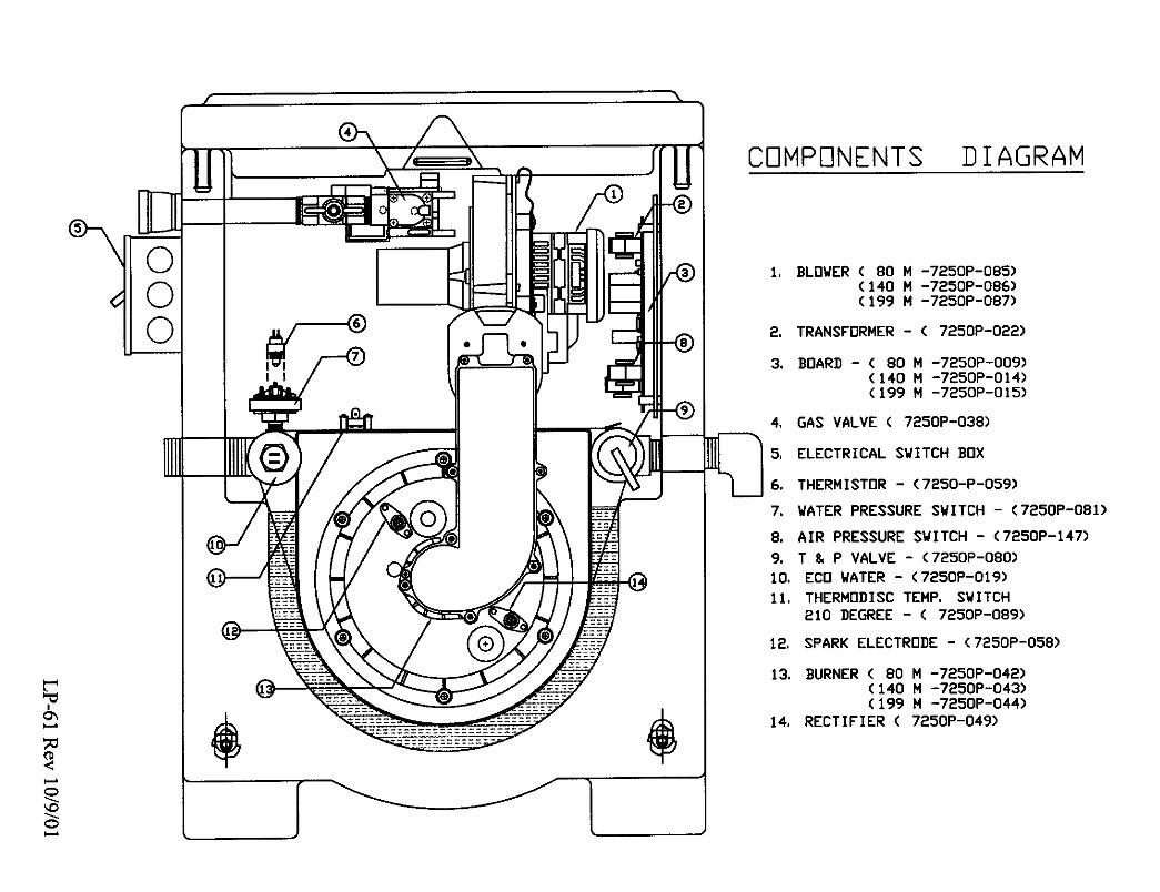
CDMPDNENT$ DIAGRAM
1. BLOWER ( 80 M -7250P-085)(140 M -7250P-086)(199 M -7250P-087)
2. TRANSFORMER - (7250P-022)
3, BOARD - ( 80 M -7250P-009)(140 M -7250P-014)(199 M -7250P-015)
4. GAS VALVE (7250P-038)
5. ELECTRICAL SWITCH BOX
6. THERMISTOR - (7250-P-059)
7. WATER PRESSURE SWITCH - (7250P-081)
B. AIR PRESSURE SWITCH - (7250P-147)
9. T _ P VALVE - (7250P-080)
10. ECO WATER - (7250P-019)
11. THERMODISC TEMP. SWITCH
210 DEGREE - (7250P-089)
12.
13.
14,
SPARK ELECTRODE - (7250P-058)
BURNER ( 80 M -7250P-042)(140 M -7250P-043)(199 M -7250P-044)
RECTIFIER (7250P-049)