Embed Size (px)
Citation preview
Cisco Transport ManaOL-15573-02
C H A P T E R 2
Installing the Cisco Transport Manager High Availability SolutionThis chapter explains how to install CTM in an HA environment. See the Symantec documentation to install Symantec’s Veritas products.
Tip Appendix E, “CTM High Availability Checklists” summarizes the steps in this chapter that are required to perform a CTM HA installation. It is recommended that you print out that appendix and check the appropriate cells as you complete each installation step.
This chapter contains the following sections:
• 2.1 Installing Sun SPARC Solaris 10, page 2-2
• 2.2 Adding System Patches and Configuring the Generic Disk Storage Array, page 2-3
• 2.3 Hardware Configuration, page 2-7
• 2.4 Installing and Configuring Symantec’s Veritas Products, page 2-11
• 2.5 CTM R9.0 and Oracle 10g Installation Prerequisites, page 2-16
• 2.6 Installing the CTM R9.0 Server and Database, page 2-20
• 2.7 Veritas Cluster Server 5.0 Preinstallation Tasks for a Single-Node Cluster, page 2-24
• 2.8 Veritas Cluster Server 5.0 Preinstallation Tasks for a Dual-Node Cluster, page 2-25
• 2.9 Checking the Veritas Cluster Server Agent 5.0 Installation, page 2-27
• 2.10 Installing the CTM Agents, page 2-28
• 2.11 Installing and Configuring Geographical Redundancy—Veritas 5.0, page 2-38
• 2.12 (Optional) Advanced Network Monitoring, page 2-60
• 2.13 Setting Up Sudo, page 2-66
Tip After you complete each of the following procedures, verify the procedure before proceeding to the next one. For example, verify the “2.1 Installing Sun SPARC Solaris 10” procedure before proceeding to the “2.2 Adding System Patches and Configuring the Generic Disk Storage Array” procedure.
2-1ger Release 9.0 High Availability Installation Guide
Chapter 2 Installing the Cisco Transport Manager High Availability Solution2.1 Installing Sun SPARC Solaris 10
2.1 Installing Sun SPARC Solaris 10
Note Verify that all peripherals are integrated on the systems before proceeding. You must install Sun Solaris 10 hardware release 05/08 on both systems. Verify that the hardware release is the same on each node in a local redundancy cluster.
Complete the following steps to install Sun SPARC Solaris 10:
Step 1 Enter the following command to verify the Solaris 10 hardware release:
cat /etc/release
In the output, you should see:
#cat /etc/release Solaris 10 5/08 s10s_u5wos_10 SPARC Copyright 2008 Sun Microsystems, Inc. All Rights Reserved. Use is subject to license terms. Assembled 24 March 2008
Step 2 Enter the following command to halt the system:
sync;sync;sync;halt
Step 3 Enter the following command to edit nvram:
ok {1} setenv use-local-mac-address? true
Step 4 Insert the Solaris 10 Server installation DVD and enter the following command:
ok {2} boot cdrom
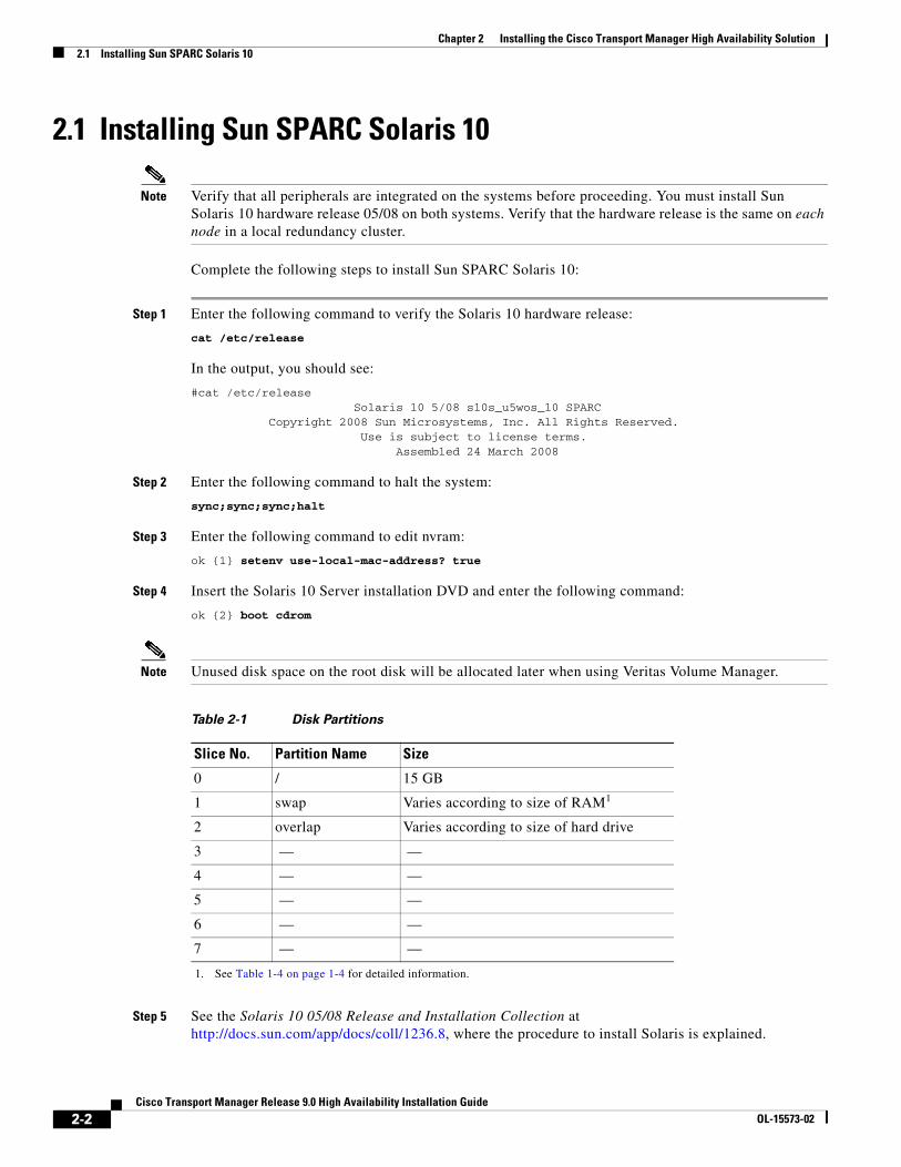
Note Unused disk space on the root disk will be allocated later when using Veritas Volume Manager.
Step 5 See the Solaris 10 05/08 Release and Installation Collection at http://docs.sun.com/app/docs/coll/1236.8, where the procedure to install Solaris is explained.
Table 2-1 Disk Partitions
Slice No. Partition Name Size
0 / 15 GB
1 swap Varies according to size of RAM1
1. See Table 1-4 on page 1-4 for detailed information.
2 overlap Varies according to size of hard drive
3 — —
4 — —
5 — —
6 — —
7 — —
2-2Cisco Transport Manager Release 9.0 High Availability Installation Guide
OL-15573-02
Chapter 2 Installing the Cisco Transport Manager High Availability Solution2.2 Adding System Patches and Configuring the Generic Disk Storage Array
While installing Solaris 10 05/08 for a CTM installation:
• Do not select IPv6
• Do not select Kerberos Security
• Install the Entire Solaris Software Group Plus OEM Support software group
• Configure disk partitions as shown in Table 2-1
2.2 Adding System Patches and Configuring the Generic Disk Storage Array
To add system patches and configure the generic disk storage array, complete the following steps on both systems, one at a time:
Note Non-Cisco websites referenced in the following procedure are © 1994–2009, Sun Microsystems, Inc. All rights reserved.
Step 1 Verify that you have installed the 120222 and 124916 Solaris patches. The 120222 patch is for the Emulex driver and the 124916 patch is for the sdd driver.
Step 2 After adding the patches, enter the following commands to reboot the system:
sync;sync;sync;haltok reboot -- -r
Step 3 While the system is rebooting, power on the generic disk storage array.
Note When creating two or more logical drives, assign them to different controllers. For example, if you have two logical drives created, assign LG0 to the primary and LG1 to the secondary. This way, each controller is assigned to a logical drive and will individually handle I/O requests to its respective logical drive, thus improving performance. In the event of a controller failure, the surviving controller will take over and handle I/O requests for both logical drives until the failed controller is fixed. There are two configured channels (0 and 4) on both controllers. Attach both nodes to channels 0 and 4. This way, if a channel fails, you should still have access from each node. The dual FC controller that is required to attach a secondary loop cable (loop B) to the internal disks is X6768A.
Tip When completing Step 4 to Step 5, see the documentation supplied with the disk array.
Step 4 Create RAID layout 1+0, where 1 refers to mirroring and 0 refers to striping. If the disk array firmware does not support your particular RAID layout, you can use Solaris or Veritas Volume Managers to create the RAID layout.
Step 5 To maximize performance and maintain redundancy, use both the primary and secondary controllers in the disk array.
2-3Cisco Transport Manager Release 9.0 High Availability Installation Guide
OL-15573-02
Chapter 2 Installing the Cisco Transport Manager High Availability Solution2.2.1 Sample Root Profile
2.2.1 Sample Root ProfileThe following sample shows how a typical profile would appear after the Veritas software is installed:
TERM=vt100HOSTNAME=‘hostname‘EDITOR=viPATH=$PATH:/bin:/usr/sbin:/usr/bin:/usr/openwin/bin:/usr/dt/bin:/usr/lib/vxvm/bin:/opt/VRTSvmsa/bin:/opt/VRTSvcs/bin:/opt/VRTSvxfs/sbin:/usr/lib/fs/vxfs:/etc/fs/vxfs:/etc/vx/bin:/usr/local/binMANPATH=$MANPATH:/opt/VRTS/manPS1="($HOSTNAME) #"export TERM HOSTNAME EDITOR PATH MANPATH PS1
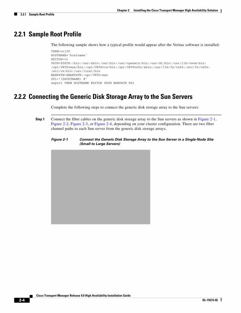
2.2.2 Connecting the Generic Disk Storage Array to the Sun ServersComplete the following steps to connect the generic disk storage array to the Sun servers:
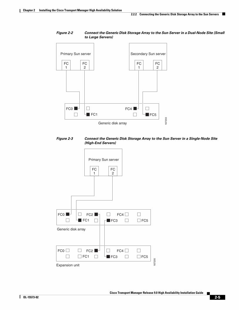
Step 1 Connect the fiber cables on the generic disk storage array to the Sun servers as shown in Figure 2-1, Figure 2-2, Figure 2-3, or Figure 2-4, depending on your cluster configuration. There are two fiber channel paths to each Sun server from the generic disk storage arrays.
Figure 2-1 Connect the Generic Disk Storage Array to the Sun Server in a Single-Node Site
(Small to Large Servers)
2-4Cisco Transport Manager Release 9.0 High Availability Installation Guide
OL-15573-02
Chapter 2 Installing the Cisco Transport Manager High Availability Solution2.2.2 Connecting the Generic Disk Storage Array to the Sun Servers
Figure 2-2 Connect the Generic Disk Storage Array to the Sun Server in a Dual-Node Site (Small
to Large Servers)
Figure 2-3 Connect the Generic Disk Storage Array to the Sun Server in a Single-Node Site
(High-End Servers)
1872
03
Primary Sun server
FC1
FC2
Secondary Sun server
FC1
FC2
Generic disk array
FC0
FC1
FC4
FC5
1872
05
Primary Sun server
FC1
FC2
Generic disk array
FC0
FC1
FC4
FC5
FC2
FC3
Expansion unit
FC0
FC1
FC4
FC5
FC2
FC3
2-5Cisco Transport Manager Release 9.0 High Availability Installation Guide
OL-15573-02
Chapter 2 Installing the Cisco Transport Manager High Availability Solution2.2.2 Connecting the Generic Disk Storage Array to the Sun Servers
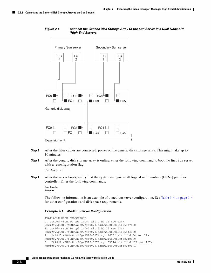
Figure 2-4 Connect the Generic Disk Storage Array to the Sun Server in a Dual-Node Site
(High-End Servers)
Step 2 After the fiber cables are connected, power on the generic disk storage array. This might take up to 10 minutes.
Step 3 After the generic disk storage array is online, enter the following command to boot the first Sun server with a reconfiguration flag:
ok> boot -r
Step 4 After the server boots, verify that the system recognizes all logical unit numbers (LUNs) per fiber controller. Enter the following commands:
devfsadmformat
The following information is an example of a medium server configuration. See Table 1-4 on page 1-4 for other configurations and disk space requirements.
Example 2-1 Medium Server Configuration
AVAILABLE DISK SELECTIONS:0. c1t0d0 <SUN72G cyl 14087 alt 2 hd 24 sec 424>/pci@9,600000/SUNW,qlc@2/fp@0,0/ssd@w500000e010659f71,01. c1t1d0 <SUN72G cyl 14087 alt 2 hd 24 sec 424>/pci@9,600000/SUNW,qlc@2/fp@0,0/ssd@w500000e01065a431,02. c2t40d0 <SUN-StorEdge3510-327R cyl 16382 alt 2 hd 64 sec 32>/pci@8,700000/SUNW,qlc@2/fp@0,0/ssd@w216000c0ff880303,03. c2t40d1 <SUN-StorEdge3510-327R cyl 33344 alt 2 hd 127 sec 127>/pci@8,700000/SUNW,qlc@2/fp@0,0/ssd@w216000c0ff880303,1
1872
04
Primary Sun server
FC1
FC2
Generic disk array
FC0
FC1
FC4
FC5
FC2
FC3
Expansion unit
FC0
FC1
FC4
FC5
FC2
FC3
Secondary Sun server
FC1
FC2
2-6Cisco Transport Manager Release 9.0 High Availability Installation Guide
OL-15573-02
Chapter 2 Installing the Cisco Transport Manager High Availability Solution2.3 Hardware Configuration
4. c2t40d2 <SUN-StorEdge3510-327R cyl 16382 alt 2 hd 64 sec 32>/pci@8,700000/SUNW,qlc@2/fp@0,0/ssd@w216000c0ff880303,25. c2t40d3 <SUN-StorEdge3510-327R cyl 33344 alt 2 hd 127 sec 127>/pci@8,700000/SUNW,qlc@2/fp@0,0/ssd@w216000c0ff880303,36. c4t40d0 <SUN-StorEdge3510-327R cyl 16382 alt 2 hd 64 sec 32>/pci@8,600000/SUNW,qlc@1/fp@0,0/ssd@w216000c0ff880303,07. c4t40d1 <SUN-StorEdge3510-327R cyl 33344 alt 2 hd 127 sec 127>/pci@8,600000/SUNW,qlc@1/fp@0,0/ssd@w216000c0ff880303,18. c4t40d2 <SUN-StorEdge3510-327R cyl 16382 alt 2 hd 64 sec 32>/pci@8,600000/SUNW,qlc@1/fp@0,0/ssd@w216000c0ff880303,29. c4t40d3 <SUN-StorEdge3510-327R cyl 33344 alt 2 hd 127 sec 127>/pci@8,600000/SUNW,qlc@1/fp@0,0/ssd@w216000c0ff880303,3
Note The LUNs on the generic disk must be labeled for Veritas Volume Manager.
Step 5 Enter the following commands to label the generic disk LUNs:
Specify disk (enter its number): 1selecting c1t1d0[disk formatted]Disk not labeled. Label it now? yformat> disk 2selecting c4t44d0[disk formatted]Disk not labeled. Label it now? yformat> disk 3selecting c4t44d1[disk formatted]Disk not labeled. Label it now? yformat> disk 4selecting c4t44d2[disk formatted]Disk not labeled. Label it now? yformat> disk 5selecting c4t44d3[disk formatted]Disk not labeled. Label it now? y
Note Duplicate LUNs are detected because there are two paths to each generic disk volume.
Step 6 After the first server recognizes the generic disk LUNs, enter the following command to boot the second server:
ok> boot -r
The same number of LUNs should be visible as on the first system.
2.3 Hardware ConfigurationThis section describes the different types of hardware configurations available for your HA installation:
• 2.3.1 Local Redundancy Configuration, page 2-8
• 2.3.2 Single-Node Cluster Geographical Redundancy Configuration, page 2-8
2-7Cisco Transport Manager Release 9.0 High Availability Installation Guide
OL-15573-02
Chapter 2 Installing the Cisco Transport Manager High Availability Solution2.3.1 Local Redundancy Configuration
• 2.3.3 Dual-Node Cluster Geographical Redundancy Configuration, page 2-9
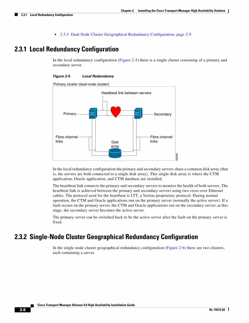
2.3.1 Local Redundancy ConfigurationIn the local redundancy configuration (Figure 2-5) there is a single cluster consisting of a primary and secondary server.
Figure 2-5 Local Redundancy
In the local redundancy configuration the primary and secondary servers share a common disk array (that is, the servers are both connected to a single disk array). This single disk array is where the CTM application, Oracle application, and CTM database are installed.
The heartbeat link connects the primary and secondary servers to monitor the health of both servers. The heartbeat link is achieved between the primary and secondary servers using two cross-over Ethernet cables. The protocol used for the heartbeat is LTT, a Veritas-proprietary protocol. During normal operation, the CTM and Oracle applications run on the primary server (normally the active server). If a fault occurs on the primary server, the CTM and Oracle applications run on the secondary server; at this stage, the secondary server becomes the active server.
The primary server can be switched back to be the active server after the fault on the primary server is fixed.
2.3.2 Single-Node Cluster Geographical Redundancy ConfigurationIn the single-node cluster geographical redundancy configuration (Figure 2-6) there are two clusters, each containing a server.
Primary cluster (dual-node cluster)
SecondaryPrimary
Heartbeat link between servers
Fibre channellinks
Fibre channellinksDisk
array
1808
95
2-8Cisco Transport Manager Release 9.0 High Availability Installation Guide
OL-15573-02
Chapter 2 Installing the Cisco Transport Manager High Availability Solution2.3.3 Dual-Node Cluster Geographical Redundancy Configuration
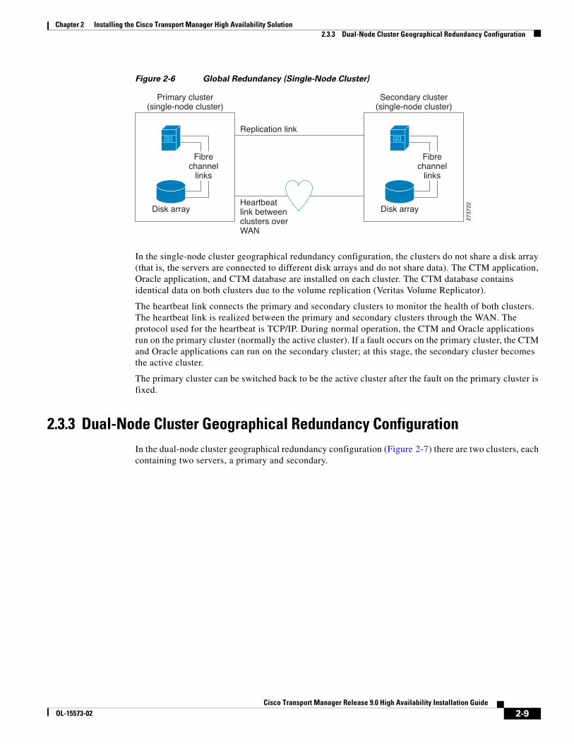
Figure 2-6 Global Redundancy (Single-Node Cluster)
In the single-node cluster geographical redundancy configuration, the clusters do not share a disk array (that is, the servers are connected to different disk arrays and do not share data). The CTM application, Oracle application, and CTM database are installed on each cluster. The CTM database contains identical data on both clusters due to the volume replication (Veritas Volume Replicator).
The heartbeat link connects the primary and secondary clusters to monitor the health of both clusters. The heartbeat link is realized between the primary and secondary clusters through the WAN. The protocol used for the heartbeat is TCP/IP. During normal operation, the CTM and Oracle applications run on the primary cluster (normally the active cluster). If a fault occurs on the primary cluster, the CTM and Oracle applications can run on the secondary cluster; at this stage, the secondary cluster becomes the active cluster.
The primary cluster can be switched back to be the active cluster after the fault on the primary cluster is fixed.
2.3.3 Dual-Node Cluster Geographical Redundancy ConfigurationIn the dual-node cluster geographical redundancy configuration (Figure 2-7) there are two clusters, each containing two servers, a primary and secondary.
2737
22
Fibrechannel
links
Disk array
Primary cluster(single-node cluster)
Fibrechannel
links
Disk array
Secondary cluster(single-node cluster)
Replication link
Heartbeatlink betweenclusters overWAN
2-9Cisco Transport Manager Release 9.0 High Availability Installation Guide
OL-15573-02
Chapter 2 Installing the Cisco Transport Manager High Availability Solution2.3.3 Dual-Node Cluster Geographical Redundancy Configuration
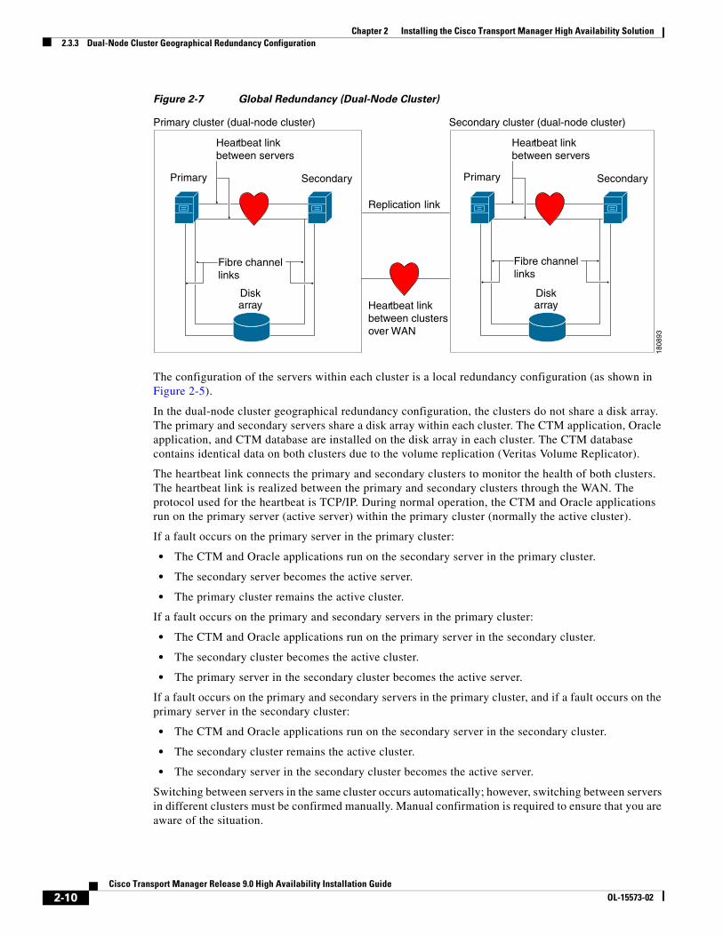
Figure 2-7 Global Redundancy (Dual-Node Cluster)
The configuration of the servers within each cluster is a local redundancy configuration (as shown in Figure 2-5).
In the dual-node cluster geographical redundancy configuration, the clusters do not share a disk array. The primary and secondary servers share a disk array within each cluster. The CTM application, Oracle application, and CTM database are installed on the disk array in each cluster. The CTM database contains identical data on both clusters due to the volume replication (Veritas Volume Replicator).
The heartbeat link connects the primary and secondary clusters to monitor the health of both clusters. The heartbeat link is realized between the primary and secondary clusters through the WAN. The protocol used for the heartbeat is TCP/IP. During normal operation, the CTM and Oracle applications run on the primary server (active server) within the primary cluster (normally the active cluster).
If a fault occurs on the primary server in the primary cluster:
• The CTM and Oracle applications run on the secondary server in the primary cluster.
• The secondary server becomes the active server.
• The primary cluster remains the active cluster.
If a fault occurs on the primary and secondary servers in the primary cluster:
• The CTM and Oracle applications run on the primary server in the secondary cluster.
• The secondary cluster becomes the active cluster.
• The primary server in the secondary cluster becomes the active server.
If a fault occurs on the primary and secondary servers in the primary cluster, and if a fault occurs on the primary server in the secondary cluster:
• The CTM and Oracle applications run on the secondary server in the secondary cluster.
• The secondary cluster remains the active cluster.
• The secondary server in the secondary cluster becomes the active server.
Switching between servers in the same cluster occurs automatically; however, switching between servers in different clusters must be confirmed manually. Manual confirmation is required to ensure that you are aware of the situation.
Primary cluster (dual-node cluster)
SecondaryPrimary
Heartbeat linkbetween servers
Fibre channellinks
Secondary cluster (dual-node cluster)
Disk
SecondaryPrimary
Heartbeat linkbetween servers
Fibre channellinks
Heartbeat linkbetween clustersover WAN
Replication link
Diskarray
Diskarray
1808
93
2-10Cisco Transport Manager Release 9.0 High Availability Installation Guide
OL-15573-02
Chapter 2 Installing the Cisco Transport Manager High Availability Solution2.4 Installing and Configuring Symantec’s Veritas Products
The primary cluster can be switched back to be the active cluster after the fault on the primary cluster is fixed.
2.4 Installing and Configuring Symantec’s Veritas ProductsBefore you install the Veritas Cluster Server (VCS), obtain the following information:
• A name for each cluster. The name must begin with a letter (a-z, A-Z).
• A unique ID number for each cluster. Within the subnet containing the cluster, each cluster must have a unique ID.
• The hostname(s) of the Sun server(s) in each cluster.
• (For a dual-node cluster only) The device names of the NICs used for the private networks among systems (qfe0 and qfe4).
Also, verify that when you run the installation utility:
• You are logged in as the root user.
• You have remote root access to each of the systems in each cluster from the system where the installation will run.
• The /etc/hosts file contains the names and IP addresses of all of the systems.
Note Symantec’s Veritas documentation can be found at http://www.symantec.com/enterprise/veritas/index.jsp.
Non-Cisco websites referenced in this section are © 1995–2009, Symantec Corporation. All rights reserved.
Tip See Figure 2-5, Figure 2-6, and Figure 2-7 as you complete the procedures in this section.
Install and configure the Veritas Storage Foundation Enterprise HA, 5.0 for Oracle according to the instructions in the following documents:
• Veritas Cluster Server 5.0 for Solaris Installation Guide
• Veritas Storage Foundation, 5.0 Installation Guide
• Veritas Storage Foundation 5.0 Release Notes
Complete the following tasks in the order listed:
Step 1 Verify that rsh is working between each primary and corresponding secondary server to allow the Veritas installation to be accomplished on the secondary server. Enter the following command from the primary server where you are initiating the installation:
rsh hostname "ls -l"
A list of files on the remote workstation should be displayed.
If rsh is not working, create a .rhosts file in the / directory on the remote workstation with the following entry:
cat /.rhosts
2-11Cisco Transport Manager Release 9.0 High Availability Installation Guide
OL-15573-02
Chapter 2 Installing the Cisco Transport Manager High Availability Solution2.4 Installing and Configuring Symantec’s Veritas Products
... machine_name root ...
Step 2 Install and configure Veritas Storage Foundation 5.0 for Oracle on the primary servers using the installation script. After mounting the appropriate disk, start the installation script. If the disk is mounted with Solaris Volume Management, enter the following commands:
cd /cdrom/cdrom0/storage_foundation_for_oracle ./installer -rsh
Note • While installing Veritas Storage Foundation 5.0, if you receive the error “e1000g1 is not a valid NIC name,” patch the system as described on the Veritas support website at http://seer.support.veritas.com/docs/285072.htm. This website is © 1995–2009, Symantec Corporation. All rights reserved.
• When prompted by the installer, choose to install all of the optional packages (option 1), which installs them on all systems. Choosing to install all of the optional packages makes the installation easier and ensures that you have Veritas Enterprise Administrator 5.0, VCS GUI, and Veritas manual pages installed. When prompted by the installer, choose not to configure Cluster Service. It is recommended that you use the VCS GUI. For optimal performance, install and run the VCS GUI (package VRTScscm) and CTM server on separate workstations (or install and run the VCS GUI separately on a PC).
Step 3 Install Veritas Storage Foundation 5.0 Maintenance Pack 1 for Oracle on the primary servers.
Step 4 On all of the servers in single-user mode, enter the following command to install the Veritas Storage Foundation 5.0 Maintenance Pack 1 Rolling Patch 5 (RP5), available at http://seer.entsupport.symantec.com/docs/308167.htm:
patchadd -M . 123742-04 124361-06 127344-01
Step 5 Reboot the servers.
Step 6 Enter the following command to verify that Veritas recognizes your particular disk array model:
vxddladm listsupport | grep <disk_array_model>
In the output, you should see the model name of your disk array.
Step 7 Complete the following substeps to use enclosure-based names:
a. Enter the following command:
vxdiskadm
b. Choose the following option:
20 Change the disk naming scheme
c. Answer yes at the question “Do you want to change the disk naming scheme?”
Step 8 Use Solaris Volume Manager or Veritas Volume Manager to mirror the root disk. See the following documentation:
• Solaris Volume Manager: http://docs.sun.com/app/docs/doc/816-4520
• Veritas Volume Manager: http://docs.sun.com/app/docs/doc/875-3890-10
2-12Cisco Transport Manager Release 9.0 High Availability Installation Guide
OL-15573-02
Chapter 2 Installing the Cisco Transport Manager High Availability Solution2.4 Installing and Configuring Symantec’s Veritas Products
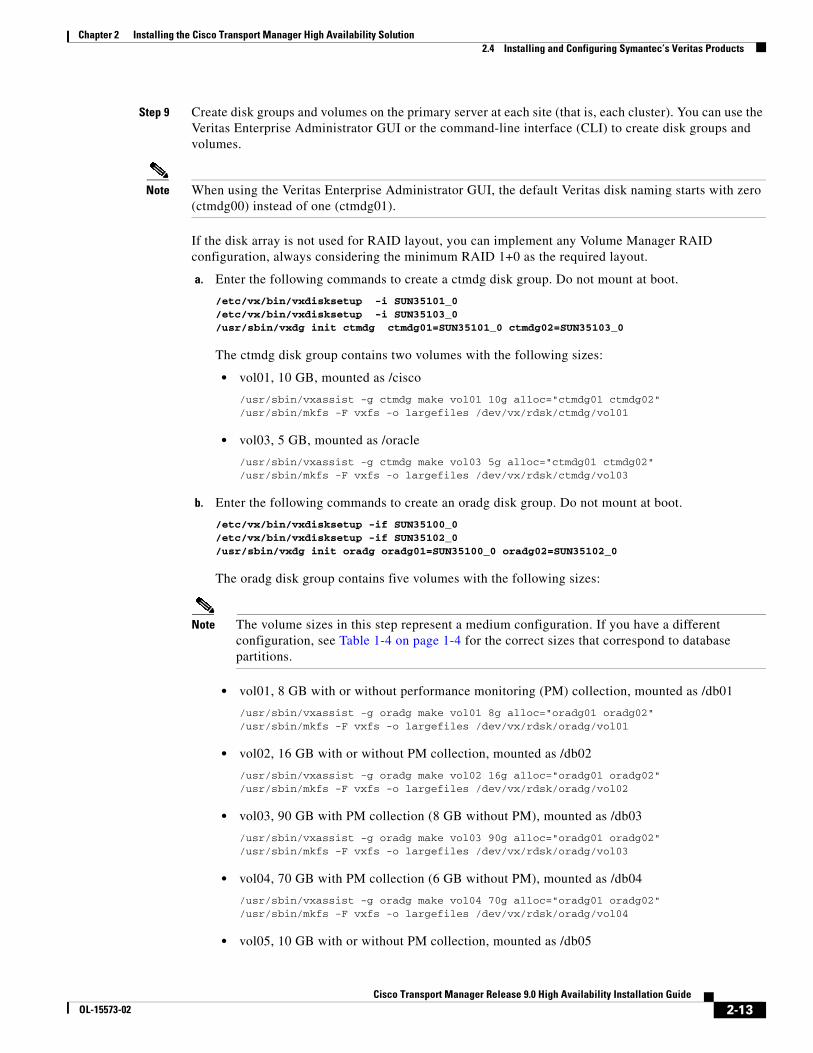
Step 9 Create disk groups and volumes on the primary server at each site (that is, each cluster). You can use the Veritas Enterprise Administrator GUI or the command-line interface (CLI) to create disk groups and volumes.
Note When using the Veritas Enterprise Administrator GUI, the default Veritas disk naming starts with zero (ctmdg00) instead of one (ctmdg01).
If the disk array is not used for RAID layout, you can implement any Volume Manager RAID configuration, always considering the minimum RAID 1+0 as the required layout.
a. Enter the following commands to create a ctmdg disk group. Do not mount at boot.
/etc/vx/bin/vxdisksetup -i SUN35101_0/etc/vx/bin/vxdisksetup -i SUN35103_0/usr/sbin/vxdg init ctmdg ctmdg01=SUN35101_0 ctmdg02=SUN35103_0
The ctmdg disk group contains two volumes with the following sizes:
• vol01, 10 GB, mounted as /cisco
/usr/sbin/vxassist -g ctmdg make vol01 10g alloc="ctmdg01 ctmdg02"/usr/sbin/mkfs -F vxfs -o largefiles /dev/vx/rdsk/ctmdg/vol01
• vol03, 5 GB, mounted as /oracle
/usr/sbin/vxassist -g ctmdg make vol03 5g alloc="ctmdg01 ctmdg02"/usr/sbin/mkfs -F vxfs -o largefiles /dev/vx/rdsk/ctmdg/vol03
b. Enter the following commands to create an oradg disk group. Do not mount at boot.
/etc/vx/bin/vxdisksetup -if SUN35100_0/etc/vx/bin/vxdisksetup -if SUN35102_0/usr/sbin/vxdg init oradg oradg01=SUN35100_0 oradg02=SUN35102_0
The oradg disk group contains five volumes with the following sizes:
Note The volume sizes in this step represent a medium configuration. If you have a different configuration, see Table 1-4 on page 1-4 for the correct sizes that correspond to database partitions.
• vol01, 8 GB with or without performance monitoring (PM) collection, mounted as /db01
/usr/sbin/vxassist -g oradg make vol01 8g alloc="oradg01 oradg02"/usr/sbin/mkfs -F vxfs -o largefiles /dev/vx/rdsk/oradg/vol01
• vol02, 16 GB with or without PM collection, mounted as /db02
/usr/sbin/vxassist -g oradg make vol02 16g alloc="oradg01 oradg02"/usr/sbin/mkfs -F vxfs -o largefiles /dev/vx/rdsk/oradg/vol02
• vol03, 90 GB with PM collection (8 GB without PM), mounted as /db03
/usr/sbin/vxassist -g oradg make vol03 90g alloc="oradg01 oradg02"/usr/sbin/mkfs -F vxfs -o largefiles /dev/vx/rdsk/oradg/vol03
• vol04, 70 GB with PM collection (6 GB without PM), mounted as /db04
/usr/sbin/vxassist -g oradg make vol04 70g alloc="oradg01 oradg02"/usr/sbin/mkfs -F vxfs -o largefiles /dev/vx/rdsk/oradg/vol04
• vol05, 10 GB with or without PM collection, mounted as /db05
2-13Cisco Transport Manager Release 9.0 High Availability Installation Guide
OL-15573-02
Chapter 2 Installing the Cisco Transport Manager High Availability Solution2.4 Installing and Configuring Symantec’s Veritas Products
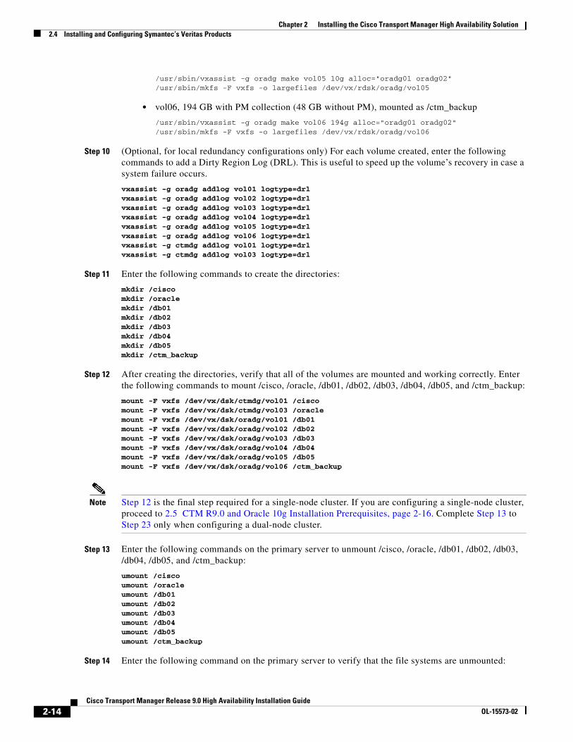
/usr/sbin/vxassist -g oradg make vol05 10g alloc="oradg01 oradg02"/usr/sbin/mkfs -F vxfs -o largefiles /dev/vx/rdsk/oradg/vol05
• vol06, 194 GB with PM collection (48 GB without PM), mounted as /ctm_backup
/usr/sbin/vxassist -g oradg make vol06 194g alloc="oradg01 oradg02"/usr/sbin/mkfs -F vxfs -o largefiles /dev/vx/rdsk/oradg/vol06
Step 10 (Optional, for local redundancy configurations only) For each volume created, enter the following commands to add a Dirty Region Log (DRL). This is useful to speed up the volume’s recovery in case a system failure occurs.
vxassist -g oradg addlog vol01 logtype=drlvxassist -g oradg addlog vol02 logtype=drlvxassist -g oradg addlog vol03 logtype=drlvxassist -g oradg addlog vol04 logtype=drlvxassist -g oradg addlog vol05 logtype=drlvxassist -g oradg addlog vol06 logtype=drlvxassist -g ctmdg addlog vol01 logtype=drlvxassist -g ctmdg addlog vol03 logtype=drl
Step 11 Enter the following commands to create the directories:
mkdir /ciscomkdir /oraclemkdir /db01mkdir /db02mkdir /db03mkdir /db04mkdir /db05mkdir /ctm_backup
Step 12 After creating the directories, verify that all of the volumes are mounted and working correctly. Enter the following commands to mount /cisco, /oracle, /db01, /db02, /db03, /db04, /db05, and /ctm_backup:
mount -F vxfs /dev/vx/dsk/ctmdg/vol01 /ciscomount -F vxfs /dev/vx/dsk/ctmdg/vol03 /oraclemount -F vxfs /dev/vx/dsk/oradg/vol01 /db01mount -F vxfs /dev/vx/dsk/oradg/vol02 /db02mount -F vxfs /dev/vx/dsk/oradg/vol03 /db03mount -F vxfs /dev/vx/dsk/oradg/vol04 /db04mount -F vxfs /dev/vx/dsk/oradg/vol05 /db05mount -F vxfs /dev/vx/dsk/oradg/vol06 /ctm_backup
Note Step 12 is the final step required for a single-node cluster. If you are configuring a single-node cluster, proceed to 2.5 CTM R9.0 and Oracle 10g Installation Prerequisites, page 2-16. Complete Step 13 to Step 23 only when configuring a dual-node cluster.
Step 13 Enter the following commands on the primary server to unmount /cisco, /oracle, /db01, /db02, /db03, /db04, /db05, and /ctm_backup:
umount /ciscoumount /oracleumount /db01umount /db02umount /db03umount /db04umount /db05umount /ctm_backup
Step 14 Enter the following command on the primary server to verify that the file systems are unmounted:
2-14Cisco Transport Manager Release 9.0 High Availability Installation Guide
OL-15573-02
Chapter 2 Installing the Cisco Transport Manager High Availability Solution2.4 Installing and Configuring Symantec’s Veritas Products
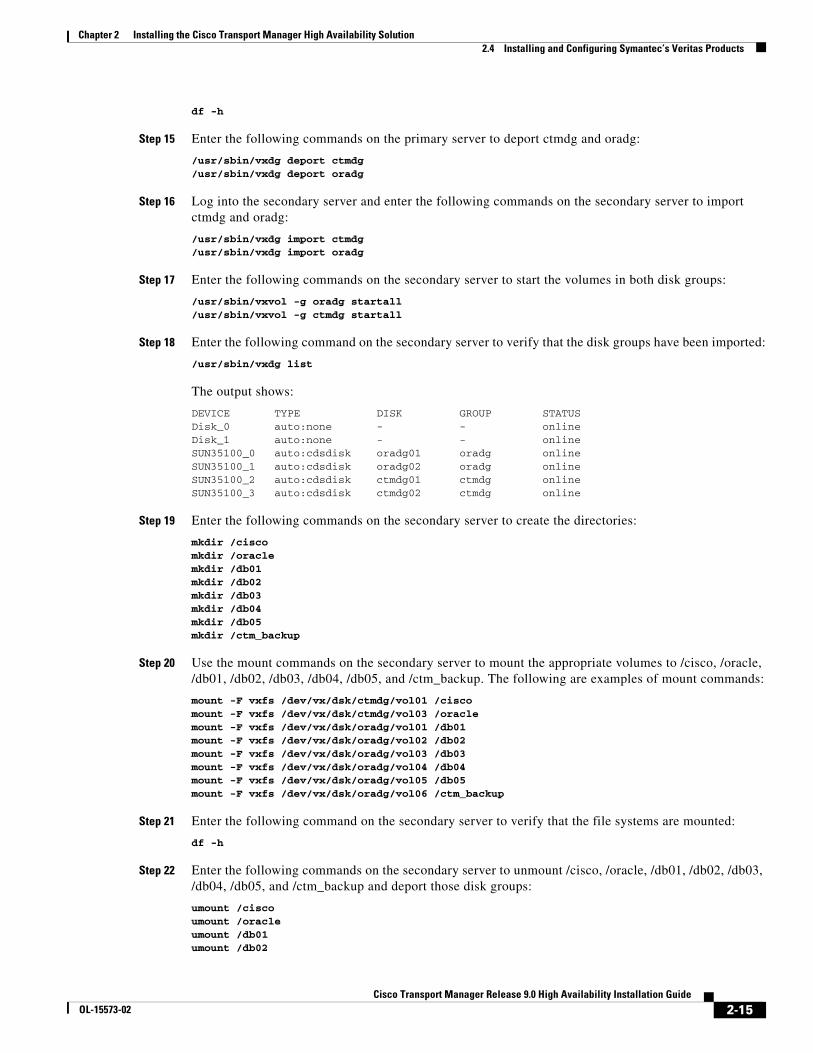
df -h
Step 15 Enter the following commands on the primary server to deport ctmdg and oradg:
/usr/sbin/vxdg deport ctmdg/usr/sbin/vxdg deport oradg
Step 16 Log into the secondary server and enter the following commands on the secondary server to import ctmdg and oradg:
/usr/sbin/vxdg import ctmdg/usr/sbin/vxdg import oradg
Step 17 Enter the following commands on the secondary server to start the volumes in both disk groups:
/usr/sbin/vxvol -g oradg startall/usr/sbin/vxvol -g ctmdg startall
Step 18 Enter the following command on the secondary server to verify that the disk groups have been imported:
/usr/sbin/vxdg list
The output shows:
DEVICE TYPE DISK GROUP STATUSDisk_0 auto:none - - online Disk_1 auto:none - - online SUN35100_0 auto:cdsdisk oradg01 oradg onlineSUN35100_1 auto:cdsdisk oradg02 oradg onlineSUN35100_2 auto:cdsdisk ctmdg01 ctmdg onlineSUN35100_3 auto:cdsdisk ctmdg02 ctmdg online
Step 19 Enter the following commands on the secondary server to create the directories:
mkdir /ciscomkdir /oraclemkdir /db01mkdir /db02mkdir /db03mkdir /db04mkdir /db05mkdir /ctm_backup
Step 20 Use the mount commands on the secondary server to mount the appropriate volumes to /cisco, /oracle, /db01, /db02, /db03, /db04, /db05, and /ctm_backup. The following are examples of mount commands:
mount -F vxfs /dev/vx/dsk/ctmdg/vol01 /ciscomount -F vxfs /dev/vx/dsk/ctmdg/vol03 /oraclemount -F vxfs /dev/vx/dsk/oradg/vol01 /db01mount -F vxfs /dev/vx/dsk/oradg/vol02 /db02mount -F vxfs /dev/vx/dsk/oradg/vol03 /db03mount -F vxfs /dev/vx/dsk/oradg/vol04 /db04mount -F vxfs /dev/vx/dsk/oradg/vol05 /db05mount -F vxfs /dev/vx/dsk/oradg/vol06 /ctm_backup
Step 21 Enter the following command on the secondary server to verify that the file systems are mounted:
df -h
Step 22 Enter the following commands on the secondary server to unmount /cisco, /oracle, /db01, /db02, /db03, /db04, /db05, and /ctm_backup and deport those disk groups:
umount /ciscoumount /oracleumount /db01umount /db02
2-15Cisco Transport Manager Release 9.0 High Availability Installation Guide
OL-15573-02
Chapter 2 Installing the Cisco Transport Manager High Availability Solution2.5 CTM R9.0 and Oracle 10g Installation Prerequisites
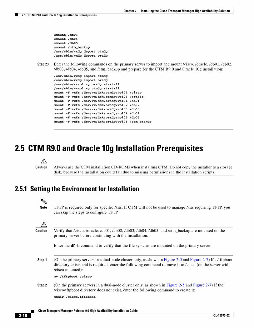
umount /db03umount /db04umount /db05umount /ctm_backup/usr/sbin/vxdg deport ctmdg/usr/sbin/vxdg deport oradg
Step 23 Enter the following commands on the primary server to import and mount /cisco, /oracle, /db01, /db02, /db03, /db04, /db05, and /ctm_backup and prepare for the CTM R9.0 and Oracle 10g installation:
/usr/sbin/vxdg import ctmdg/usr/sbin/vxdg import oradg/usr/sbin/vxvol -g oradg startall/usr/sbin/vxvol -g ctmdg startallmount -F vxfs /dev/vx/dsk/ctmdg/vol01 /ciscomount -F vxfs /dev/vx/dsk/ctmdg/vol03 /oraclemount -F vxfs /dev/vx/dsk/oradg/vol01 /db01mount -F vxfs /dev/vx/dsk/oradg/vol02 /db02mount -F vxfs /dev/vx/dsk/oradg/vol03 /db03mount -F vxfs /dev/vx/dsk/oradg/vol04 /db04mount -F vxfs /dev/vx/dsk/oradg/vol05 /db05mount -F vxfs /dev/vx/dsk/oradg/vol06 /ctm_backup
2.5 CTM R9.0 and Oracle 10g Installation Prerequisites
Caution Always use the CTM installation CD-ROMs when installing CTM. Do not copy the installer to a storage disk, because the installation could fail due to missing permissions in the installation scripts.
2.5.1 Setting the Environment for Installation
Note TFTP is required only for specific NEs. If CTM will not be used to manage NEs requiring TFTP, you can skip the steps to configure TFTP.
Caution Verify that /cisco, /oracle, /db01, /db02, /db03, /db04, /db05, and /ctm_backup are mounted on the primary server before continuing with the installation.
Enter the df -h command to verify that the file systems are mounted on the primary server.
Step 1 (On the primary servers in a dual-node cluster only, as shown in Figure 2-5 and Figure 2-7) If a /tftpboot directory exists and is required, enter the following command to move it to /cisco (on the server with /cisco mounted):
mv /tftpboot /cisco
Step 2 (On the primary servers in a dual-node cluster only, as shown in Figure 2-5 and Figure 2-7) If the /cisco/tftpboot directory does not exist, enter the following command to create it:
mkdir /cisco/tftpboot
2-16Cisco Transport Manager Release 9.0 High Availability Installation Guide
OL-15573-02
Chapter 2 Installing the Cisco Transport Manager High Availability Solution2.5.1 Setting the Environment for Installation
Step 3 (On all servers in a dual-node cluster only, as shown in Figure 2-5 and Figure 2-7) Enter the following command to create links to /cisco/tftpboot:
ln -s /cisco/tftpboot /tftpboot
Step 4 (In a single-node cluster only, as shown in Figure 2-6) If the /tftpboot directory does not exist, enter the following command to create it:
mkdir /tftpboot
Step 5 (On all servers, as shown in Figure 2-5, Figure 2-6, and Figure 2-7) Edit the /etc/inetd.conf file and set the TFTP environment to /tftpboot by uncommenting the TFTP service line.
a. Verify that the TFTP entry in the /etc/inetd.conf file is not commented. The following example represents a typical TFTP entry in the /etc/inetd.conf file. In this example, the TFTP directory is /tftpboot:
tftp dgram udp6 wait root /usr/sbin/in.tftpd in.tftpd -s /tftpboot
b. If the TFTP entry is commented, remove the pound sign (#) at the beginning of the line to uncomment it.
c. Enter the following command to import the service into the Solaris 10 Service Management Framework (SMF):
inetconv
d. Enter the following command to verify that the TFTP service is enabled and working correctly:
svcs |grep tftp
The output shows:
online 10:37:38 svc:/network/tftp/udp6:default
Note The db05 directory is required only if the database is in ARCHIVELOG mode. If archiving will not be used, volume vol05 is not required.
Step 6 (On all servers, as shown in Figure 2-5, Figure 2-6, and Figure 2-7) Enter the following command to create a UNIX group for database administrators:
groupadd -g 3303 dba
Step 7 (On all servers, as shown in Figure 2-5, Figure 2-6, and Figure 2-7) Enter the following command to create a UNIX group for installation of the Oracle software:
groupadd oinstall
Step 8 (On all servers, as shown in Figure 2-5, Figure 2-6, and Figure 2-7) Enter the following command to create a UNIX account to own the Oracle software:
useradd -g oinstall -G dba -m -s /bin/csh -d /oracle oracle
Caution The oracle user must set the home directory to /oracle. If the home directory is not set to /oracle, the Oracle software might not start.
Step 9 (On all servers, as shown in Figure 2-5, Figure 2-6, and Figure 2-7) Enter the following command to change the oracle user password:
2-17Cisco Transport Manager Release 9.0 High Availability Installation Guide
OL-15573-02
Chapter 2 Installing the Cisco Transport Manager High Availability Solution2.5.2 Installing Oracle 10g
passwd oracle
Step 10 (On all servers, as shown in Figure 2-5, Figure 2-6, and Figure 2-7) Enter the new password; then, re-enter the password to confirm it.
Step 11 (On the secondary servers in a dual-node cluster only, as shown in Figure 2-5 and Figure 2-7) Enter the following commands to add the correct users to “dba”:
usermod -G dba daemonusermod -G dba adm
2.5.2 Installing Oracle 10gComplete the steps in this section only on the primary servers in dual-node clusters as shown in Figure 2-5 and Figure 2-7, or on all servers in single-node clusters as shown in Figure 2-6.
Step 1 Insert the CTM Server Disk 1 installation CD and enter the following command:
cd /cdrom/cdrom0/Disk1
Step 2 Enter the following command to list the files in the cdrom/cdrom0/Disk1 directory:
ls -laR
If a list of files is returned, it indicates that you can access the CD-ROM. If no files are visible, or if an error message is returned, see the Sun Solaris documentation for mounting the CD-ROM.
Step 3 Install Oracle 10g. See A.1 Installing Oracle 10g, page A-1.
Note Verify that the STTY command is not used in the shell configuration file; for example, in the .login, .cshrc, or .profile file.
2.5.3 Updating the System Parameters
Caution Verify that /cisco, /oracle, /db01, /db02, /db03, /db04, /db05, and /ctm_backup are mounted on the primary server before continuing with the installation.
Enter the df -h command to verify that the file systems are mounted on the primary server.
To update the system parameters, log in as the root user and complete the following steps on each primary server in each local cluster:
Step 1 If you are using an xterm window or a remote host, enter the following command to set the DISPLAY variable:
setenv DISPLAY <hostname_or_IP_address>:0.0
Step 2 Enter the following command to verify that the display is set correctly:
2-18Cisco Transport Manager Release 9.0 High Availability Installation Guide
OL-15573-02
Chapter 2 Installing the Cisco Transport Manager High Availability Solution2.5.3 Updating the System Parameters
echo $DISPLAY
In the output, you should see:
<hostname_or_IP_address>:0.0
Step 3 Insert the CTM Server Disk 1 installation CD and enter the following commands:
cd /cdrom/cdrom0/Disk1/ctmsetup.sh
The setup program searches for Sun Microsystems Java Runtime Environment (JRE) version 1.5.0_17 on your workstation.
Note If JRE is not installed, the setup program starts the Java installation program. Enter yes at the following binary license code agreement prompt; then, continue this procedure:Do you agree to the above license terms? [yes or no]
Wait for up to 60 seconds while the following message appears:
Please wait, Cisco Transport Manager Server Release 9.0 is being configured for your system. This may take a moment...
Step 4 Click Next at the Introduction screen.
Step 5 At the License Agreement screen, read the license agreement and click the I accept the terms of license agreement radio button; then, click Next.
Step 6 At the Installation Options screen, choose New installation; then, click Next.
Step 7 At the Select Products to Install screen, complete the following substeps:
a. Check the following check boxes:
• Cisco Transport Manager server
• (For a dual-node cluster only, as shown in Figure 2-5 and Figure 2-7) High Availability Installation
Caution If you are using a single-node cluster (Figure 2-6), do not check the High Availability Installation check box.
b. (For a dual-node cluster only, as shown in Figure 2-5 and Figure 2-7) In the Second HA Server field, enter the IP address or hostname of the secondary HA server.
c. Click Next.
d. (For a dual-node cluster only, as shown in Figure 2-5 and Figure 2-7) Click OK in the dialog box that contains the following text:
Verification of second HA server may take a few seconds. Please wait.
Step 8 At the Select Modules to Install screen, select individual modules; then, click Next.
Step 9 At the Main Options screen, check only the Check system settings check box; then, click Next.
Caution Do not check the other check boxes on the Main Options screen. You will check the other options during the next phase of the installation.
2-19Cisco Transport Manager Release 9.0 High Availability Installation Guide
OL-15573-02
Chapter 2 Installing the Cisco Transport Manager High Availability Solution2.6 Installing the CTM R9.0 Server and Database
Step 10 At the Select Network Configuration screen, specify the size of your network; then, click Next.
Step 11 At the Update the System Parameters screen, check the following check boxes; then, click Next:
• Optimize CTM database parameters
• Optimize CTM server parameters
Step 12 At the warning prompt, click Exit Setup.
Note The warning prompt appears only the first time the CTM software is installed.
Step 13 Reboot each server in the cluster.
2.6 Installing the CTM R9.0 Server and DatabaseTo install the CTM R9.0 server and database, log in as the root user and complete the following steps on the primary server at each site (that is, in each cluster):
Step 1 Enter the following commands to manually import the ctmdg disk group and start all volumes:
/usr/sbin/vxdg import ctmdg /usr/sbin/vxdg import oradg /usr/sbin/vxvol -g ctmdg startall/usr/sbin/vxvol -g oradg startall
Step 2 Enter the following commands to manually mount /cisco, /oracle, /db01, /db02, /db03, /db04, and /db05:
mount -F vxfs /dev/vx/dsk/ctmdg/vol01 /ciscomount -F vxfs /dev/vx/dsk/ctmdg/vol03 /oraclemount -F vxfs /dev/vx/dsk/oradg/vol01 /db01mount -F vxfs /dev/vx/dsk/oradg/vol02 /db02mount -F vxfs /dev/vx/dsk/oradg/vol03 /db03mount -F vxfs /dev/vx/dsk/oradg/vol04 /db04mount -F vxfs /dev/vx/dsk/oradg/vol05 /db05mount -F vxfs /dev/vx/dsk/oradg/vol06 /ctm_backup
Step 3 Enter the following command to verify that the file systems are mounted:
df -h
Step 4 (For a dual-node cluster only, as shown in Figure 2-5 and Figure 2-7) Enter the following command to plumb the virtual interface:
ifconfig qfe1:1 plumb
Step 5 (For a dual-node cluster only, as shown in Figure 2-5 and Figure 2-7) Enter the following command to configure the virtual interface:
ifconfig qfe1:1 <virtual_IP_address> netmask <netmask> up
Step 6 Insert the CTM Server Disk 1 installation CD and enter the following commands:
cd /cdrom/cdrom0/Disk1/ctmsetup.sh
Step 7 Click Next at the Introduction screen.
2-20Cisco Transport Manager Release 9.0 High Availability Installation Guide
OL-15573-02
Chapter 2 Installing the Cisco Transport Manager High Availability Solution2.6 Installing the CTM R9.0 Server and Database
Step 8 At the License Agreement screen, read the license agreement and click the I accept the terms of the license agreement radio button. Click Next.
Step 9 At the Installation Options screen, choose New installation; then, click Next.
Step 10 At the Select Products to Install screen, complete the following substeps:
a. Check the following check boxes:
• Cisco Transport Manager server
• (For a dual-node cluster only, as shown in Figure 2-5 and Figure 2-7) High Availability Installation
Caution If you are using a single-node cluster, do not check the High Availability Installation check box.
b. (For a dual-node cluster only, as shown in Figure 2-5 and Figure 2-7) In the Second HA Server field, enter the IP address or hostname of the second HA server.
c. Click Next.
d. (For a dual-node cluster only, as shown in Figure 2-5 and Figure 2-7) Click OK in the dialog box that contains the following text:
Verification of second HA server may take a few seconds. Please wait.
Note • The Web Server check box is selected automatically when you choose Cisco Transport Manager server. The web server allows you to use an HTTP connection to download files from the CTM server to the CTM client. The web server is also used to launch the online help. The web server is required for the CTM server.
• The license for CTM GateWay/CORBA is sold separately. If you are using this feature in a production environment, you must purchase a license. See Chapter 4, “Installing CTM GateWay/CORBA R9.0.”
Step 11 At the Select Modules to Install screen, select individual modules; then, click Next:
• Optical Module: ONS 15xxx (inc. shelf controller)
• Cisco MGX Voice Gateway
• All of the Above Modules
Note The MDS 9000 module is a common module that will be installed with any selection.
Step 12 At the Main Options screen, uncheck Check systems settings. Check only the Create CTM database and Install CTM server check boxes. (The ORACLE_SID is CTM by default.) Then, click Next.
Step 13 At the Select Network Configuration screen, specify the size of your network; then, click Next.
Step 14 At the CTM Group Information & Sudo Installation screen, complete the following substeps:
a. Enter the name of the UNIX group to which you want to assign administrator privileges.
b. To install sudo, check the Install CTM Sudo check box. If you do not want to install sudo, uncheck the check box.
c. Click Next.
2-21Cisco Transport Manager Release 9.0 High Availability Installation Guide
OL-15573-02
Chapter 2 Installing the Cisco Transport Manager High Availability Solution2.6 Installing the CTM R9.0 Server and Database
Step 15 At the FTP Information screen, complete the following substeps to configure an FTP account for software download operations:
a. Enter the following information:
• FTP username
• FTP user password
• Confirm FTP user password
• FTP directory
Note Verify that the FTP directory is in the /cisco shared file system.
b. Check or uncheck the Create new FTP account check box. If checked, the FTP user will be created automatically on the CTM server workstation by the install script. If unchecked, it is assumed that an FTP user already exists on the CTM server workstation.
c. Click Next.
Note The FTP information you enter during the CTM server installation can be modified later in the CTM client Control Panel window. See the Cisco Transport Manager Release 9.0 User Guide for more information.
Step 16 At the Server IP Address screen, complete one of the following options, depending on your cluster configuration:
• For a single-node cluster (see Figure 2-6), specify the IP address of the CTM server; then, click Next.
• For a dual-node cluster (see Figure 2-5 and Figure 2-7), specify the HA cluster virtual IP address; then, click Next.
Step 17 At the Configure TFTP Server screen, complete the following substeps if you want to enable TFTP for the optical modules:
a. Check the Enable TFTP Server check box.
b. Enter the TFTP directory name. The default is /tftpboot.
c. Click Next.
Step 18 At the Database Information screen, complete one of the following options, depending on your cluster configuration:
• For a single-node cluster (see Figure 2-6), specify the IP address of the CTM server and specify whether or not you want to install the database in ARCHIVELOG mode. Click Next.
• For a dual-node cluster (see Figure 2-5 and Figure 2-7), specify the HA cluster virtual IP address and specify whether or not you want to install the database in ARCHIVELOG mode. Click Next.
Step 19 The CTM Database Installation Directories screen displays the following information (when the database is not installed in ARCHIVELOG mode):
The CTM database will be created under the following directories:
/db01 for System tablespace/db02 for CTM Data1 tablespace/db03 for CTM Data2 tablespace/db04 for CTM Index tablespace
2-22Cisco Transport Manager Release 9.0 High Availability Installation Guide
OL-15573-02
Chapter 2 Installing the Cisco Transport Manager High Availability Solution2.6 Installing the CTM R9.0 Server and Database
Verify that these directories exist before proceeding with the installation.
Step 20 At the Destination Folder screen, specify /cisco/CiscoTransportManagerServer as the installation directory for the CTM server; then, click Next. (If the specified directory does not exist, click Yes at the prompt to create it.)
Tip A symbolic link, /opt/CiscoTransportManagerServer -> /cisco/CiscoTransportManagerServer, is created during installation. To see the link, enter the ls -l /opt/CiscoTransportManagerServer command.
Step 21 The Pre-Installation Summary screen lists the items that will be installed. Click Install.
Note The installation from disk 1 starts. When the installation is complete, the Insert New Media screen appears.
Step 22 At the Insert New Media screen, complete the following substeps:
a. Eject the CTM Server Disk 1 installation CD, insert the CTM Server Disk 2 installation CD, and click Browse.
b. The Select a Folder dialog box opens. Double-click cdrom; then, single-click cdrom0, and then single-click Disk2. The filename text box now reads /cdrom/cdrom0/Disk2.
c. In the Select a Folder dialog box, click Select.
d. In the Insert New Media screen, click OK.
e. Eject the CTM Server Disk 2 installation CD, insert the CTM Server Disk 3 installation CD, and click Browse.
f. The Select a Folder dialog box opens. Double-click cdrom; then, single-click cdrom0, and then single-click Disk3. The filename text box now reads /cdrom/cdrom0/Disk3.
g. In the Select a Folder dialog box, click Select.
h. In the Insert New Media screen, click OK.
Step 23 The Web Server Installation Summary screen summarizes the results of the web server installation. Click Next.
Step 24 The Install Complete screen summarizes the results of the installation. Click Done.
Step 25 Enter the following commands to eject the CTM server installation CD:
cd /eject cdrom
Step 26 For single-node clusters only (as shown in Figure 2-6), complete the following substeps to disable the automatic startup of Oracle and CTM:
a. Enter the following commands to remove the soft links for CTM and Oracle:
rm /etc/rc2.d/S99dborarm /etc/rc3.d/S99CTMServerrm /etc/rc0.d/K09CTMServer
b. Enter the following commands to edit the Oracle configuration file:
cd /var/opt/oraclevi oratab
c. In the following line in the file, change Y to N:
2-23Cisco Transport Manager Release 9.0 High Availability Installation Guide
OL-15573-02
Chapter 2 Installing the Cisco Transport Manager High Availability Solution2.7 Veritas Cluster Server 5.0 Preinstallation Tasks for a Single-Node Cluster
CTM:/oracle/product/10.2.0:Y
Step 27 Reboot each server in the cluster.
Step 28 (Optional) If you need to copy the CTM client upgrade files after the CTM installation, see the appropriate section in the Cisco Transport Manager Release 9.0 Installation Guide for details.
Step 29 If you are located in New Zealand, you need to apply the steps described in Appendix E of the Cisco Transport Manager Release 9.0 Installation Guide to make the CTM server compliant with the New Zealand Daylight Saving Time (DST) settings update.
For details, see the New Zealand Department of Internal Affairs website at http://www.dia.govt.nz/diawebsite.nsf. This website is © 2008, New Zealand Department of Internal Affairs. All rights reserved.
2.7 Veritas Cluster Server 5.0 Preinstallation Tasks for a Single-Node Cluster
Complete the following steps to verify CTM operations on each single-node cluster (see Figure 2-6):
Step 1 Enter the following commands to manually mount /cisco, /oracle, /db01, /db02, /db03, /db04, /db05, and /ctm_backup:
mount -F vxfs /dev/vx/dsk/ctmdg/vol01 /cisco mount -F vxfs /dev/vx/dsk/ctmdg/vol03 /oraclemount -F vxfs /dev/vx/dsk/oradg/vol01 /db01mount -F vxfs /dev/vx/dsk/oradg/vol02 /db02mount -F vxfs /dev/vx/dsk/oradg/vol03 /db03mount -F vxfs /dev/vx/dsk/oradg/vol04 /db04mount -F vxfs /dev/vx/dsk/oradg/vol05 /db05mount -F vxfs /dev/vx/dsk/oradg/vol06 /ctm_backup
Step 2 Enter the following command to verify that the file systems are mounted:
df -h
Step 3 Enter the following commands to manually start the Oracle instance and the listener:
su - oracle sqlplus /nolog SQL> connect /as sysdba SQL> startup SQL> exit lsnrctl start exit
Step 4 Enter the following command to start the CTM server:
/opt/CiscoTransportManagerServer/bin/ctms-start
Step 5 Verify that the CTM server is operating correctly on the primary node. If you can log into CTM on the client workstation, the CTM server should be operating correctly.
2-24Cisco Transport Manager Release 9.0 High Availability Installation Guide
OL-15573-02
Chapter 2 Installing the Cisco Transport Manager High Availability Solution2.8 Veritas Cluster Server 5.0 Preinstallation Tasks for a Dual-Node Cluster
2.8 Veritas Cluster Server 5.0 Preinstallation Tasks for a Dual-Node Cluster
Complete the following steps to verify CTM operations on each dual-node cluster (see Figure 2-5 and Figure 2-7).
2.8.1 Primary Server VerificationComplete the following steps on the primary Sun server to verify CTM operations:
Step 1 Enter the following commands to manually mount /oracle, /cisco, /db01, /db02, /db03, /db04, /db05, and /ctm_backup:
mount -F vxfs /dev/vx/dsk/ctmdg/vol01 /cisco mount -F vxfs /dev/vx/dsk/ctmdg/vol03 /oraclemount -F vxfs /dev/vx/dsk/oradg/vol01 /db01mount -F vxfs /dev/vx/dsk/oradg/vol02 /db02mount -F vxfs /dev/vx/dsk/oradg/vol03 /db03mount -F vxfs /dev/vx/dsk/oradg/vol04 /db04mount -F vxfs /dev/vx/dsk/oradg/vol05 /db05mount -F vxfs /dev/vx/dsk/oradg/vol06 /ctm_backup
Step 2 Enter the following command to verify that the file systems are mounted:
df -h
Step 3 Enter the following command to plumb the virtual interface:
ifconfig qfe1:1 plumb
Step 4 Enter the following command to configure the virtual interface:
ifconfig qfe1:1 <virtual_IP_address> netmask <netmask> up
Step 5 Enter the following commands to manually start the Oracle instance and listener:
su - oracle sqlplus /nolog SQL> connect /as sysdbaSQL> startup SQL> exit lsnrctl start exit
Step 6 Enter the following command to start the CTM server:
/opt/CiscoTransportManagerServer/bin/ctms-start
Step 7 Verify that the CTM server is operating correctly on the primary server. If you can log into CTM on the client workstation, the CTM server should be operating correctly.
Step 8 Enter the following command to manually stop the CTM server:
/opt/CiscoTransportManagerServer/ctms-stop
Step 9 Enter the following commands to manually stop the Oracle instance:
su - oracle sqlplus /nolog SQL> connect /as sysdba
2-25Cisco Transport Manager Release 9.0 High Availability Installation Guide
OL-15573-02
Chapter 2 Installing the Cisco Transport Manager High Availability Solution2.8.2 Secondary Server Verification
SQL> shutdown immediate SQL> exit lsnrctl stop exit
Step 10 Enter the following command to unplumb the virtual interface:
ifconfig qfe1:1 unplumb
Step 11 Enter the following commands to manually unmount /oracle, /cisco, /db01, /db02, /db03, /db04, /db05, and /ctm_backup:
umount /oracleumount /ciscoumount /db01umount /db02umount /db03umount /db04umount /db05umount /ctm_backup
Step 12 Enter the following commands to manually deport the ctmdg and oradg disk groups:
/usr/sbin/vxdg deport ctmdg/usr/sbin/vxdg deport oradg
2.8.2 Secondary Server VerificationComplete the following steps on the secondary Sun server to verify CTM operations:
Step 1 Enter the following commands to manually import the ctmdg and oradg disk groups and start all volumes:
/usr/sbin/vxdg import ctmdg/usr/sbin/vxdg import oradg/usr/sbin/vxvol -g ctmdg startall/usr/sbin/vxvol -g oradg startall
Step 2 Enter the following commands to manually mount /oracle, /cisco, /db01, /db02, /db03, /db04, /db05, and /ctm_backup:
mount -F vxfs /dev/vx/dsk/ctmdg/vol01 /cisco mount -F vxfs /dev/vx/dsk/ctmdg/vol03 /oraclemount -F vxfs /dev/vx/dsk/oradg/vol01 /db01mount -F vxfs /dev/vx/dsk/oradg/vol02 /db02mount -F vxfs /dev/vx/dsk/oradg/vol03 /db03mount -F vxfs /dev/vx/dsk/oradg/vol04 /db04mount -F vxfs /dev/vx/dsk/oradg/vol05 /db05mount -F vxfs /dev/vx/dsk/oradg/vol06 /ctm_backup
Step 3 Enter the following command to verify that the file systems are mounted:
df -h
Step 4 Enter the following command to plumb the virtual interface:
ifconfig qfe1:1 plumb
Step 5 Enter the following command to configure the virtual interface:
2-26Cisco Transport Manager Release 9.0 High Availability Installation Guide
OL-15573-02
Chapter 2 Installing the Cisco Transport Manager High Availability Solution2.9 Checking the Veritas Cluster Server Agent 5.0 Installation
ifconfig qfe1:1 <virtual_IP_address> netmask <netmask> up
Step 6 Enter the following commands to manually start the Oracle instance:
su - oracle sqlplus /nolog SQL> connect /as sysdba SQL> startup SQL> exit lsnrctl start exit
Step 7 Enter the following command to start the CTM server:
/opt/CiscoTransportManagerServer/bin/ctms-start
Step 8 After the CTM server starts, verify that it is operating correctly by launching the CTM client.
2.9 Checking the Veritas Cluster Server Agent 5.0 Installation
Step 1 Enter the following command to verify that the Oracle Agent for Veritas Cluster Server 5.0 is installed on each server:
pkginfo -l VRTSvcsor
The following sample lists a typical output from the pkginfo -l VRTSvcsor command:
PKGINST: VRTSvcsor NAME: Veritas High Availability Agent for Oracle by Symantec CATEGORY: system ARCH: sparc VERSION: 5.0 BASEDIR: / VENDOR: Software from the Symantec Corporation DESC: Veritas High Availability Agent for Oracle by Symantec PSTAMP: Veritas-5.0P1-11/11/06-15:23:55 INSTDATE: Nov 13 2008 19:04 STATUS: completely installed FILES: 66 installed pathnames 9 shared pathnames 17 directories 42 executables 7794 blocks used (approx)
Step 2 Enter the following command to copy the OracleTypes.cf file to the /etc/VRTSvcs/conf/config directory on each server:
cp /etc/VRTSagents/ha/conf/Oracle/OracleTypes.cf /etc/VRTSvcs/conf/config/.
Step 3 (For a geographical redundancy configuration only, as shown in Figure 2-6 and Figure 2-7) Enter the following command to verify the Veritas Volume Replicator (VVR) 5.0 Agent for Veritas Cluster Server 5.0 on each server:
pkginfo -l VRTSvcsvr
The following sample lists a typical output from the pkginfo -l VRTSvcsvr command:
PKGINST: VRTSvcsvr NAME: Veritas Cluster Server Agents for Veritas Volume Replicator by Symantec
2-27Cisco Transport Manager Release 9.0 High Availability Installation Guide
OL-15573-02
Chapter 2 Installing the Cisco Transport Manager High Availability Solution2.10 Installing the CTM Agents
CATEGORY: optional ARCH: sparc VERSION: 5.0 BASEDIR: / VENDOR: Symantec Corporation DESC: Veritas Cluster Server Volume Replicator Agent Extension PSTAMP: 5.0 2006052605 INSTDATE: May 11 2008 18:05 STATUS: completely installed FILES: 79 installed pathnames 8 shared pathnames 20 directories 36 executables 432 blocks used (approx)
Tip If the Oracle Agent for VVR 5.0 Agent is not installed, a message similar to the following is displayed:
ERROR: information for "VRTSvcsvr" was not found.
Step 4 (For a geographical redundancy configuration only, as shown in Figure 2-6 and Figure 2-7) If the VVR 5.0 Agent for Veritas Cluster Server 5.0 needs to be manually installed, enter the following commands (after mounting the appropriate disk):
cd /cdrom/cdrom0/volume_manager/pkgs/VRTSvcsvr.tar.gzcp VRTSvcsvr.tar.gz /cd /gunzip VRTSvcsvr.tar.gztar -xvf VRTSvcsvr.tarpkgadd -d . VRTSvcsvr
Step 5 (For a geographical redundancy configuration only, as shown in Figure 2-6 and Figure 2-7) Enter the following command to copy the VVRTypes.cf file to the /etc/VRTSvcs/conf/config directory on each server:
cp /etc/VRTSvcs/conf/VVRTypes.cf /etc/VRTSvcs/conf/config/.
2.10 Installing the CTM AgentsTo install the CTM agents for Veritas Cluster Server 5.0, complete the following steps on both the primary and secondary servers in all of the clusters after installing Veritas Cluster Server 5.0:
Step 1 Log into the server as the root user.
Step 2 Obtain a copy of the CSCOagt agent from the cdrom/cdrom0/HA directory of the CTM Server Disk 1 installation CD. Enter the following command to install the new version of CSCOagt agent:
pkgadd -d . CSCOagt
Step 3 Answer Yes to the installation question.
Step 4 If you changed the Oracle system ID (SID) during the CTM installation, change the name of the file start_custom_CTM.sql to start_custom_<SID>.sql (in the /opt/VRTSagents/ha/bin/Oracle/ directory), where <SID> is the new SID.
2-28Cisco Transport Manager Release 9.0 High Availability Installation Guide
OL-15573-02
Chapter 2 Installing the Cisco Transport Manager High Availability Solution2.10.1 Editing the Sample main.cf File for a Single-Node Cluster
Step 5 (Optional) To add the optional third heartbeat to a local cluster, edit the /etc/llttab file on both servers in that cluster by adding the following line after the linkqfe:4 line:
link hme:0 /dev/hme:0 - ether - -
Step 6 Repeat Step 1 to Step 5 for both the primary and secondary servers.
Step 7 Enter the following command to stop the Veritas Cluster Server on the primary servers:
/opt/VRTS/bin/hastop -all -force
Step 8 Edit the main.cf file for both single-node and dual-node clusters:
• For single-node clusters (as shown in Figure 2-6), see 2.10.1 Editing the Sample main.cf File for a Single-Node Cluster, page 2-29.
• For dual-node clusters (as shown in Figure 2-5 and Figure 2-7), see 2.10.2 Editing the Sample main.cf File for a Dual-Node Cluster, page 2-34.
Step 9 Start the cluster(s).
• For single-node clusters (as shown in Figure 2-6) on the primary servers, enter:
hastart -onenode
• For dual-node clusters (as shown in Figure 2-5 and Figure 2-7) on all servers in all clusters, enter:
hastart
2.10.1 Editing the Sample main.cf File for a Single-Node ClusterThe CTM HA installation provides you with a sample file for a single-node cluster configuration that you must edit to suit your own single-node cluster configuration. This sample file (see Example 2-2 on page 2-30) is installed with the CSCOagt as /etc/VRTSvcs/conf/ctm_sample/single-node_main.cf.
You must rename the single-node_main.cf file to main.cf and edit it to include your specific information within the placeholders provided (< >).
Step 1 Enter the following command to change directories to the ctm_sample directory:
cd /etc/VRTSvcs/conf/ctm_sample
Step 2 Enter the following command to copy and rename the file to main.cf:
cp single-node_main.cf main.cf
Step 3 Enter the following command to open and edit the main.cf file:
vi main.cf
Note • Depending on your network configuration, you might need to increase the default value (5 seconds) of the RetestInterval attribute of the CTM_MultiNICA resource so that the test described in D.6.1 Network Connectivity Failure Test (No Failover), page D-6 succeeds.
• If you changed the Oracle SID during the CTM installation, be sure to update all instances of the SID from the default CTM in the main.cf file before starting the cluster.
2-29Cisco Transport Manager Release 9.0 High Availability Installation Guide
OL-15573-02
Chapter 2 Installing the Cisco Transport Manager High Availability Solution2.10.1 Editing the Sample main.cf File for a Single-Node Cluster
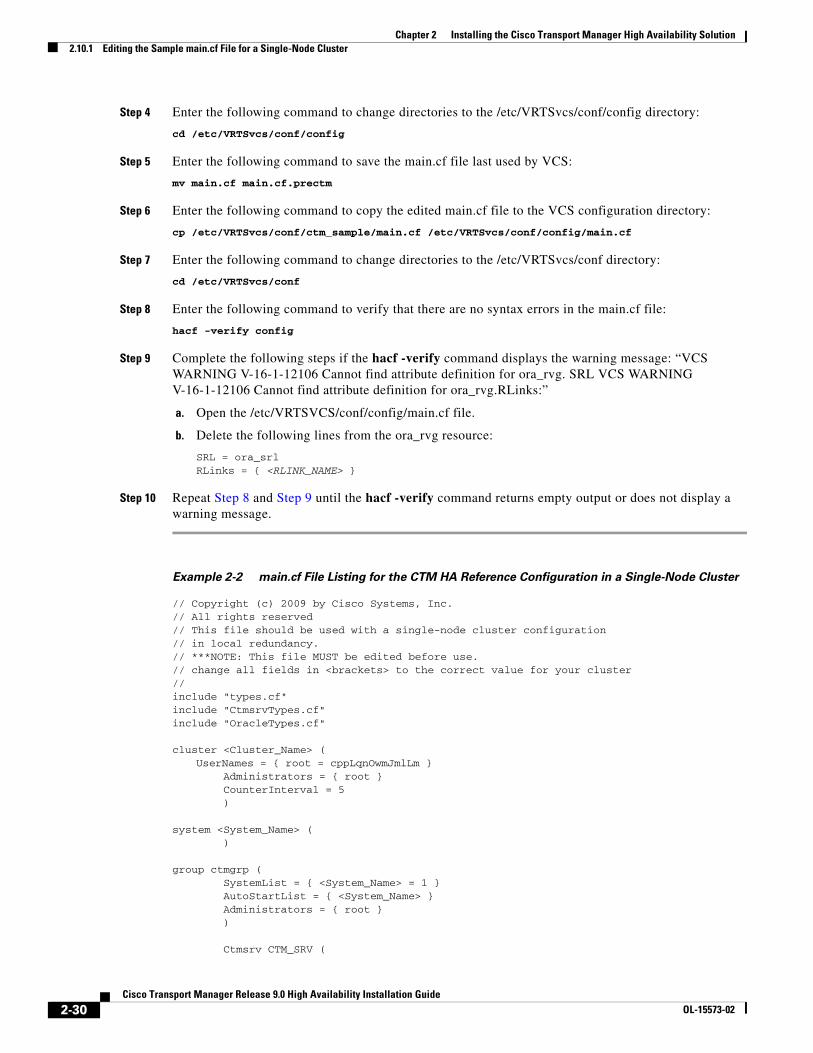
Step 4 Enter the following command to change directories to the /etc/VRTSvcs/conf/config directory:
cd /etc/VRTSvcs/conf/config
Step 5 Enter the following command to save the main.cf file last used by VCS:
mv main.cf main.cf.prectm
Step 6 Enter the following command to copy the edited main.cf file to the VCS configuration directory:
cp /etc/VRTSvcs/conf/ctm_sample/main.cf /etc/VRTSvcs/conf/config/main.cf
Step 7 Enter the following command to change directories to the /etc/VRTSvcs/conf directory:
cd /etc/VRTSvcs/conf
Step 8 Enter the following command to verify that there are no syntax errors in the main.cf file:
hacf -verify config
Step 9 Complete the following steps if the hacf -verify command displays the warning message: “VCS WARNING V-16-1-12106 Cannot find attribute definition for ora_rvg. SRL VCS WARNING V-16-1-12106 Cannot find attribute definition for ora_rvg.RLinks:”
a. Open the /etc/VRTSVCS/conf/config/main.cf file.
b. Delete the following lines from the ora_rvg resource:
SRL = ora_srlRLinks = { <RLINK_NAME> }
Step 10 Repeat Step 8 and Step 9 until the hacf -verify command returns empty output or does not display a warning message.
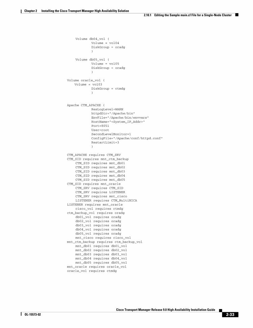
Example 2-2 main.cf File Listing for the CTM HA Reference Configuration in a Single-Node Cluster
// Copyright (c) 2009 by Cisco Systems, Inc.// All rights reserved// This file should be used with a single-node cluster configuration// in local redundancy.// ***NOTE: This file MUST be edited before use. // change all fields in <brackets> to the correct value for your cluster//include "types.cf"include "CtmsrvTypes.cf"include "OracleTypes.cf" cluster <Cluster_Name> (
UserNames = { root = cppLqnOwmJmlLm } Administrators = { root } CounterInterval = 5 ) system <System_Name> ( ) group ctmgrp ( SystemList = { <System_Name> = 1 } AutoStartList = { <System_Name> } Administrators = { root } ) Ctmsrv CTM_SRV (
2-30Cisco Transport Manager Release 9.0 High Availability Installation Guide
OL-15573-02
Chapter 2 Installing the Cisco Transport Manager High Availability Solution2.10.1 Editing the Sample main.cf File for a Single-Node Cluster
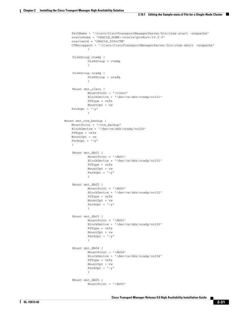
PathName = "/cisco/CiscoTransportManagerServer/bin/ctms-start -noapache"oraclehome = "ORACLE_HOME=/oracle/product/10.2.0"oraclesid = "ORACLE_SID=CTM"CTMstoppath = "/cisco/CiscoTransportManagerServer/bin/ctms-abort -noapache"
) DiskGroup ctmdg ( DiskGroup = ctmdg ) DiskGroup oradg ( DiskGroup = oradg ) Mount mnt_cisco ( MountPoint = "/cisco" BlockDevice = "/dev/vx/dsk/ctmdg/vol01" FSType = vxfs MountOpt = rw
FsckOpt = "-y" )
Mount mnt_ctm_backup (MountPoint = "/ctm_backup"BlockDevice = "/dev/vx/dsk/oradg/vol06"FSType = vxfsMountOpt = rwFsckOpt = "-y")
Mount mnt_db01 ( MountPoint = "/db01" BlockDevice = "/dev/vx/dsk/oradg/vol01" FSType = vxfs MountOpt = rw FsckOpt = "-y" ) Mount mnt_db02 ( MountPoint = "/db02" BlockDevice = "/dev/vx/dsk/oradg/vol02" FSType = vxfs MountOpt = rw FsckOpt = "-y" ) Mount mnt_db03 ( MountPoint = "/db03" BlockDevice = "/dev/vx/dsk/oradg/vol03" FSType = vxfs MountOpt = rw FsckOpt = "-y" ) Mount mnt_db04 ( MountPoint = "/db04" BlockDevice = "/dev/vx/dsk/oradg/vol04" FSType = vxfs MountOpt = rw FsckOpt = "-y" ) Mount mnt_db05 ( MountPoint = "/db05"
2-31Cisco Transport Manager Release 9.0 High Availability Installation Guide
OL-15573-02
Chapter 2 Installing the Cisco Transport Manager High Availability Solution2.10.1 Editing the Sample main.cf File for a Single-Node Cluster
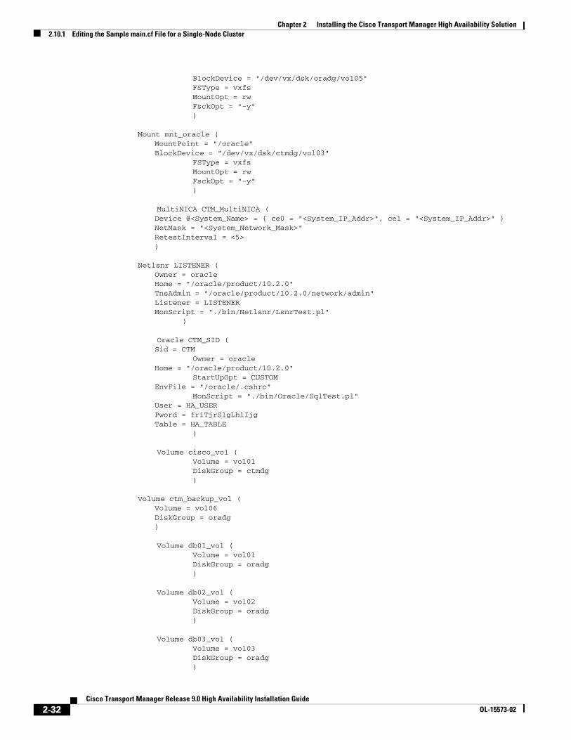
BlockDevice = "/dev/vx/dsk/oradg/vol05" FSType = vxfs MountOpt = rw FsckOpt = "-y" )
Mount mnt_oracle (MountPoint = "/oracle"BlockDevice = "/dev/vx/dsk/ctmdg/vol03"
FSType = vxfs MountOpt = rw FsckOpt = "-y" ) MultiNICA CTM_MultiNICA (
Device @<System_Name> = { ce0 = "<System_IP_Addr>", ce1 = "<System_IP_Addr>" }NetMask = "<System_Network_Mask>"RetestInterval = <5>)
Netlsnr LISTENER (Owner = oracleHome = "/oracle/product/10.2.0"TnsAdmin = "/oracle/product/10.2.0/network/admin"Listener = LISTENERMonScript = "./bin/Netlsnr/LsnrTest.pl"
) Oracle CTM_SID (
Sid = CTM Owner = oracle
Home = "/oracle/product/10.2.0" StartUpOpt = CUSTOM
EnvFile = "/oracle/.cshrc" MonScript = "./bin/Oracle/SqlTest.pl"
User = HA_USERPword = friTjrSlgLhlIjgTable = HA_TABLE
) Volume cisco_vol ( Volume = vol01 DiskGroup = ctmdg )
Volume ctm_backup_vol (Volume = vol06DiskGroup = oradg)
Volume db01_vol ( Volume = vol01 DiskGroup = oradg ) Volume db02_vol ( Volume = vol02 DiskGroup = oradg ) Volume db03_vol ( Volume = vol03 DiskGroup = oradg )
2-32Cisco Transport Manager Release 9.0 High Availability Installation Guide
OL-15573-02
Chapter 2 Installing the Cisco Transport Manager High Availability Solution2.10.1 Editing the Sample main.cf File for a Single-Node Cluster
Volume db04_vol ( Volume = vol04 DiskGroup = oradg ) Volume db05_vol ( Volume = vol05 DiskGroup = oradg )
Volume oracle_vol (Volume = vol03
DiskGroup = ctmdg )
Apache CTM_APACHE ( ResLogLevel=WARN httpdDir="/Apache/bin" EnvFile="/Apache/bin/envvars" HostName="<System_IP_Addr>" Port=8051 User=root SecondLevelMonitor=1 ConfigFile="/Apache/conf/httpd.conf" RestartLimit=3 )
CTM_APACHE requires CTM_SRVCTM_SID requires mnt_ctm_backup
CTM_SID requires mnt_db01 CTM_SID requires mnt_db02 CTM_SID requires mnt_db03 CTM_SID requires mnt_db04 CTM_SID requires mnt_db05
CTM_SID requires mnt_oracle CTM_SRV requires CTM_SID CTM_SRV requires LISTENER CTM_SRV requires mnt_cisco LISTENER requires CTM_MultiNICA
LISTENER requires mnt_oracle cisco_vol requires ctmdg
ctm_backup_vol requires oradg db01_vol requires oradg db02_vol requires oradg db03_vol requires oradg db04_vol requires oradg db05_vol requires oradg mnt_cisco requires cisco_vol
mnt_ctm_backup requires ctm_backup_vol mnt_db01 requires db01_vol mnt_db02 requires db02_vol mnt_db03 requires db03_vol mnt_db04 requires db04_vol mnt_db05 requires db05_vol
mnt_oracle requires oracle_voloracle_vol requires ctmdg
2-33Cisco Transport Manager Release 9.0 High Availability Installation Guide
OL-15573-02
Chapter 2 Installing the Cisco Transport Manager High Availability Solution2.10.2 Editing the Sample main.cf File for a Dual-Node Cluster
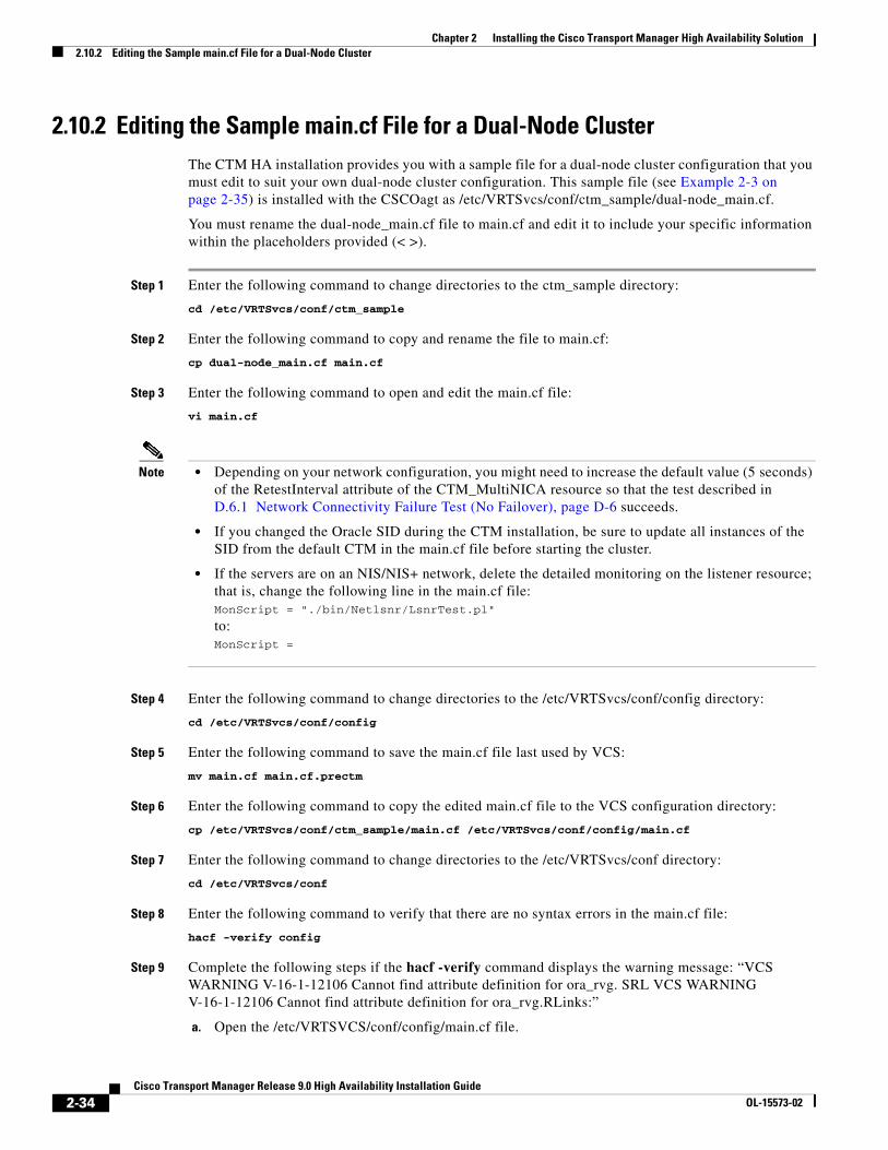
2.10.2 Editing the Sample main.cf File for a Dual-Node ClusterThe CTM HA installation provides you with a sample file for a dual-node cluster configuration that you must edit to suit your own dual-node cluster configuration. This sample file (see Example 2-3 on page 2-35) is installed with the CSCOagt as /etc/VRTSvcs/conf/ctm_sample/dual-node_main.cf.
You must rename the dual-node_main.cf file to main.cf and edit it to include your specific information within the placeholders provided (< >).
Step 1 Enter the following command to change directories to the ctm_sample directory:
cd /etc/VRTSvcs/conf/ctm_sample
Step 2 Enter the following command to copy and rename the file to main.cf:
cp dual-node_main.cf main.cf
Step 3 Enter the following command to open and edit the main.cf file:
vi main.cf
Note • Depending on your network configuration, you might need to increase the default value (5 seconds) of the RetestInterval attribute of the CTM_MultiNICA resource so that the test described in D.6.1 Network Connectivity Failure Test (No Failover), page D-6 succeeds.
• If you changed the Oracle SID during the CTM installation, be sure to update all instances of the SID from the default CTM in the main.cf file before starting the cluster.
• If the servers are on an NIS/NIS+ network, delete the detailed monitoring on the listener resource; that is, change the following line in the main.cf file: MonScript = "./bin/Netlsnr/LsnrTest.pl"
to:MonScript =
Step 4 Enter the following command to change directories to the /etc/VRTSvcs/conf/config directory:
cd /etc/VRTSvcs/conf/config
Step 5 Enter the following command to save the main.cf file last used by VCS:
mv main.cf main.cf.prectm
Step 6 Enter the following command to copy the edited main.cf file to the VCS configuration directory:
cp /etc/VRTSvcs/conf/ctm_sample/main.cf /etc/VRTSvcs/conf/config/main.cf
Step 7 Enter the following command to change directories to the /etc/VRTSvcs/conf directory:
cd /etc/VRTSvcs/conf
Step 8 Enter the following command to verify that there are no syntax errors in the main.cf file:
hacf -verify config
Step 9 Complete the following steps if the hacf -verify command displays the warning message: “VCS WARNING V-16-1-12106 Cannot find attribute definition for ora_rvg. SRL VCS WARNING V-16-1-12106 Cannot find attribute definition for ora_rvg.RLinks:”
a. Open the /etc/VRTSVCS/conf/config/main.cf file.
2-34Cisco Transport Manager Release 9.0 High Availability Installation Guide
OL-15573-02
Chapter 2 Installing the Cisco Transport Manager High Availability Solution2.10.2 Editing the Sample main.cf File for a Dual-Node Cluster
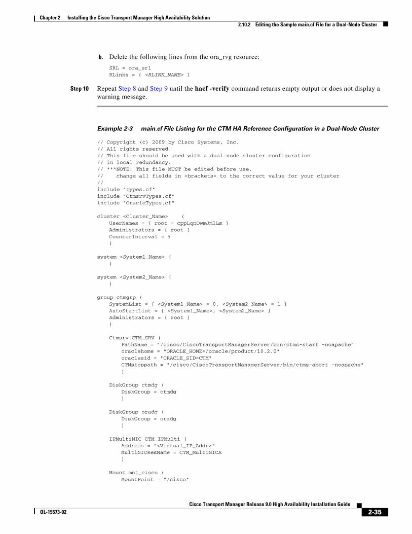
b. Delete the following lines from the ora_rvg resource:
SRL = ora_srlRLinks = { <RLINK_NAME> }
Step 10 Repeat Step 8 and Step 9 until the hacf -verify command returns empty output or does not display a warning message.
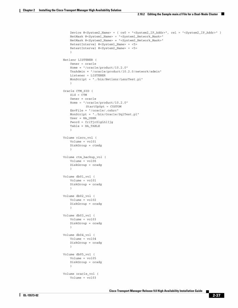
Example 2-3 main.cf File Listing for the CTM HA Reference Configuration in a Dual-Node Cluster
// Copyright (c) 2009 by Cisco Systems, Inc.// All rights reserved// This file should be used with a dual-node cluster configuration// in local redundancy. // ***NOTE: This file MUST be edited before use.// change all fields in <brackets> to the correct value for your cluster//include "types.cf"include "CtmsrvTypes.cf"include "OracleTypes.cf"
cluster <Cluster_Name> (UserNames = { root = cppLqnOwmJmlLm }Administrators = { root }CounterInterval = 5)
system <System1_Name> ()
system <System2_Name> ()
group ctmgrp (SystemList = { <System1_Name> = 0, <System2_Name> = 1 }AutoStartList = { <System1_Name>, <System2_Name> }Administrators = { root })
Ctmsrv CTM_SRV (PathName = "/cisco/CiscoTransportManagerServer/bin/ctms-start -noapache"oraclehome = "ORACLE_HOME=/oracle/product/10.2.0"oraclesid = "ORACLE_SID=CTM"CTMstoppath = "/cisco/CiscoTransportManagerServer/bin/ctms-abort -noapache")
DiskGroup ctmdg (DiskGroup = ctmdg)
DiskGroup oradg (DiskGroup = oradg)
IPMultiNIC CTM_IPMulti (Address = "<Virtual_IP_Addr>"MultiNICResName = CTM_MultiNICA)
Mount mnt_cisco (MountPoint = "/cisco"
2-35Cisco Transport Manager Release 9.0 High Availability Installation Guide
OL-15573-02
Chapter 2 Installing the Cisco Transport Manager High Availability Solution2.10.2 Editing the Sample main.cf File for a Dual-Node Cluster
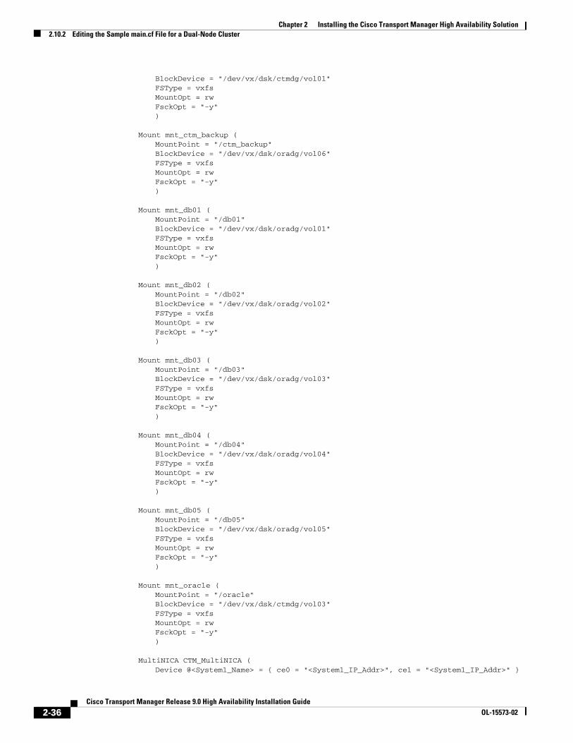
BlockDevice = "/dev/vx/dsk/ctmdg/vol01"FSType = vxfsMountOpt = rwFsckOpt = "-y")
Mount mnt_ctm_backup (MountPoint = "/ctm_backup"BlockDevice = "/dev/vx/dsk/oradg/vol06"FSType = vxfsMountOpt = rwFsckOpt = "-y")
Mount mnt_db01 (MountPoint = "/db01"BlockDevice = "/dev/vx/dsk/oradg/vol01"FSType = vxfsMountOpt = rwFsckOpt = "-y")
Mount mnt_db02 (MountPoint = "/db02"BlockDevice = "/dev/vx/dsk/oradg/vol02"FSType = vxfsMountOpt = rwFsckOpt = "-y")
Mount mnt_db03 (MountPoint = "/db03"BlockDevice = "/dev/vx/dsk/oradg/vol03"FSType = vxfsMountOpt = rwFsckOpt = "-y")
Mount mnt_db04 (MountPoint = "/db04"BlockDevice = "/dev/vx/dsk/oradg/vol04"FSType = vxfsMountOpt = rwFsckOpt = "-y")
Mount mnt_db05 (MountPoint = "/db05"BlockDevice = "/dev/vx/dsk/oradg/vol05"FSType = vxfsMountOpt = rwFsckOpt = "-y")
Mount mnt_oracle (MountPoint = "/oracle"BlockDevice = "/dev/vx/dsk/ctmdg/vol03"FSType = vxfsMountOpt = rwFsckOpt = "-y")
MultiNICA CTM_MultiNICA (Device @<System1_Name> = { ce0 = "<System1_IP_Addr>", ce1 = "<System1_IP_Addr>" }
2-36Cisco Transport Manager Release 9.0 High Availability Installation Guide
OL-15573-02
Chapter 2 Installing the Cisco Transport Manager High Availability Solution2.10.2 Editing the Sample main.cf File for a Dual-Node Cluster
Device @<System2_Name> = { ce0 = "<System2_IP_Addr>", ce1 = "<System2_IP_Addr>" }NetMask @<System1_Name> = "<System1_Network_Mask>"NetMask @<System2_Name> = "<System2_Network_Mask>"RetestInterval @<System1_Name> = <5>RetestInterval @<System2_Name> = <5>)
Netlsnr LISTENER (Owner = oracleHome = "/oracle/product/10.2.0"TnsAdmin = "/oracle/product/10.2.0/network/admin"Listener = LISTENERMonScript = "./bin/Netlsnr/LsnrTest.pl")
Oracle CTM_SID (Sid = CTMOwner = oracleHome = "/oracle/product/10.2.0"
StartUpOpt = CUSTOMEnvFile = "/oracle/.cshrc"MonScript = "./bin/Oracle/SqlTest.pl"User = HA_USERPword = friTjrSlgLhlIjgTable = HA_TABLE)
Volume cisco_vol (Volume = vol01DiskGroup = ctmdg)
Volume ctm_backup_vol (Volume = vol06DiskGroup = oradg)
Volume db01_vol (Volume = vol01DiskGroup = oradg)
Volume db02_vol (Volume = vol02DiskGroup = oradg)
Volume db03_vol (Volume = vol03DiskGroup = oradg)
Volume db04_vol (Volume = vol04DiskGroup = oradg)
Volume db05_vol (Volume = vol05DiskGroup = oradg)
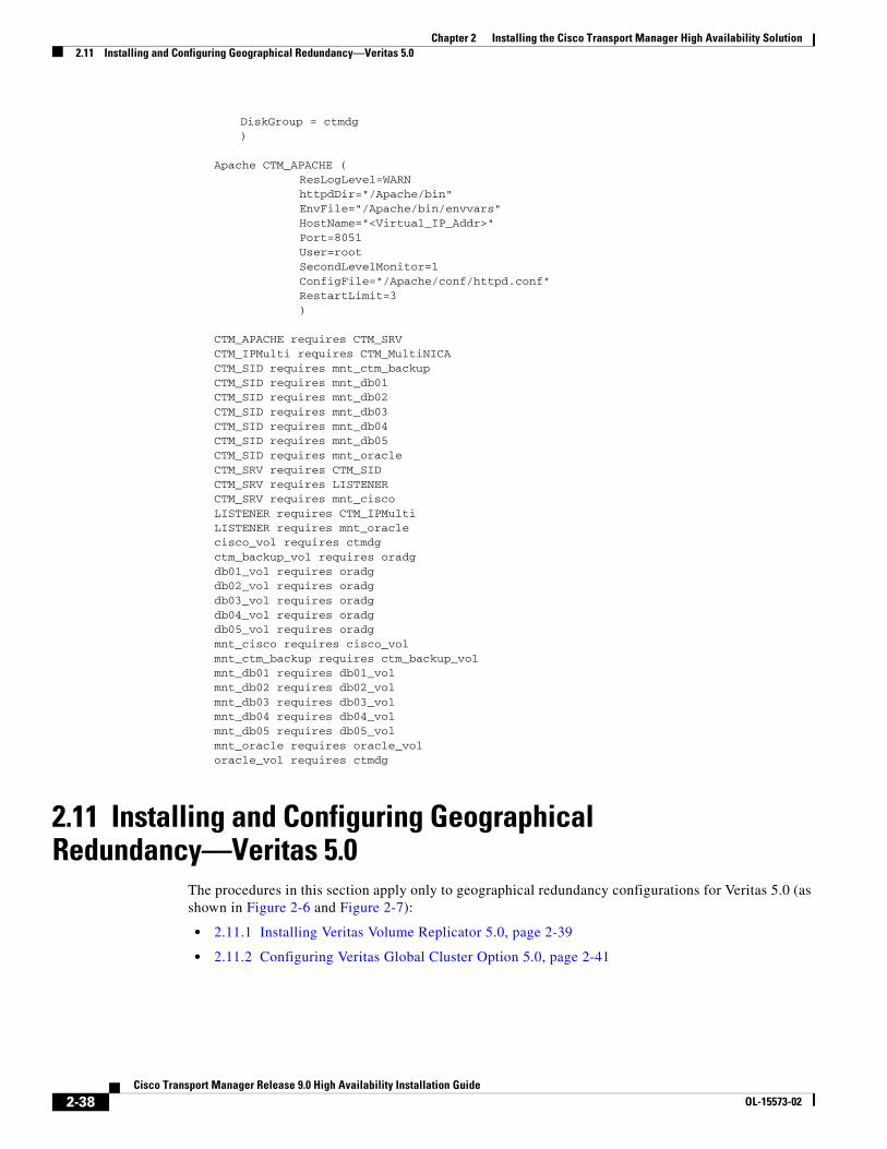
Volume oracle_vol (Volume = vol03
2-37Cisco Transport Manager Release 9.0 High Availability Installation Guide
OL-15573-02
Chapter 2 Installing the Cisco Transport Manager High Availability Solution2.11 Installing and Configuring Geographical Redundancy—Veritas 5.0
DiskGroup = ctmdg)
Apache CTM_APACHE ( ResLogLevel=WARN httpdDir="/Apache/bin" EnvFile="/Apache/bin/envvars" HostName="<Virtual_IP_Addr>" Port=8051 User=root SecondLevelMonitor=1 ConfigFile="/Apache/conf/httpd.conf" RestartLimit=3 )
CTM_APACHE requires CTM_SRVCTM_IPMulti requires CTM_MultiNICACTM_SID requires mnt_ctm_backupCTM_SID requires mnt_db01CTM_SID requires mnt_db02CTM_SID requires mnt_db03CTM_SID requires mnt_db04CTM_SID requires mnt_db05CTM_SID requires mnt_oracleCTM_SRV requires CTM_SIDCTM_SRV requires LISTENERCTM_SRV requires mnt_ciscoLISTENER requires CTM_IPMultiLISTENER requires mnt_oraclecisco_vol requires ctmdgctm_backup_vol requires oradgdb01_vol requires oradgdb02_vol requires oradgdb03_vol requires oradgdb04_vol requires oradgdb05_vol requires oradgmnt_cisco requires cisco_volmnt_ctm_backup requires ctm_backup_volmnt_db01 requires db01_volmnt_db02 requires db02_volmnt_db03 requires db03_volmnt_db04 requires db04_volmnt_db05 requires db05_volmnt_oracle requires oracle_voloracle_vol requires ctmdg
2.11 Installing and Configuring Geographical Redundancy—Veritas 5.0
The procedures in this section apply only to geographical redundancy configurations for Veritas 5.0 (as shown in Figure 2-6 and Figure 2-7):
• 2.11.1 Installing Veritas Volume Replicator 5.0, page 2-39
• 2.11.2 Configuring Veritas Global Cluster Option 5.0, page 2-41
2-38Cisco Transport Manager Release 9.0 High Availability Installation Guide
OL-15573-02
Chapter 2 Installing the Cisco Transport Manager High Availability Solution2.11.1 Installing Veritas Volume Replicator 5.0
2.11.1 Installing Veritas Volume Replicator 5.0This section provides supporting information to assist you with the VVR installation. Use this information with Symantec’s Veritas documentation; specifically, the Veritas Volume Replicator 5.0 Configuration Notes and the Veritas Volume Replicator 5.0 Installation Guide.
To install the VVR packages, complete the following steps:
Step 1 As the root user, perform the following substeps on the primary server at each site:
a. Insert the Veritas Volume Replicator 5.0 CD and enter the following commands:
cd /cdrom/cdrom0/volume_replicator./installvvr/sbin/vxlicinst
b. Enter the hostnames of all systems and continue.
c. To allow NE configuration backups to be replicated, enter the following commands to move the /cisco/CiscoTransportManagerServer/admin directory to /db01 and create a link to it:
mv /cisco/CiscoTransportManagerServer/admin /db01ln -s /db01/admin /cisco/CiscoTransportManagerServer/admin
d. Set the VVR tunable parameters. The Veritas Volume Replicator 5.0 Planning and Tuning Guide (Solaris) describes the parameters and how to change them. See http://ftp.support.veritas.com/pub/support/products/Volume_Replicator/283921.pdf.
Step 2 Reboot each server at both sites to have the settings take effect (if necessary).
Step 3 Enter the following command to verify that vradmind is running on each server:
ps -ef | grep vradmin
The following sample lists a typical output:
root 624 1 0 Aug 07 ? 22:37 /usr/sbin/vradmindroot 9083 7160 0 18:29:37 pts/4 0:00 grep vradmin
Step 4 Enter the following command to take all VCS service groups offline on the primary server:
hagrp -offline ctmgrp -any
Step 5 Enter the following commands to freeze ctmgrp on the primary server in both clusters:
haconf -makerwhagrp -freeze ctmgrp -persistenthaconf -dump -makero
Step 6 Enter the following commands to import oradg and start all of the volumes (vol01, vol02, vol03, vol04, and vol05) on the active server at both sites (that is, on the primary server in both clusters):
/usr/sbin/vxdg import oradg/usr/sbin/vxvol -g oradg startall
Caution Do not mount the volumes (vol01, vol02, vol03, vol04, and vol05).
Step 7 Enter the following command to create the Storage Replicator Link (SRL) volume in oradg for replication on the primary server at both sites. (In this example the SRL is set to 30 GB; use an SRL size that is appropriate.)
2-39Cisco Transport Manager Release 9.0 High Availability Installation Guide
OL-15573-02
Chapter 2 Installing the Cisco Transport Manager High Availability Solution2.11.1 Installing Veritas Volume Replicator 5.0
Note To determine the appropriate SRL size, see the Veritas Volume Replicator Configuration Notes.
vxassist -g oradg make ora_srl 30g nmirror=2 oradg01 oradg02
Step 8 Add a plus sign (+) to the /etc/vx/vras/.rdg file on all systems to allow volume synchronization.
Step 9 (For a dual-node cluster only, as shown in Figure 2-7) Enter the following command to plumb the virtual interface on the primary servers:
ifconfig qfe1:1 plumb
Step 10 (For a dual-node cluster only, as shown in Figure 2-7) Enter the following command to configure the virtual interface on the primary servers:
ifconfig qfe1:1 <virtual_IP_address> netmask <netmask> up
Step 11 Enter the following command to create the primary Replicated Volume Group (RVG) on the primary server of the primary cluster only:
vradmin -g oradg createpri ora_rvg vol01,vol02,vol03,vol04,vol05 ora_srl
Note • Replicated data volumes and the SRL cannot have associated Dirty Region Logs (DRLs). If you have DRLs, you will receive the following error message:vxvm:vxvol: ERROR: associating volume vol05 with ora_rvg: Replicated volume may not
have a drl
If you receive this message, enter the following command to remove the DRLs from the respective volumes:vxassist -g oradg remove log <volume_name>
• Data Change Map (DCM) logs must be associated with data volumes. Enter the following command to attach a DCM log:vxassist -g oradg addlog <volume_name> logtype=dcm
If oradg contains only a single disk, DCM logs must be mirrored by default. Add the nlog=1 option to the preceding command, as follows:vxassist -g oradg addlog <volume_name> logtype=dcm nlog=1
Step 12 Enter the following command on the primary server of the primary cluster to create the secondary RVG and RLINK:
Caution Before entering the following command, verify that on the secondary cluster the volumes (vol01, vol02, vol03, vol04, and vol05) are not mounted, and the virtual IP address is up (active) on the primary server of the secondary cluster.
vradmin -g oradg addsec ora_rvg <primary_replication_IP_address> <secondary_replication_IP_address> prlink=ora_<secondary_site_name>_rlk srlink=ora_<primary_site_name>_rlk
Step 13 Enter the following commands to verify that replication is configured:
vradmin -l printrvgvxprint -Pl
2-40Cisco Transport Manager Release 9.0 High Availability Installation Guide
OL-15573-02
Chapter 2 Installing the Cisco Transport Manager High Availability Solution2.11.2 Configuring Veritas Global Cluster Option 5.0
Step 14 Enter the following command at the primary site to synchronize and attach the RVG and RLINK:
vradmin -g oradg -a startrep ora_rvg <secondary_replication_IP_address>
Step 15 Verify that the first synchronization is complete (up to date) by entering the following command on the primary server of the primary cluster:
vxrlink -g oradg -r ora_rvg status ora_<secondary_site_name>_rlk
The following sample lists a typical output, which states that the synchronization is up to date:
Wed Aug 23 13:50:14 EEST 2008VxVM VVR vxrlink INFO V-5-1-4467 Rlink ora_<secondary_site_name>_rlk is up to date
Step 16 Verify that replication is working correctly and that you can migrate the RVG to and from the secondary cluster by entering the following command to migrate the RVG to the secondary cluster:
vradmin -g oradg migrate ora_rvg <secondary_replication_IP_address>
2.11.2 Configuring Veritas Global Cluster Option 5.0This section provides supporting information to assist you with the Veritas Global Cluster Option configuration. Use this information with Symantec’s Veritas documentation; specifically, section V of the Veritas Cluster Manager 5.0 User’s Guide at http://ftp.support.veritas.com/pub/support/products/ClusterServer_UNIX/275725.pdf.
The following prerequisites should be met before attempting to configure a CTM geographical redundancy installation:
• Each local cluster must have the complete CTM HA local redundancy configuration installed and working properly. The data replication and CTM should be running on the primary server of the primary cluster.
• Each local cluster must have IP connectivity to all other clusters.
• The VCS Global Cluster option license for each cluster must be installed.
• Clusters must be using the same VCS version.
• Cluster names must be unique within the global cluster environment.
• Cluster service groups must have the same name in each cluster.
See the Veritas Cluster Server 5.0 User Guide at http://ftp.support.veritas.com/pub/support/products/ClusterServer_UNIX/275725.pdf for more information.
Note This website is © 1998–2009, Symantec Corporation. All rights reserved.
This section explains how to modify your existing local cluster configuration to prepare the Global Cluster Option installation. The RVG, associated disk group, and associated IP address must be in an independent service group separate from the CTM application. Separating the groups allows the RVG to be online while the CTM group is offline at that site.
2-41Cisco Transport Manager Release 9.0 High Availability Installation Guide
OL-15573-02
Chapter 2 Installing the Cisco Transport Manager High Availability Solution2.11.2 Configuring Veritas Global Cluster Option 5.0
2.11.2.1 Configuring Veritas Global Cluster Option 5.0 for Single-Node Clusters
You must rename the single-node-pregcm_main.cf file to main.cf and edit it to include your specific information within the placeholders provided (< >). See 2.11.2.1.1 Sample main.cf File for a Single-Node Cluster in a Geographical Redundancy Configuration, page 2-46.
Note This section applies to single-node cluster configurations, as shown in Figure 2-6.
Step 1 Enter the following command to stop the VCS on all of the servers:
hastop -all -force
Note Complete Step 2 to Step 17 only on the primary server of the primary cluster.
Step 2 Enter the following command to change directories to the ctm_sample directory:
cd /etc/VRTSvcs/conf/ctm_sample
Step 3 Enter the following command to copy and rename the file to main.cf:
cp single-node-pregcm_main.cf main.cf
Step 4 Edit the file to include your specific information within the placeholders provided (< >). Enter the following command to open and edit the main.cf file:
vi main.cf
Note • Depending on your network configuration, you might need to increase the default value (5 seconds) of the RetestInterval attribute of the CTM_MultiNICA resource so that the test described in D.6.1 Network Connectivity Failure Test (No Failover), page D-6 succeeds.
• If you changed the Oracle SID during the CTM installation, be sure to update all instances of the SID from the default CTM in the main.cf file before starting the cluster.
• If the servers are on an NIS/NIS+ network, delete the detailed monitoring on the listener resource; that is, change the following line in the main.cf file: MonScript = "./bin/Netlsnr/LsnrTest.pl"
to:MonScript =
Step 5 Enter the following command to change directories to the /etc/VRTSvcs/conf/config directory:
cd /etc/VRTSvcs/conf/config
Step 6 Enter the following command to save the main.cf file last used by VCS:
mv main.cf main.cf.pregeoctm
Step 7 Enter the following command to copy the edited main.cf file to the VCS configuration directory:
cp /etc/VRTSvcs/conf/ctm_sample/main.cf /etc/VRTSvcs/conf/config/main.cf
Step 8 Enter the following command to change directories to the /etc/VRTSvcs/conf directory:
cd /etc/VRTSvcs/conf
2-42Cisco Transport Manager Release 9.0 High Availability Installation Guide
OL-15573-02
Chapter 2 Installing the Cisco Transport Manager High Availability Solution2.11.2 Configuring Veritas Global Cluster Option 5.0
Step 9 Enter the following command to verify that there are no syntax errors in the main.cf file:
hacf -verify config
Note See Appendix B, “Sample Diagrams of Global Cluster Option Installation and VCS Resource Views” for graphical representations of the single-node VCS service group and resource configurations.
Step 10 Complete the following steps if the hacf -verify command displays the warning message: “VCS WARNING V-16-1-12106 Cannot find attribute definition for ora_rvg. SRL VCS WARNING V-16-1-12106 Cannot find attribute definition for ora_rvg.RLinks:”
a. Open the /etc/VRTSVCS/conf/config/main.cf file.
b. Delete the following lines from the ora_rvg resource:
SRL = ora_srlRLinks = { <RLINK_NAME> }
Step 11 Repeat Step 9 and Step 10 until the hacf -verify command returns empty output or does not display a warning message.
Step 12 Enter the following command to start the Veritas Cluster Server:
/opt/VRTS/bin/hastart -onenode
Step 13 Enter the following command to start the GCO Configuration wizard:
/opt/VRTSvcs/bin/gcoconfig
Tip While running the GCO Configuration wizard, if you receive the error “e1000g1 is not a valid NIC name,” patch the system as described in Veritas hotfix 1397752. Contact Veritas support to obtain hotfix 1397752.
Step 14 Enter the following commands to remove the IP and NIC resources from the ClusterService service group:
/opt/VRTSvcs/bin/haconf -makerw /opt/VRTS/bin/hares -delete csgnic/opt/VRTS/bin/hares -delete gcoip/opt/VRTSvcs/bin/haconf -dump -makero
Step 15 Enter the following command to take the ctmgrp service group offline:
hagrp -offline ctmgrp -any
Step 16 Wait until the ctmgrp service group is offline, which might take a few minutes. Enter the following command to verify that the ctmgrp service group is offline:
hastatus -summary
The following sample lists a typical output when the ctmgrp service group is offline:
-- SYSTEM STATE-- System State Frozen
A ellesmera RUNNING 0
-- GROUP STATE-- Group System Probed AutoDisabled State
2-43Cisco Transport Manager Release 9.0 High Availability Installation Guide
OL-15573-02
Chapter 2 Installing the Cisco Transport Manager High Availability Solution2.11.2 Configuring Veritas Global Cluster Option 5.0
B ClusterService ellesmera Y N ONLINE B ctmgrp ellesmera Y N OFFLINE B ctmrvgrp ellesmera Y N ONLINE
Step 17 Enter the following commands to freeze ctmgrp:
haconf -makerwhagrp -freeze ctmgrp -persistenthaconf -dump -makero
Note Complete Step 18 to Step 32 only on the primary server of the secondary cluster.
Step 18 Enter the following command to change directories to the ctm_sample directory:
cd /etc/VRTSvcs/conf/ctm_sample
Step 19 Enter the following command to copy and rename the file to main.cf:
cp single-node-pregcm_main.cf main.cf
Step 20 Edit the file to include your specific information within the placeholders provided (< >). Enter the following command to open and edit the main.cf file:
vi main.cf
Note • Depending on your network configuration, you might need to increase the default value (5 seconds) of the RetestInterval attribute of the CTM_MultiNICA resource so that the test described in D.6.1 Network Connectivity Failure Test (No Failover), page D-6 succeeds.
• If you changed the Oracle SID during the CTM installation, be sure to update all instances of the SID from the default CTM in the main.cf file before starting the cluster.
• If the servers are on an NIS/NIS+ network, delete the detailed monitoring on the listener resource; that is, change the following line in the main.cf file: MonScript = "./bin/Netlsnr/LsnrTest.pl"
to:MonScript =
Step 21 Enter the following command to change directories to the /etc/VRTSvcs/conf/config directory:
cd /etc/VRTSvcs/conf/config
Step 22 Enter the following command to save the main.cf file last used by VCS:
mv main.cf main.cf.pregeoctm
Step 23 Enter the following command to copy the edited main.cf file to the VCS configuration directory:
cp /etc/VRTSvcs/conf/ctm_sample/main.cf /etc/VRTSvcs/conf/config/main.cf
Step 24 Enter the following command to change directories to the /etc/VRTSvcs/conf directory:
cd /etc/VRTSvcs/conf
Step 25 Enter the following command to verify that there are no syntax errors in the main.cf file:
hacf -verify config
2-44Cisco Transport Manager Release 9.0 High Availability Installation Guide
OL-15573-02
Chapter 2 Installing the Cisco Transport Manager High Availability Solution2.11.2 Configuring Veritas Global Cluster Option 5.0
Note See Appendix B, “Sample Diagrams of Global Cluster Option Installation and VCS Resource Views” for graphical representations of the single-node VCS service group and resource configurations.
Step 26 Complete the following steps if the hacf -verify command displays the warning message: “VCS WARNING V-16-1-12106 Cannot find attribute definition for ora_rvg. SRL VCS WARNING V-16-1-12106 Cannot find attribute definition for ora_rvg.RLinks:”
a. Open the /etc/VRTSVCS/conf/config/main.cf file.
b. Delete the following lines from the ora_rvg resource:
SRL = ora_srlRLinks = { <RLINK_NAME> }
Step 27 Repeat Step 25 and Step 26 until the hacf -verify command returns empty output or does not display a warning message.
Step 28 Enter the following command to start the Veritas Cluster Server:
/opt/VRTS/bin/hastart -onenode
Step 29 Enter the following command to start the GCO Configuration wizard. (Be sure to specify the virtual IP address for the global cluster.)
/opt/VRTSvcs/bin/gcoconfig
Tip While running the GCO Configuration wizard, if you receive the error “e1000g1 is not a valid NIC name,” patch the system as described in Veritas hotfix 1397752. Contact Veritas support to obtain hotfix 1397752.
Step 30 Enter the following commands to remove the IP and NIC resources from the ClusterService service group:
/opt/VRTSvcs/bin/haconf -makerw /opt/VRTS/bin/hares -delete csgnic/opt/VRTS/bin/hares -delete gcoip/opt/VRTSvcs/bin/haconf -dump -makero
Step 31 Enter the following command to take the ctmgrp service group offline:
hagrp -offline ctmgrp -any
Step 32 Wait until the ctmgrp service group is offline, which might take a few minutes. Enter the following command to verify that the ctmgrp service group is offline:
hastatus -summary
The following sample lists a typical output when the ctmgrp service group is offline:
-- SYSTEM STATE-- System State Frozen
A ellesmera RUNNING 0
-- GROUP STATE-- Group System Probed AutoDisabled State
B ClusterService ellesmera Y N ONLINE B ctmgrp ellesmera Y N OFFLINE B ctmrvgrp ellesmera Y N ONLINE
2-45Cisco Transport Manager Release 9.0 High Availability Installation Guide
OL-15573-02
Chapter 2 Installing the Cisco Transport Manager High Availability Solution2.11.2 Configuring Veritas Global Cluster Option 5.0
Note Complete Step 33 to Step 37 only on the primary server of the primary cluster.
Step 33 Enter the following commands to unfreeze the ctmgrp service group and bring it online:
haconf -makerwhagrp -unfreeze ctmgrp -persistenthaconf -dump -makerohagrp -online ctmgrp -any
Step 34 Use the Remote Cluster Configuration wizard in the VCS GUI (Edit > Add/Delete Remote Cluster) to add the remote cluster.
Tip To run the VCS GUI, enter the /opt/VRTS/bin/hagui command.
Step 35 Use the Global Group Configuration wizard in the VCS GUI (Edit > Configure Global Groups) to configure the CTM global service group. Use the Application group: ctmgrp parameter.
Caution Select Manual or Connected as the failover mode. Do not select the Auto failover mode option, because it could cause a split-brain condition or disconnect the network.
Step 36 Verify that the service group dependency for the ctmgrp and ctmrvgrp is online local hard.
Step 37 Verify the Global Cluster Option installation. For a sample graph view of a Global Cluster Option installation, see Figure B-1 on page B-2.
2.11.2.1.1 Sample main.cf File for a Single-Node Cluster in a Geographical Redundancy Configuration
The example that follows this procedure lists the main.cf file for a single-node configuration prior to the Global Cluster Option installation. This sample file is installed with the CSCOagt as /etc/VRTSvcs/conf/ctm_sample/single-node-pregcm_main.cf.
You must rename the file to main.cf and edit it to include your specific information. After you edit the main.cf file, complete the following steps:
Step 1 Enter the following command to verify that you have no syntax errors:
hacf -verify config
Step 2 Complete the following steps if the hacf -verify command displays the warning message: “VCS WARNING V-16-1-12106 Cannot find attribute definition for ora_rvg. SRL VCS WARNING V-16-1-12106 Cannot find attribute definition for ora_rvg.RLinks:”
a. Open the /etc/VRTSVCS/conf/config/main.cf file.
b. Delete the following lines from the ora_rvg resource:
SRL = ora_srlRLinks = { <RLINK_NAME> }
2-46Cisco Transport Manager Release 9.0 High Availability Installation Guide
OL-15573-02
Chapter 2 Installing the Cisco Transport Manager High Availability Solution2.11.2 Configuring Veritas Global Cluster Option 5.0
Step 3 Repeat Step 1 and Step 2 until the hacf -verify command returns empty output or does not display a warning message.
Note • If you changed the Oracle SID during the CTM installation, be sure to update all instances of the SID from the default CTM in the main.cf file before starting the cluster.
• If the servers are on an NIS/NIS+ network, delete the detailed monitoring on the listener resource; that is, change the following line in the main.cf file: MonScript = "./bin/Netlsnr/LsnrTest.pl"
to:MonScript =
Example 2-4 main.cf file Listing for the CTM HA Reference Configuration in a Single-Node Cluster in
a Geographical Redundancy Configuration
// Copyright (c) 2009 by Cisco Systems, Inc.// All rights reserved// This file should be used with a single-node cluster configuration// in geographical redundancy.//// ***NOTE: This file MUST be edited before use.// change all fields in <brackets> to the correct value for your cluster//include "types.cf"include "CtmsrvTypes.cf"include "OracleTypes.cf"include "VVRTypes.cf"
cluster <Cluster_Name> (UserNames = { root = cppLqnOwmJmlLm }Administrators = { root }CounterInterval = 5)
system <System_Name> ()
group ctmgrp ( SystemList = { <System_Name> = 1 } AutoStartList = { <System_Name> } Administrators = { root } )
Ctmsrv CTM_SRV ( PathName = "/cisco/CiscoTransportManagerServer/bin/ctms-start -noapache" oraclehome = "ORACLE_HOME=/oracle/product/10.2.0" oraclesid = "ORACLE_SID=CTM" CTMstoppath = "/cisco/CiscoTransportManagerServer/bin/ctms-abort -noapache" )
DiskGroup ctmdg (DiskGroup = ctmdg)
Mount mnt_cisco (
2-47Cisco Transport Manager Release 9.0 High Availability Installation Guide
OL-15573-02
Chapter 2 Installing the Cisco Transport Manager High Availability Solution2.11.2 Configuring Veritas Global Cluster Option 5.0
MountPoint = "/cisco"BlockDevice = "/dev/vx/dsk/ctmdg/vol01"FSType = vxfsMountOpt = rw
FsckOpt = "-y")
Mount mnt_ctm_backup ( MountPoint = "/ctm_backup" BlockDevice = "/dev/vx/dsk/oradg/vol06" FSType = vxfs MountOpt = rw FsckOpt = "-y" )
Mount mnt_db01 (MountPoint = "/db01"BlockDevice = "/dev/vx/dsk/oradg/vol01"FSType = vxfsMountOpt = rw
FsckOpt = "-y")
Mount mnt_db02 (MountPoint = "/db02"BlockDevice = "/dev/vx/dsk/oradg/vol02"FSType = vxfsMountOpt = rw
FsckOpt = "-y")
Mount mnt_db03 (MountPoint = "/db03"BlockDevice = "/dev/vx/dsk/oradg/vol03"FSType = vxfsMountOpt = rw
FsckOpt = "-y")
Mount mnt_db04 (MountPoint = "/db04"BlockDevice = "/dev/vx/dsk/oradg/vol04"FSType = vxfsMountOpt = rw
FsckOpt = "-y")
Mount mnt_db05 (MountPoint = "/db05"BlockDevice = "/dev/vx/dsk/oradg/vol05"FSType = vxfsMountOpt = rw
FsckOpt = "-y")
Mount mnt_oracle ( MountPoint = "/oracle" BlockDevice = "/dev/vx/dsk/ctmdg/vol03" FSType = vxfs MountOpt = rw FsckOpt = "-y" )
2-48Cisco Transport Manager Release 9.0 High Availability Installation Guide
OL-15573-02
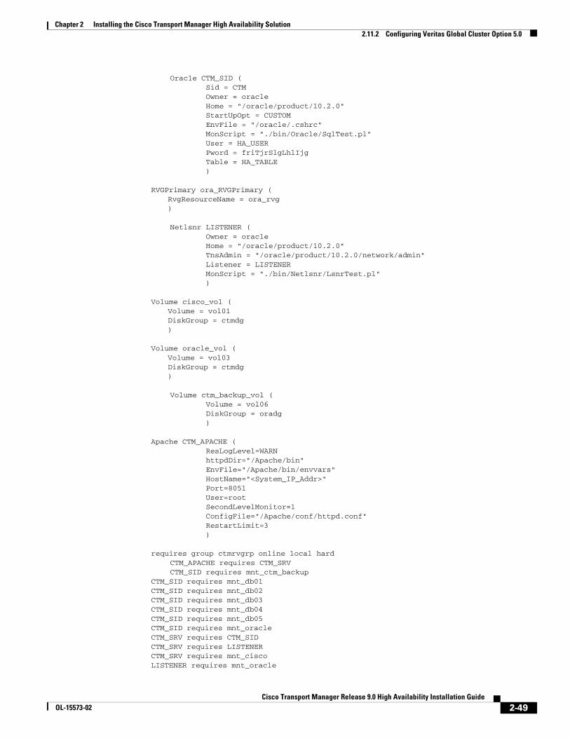
Chapter 2 Installing the Cisco Transport Manager High Availability Solution2.11.2 Configuring Veritas Global Cluster Option 5.0
Oracle CTM_SID ( Sid = CTM Owner = oracle Home = "/oracle/product/10.2.0" StartUpOpt = CUSTOM EnvFile = "/oracle/.cshrc" MonScript = "./bin/Oracle/SqlTest.pl" User = HA_USER Pword = friTjrSlgLhlIjg Table = HA_TABLE )
RVGPrimary ora_RVGPrimary (RvgResourceName = ora_rvg)
Netlsnr LISTENER ( Owner = oracle Home = "/oracle/product/10.2.0" TnsAdmin = "/oracle/product/10.2.0/network/admin" Listener = LISTENER MonScript = "./bin/Netlsnr/LsnrTest.pl" )
Volume cisco_vol (Volume = vol01DiskGroup = ctmdg)
Volume oracle_vol (Volume = vol03DiskGroup = ctmdg)
Volume ctm_backup_vol ( Volume = vol06 DiskGroup = oradg )
Apache CTM_APACHE ( ResLogLevel=WARN httpdDir="/Apache/bin" EnvFile="/Apache/bin/envvars" HostName="<System_IP_Addr>" Port=8051 User=root SecondLevelMonitor=1 ConfigFile="/Apache/conf/httpd.conf" RestartLimit=3 )
requires group ctmrvgrp online local hard CTM_APACHE requires CTM_SRV CTM_SID requires mnt_ctm_backup
CTM_SID requires mnt_db01CTM_SID requires mnt_db02CTM_SID requires mnt_db03CTM_SID requires mnt_db04CTM_SID requires mnt_db05CTM_SID requires mnt_oracleCTM_SRV requires CTM_SIDCTM_SRV requires LISTENERCTM_SRV requires mnt_ciscoLISTENER requires mnt_oracle
2-49Cisco Transport Manager Release 9.0 High Availability Installation Guide
OL-15573-02
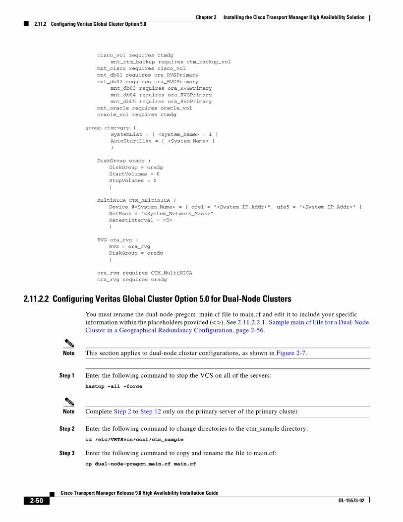
Chapter 2 Installing the Cisco Transport Manager High Availability Solution2.11.2 Configuring Veritas Global Cluster Option 5.0
cisco_vol requires ctmdg mnt_ctm_backup requires ctm_backup_vol
mnt_cisco requires cisco_volmnt_db01 requires ora_RVGPrimarymnt_db02 requires ora_RVGPrimary
mnt_db03 requires ora_RVGPrimary mnt_db04 requires ora_RVGPrimary mnt_db05 requires ora_RVGPrimary
mnt_oracle requires oracle_voloracle_vol requires ctmdg
group ctmrvgrp ( SystemList = { <System_Name> = 1 } AutoStartList = { <System_Name> } )
DiskGroup oradg (DiskGroup = oradgStartVolumes = 0StopVolumes = 0)
MultiNICA CTM_MultiNICA (Device @<System_Name> = { qfe1 = "<System_IP_Addr>", qfe5 = "<System_IP_Addr>" }NetMask = "<System_Network_Mask>"RetestInterval = <5>)
RVG ora_rvg (RVG = ora_rvgDiskGroup = oradg)
ora_rvg requires CTM_MultiNICAora_rvg requires oradg
2.11.2.2 Configuring Veritas Global Cluster Option 5.0 for Dual-Node Clusters
You must rename the dual-node-pregcm_main.cf file to main.cf and edit it to include your specific information within the placeholders provided (< >). See 2.11.2.2.1 Sample main.cf File for a Dual-Node Cluster in a Geographical Redundancy Configuration, page 2-56.
Note This section applies to dual-node cluster configurations, as shown in Figure 2-7.
Step 1 Enter the following command to stop the VCS on all of the servers:
hastop -all -force
Note Complete Step 2 to Step 12 only on the primary server of the primary cluster.
Step 2 Enter the following command to change directories to the ctm_sample directory:
cd /etc/VRTSvcs/conf/ctm_sample
Step 3 Enter the following command to copy and rename the file to main.cf:
cp dual-node-pregcm_main.cf main.cf
2-50Cisco Transport Manager Release 9.0 High Availability Installation Guide
OL-15573-02
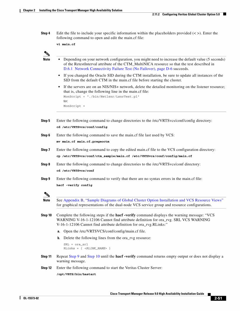
Chapter 2 Installing the Cisco Transport Manager High Availability Solution2.11.2 Configuring Veritas Global Cluster Option 5.0
Step 4 Edit the file to include your specific information within the placeholders provided (< >). Enter the following command to open and edit the main.cf file:
vi main.cf
Note • Depending on your network configuration, you might need to increase the default value (5 seconds) of the RetestInterval attribute of the CTM_MultiNICA resource so that the test described in D.6.1 Network Connectivity Failure Test (No Failover), page D-6 succeeds.
• If you changed the Oracle SID during the CTM installation, be sure to update all instances of the SID from the default CTM in the main.cf file before starting the cluster.
• If the servers are on an NIS/NIS+ network, delete the detailed monitoring on the listener resource; that is, change the following line in the main.cf file: MonScript = "./bin/Netlsnr/LsnrTest.pl"
to:MonScript =
Step 5 Enter the following command to change directories to the /etc/VRTSvcs/conf/config directory:
cd /etc/VRTSvcs/conf/config
Step 6 Enter the following command to save the main.cf file last used by VCS:
mv main.cf main.cf.pregeoctm
Step 7 Enter the following command to copy the edited main.cf file to the VCS configuration directory:
cp /etc/VRTSvcs/conf/ctm_sample/main.cf /etc/VRTSvcs/conf/config/main.cf
Step 8 Enter the following command to change directories to the /etc/VRTSvcs/conf directory:
cd /etc/VRTSvcs/conf
Step 9 Enter the following command to verify that there are no syntax errors in the main.cf file:
hacf -verify config
Note See Appendix B, “Sample Diagrams of Global Cluster Option Installation and VCS Resource Views” for graphical representations of the dual-node VCS service group and resource configurations.
Step 10 Complete the following steps if the hacf -verify command displays the warning message: “VCS WARNING V-16-1-12106 Cannot find attribute definition for ora_rvg. SRL VCS WARNING V-16-1-12106 Cannot find attribute definition for ora_rvg.RLinks:”
a. Open the /etc/VRTSVCS/conf/config/main.cf file.
b. Delete the following lines from the ora_rvg resource:
SRL = ora_srlRLinks = { <RLINK_NAME> }
Step 11 Repeat Step 9 and Step 10 until the hacf -verify command returns empty output or does not display a warning message.
Step 12 Enter the following command to start the Veritas Cluster Server:
/opt/VRTS/bin/hastart
2-51Cisco Transport Manager Release 9.0 High Availability Installation Guide
OL-15573-02
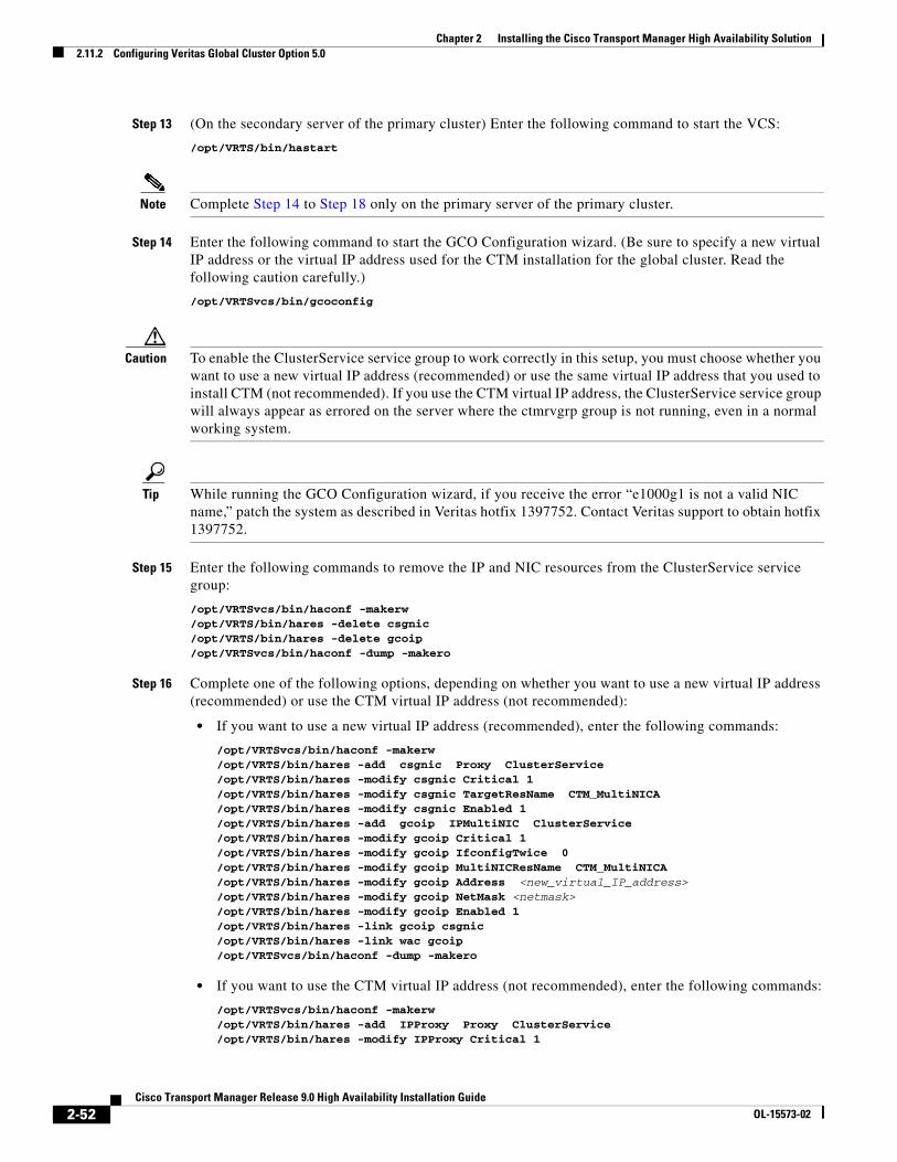
Chapter 2 Installing the Cisco Transport Manager High Availability Solution2.11.2 Configuring Veritas Global Cluster Option 5.0
Step 13 (On the secondary server of the primary cluster) Enter the following command to start the VCS:
/opt/VRTS/bin/hastart
Note Complete Step 14 to Step 18 only on the primary server of the primary cluster.
Step 14 Enter the following command to start the GCO Configuration wizard. (Be sure to specify a new virtual IP address or the virtual IP address used for the CTM installation for the global cluster. Read the following caution carefully.)
/opt/VRTSvcs/bin/gcoconfig
Caution To enable the ClusterService service group to work correctly in this setup, you must choose whether you want to use a new virtual IP address (recommended) or use the same virtual IP address that you used to install CTM (not recommended). If you use the CTM virtual IP address, the ClusterService service group will always appear as errored on the server where the ctmrvgrp group is not running, even in a normal working system.
Tip While running the GCO Configuration wizard, if you receive the error “e1000g1 is not a valid NIC name,” patch the system as described in Veritas hotfix 1397752. Contact Veritas support to obtain hotfix 1397752.
Step 15 Enter the following commands to remove the IP and NIC resources from the ClusterService service group:
/opt/VRTSvcs/bin/haconf -makerw /opt/VRTS/bin/hares -delete csgnic/opt/VRTS/bin/hares -delete gcoip/opt/VRTSvcs/bin/haconf -dump -makero
Step 16 Complete one of the following options, depending on whether you want to use a new virtual IP address (recommended) or use the CTM virtual IP address (not recommended):
• If you want to use a new virtual IP address (recommended), enter the following commands:
/opt/VRTSvcs/bin/haconf -makerw/opt/VRTS/bin/hares -add csgnic Proxy ClusterService/opt/VRTS/bin/hares -modify csgnic Critical 1/opt/VRTS/bin/hares -modify csgnic TargetResName CTM_MultiNICA /opt/VRTS/bin/hares -modify csgnic Enabled 1/opt/VRTS/bin/hares -add gcoip IPMultiNIC ClusterService/opt/VRTS/bin/hares -modify gcoip Critical 1/opt/VRTS/bin/hares -modify gcoip IfconfigTwice 0 /opt/VRTS/bin/hares -modify gcoip MultiNICResName CTM_MultiNICA /opt/VRTS/bin/hares -modify gcoip Address <new_virtual_IP_address> /opt/VRTS/bin/hares -modify gcoip NetMask <netmask> /opt/VRTS/bin/hares -modify gcoip Enabled 1/opt/VRTS/bin/hares -link gcoip csgnic/opt/VRTS/bin/hares -link wac gcoip/opt/VRTSvcs/bin/haconf -dump -makero
• If you want to use the CTM virtual IP address (not recommended), enter the following commands:
/opt/VRTSvcs/bin/haconf -makerw /opt/VRTS/bin/hares -add IPProxy Proxy ClusterService/opt/VRTS/bin/hares -modify IPProxy Critical 1
2-52Cisco Transport Manager Release 9.0 High Availability Installation Guide
OL-15573-02
Chapter 2 Installing the Cisco Transport Manager High Availability Solution2.11.2 Configuring Veritas Global Cluster Option 5.0
/opt/VRTS/bin/hares -modify IPProxy TargetResName CTM_IPMulti /opt/VRTS/bin/hares -modify IPProxy TargetSysName /opt/VRTS/bin/hares -modify IPProxy Enabled 1/opt/VRTS/bin/hares -link wac IPProxy/opt/VRTSvcs/bin/haconf -dump -makero
Step 17 Enter the following command to take the ctmgrp service group offline:
hagrp -offline ctmgrp -any
Step 18 Enter the following commands to freeze ctmgrp:
haconf -makerwhagrp -freeze ctmgrp -persistenthaconf -dump -makero
Note Complete Step 19 to Step 29 only on the primary server of the secondary cluster.
Step 19 Enter the following command to change directories to the ctm_sample directory:
cd /etc/VRTSvcs/conf/ctm_sample
Step 20 Enter the following command to copy and rename the file to main.cf:
cp dual-node-pregcm_main.cf main.cf
Step 21 Edit the file to include your specific information within the placeholders provided (< >). Enter the following command to open and edit the main.cf file:
vi main.cf
Note • Depending on your network configuration, you might need to increase the default value (5 seconds) of the RetestInterval attribute of the CTM_MultiNICA resource so that the test described in D.6.1 Network Connectivity Failure Test (No Failover), page D-6 succeeds.
• If you changed the Oracle SID during the CTM installation, be sure to update all instances of the SID from the default CTM in the main.cf file before starting the cluster.
• If the servers are on an NIS/NIS+ network, delete the detailed monitoring on the listener resource; that is, change the following line in the main.cf file: MonScript = "./bin/Netlsnr/LsnrTest.pl"
to:MonScript =
Step 22 Enter the following command to change directories to the /etc/VRTSvcs/conf/config directory:
cd /etc/VRTSvcs/conf/config
Step 23 Enter the following command to save the main.cf file last used by VCS:
mv main.cf main.cf.pregeoctm
Step 24 Enter the following command to copy the edited main.cf file to the VCS configuration directory:
cp /etc/VRTSvcs/conf/ctm_sample/main.cf /etc/VRTSvcs/conf/config/main.cf
Step 25 Enter the following command to change directories to the /etc/VRTSvcs/conf directory:
cd /etc/VRTSvcs/conf
2-53Cisco Transport Manager Release 9.0 High Availability Installation Guide
OL-15573-02
Chapter 2 Installing the Cisco Transport Manager High Availability Solution2.11.2 Configuring Veritas Global Cluster Option 5.0
Step 26 Enter the following command to verify that there are no syntax errors in the main.cf file:
hacf -verify config
Note See Appendix B, “Sample Diagrams of Global Cluster Option Installation and VCS Resource Views” for graphical representations of the dual-node VCS service group and resource configurations.
Step 27 Complete the following steps if the hacf -verify command displays the warning message: “VCS WARNING V-16-1-12106 Cannot find attribute definition for ora_rvg. SRL VCS WARNING V-16-1-12106 Cannot find attribute definition for ora_rvg.RLinks:”
a. Open the /etc/VRTSVCS/conf/config/main.cf file.
b. Delete the following lines from the ora_rvg resource:
SRL = ora_srlRLinks = { <RLINK_NAME> }
Step 28 Repeat Step 26 and Step 27 until the hacf -verify command returns empty output or does not display a warning message.
Step 29 Enter the following command to start the Veritas Cluster Server:
/opt/VRTS/bin/hastart -force
Step 30 (On the secondary server of the secondary cluster) Enter the following command to start the VCS:
/opt/VRTS/bin/hastart
Note Complete Step 31 to Step 35 only on the primary server of the secondary cluster.
Step 31 Enter the following command to start the GCO Configuration wizard:
Note Be sure to specify a new virtual IP address or the virtual IP address used for the CTM installation for the global cluster. Read the following caution carefully.
/opt/VRTSvcs/bin/gcoconfig
Caution To enable the ClusterService service group to work correctly in this setup, you must choose whether you want to use a new virtual IP address (recommended) or use the same virtual IP address that you used to install CTM (not recommended). If you use the CTM virtual IP address, the ClusterService service group will always appear as errored on the server where the ctmrvgrp group is not running, even in a normal working system.
Tip While running the GCO Configuration wizard, if you receive the error “e1000g1 is not a valid NIC name,” patch the system as described in Veritas hotfix 1397752. Contact Veritas support to obtain hotfix 1397752.
Step 32 Enter the following commands to remove the IP and NIC resources from the ClusterService service group:
2-54Cisco Transport Manager Release 9.0 High Availability Installation Guide
OL-15573-02
Chapter 2 Installing the Cisco Transport Manager High Availability Solution2.11.2 Configuring Veritas Global Cluster Option 5.0
/opt/VRTSvcs/bin/haconf -makerw /opt/VRTS/bin/hares -delete csgnic/opt/VRTS/bin/hares -delete gcoip/opt/VRTSvcs/bin/haconf -dump -makero
Step 33 Complete one of the following options, depending on whether you want to use a new virtual IP address (recommended) or use the CTM virtual IP address (not recommended):
• If you want to use a new virtual IP address (recommended), enter the following commands:
/opt/VRTSvcs/bin/haconf -makerw/opt/VRTS/bin/hares -add csgnic Proxy ClusterService/opt/VRTS/bin/hares -modify csgnic Critical 1/opt/VRTS/bin/hares -modify csgnic TargetResName CTM_MultiNICA /opt/VRTS/bin/hares -modify csgnic Enabled 1/opt/VRTS/bin/hares -add gcoip IPMultiNIC ClusterService/opt/VRTS/bin/hares -modify gcoip Critical 1/opt/VRTS/bin/hares -modify gcoip IfconfigTwice 0 /opt/VRTS/bin/hares -modify gcoip MultiNICResName CTM_MultiNICA /opt/VRTS/bin/hares -modify gcoip Address <new_virtual_IP_address> /opt/VRTS/bin/hares -modify gcoip NetMask <netmask> /opt/VRTS/bin/hares -modify gcoip Enabled 1/opt/VRTS/bin/hares -link gcoip csgnic/opt/VRTS/bin/hares -link wac gcoip/opt/VRTSvcs/bin/haconf -dump -makero
• If you want to use the CTM virtual IP address (not recommended), enter the following commands:
/opt/VRTSvcs/bin/haconf -makerw /opt/VRTS/bin/hares -add IPProxy Proxy ClusterService/opt/VRTS/bin/hares -modify IPProxy Critical 1/opt/VRTS/bin/hares -modify IPProxy TargetResName CTM_IPMulti /opt/VRTS/bin/hares -modify IPProxy TargetSysName /opt/VRTS/bin/hares -modify IPProxy Enabled 1/opt/VRTS/bin/hares -link wac IPProxy/opt/VRTSvcs/bin/haconf -dump -makero
Step 34 Enter the following command to take the ctmgrp service group offline:
hagrp -offline ctmgrp -any
Step 35 Enter the following commands to freeze the ctmgrp service group:
haconf -makerwhagrp -freeze ctmgrp -persistenthaconf -dump -makero
Step 36 (On the primary server of the primary cluster) Enter the following commands to unfreeze the ctmgrp service group and bring it online:
haconf -makerwhagrp -unfreeze ctmgrp -persistenthaconf -dump -makerohagrp -online ctmgrp -any
Step 37 (On the primary server of the secondary cluster) Enter the following commands to unfreeze the ctmgrp service group:
haconf -makerwhagrp -unfreeze ctmgrp -persistenthaconf -dump -makero
Note Complete Step 38 to Step 41 only on the primary server of the primary cluster.
2-55Cisco Transport Manager Release 9.0 High Availability Installation Guide
OL-15573-02
Chapter 2 Installing the Cisco Transport Manager High Availability Solution2.11.2 Configuring Veritas Global Cluster Option 5.0
Step 38 Use the Remote Cluster Configuration wizard in the VCS GUI (Edit > Add/Delete Remote Cluster) to add the remote cluster.
Tip To run the VCS GUI, enter the /opt/VRTS/bin/hagui command.
Step 39 Use the Global Group Configuration wizard in the VCS GUI (Edit > Configure Global Groups) to configure the CTM global service group. Use the Application group: ctmgrp parameter.
Caution Select Manual or Connected as the failover mode. Do not select the Auto failover mode option, because it could cause a split-brain condition or disconnect the network.
Step 40 Verify that the service group dependency for ctmgrp and ctmrvgrp is online local hard.
Step 41 Verify the Global Cluster Option installation. For a sample graph view of a Global Cluster Option installation, see Figure B-1 on page B-2.
2.11.2.2.1 Sample main.cf File for a Dual-Node Cluster in a Geographical Redundancy Configuration
The example that follows this procedure lists the main.cf file for a dual-node configuration prior to the Global Cluster Option installation. This sample file is installed with the CSCOagt as /etc/VRTSvcs/conf/ctm_sample/dual-node-pregcm_main.cf.
You must rename the file to main.cf and edit it to include your specific information. After you edit the main.cf file, complete the following steps:
Step 1 Enter the following command to verify that you have no syntax errors:
hacf -verify config
Step 2 Complete the following steps if the hacf -verify command displays the warning message: “VCS WARNING V-16-1-12106 Cannot find attribute definition for ora_rvg. SRL VCS WARNING V-16-1-12106 Cannot find attribute definition for ora_rvg.RLinks:”
a. Open the /etc/VRTSVCS/conf/config/main.cf file.
b. Delete the following lines from the ora_rvg resource:
SRL = ora_srlRLinks = { <RLINK_NAME> }
Step 3 Repeat Step 1 and Step 2 until the hacf -verify command returns empty output or does not display a warning message.
2-56Cisco Transport Manager Release 9.0 High Availability Installation Guide
OL-15573-02
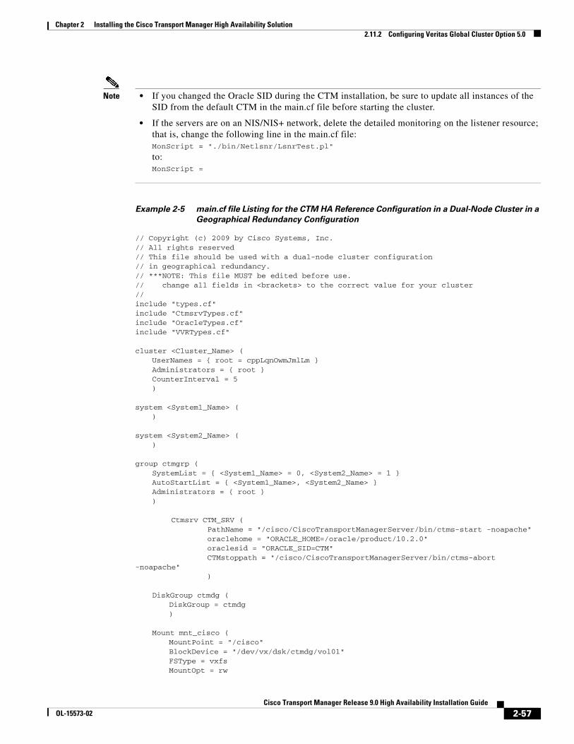
Chapter 2 Installing the Cisco Transport Manager High Availability Solution2.11.2 Configuring Veritas Global Cluster Option 5.0
Note • If you changed the Oracle SID during the CTM installation, be sure to update all instances of the SID from the default CTM in the main.cf file before starting the cluster.
• If the servers are on an NIS/NIS+ network, delete the detailed monitoring on the listener resource; that is, change the following line in the main.cf file: MonScript = "./bin/Netlsnr/LsnrTest.pl"
to:MonScript =
Example 2-5 main.cf file Listing for the CTM HA Reference Configuration in a Dual-Node Cluster in a
Geographical Redundancy Configuration
// Copyright (c) 2009 by Cisco Systems, Inc.// All rights reserved// This file should be used with a dual-node cluster configuration// in geographical redundancy.// ***NOTE: This file MUST be edited before use.// change all fields in <brackets> to the correct value for your cluster//include "types.cf"include "CtmsrvTypes.cf"include "OracleTypes.cf"include "VVRTypes.cf"
cluster <Cluster_Name> (UserNames = { root = cppLqnOwmJmlLm }Administrators = { root }CounterInterval = 5)
system <System1_Name> ()
system <System2_Name> ()
group ctmgrp (SystemList = { <System1_Name> = 0, <System2_Name> = 1 }AutoStartList = { <System1_Name>, <System2_Name> }Administrators = { root })
Ctmsrv CTM_SRV ( PathName = "/cisco/CiscoTransportManagerServer/bin/ctms-start -noapache" oraclehome = "ORACLE_HOME=/oracle/product/10.2.0" oraclesid = "ORACLE_SID=CTM" CTMstoppath = "/cisco/CiscoTransportManagerServer/bin/ctms-abort -noapache" )
DiskGroup ctmdg (DiskGroup = ctmdg)
Mount mnt_cisco (MountPoint = "/cisco"BlockDevice = "/dev/vx/dsk/ctmdg/vol01"FSType = vxfsMountOpt = rw
2-57Cisco Transport Manager Release 9.0 High Availability Installation Guide
OL-15573-02
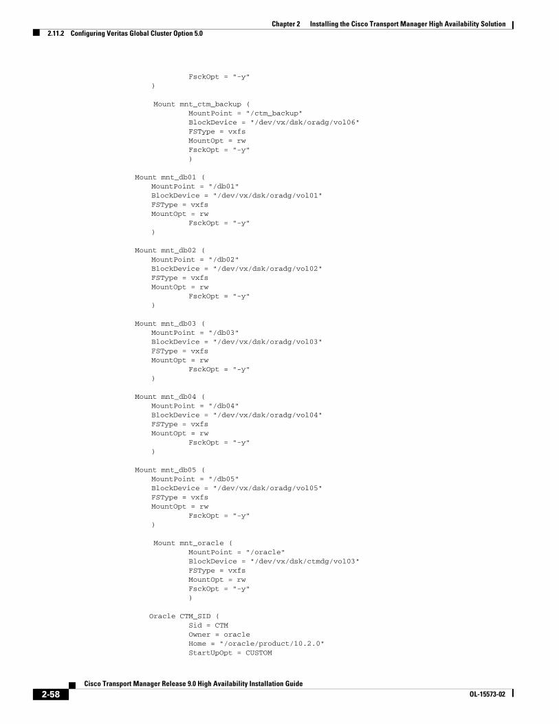
Chapter 2 Installing the Cisco Transport Manager High Availability Solution2.11.2 Configuring Veritas Global Cluster Option 5.0
FsckOpt = "-y")
Mount mnt_ctm_backup ( MountPoint = "/ctm_backup" BlockDevice = "/dev/vx/dsk/oradg/vol06" FSType = vxfs MountOpt = rw FsckOpt = "-y" )
Mount mnt_db01 (MountPoint = "/db01"BlockDevice = "/dev/vx/dsk/oradg/vol01"FSType = vxfsMountOpt = rw
FsckOpt = "-y")
Mount mnt_db02 (MountPoint = "/db02"BlockDevice = "/dev/vx/dsk/oradg/vol02"FSType = vxfsMountOpt = rw
FsckOpt = "-y")
Mount mnt_db03 (MountPoint = "/db03"BlockDevice = "/dev/vx/dsk/oradg/vol03"FSType = vxfsMountOpt = rw
FsckOpt = "-y")
Mount mnt_db04 (MountPoint = "/db04"BlockDevice = "/dev/vx/dsk/oradg/vol04"FSType = vxfsMountOpt = rw
FsckOpt = "-y")
Mount mnt_db05 (MountPoint = "/db05"BlockDevice = "/dev/vx/dsk/oradg/vol05"FSType = vxfsMountOpt = rw
FsckOpt = "-y")
Mount mnt_oracle ( MountPoint = "/oracle" BlockDevice = "/dev/vx/dsk/ctmdg/vol03" FSType = vxfs MountOpt = rw FsckOpt = "-y" )
Oracle CTM_SID ( Sid = CTM Owner = oracle Home = "/oracle/product/10.2.0" StartUpOpt = CUSTOM
2-58Cisco Transport Manager Release 9.0 High Availability Installation Guide
OL-15573-02
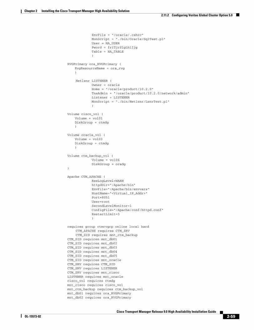
Chapter 2 Installing the Cisco Transport Manager High Availability Solution2.11.2 Configuring Veritas Global Cluster Option 5.0
EnvFile = "/oracle/.cshrc" MonScript = "./bin/Oracle/SqlTest.pl" User = HA_USER Pword = friTjrSlgLhlIjg Table = HA_TABLE )
RVGPrimary ora_RVGPrimary (RvgResourceName = ora_rvg)
Netlsnr LISTENER ( Owner = oracle Home = "/oracle/product/10.2.0" TnsAdmin = "/oracle/product/10.2.0/network/admin" Listener = LISTENER MonScript = "./bin/Netlsnr/LsnrTest.pl" )
Volume cisco_vol (Volume = vol01DiskGroup = ctmdg)
Volume oracle_vol (Volume = vol03DiskGroup = ctmdg)
Volume ctm_backup_vol ( Volume = vol06 DiskGroup = oradg
)
Apache CTM_APACHE ( ResLogLevel=WARN httpdDir="/Apache/bin" EnvFile="/Apache/bin/envvars" HostName="<Virtual_IP_Addr>" Port=8051 User=root SecondLevelMonitor=1 ConfigFile="/Apache/conf/httpd.conf" RestartLimit=3 )
requires group ctmrvgrp online local hard CTM_APACHE requires CTM_SRV CTM_SID requires mnt_ctm_backup
CTM_SID requires mnt_db01CTM_SID requires mnt_db02CTM_SID requires mnt_db03CTM_SID requires mnt_db04CTM_SID requires mnt_db05CTM_SID requires mnt_oracleCTM_SRV requires CTM_SIDCTM_SRV requires LISTENERCTM_SRV requires mnt_ciscoLISTENER requires mnt_oraclecisco_vol requires ctmdgmnt_cisco requires cisco_volmnt_ctm_backup requires ctm_backup_volmnt_db01 requires ora_RVGPrimarymnt_db02 requires ora_RVGPrimary
2-59Cisco Transport Manager Release 9.0 High Availability Installation Guide
OL-15573-02
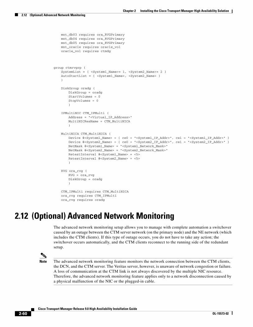
Chapter 2 Installing the Cisco Transport Manager High Availability Solution2.12 (Optional) Advanced Network Monitoring
mnt_db03 requires ora_RVGPrimarymnt_db04 requires ora_RVGPrimarymnt_db05 requires ora_RVGPrimarymnt_oracle requires oracle_voloracle_vol requires ctmdg
group ctmrvgrp (SystemList = { <System1_Name>= 1, <System2_Name>= 2 }AutoStartList = { <System1_Name>, <System2_Name> })
DiskGroup oradg (DiskGroup = oradgStartVolumes = 0StopVolumes = 0)
IPMultiNIC CTM_IPMulti (Address = "<Virtual_IP_Address>"MultiNICResName = CTM_MultiNICA)
MultiNICA CTM_MultiNICA (Device @<System1_Name> = { ce0 = "<System1_IP_Addr>", ce1 = "<System1_IP_Addr>" }Device @<System2_Name> = { ce0 = "<System2_IP_Addr>", ce1 = "<System2_IP_Addr>" }NetMask @<System1_Name> = "<System1_Network_Mask>"NetMask @<System2_Name> = "<System2_Network_Mask>"RetestInterval @<System1_Name> = <5>RetestInterval @<System2_Name> = <5>)
RVG ora_rvg (RVG = ora_rvgDiskGroup = oradg)
CTM_IPMulti requires CTM_MultiNICAora_rvg requires CTM_IPMultiora_rvg requires oradg
2.12 (Optional) Advanced Network MonitoringThe advanced network monitoring setup allows you to manage with complete automation a switchover caused by an outage between the CTM server network (on the primary node) and the NE network (which includes the CTM clients). If this type of outage occurs, you do not have to take any action; the switchover occurs automatically, and the CTM clients reconnect to the running side of the redundant setup.
Note The advanced network monitoring feature monitors the network connection between the CTM clients, the DCN, and the CTM server. The Veritas server, however, is unaware of network congestion or failure. A loss of communication at the CTM link is not always discovered by the multiple NIC resource. Therefore, the advanced network monitoring feature applies only to a network disconnection caused by a physical malfunction of the NIC or the plugged-in cable.
2-60Cisco Transport Manager Release 9.0 High Availability Installation Guide
OL-15573-02
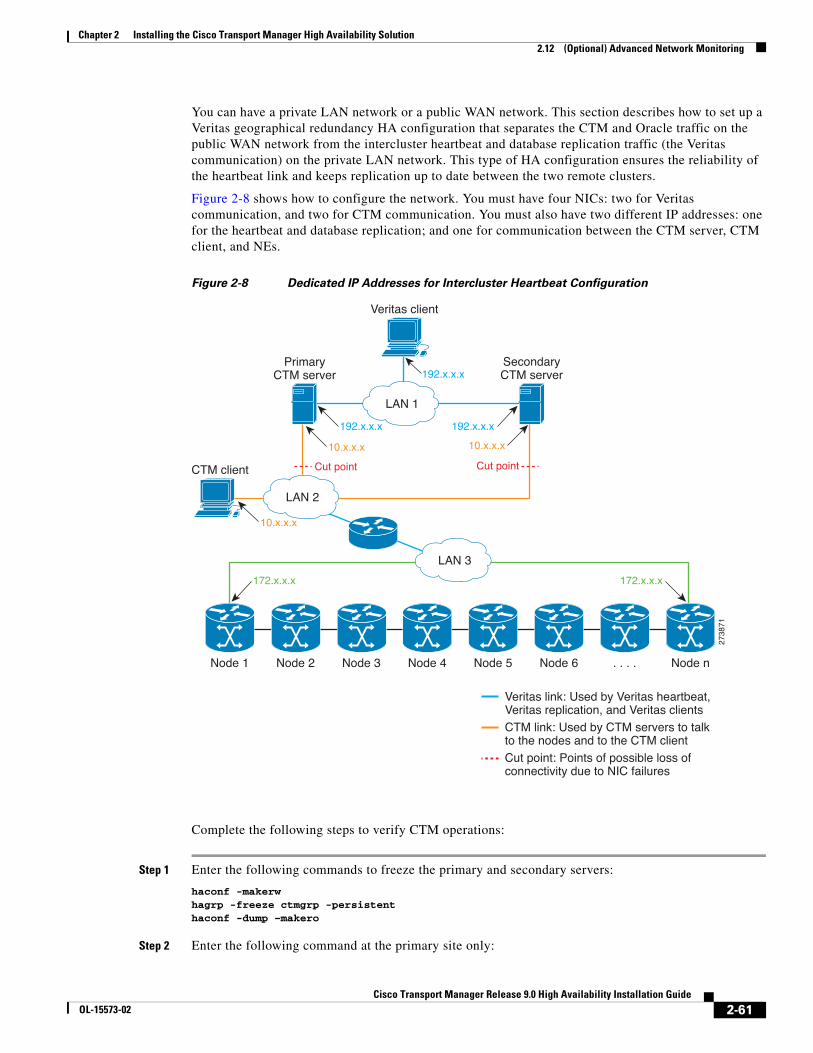
Chapter 2 Installing the Cisco Transport Manager High Availability Solution2.12 (Optional) Advanced Network Monitoring
You can have a private LAN network or a public WAN network. This section describes how to set up a Veritas geographical redundancy HA configuration that separates the CTM and Oracle traffic on the public WAN network from the intercluster heartbeat and database replication traffic (the Veritas communication) on the private LAN network. This type of HA configuration ensures the reliability of the heartbeat link and keeps replication up to date between the two remote clusters.
Figure 2-8 shows how to configure the network. You must have four NICs: two for Veritas communication, and two for CTM communication. You must also have two different IP addresses: one for the heartbeat and database replication; and one for communication between the CTM server, CTM client, and NEs.
Figure 2-8 Dedicated IP Addresses for Intercluster Heartbeat Configuration
Complete the following steps to verify CTM operations:
Step 1 Enter the following commands to freeze the primary and secondary servers:
haconf -makerwhagrp -freeze ctmgrp -persistenthaconf -dump –makero
Step 2 Enter the following command at the primary site only:
Veritas client
LAN 1
192.x.x.x 192.x.x.x
Node 1 Node 2 Node 3 Node 4 Node 5 Node 6 . . . . Node n
192.x.x.x
LAN 2
10.x.x.x 10.x.x.x
Cut point Cut pointCTM client
10.x.x.x
172.x.x.x 172.x.x.x
LAN 3
PrimaryCTM server
SecondaryCTM server
2738
71
Veritas link: Used by Veritas heartbeat, Veritas replication, and Veritas clientsCTM link: Used by CTM servers to talk to the nodes and to the CTM clientCut point: Points of possible loss of connectivity due to NIC failures
2-61Cisco Transport Manager Release 9.0 High Availability Installation Guide
OL-15573-02
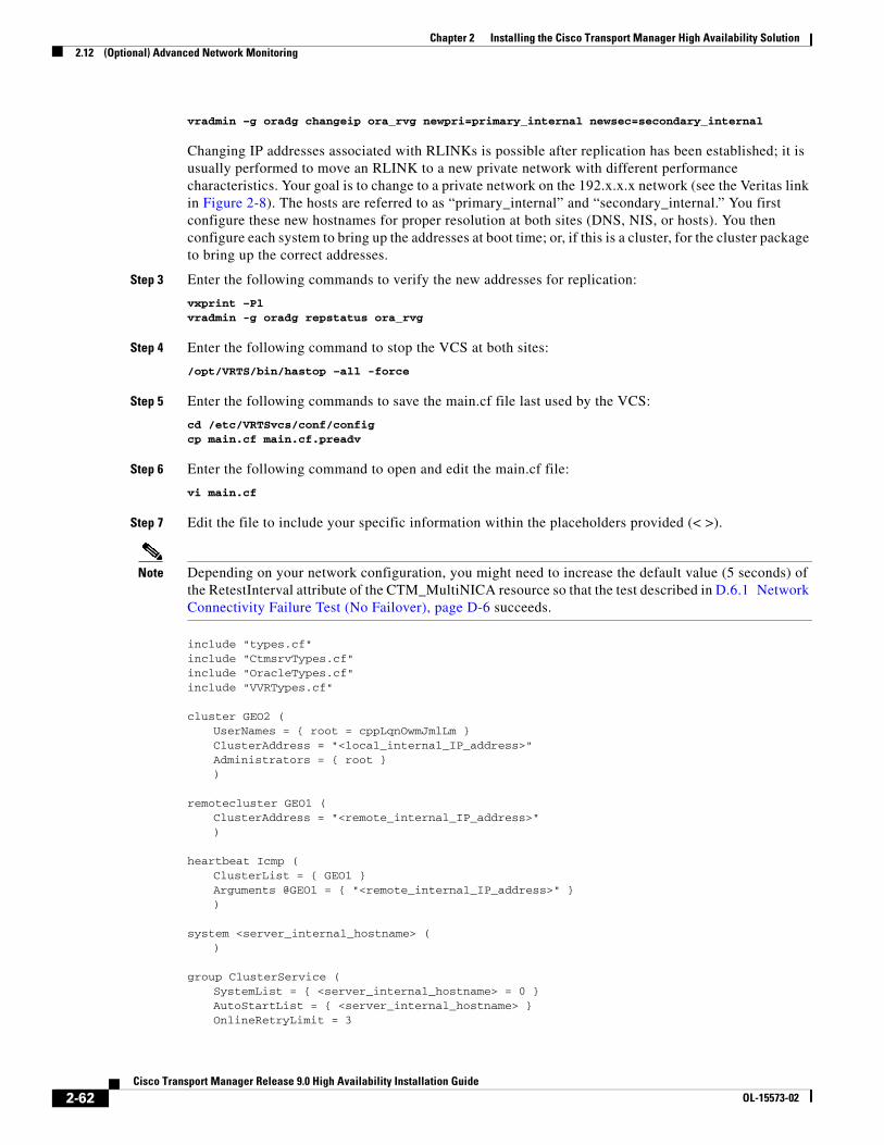
Chapter 2 Installing the Cisco Transport Manager High Availability Solution2.12 (Optional) Advanced Network Monitoring
vradmin –g oradg changeip ora_rvg newpri=primary_internal newsec=secondary_internal
Changing IP addresses associated with RLINKs is possible after replication has been established; it is usually performed to move an RLINK to a new private network with different performance characteristics. Your goal is to change to a private network on the 192.x.x.x network (see the Veritas link in Figure 2-8). The hosts are referred to as “primary_internal” and “secondary_internal.” You first configure these new hostnames for proper resolution at both sites (DNS, NIS, or hosts). You then configure each system to bring up the addresses at boot time; or, if this is a cluster, for the cluster package to bring up the correct addresses.
Step 3 Enter the following commands to verify the new addresses for replication:
vxprint –Plvradmin -g oradg repstatus ora_rvg
Step 4 Enter the following command to stop the VCS at both sites:
/opt/VRTS/bin/hastop –all -force
Step 5 Enter the following commands to save the main.cf file last used by the VCS:
cd /etc/VRTSvcs/conf/configcp main.cf main.cf.preadv
Step 6 Enter the following command to open and edit the main.cf file:
vi main.cf
Step 7 Edit the file to include your specific information within the placeholders provided (< >).
Note Depending on your network configuration, you might need to increase the default value (5 seconds) of the RetestInterval attribute of the CTM_MultiNICA resource so that the test described in D.6.1 Network Connectivity Failure Test (No Failover), page D-6 succeeds.
include "types.cf"include "CtmsrvTypes.cf"include "OracleTypes.cf"include "VVRTypes.cf"
cluster GEO2 (UserNames = { root = cppLqnOwmJmlLm }ClusterAddress = "<local_internal_IP_address>"Administrators = { root })
remotecluster GEO1 (ClusterAddress = "<remote_internal_IP_address>")
heartbeat Icmp (ClusterList = { GEO1 }Arguments @GEO1 = { "<remote_internal_IP_address>" })
system <server_internal_hostname> ()
group ClusterService (SystemList = { <server_internal_hostname> = 0 }AutoStartList = { <server_internal_hostname> }OnlineRetryLimit = 3
2-62Cisco Transport Manager Release 9.0 High Availability Installation Guide
OL-15573-02
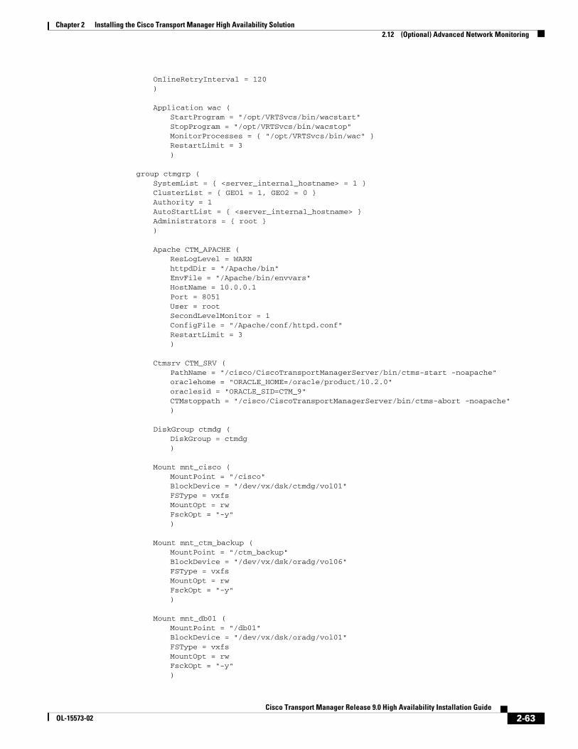
Chapter 2 Installing the Cisco Transport Manager High Availability Solution2.12 (Optional) Advanced Network Monitoring
OnlineRetryInterval = 120)
Application wac (StartProgram = "/opt/VRTSvcs/bin/wacstart"StopProgram = "/opt/VRTSvcs/bin/wacstop"MonitorProcesses = { "/opt/VRTSvcs/bin/wac" }RestartLimit = 3)
group ctmgrp (SystemList = { <server_internal_hostname> = 1 }ClusterList = { GEO1 = 1, GEO2 = 0 }Authority = 1AutoStartList = { <server_internal_hostname> }Administrators = { root })
Apache CTM_APACHE (ResLogLevel = WARNhttpdDir = "/Apache/bin"EnvFile = "/Apache/bin/envvars"HostName = 10.0.0.1Port = 8051User = rootSecondLevelMonitor = 1ConfigFile = "/Apache/conf/httpd.conf"RestartLimit = 3)
Ctmsrv CTM_SRV (PathName = "/cisco/CiscoTransportManagerServer/bin/ctms-start -noapache"oraclehome = "ORACLE_HOME=/oracle/product/10.2.0"oraclesid = "ORACLE_SID=CTM_9"CTMstoppath = "/cisco/CiscoTransportManagerServer/bin/ctms-abort -noapache")
DiskGroup ctmdg (DiskGroup = ctmdg)
Mount mnt_cisco (MountPoint = "/cisco"BlockDevice = "/dev/vx/dsk/ctmdg/vol01"FSType = vxfsMountOpt = rwFsckOpt = "-y")
Mount mnt_ctm_backup (MountPoint = "/ctm_backup"BlockDevice = "/dev/vx/dsk/oradg/vol06"FSType = vxfsMountOpt = rwFsckOpt = "-y")
Mount mnt_db01 (MountPoint = "/db01"BlockDevice = "/dev/vx/dsk/oradg/vol01"FSType = vxfsMountOpt = rwFsckOpt = "-y")
2-63Cisco Transport Manager Release 9.0 High Availability Installation Guide
OL-15573-02
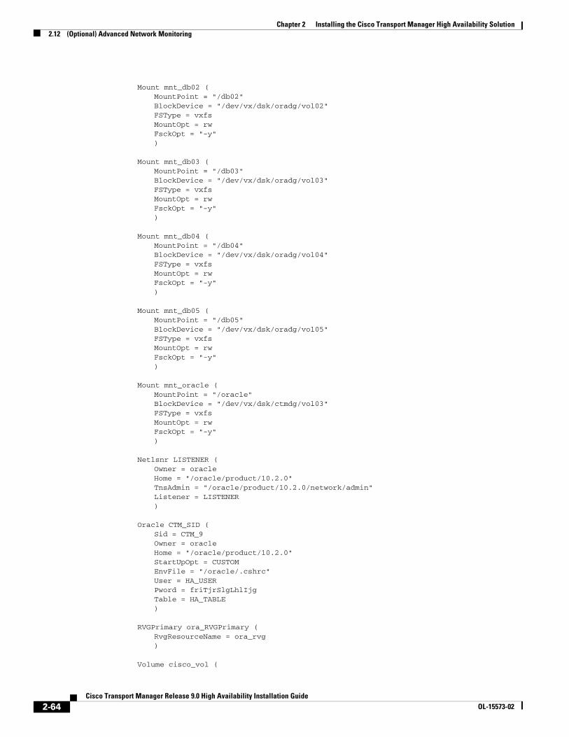
Chapter 2 Installing the Cisco Transport Manager High Availability Solution2.12 (Optional) Advanced Network Monitoring
Mount mnt_db02 (MountPoint = "/db02"BlockDevice = "/dev/vx/dsk/oradg/vol02"FSType = vxfsMountOpt = rwFsckOpt = "-y")
Mount mnt_db03 (MountPoint = "/db03"BlockDevice = "/dev/vx/dsk/oradg/vol03"FSType = vxfsMountOpt = rwFsckOpt = "-y")
Mount mnt_db04 (MountPoint = "/db04"BlockDevice = "/dev/vx/dsk/oradg/vol04"FSType = vxfsMountOpt = rwFsckOpt = "-y")
Mount mnt_db05 (MountPoint = "/db05"BlockDevice = "/dev/vx/dsk/oradg/vol05"FSType = vxfsMountOpt = rwFsckOpt = "-y")
Mount mnt_oracle (MountPoint = "/oracle"BlockDevice = "/dev/vx/dsk/ctmdg/vol03"FSType = vxfsMountOpt = rwFsckOpt = "-y")
Netlsnr LISTENER (Owner = oracleHome = "/oracle/product/10.2.0"TnsAdmin = "/oracle/product/10.2.0/network/admin"Listener = LISTENER)
Oracle CTM_SID (Sid = CTM_9Owner = oracleHome = "/oracle/product/10.2.0"StartUpOpt = CUSTOMEnvFile = "/oracle/.cshrc"User = HA_USERPword = friTjrSlgLhlIjgTable = HA_TABLE)
RVGPrimary ora_RVGPrimary (RvgResourceName = ora_rvg)
Volume cisco_vol (
2-64Cisco Transport Manager Release 9.0 High Availability Installation Guide
OL-15573-02
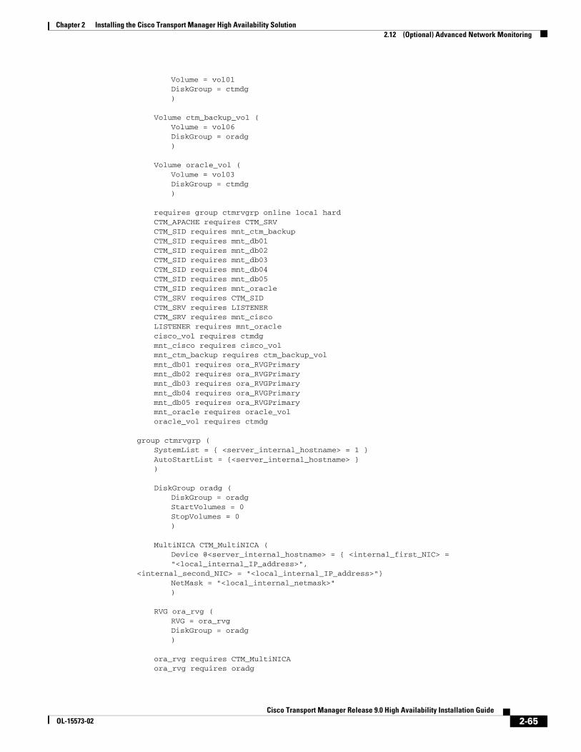
Chapter 2 Installing the Cisco Transport Manager High Availability Solution2.12 (Optional) Advanced Network Monitoring
Volume = vol01DiskGroup = ctmdg)
Volume ctm_backup_vol (Volume = vol06DiskGroup = oradg)
Volume oracle_vol (Volume = vol03DiskGroup = ctmdg)
requires group ctmrvgrp online local hardCTM_APACHE requires CTM_SRVCTM_SID requires mnt_ctm_backupCTM_SID requires mnt_db01CTM_SID requires mnt_db02CTM_SID requires mnt_db03CTM_SID requires mnt_db04CTM_SID requires mnt_db05CTM_SID requires mnt_oracleCTM_SRV requires CTM_SIDCTM_SRV requires LISTENERCTM_SRV requires mnt_ciscoLISTENER requires mnt_oraclecisco_vol requires ctmdgmnt_cisco requires cisco_volmnt_ctm_backup requires ctm_backup_volmnt_db01 requires ora_RVGPrimarymnt_db02 requires ora_RVGPrimarymnt_db03 requires ora_RVGPrimarymnt_db04 requires ora_RVGPrimarymnt_db05 requires ora_RVGPrimarymnt_oracle requires oracle_voloracle_vol requires ctmdg
group ctmrvgrp (SystemList = { <server_internal_hostname> = 1 }AutoStartList = {<server_internal_hostname> })
DiskGroup oradg (DiskGroup = oradgStartVolumes = 0StopVolumes = 0)
MultiNICA CTM_MultiNICA (Device @<server_internal_hostname> = { <internal_first_NIC> = "<local_internal_IP_address>",
<internal_second_NIC> = "<local_internal_IP_address>"}NetMask = "<local_internal_netmask>")
RVG ora_rvg (RVG = ora_rvgDiskGroup = oradg)
ora_rvg requires CTM_MultiNICAora_rvg requires oradg
2-65Cisco Transport Manager Release 9.0 High Availability Installation Guide
OL-15573-02
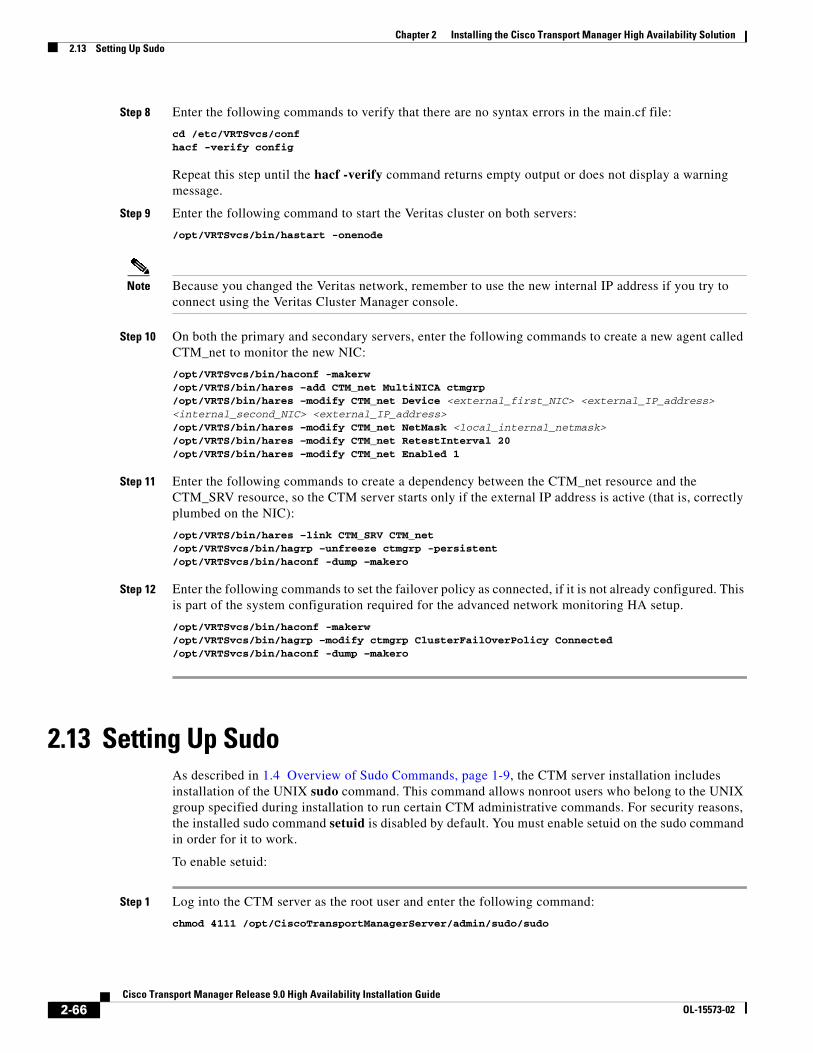
Chapter 2 Installing the Cisco Transport Manager High Availability Solution2.13 Setting Up Sudo
Step 8 Enter the following commands to verify that there are no syntax errors in the main.cf file:
cd /etc/VRTSvcs/confhacf -verify config
Repeat this step until the hacf -verify command returns empty output or does not display a warning message.
Step 9 Enter the following command to start the Veritas cluster on both servers:
/opt/VRTSvcs/bin/hastart -onenode
Note Because you changed the Veritas network, remember to use the new internal IP address if you try to connect using the Veritas Cluster Manager console.
Step 10 On both the primary and secondary servers, enter the following commands to create a new agent called CTM_net to monitor the new NIC:
/opt/VRTSvcs/bin/haconf -makerw/opt/VRTS/bin/hares –add CTM_net MultiNICA ctmgrp/opt/VRTS/bin/hares –modify CTM_net Device <external_first_NIC> <external_IP_address><internal_second_NIC> <external_IP_address>/opt/VRTS/bin/hares –modify CTM_net NetMask <local_internal_netmask>/opt/VRTS/bin/hares –modify CTM_net RetestInterval 20/opt/VRTS/bin/hares –modify CTM_net Enabled 1
Step 11 Enter the following commands to create a dependency between the CTM_net resource and the CTM_SRV resource, so the CTM server starts only if the external IP address is active (that is, correctly plumbed on the NIC):
/opt/VRTS/bin/hares –link CTM_SRV CTM_net/opt/VRTSvcs/bin/hagrp –unfreeze ctmgrp -persistent/opt/VRTSvcs/bin/haconf -dump –makero
Step 12 Enter the following commands to set the failover policy as connected, if it is not already configured. This is part of the system configuration required for the advanced network monitoring HA setup.
/opt/VRTSvcs/bin/haconf -makerw/opt/VRTSvcs/bin/hagrp –modify ctmgrp ClusterFailOverPolicy Connected/opt/VRTSvcs/bin/haconf -dump –makero
2.13 Setting Up SudoAs described in 1.4 Overview of Sudo Commands, page 1-9, the CTM server installation includes installation of the UNIX sudo command. This command allows nonroot users who belong to the UNIX group specified during installation to run certain CTM administrative commands. For security reasons, the installed sudo command setuid is disabled by default. You must enable setuid on the sudo command in order for it to work.
To enable setuid:
Step 1 Log into the CTM server as the root user and enter the following command:
chmod 4111 /opt/CiscoTransportManagerServer/admin/sudo/sudo
2-66Cisco Transport Manager Release 9.0 High Availability Installation Guide
OL-15573-02

Chapter 2 Installing the Cisco Transport Manager High Availability Solution2.13 Setting Up Sudo
Step 2 Verify that users have /opt/CiscoTransportManagerServer/admin/sudo in their path environment, so that they can execute sudo without having to specify the full path.
Note Sudo is often available in the standard UNIX environment established by the CTM server system administrator. If so, it is not necessary to use the sudo bundled with CTM or follow this procedure to enable it. Instead, you can use the sudo established by the system administrator.
2-67Cisco Transport Manager Release 9.0 High Availability Installation Guide
OL-15573-02

Chapter 2 Installing the Cisco Transport Manager High Availability Solution2.13 Setting Up Sudo
2-68Cisco Transport Manager Release 9.0 High Availability Installation Guide
OL-15573-02