Embed Size (px)
Citation preview

1
PETROWORKS
OFF-ROAD PRODUCTS
Installing Petroworks Wire Harness for 1.6 16 valve engines Thanks for giving Petroworks the opportunity to provide you with what we feel is the best 1.6 16v Harness conversion available on the market. We know there are other harness options on the market to choose from, however we feel that our harness is by far the best harness conversion on the market hands down. We believe that you get what you pay for and our competitors know what their work is worth. NOTE: This document is a general guide to installing a Petroworks Wiring Harness Conversion for the 1.6 16v motors. All harnesses are built with soldered connections and shrink wrapped. We try to maintain all the original wire color codes to better help diagnose any issues that you may have during the life of ownership. A couple of the wires in the harness are longer than in the stock harness so it is necessary to change wire color in the harness. All wires are the correct colr at each end. What this means is that if you are tracing out a wire, start with either the computer or the suspected sensor to trace back. You may find a different color in between in some instances. We do not recommend using Crimp connectors to attach the wires as they do not provide a solid connection and come loose and corrode over time. Our current design (2013) harnesses have the Starter Relay (clicky starter fix) built into the harness, and we have added two 20amp fuses to the harness. One fuse is the main power for the computer, and the other fuse is for the Starter Relay. The main power for the harness/computer is fed from the Starter Solenoid (See Figure J) positive terminal. Depending on which motor/harness setup we made for you the only difference between the two harnesses is the Distributor connections. On ODBI motors you will have 3 connections, Igniter, Coil, and Distributor. On ODBII motors you will have only the Distributor connector. These motors have the Coil and Igniter inside the distributor. See Figures K and L.
2
Recommended Tools
Dykes (wire cutters) Quality Electrical tape (Scotch Super 33+) Solder Soldering Iron Shrink Tubing
1. Remove the battery, remove the Samurai ECU (Behind the glove compartment), pull the
wires that go into the ECU, the W/Y wire and harness connector and pull them back through the firewall. Save the little firewall grommet as you can use this to reinstall the new harness.
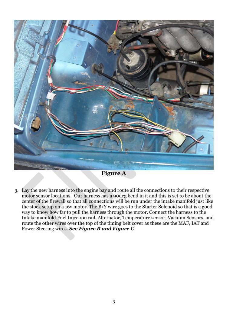
2. Remove all the tape across the firewall about half way, and half way along the fender well. You will pretty much be removing every wire that goes to the ECU as all of these go to the Samurai Carb. When you are complete. See Figure A.
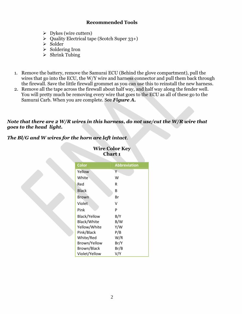
Note that there are 2 W/R wires in this harness, do not use/cut the W/R wire that goes to the head light. The Bl/G and W wires for the horn are left intact.
Wire Color Key Chart 1
Color Abbreviation
Yellow Y
White W
Red R
Black B
Brown Br
Violet V
Pink P
Black/Yellow Black/White Yellow/White Pink/Black White/Red Brown/Yellow Brown/Black Violet/Yellow
B/Y B/W Y/W P/B W/R Br/Y Br/B V/Y
3
Figure A
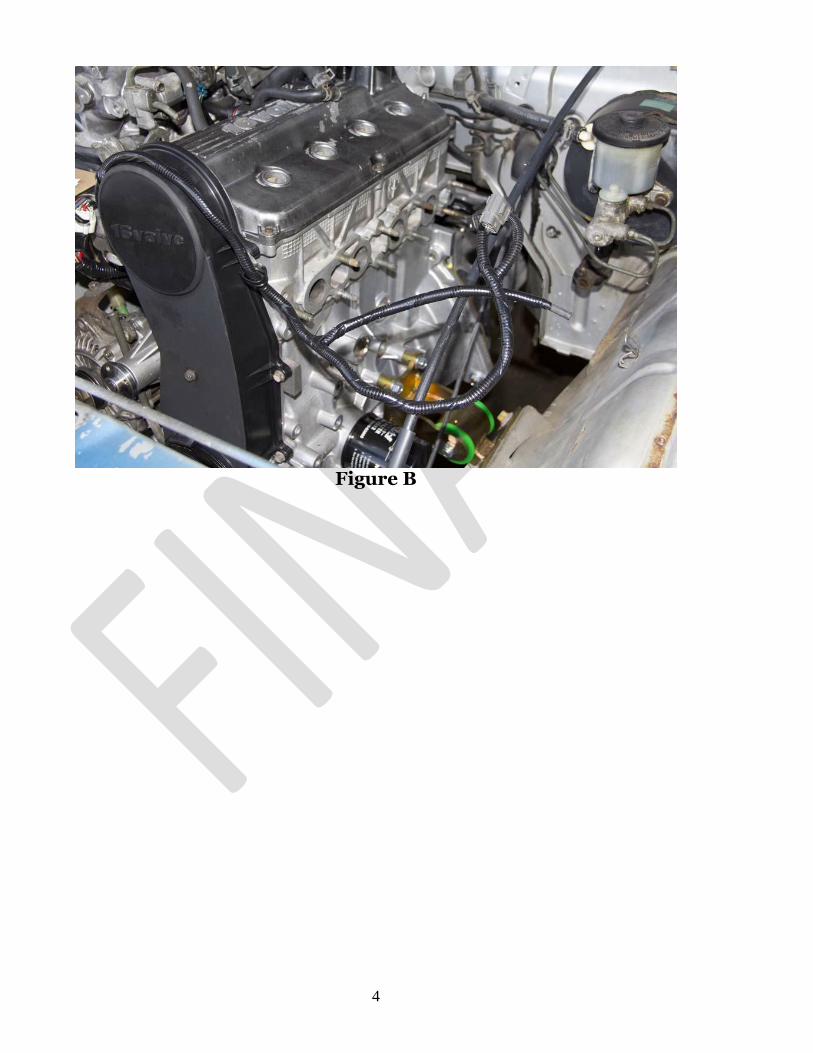
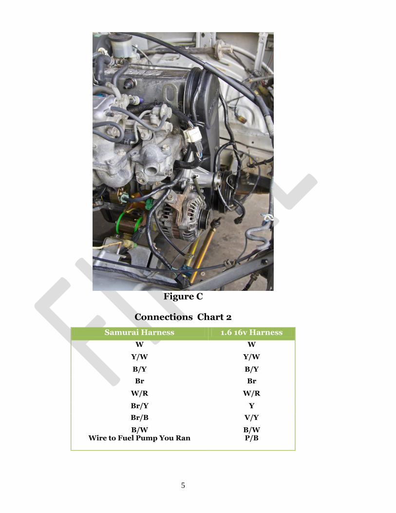
3. Lay the new harness into the engine bay and route all the connections to their respective motor sensor locations. Our harness has a 90deg bend in it and this is set to be about the center of the firewall so that all connections will be run under the intake manifold just like the stock setup on a 16v motor. The B/Y wire goes to the Starter Solenoid so that is a good way to know how far to pull the harness through the motor. Connect the harness to the Intake manifold Fuel Injection rail, Alternator, Temperature sensor, Vacuum Sensors, and route the other wires over the top of the timing belt cover as these are the MAF, IAT and Power Steering wires. See Figure B and Figure C.
4
Figure B
5
Figure C
Connections Chart 2
Samurai Harness 1.6 16v Harness
W W
Y/W Y/W
B/Y B/Y
Br Br
W/R W/R
Br/Y Y
Br/B V/Y
B/W Wire to Fuel Pump You Ran
B/W P/B
6
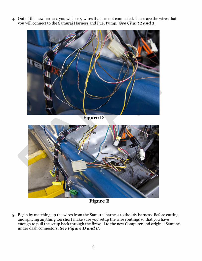
4. Out of the new harness you will see 9 wires that are not connected. These are the wires that you will connect to the Samurai Harness and Fuel Pump. See Chart 1 and 2.
Figure D
Figure E
5. Begin by matching up the wires from the Samurai harness to the 16v harness. Before cutting and splicing anything too short make sure you setup the wire routings so that you have enough to pull the setup back through the firewall to the new Computer and original Samurai under dash connectors. See Figure D and E.
7
Figure F
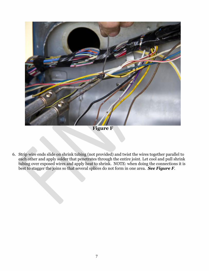
6. Strip wire ends slide on shrink tubing (not provided) and twist the wires together parallel to
each other and apply solder that penetrates through the entire joint. Let cool and pull shrink tubing over exposed wires and apply heat to shrink. NOTE: when doing the connections it is best to stagger the joins so that several splices do not form in one area. See Figure F.
8
Figure G
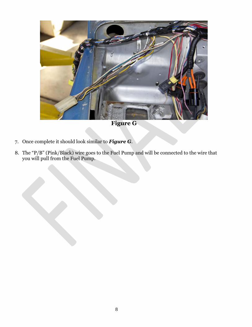
7. Once complete it should look similar to Figure G.
8. The “P/B” (Pink/Black) wire goes to the Fuel Pump and will be connected to the wire that
you will pull from the Fuel Pump.
9
Figure H
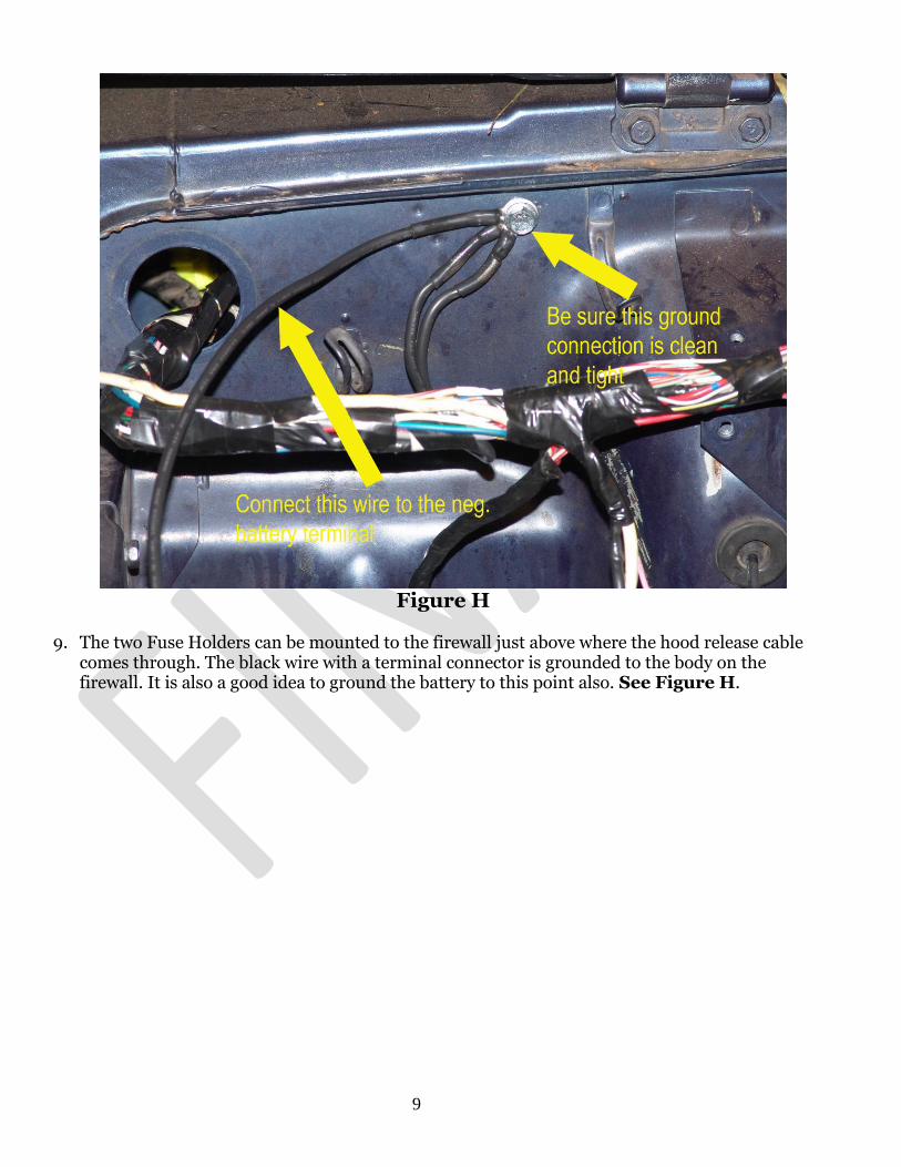
9. The two Fuse Holders can be mounted to the firewall just above where the hood release cable
comes through. The black wire with a terminal connector is grounded to the body on the firewall. It is also a good idea to ground the battery to this point also. See Figure H.
10
Figure I
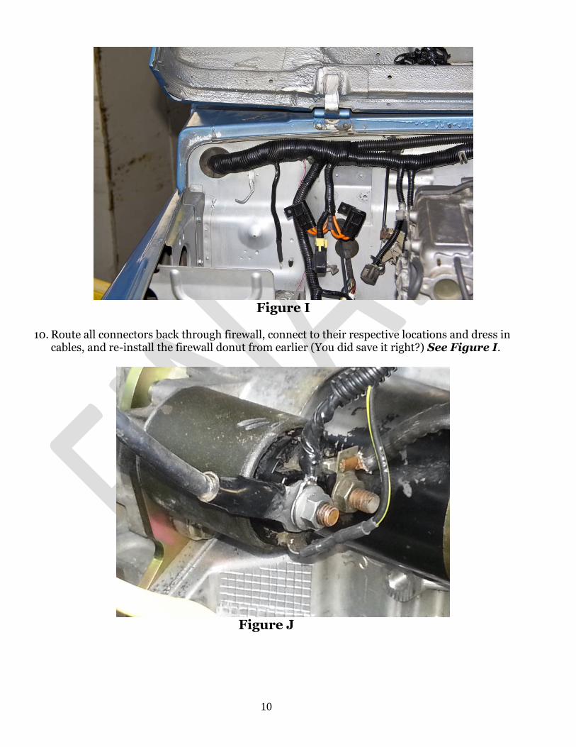
10. Route all connectors back through firewall, connect to their respective locations and dress in
cables, and re-install the firewall donut from earlier (You did save it right?) See Figure I.
Figure J
11
11. As mentioned in the notes the computer and harness get their power from the positive terminal on the Starter Solenoid. Connect the B/Y wire with a terminal on it and the extra ring terminal to the Positive Post on the Starter Solenoid. See Figure J.
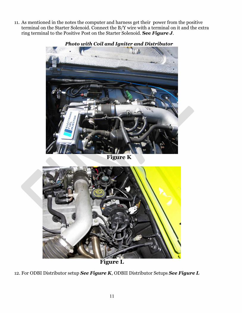
Photo with Coil and Igniter and Distributor
Figure K
Figure L
12. For ODBI Distributor setup See Figure K, ODBII Distributor Setups See Figure L
12
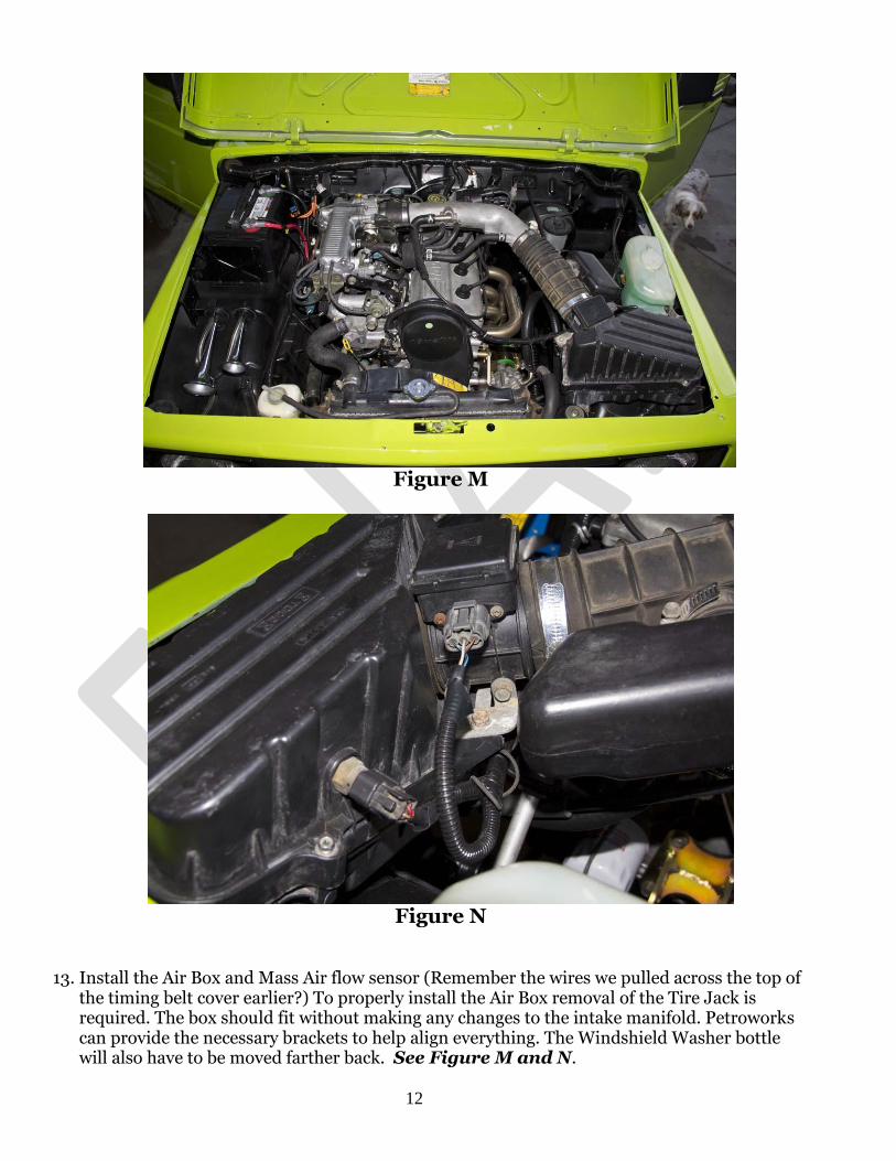
Figure M
Figure N
13. Install the Air Box and Mass Air flow sensor (Remember the wires we pulled across the top of the timing belt cover earlier?) To properly install the Air Box removal of the Tire Jack is required. The box should fit without making any changes to the intake manifold. Petroworks can provide the necessary brackets to help align everything. The Windshield Washer bottle will also have to be moved farther back. See Figure M and N.

13
Wiring for VSS Speedometer Cluster
When switching to a 1.6 16v Motor it is necessary to install a VSS (Vehicle Speed Sensor) into
the Speedometer. The computer needs a signal from the Speedometer in order to adjust the timing while the vehicle is moving. Petroworks can provide this service if you have not already had it done.
Once complete you have to setup your under dash wiring harness to send this signal back to
the computer. With the harness you should have gotten a small wire with a connector on it to install into your speedometer wiring harness connector.
Along the inside of the dash there is a bundle of wires that are just taped up. On the left side
of this bundle, cut the tape to spread out the wires and locate the Br/Y wire. Cut this wire and pull some out on the side running towards the driver side.
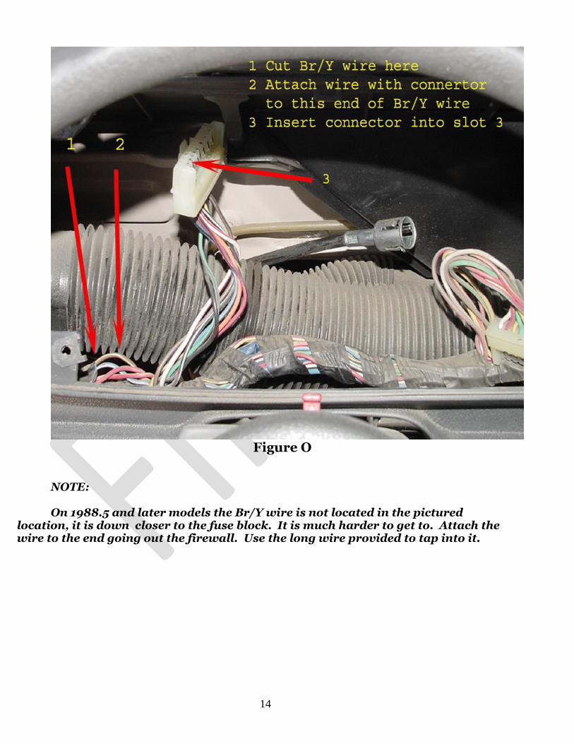
Strip the wire and solder in the provided wire. Then install it into Connect in Slot 3. See
Figure O
14
Figure O
NOTE: On 1988.5 and later models the Br/Y wire is not located in the pictured
location, it is down closer to the fuse block. It is much harder to get to. Attach the wire to the end going out the firewall. Use the long wire provided to tap into it.


![Harness Description List (KBL) - ecad-if.de · Harness Description List (KBL) Version ... - Harness components like connectors, wires, ... General_wire: General_wire [0..*]](https://img.pdfslide.net/doc/110x75/5aeab5eb7f8b9a45568c2306/harness-description-list-kbl-ecad-ifde-description-list-kbl-version-.jpg)