Embed Size (px)
Citation preview
1
Instantaneous Deicing of Freezer Ice via Ultrasonic
Actuation
Jose Palacios1, Edward Smith2, and Joseph Rose3
The Pennsylvania State University, University Park, PA, 16802
and
Roger Royer4
FBS Worldwide Inc., State College, PA, 16803
A low-power, non-thermal, ultrasonic deicing system is introduced as a potential deicing
system for helicopter rotor blades that are currently being used. In this research effort,
ultrasonic actuator disks excite isotropic plates and airfoil-shaped structures that are
representative of helicopter leading edge protection caps. The system generates delaminating
ultrasonic transverse shear stresses at the interface of accreted ice, de-bonding thin ice
layers (< 3 mm thick) as they form on the isotropic host structure. A finite element model of
the proposed actuator and of the isotropic plates is used to guide the selection of the actuator
prototypes. Several actuator-isotropic plate structures are fabricated and tested under
freezer ice conditions. Test results demonstrate that radial resonance disk actuators (28 – 32
KHz) create ultrasonic transverse shear stresses capable of instantaneously delaminating ice
layers. At environment temperatures of -20º C, the system delaminates 2.5 mm thick ice
layers with power input densities as low as 0.07 W/cm2 (0.5 W/in
2). The effects of ice
thickness on the instantaneous delamination of accreted ice is studied by modeling the
interface stresses on three different ice thickness layers and correlating the predictions with
experimental results. The finite element modeling predicts the delamination patterns of the
accreted ice layers. Models also predict within 15% the required input voltage to promote
instantaneous ice de-bonding. The actuators were selected such that during excitation, the
temperature of the PZT material remained well below freezing, hence eliminating heat
propagation and melting as the main source of ice delamination.
1 Research Associate, Department of Aerospace Eng., 229 Hammond Bldg. and AIAA Member 2 Professor Aerospace Eng., 231D Hammond Bldg., and AIAA Member 3 Paul Morrow Professor Eng. Science and Mechanics, 0212 Earth & Eng. Sciences, and AIAA Member 4 Director of Technolgy & Bussines Develop., 143 Hawbaker Industrial Dr., Suite 102
2
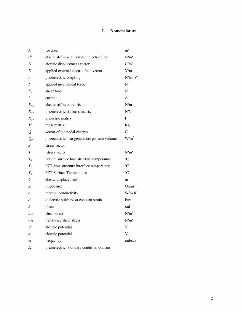
I. Nomenclature
A ice area m2
cE elastic stiffness at constant electric field N/m2
D electric displacement vector C/m2
E applied external electric field vector V/m
e piezoelectric coupling N/(m V)
F applied mechanical force N
Fs shear force N
I current A
Kuu elastic stiffness matrix N/m
Kuφ piezoelectric stiffness matrix N/V
Kφφ dielectric matrix F
M mass matrix Kg
Q vector of the nodal charges C
QP piezoelectric heat generation per unit volume W/m3
S strain vector
T stress vector N/m2
T0 bottom surface host structure temperature ºC
T1 PZT-host structure interface temperature ºC
T2 PZT Surface Temperature ºC
U elastic displacement m
Z impedance Ohms
α thermal conductivity W/m K
εS dielectric stiffness at constant strain F/m
θ phase rad
σXY shear stress N/m2
σZX transverse shear stress N/m2
Φ electric potential V
φ electric potential V
ω frequency rad/sec
Ω piezoelectric boundary condition domain
3
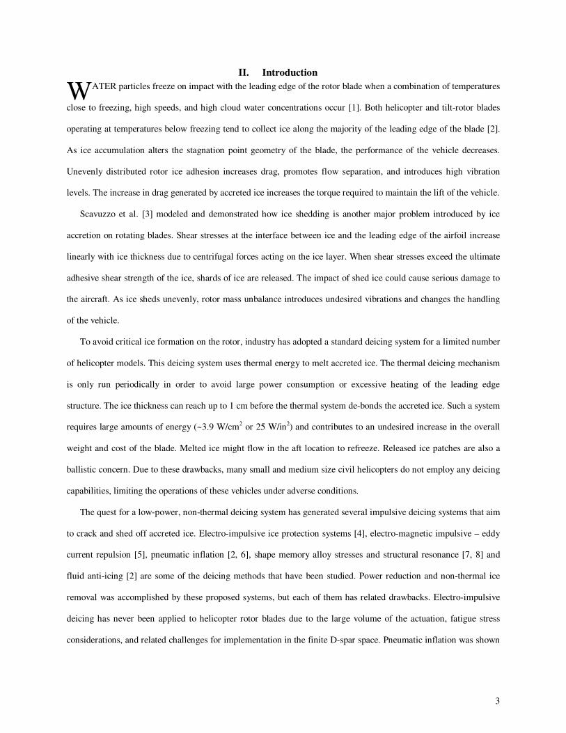
II. Introduction
ATER particles freeze on impact with the leading edge of the rotor blade when a combination of temperatures
close to freezing, high speeds, and high cloud water concentrations occur [1]. Both helicopter and tilt-rotor blades
operating at temperatures below freezing tend to collect ice along the majority of the leading edge of the blade [2].
As ice accumulation alters the stagnation point geometry of the blade, the performance of the vehicle decreases.
Unevenly distributed rotor ice adhesion increases drag, promotes flow separation, and introduces high vibration
levels. The increase in drag generated by accreted ice increases the torque required to maintain the lift of the vehicle.
Scavuzzo et al. [3] modeled and demonstrated how ice shedding is another major problem introduced by ice
accretion on rotating blades. Shear stresses at the interface between ice and the leading edge of the airfoil increase
linearly with ice thickness due to centrifugal forces acting on the ice layer. When shear stresses exceed the ultimate
adhesive shear strength of the ice, shards of ice are released. The impact of shed ice could cause serious damage to
the aircraft. As ice sheds unevenly, rotor mass unbalance introduces undesired vibrations and changes the handling
of the vehicle.
To avoid critical ice formation on the rotor, industry has adopted a standard deicing system for a limited number
of helicopter models. This deicing system uses thermal energy to melt accreted ice. The thermal deicing mechanism
is only run periodically in order to avoid large power consumption or excessive heating of the leading edge
structure. The ice thickness can reach up to 1 cm before the thermal system de-bonds the accreted ice. Such a system
requires large amounts of energy (~3.9 W/cm2 or 25 W/in2) and contributes to an undesired increase in the overall
weight and cost of the blade. Melted ice might flow in the aft location to refreeze. Released ice patches are also a
ballistic concern. Due to these drawbacks, many small and medium size civil helicopters do not employ any deicing
capabilities, limiting the operations of these vehicles under adverse conditions.
The quest for a low-power, non-thermal deicing system has generated several impulsive deicing systems that aim
to crack and shed off accreted ice. Electro-impulsive ice protection systems [4], electro-magnetic impulsive – eddy
current repulsion [5], pneumatic inflation [2, 6], shape memory alloy stresses and structural resonance [7, 8] and
fluid anti-icing [2] are some of the deicing methods that have been studied. Power reduction and non-thermal ice
removal was accomplished by these proposed systems, but each of them has related drawbacks. Electro-impulsive
deicing has never been applied to helicopter rotor blades due to the large volume of the actuation, fatigue stress
considerations, and related challenges for implementation in the finite D-spar space. Pneumatic inflation was shown
W
4
to erode when placed in helicopter leading edge areas. Detached ice impact concerns remained with pneumatic
leading edge deicing. Structural resonance systems also required ice to accrete to considerable thickness and stresses
created in the blade are a concern for D-spar composite delamination. Fluid anti-icing requires large amounts of
fluid to be carried on board. The deicing fluid has to be transferred to the blades via complicated slip rings. In
addition, leading edge orifice clogging is a concern for this type of system.
Ramanathan et al. [9] proposed the use of ultrasonic shear waves as a low-power ice protection system. In his
research, a 1 MHz shear mode piezoelectric patch was applied to an isotropic plate with a layer of ice. Ice interface
melting slowly took place and approximately 100 seconds after the actuator was turned on, the ice patch
delaminated. Venna et al. described similar melting patterns at lower excitation frequencies (1,000 Hz) that
introduced localized high stress due to resonating piezoelectric actuators [7]. Palacios et al. [10] also observed
melting of accreted ice layers under the effects of ultrasonic shear vibration. The accreted ice layers showed
instantaneous microscopic ice cracking and melting with resonating piezoelectric shear actuators (130 KHz). Heat
propagation from the actuator, as a major source of energy melting the ice interface, is a concern for all the high
frequency vibration research mentioned above. Heat propagation as the main source for ice removal presents
challenges when combined with new leading edges high erosion resistant polymer based materials. The lower
thermal propagation properties of these materials introduce melting concerns.
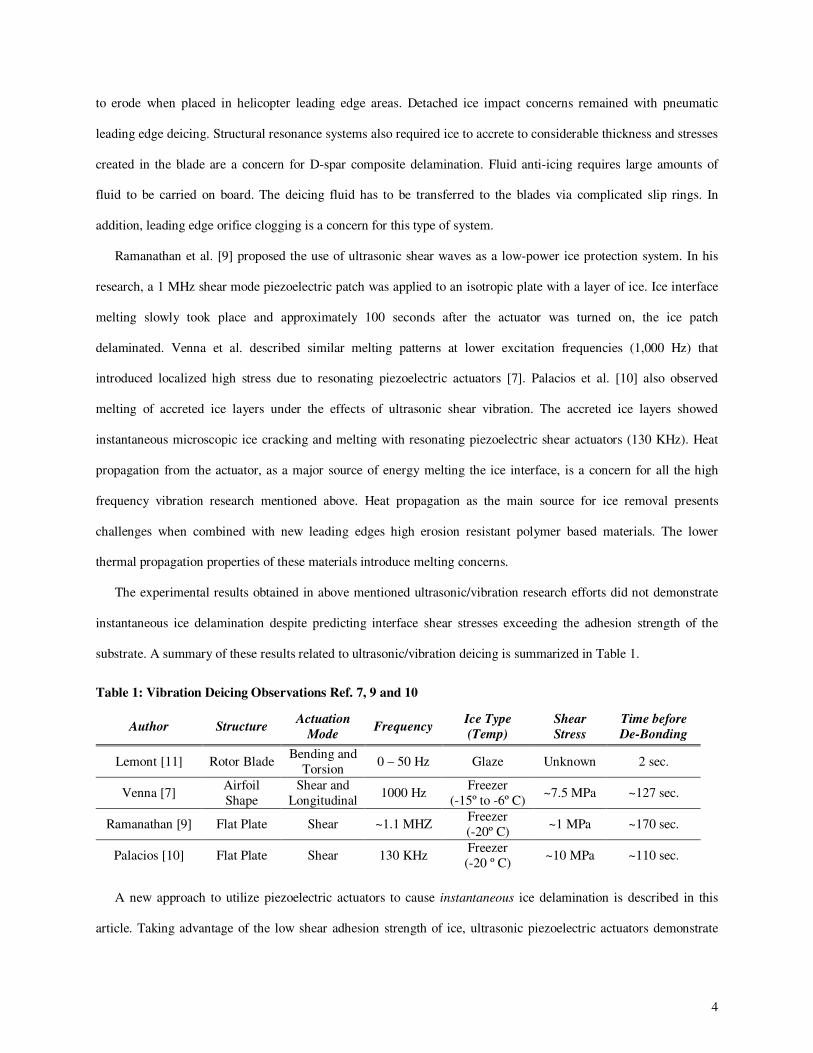
The experimental results obtained in above mentioned ultrasonic/vibration research efforts did not demonstrate
instantaneous ice delamination despite predicting interface shear stresses exceeding the adhesion strength of the
substrate. A summary of these results related to ultrasonic/vibration deicing is summarized in Table 1.
A new approach to utilize piezoelectric actuators to cause instantaneous ice delamination is described in this
article. Taking advantage of the low shear adhesion strength of ice, ultrasonic piezoelectric actuators demonstrate
Table 1: Vibration Deicing Observations Ref. 7, 9 and 10
Author Structure Actuation
Mode Frequency
Ice Type
(Temp)
Shear
Stress
Time before
De-Bonding
Lemont [11] Rotor Blade Bending and
Torsion 0 – 50 Hz Glaze Unknown 2 sec.
Venna [7] Airfoil
Shape
Shear and
Longitudinal 1000 Hz
Freezer
(-15º to -6º C) ~7.5 MPa ~127 sec.
Ramanathan [9] Flat Plate Shear ~1.1 MHZ Freezer
(-20º C) ~1 MPa ~170 sec.
Palacios [10] Flat Plate Shear 130 KHz Freezer
(-20 º C) ~10 MPa ~110 sec.
5
the capability of delaminating thin ice layers (< 3 mm) without any time delay after the actuator is turned on.
Centrifugal forces introduced on accreted ice layers during rotor operation in icing conditions will reduce required
interface stresses. Instantaneous ice delamination occurs while the actuator temperature remains well under freezing
temperatures, eliminating heat propagation as the main source of ice de-bonding.
The objectives of the research presented in this paper are 1) to develop a design procedure for the selection of
ultrasonic deicing actuators, 2) to present experimental results demonstrating instantaneous delamination of freezer
ice, and 3) to correlate these results with predictions. Predictions of the transverse shear stresses between an
isotropic host structure and an accreted ice layer under the effects of ultrasonic vibration were performed using finite
element analysis. All the proof-of-concept experiments presented in this article were conducted with freezer ice.
III. Ice Adhesion Strength Measurement
Extensive work to experimentally determine the adhesion strength of ice to different materials and under
different icing conditions has been conducted by multiple authors [3, 12-17]. Ramanthan et al. [9] and Venna et al.
[7] presented literature reviews on the subject. Based on the experimental shear adhesion strength measurements
between ice and steel that were presented in the referenced literature, the expected shear adhesion strength value of
refrigerated glaze ice can be expected to range between 0.24 and 1.7 MPa. Some authors present lower shear
adhesion strengths for wind tunnel impinging ice than freezer ice, but there are also arguments stating the opposite is
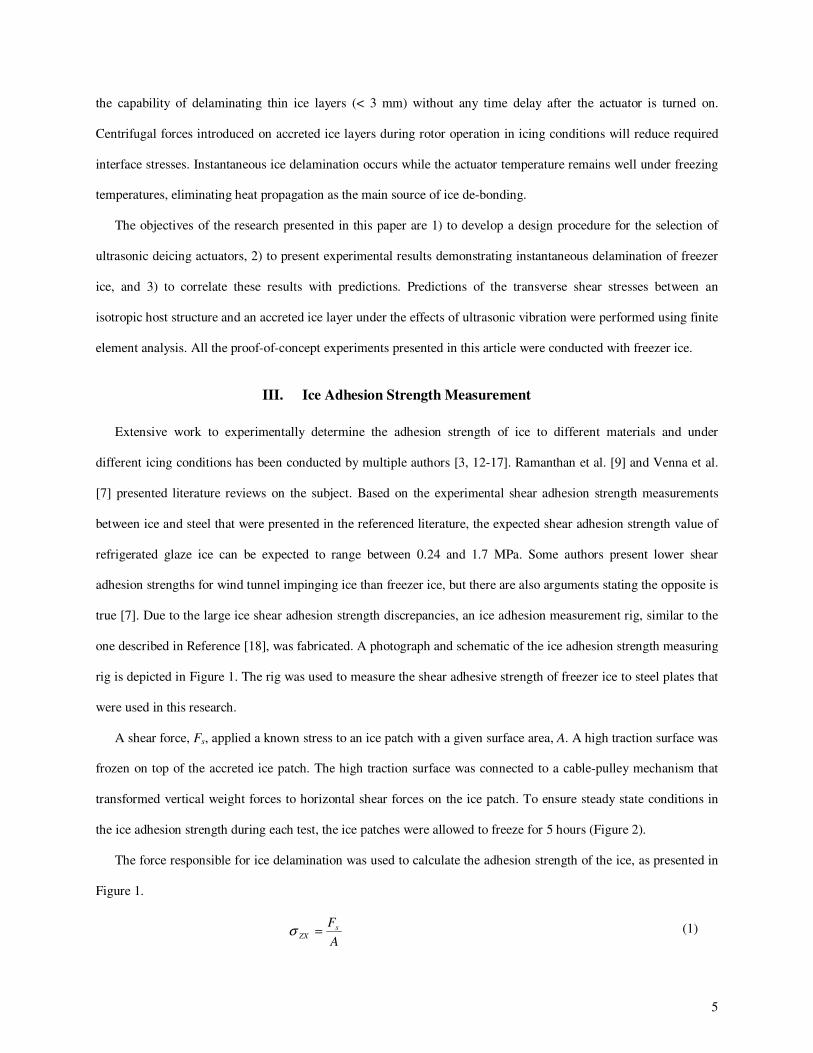
true [7]. Due to the large ice shear adhesion strength discrepancies, an ice adhesion measurement rig, similar to the
one described in Reference [18], was fabricated. A photograph and schematic of the ice adhesion strength measuring
rig is depicted in Figure 1. The rig was used to measure the shear adhesive strength of freezer ice to steel plates that
were used in this research.
A shear force, Fs, applied a known stress to an ice patch with a given surface area, A. A high traction surface was
frozen on top of the accreted ice patch. The high traction surface was connected to a cable-pulley mechanism that
transformed vertical weight forces to horizontal shear forces on the ice patch. To ensure steady state conditions in
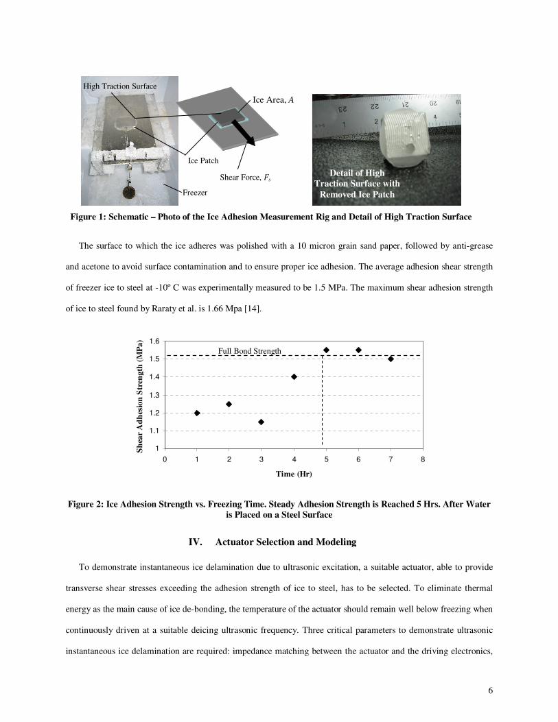
the ice adhesion strength during each test, the ice patches were allowed to freeze for 5 hours (Figure 2).
The force responsible for ice delamination was used to calculate the adhesion strength of the ice, as presented in
Figure 1.
A
FsZX =σ (1)
6
The surface to which the ice adheres was polished with a 10 micron grain sand paper, followed by anti-grease
and acetone to avoid surface contamination and to ensure proper ice adhesion. The average adhesion shear strength
of freezer ice to steel at -10º C was experimentally measured to be 1.5 MPa. The maximum shear adhesion strength
of ice to steel found by Raraty et al. is 1.66 Mpa [14].
1
1.1
1.2
1.3
1.4
1.5
1.6
0 1 2 3 4 5 6 7 8
Time (Hr)
Sh
ear
Ad
hes
ion
Str
eng
th (
MP
a)
Figure 2: Ice Adhesion Strength vs. Freezing Time. Steady Adhesion Strength is Reached 5 Hrs. After Water
is Placed on a Steel Surface
IV. Actuator Selection and Modeling
To demonstrate instantaneous ice delamination due to ultrasonic excitation, a suitable actuator, able to provide
transverse shear stresses exceeding the adhesion strength of ice to steel, has to be selected. To eliminate thermal
energy as the main cause of ice de-bonding, the temperature of the actuator should remain well below freezing when
continuously driven at a suitable deicing ultrasonic frequency. Three critical parameters to demonstrate ultrasonic
instantaneous ice delamination are required: impedance matching between the actuator and the driving electronics,
Figure 1: Schematic – Photo of the Ice Adhesion Measurement Rig and Detail of High Traction Surface
Detail of High
Traction Surface with
Removed Ice Patch
Ice Patch
Shear Force, Fs
High Traction Surface
Ice Area, A
Freezer
Full Bond Strength

7
the capability of the ultrasonic actuator to generate the required ice interface stresses, and the ability of the actuator
to remain under freezing conditions when driven at the required frequency and input voltage to promote ice
delamination.
A. Impedance Matching
In prior research described by the authors in Reference [10] regarding the effects of ultrasonic vibration on ice
accretion, instantaneous ice de-bonding was not experimentally observed despite predicted ultrasonic transverse
shear stresses exceeding the static adhesion strength of the ice layer. The lack of instantaneous ice de-bonding
observed in the results is explained by the lack of impedance matching during the experiments. Impedance matching
refers to the practice of attempting to make the output impedance of the power source equal to the input impedance
of the actuator to which it is ultimately connected to. This is done to maximize the power transfer and minimize
reflections from the load. Impedance matching is a partial solution to minimize input power requirements to
generate sufficient ice interface stresses to debond accreted ice.The forward power is denoted as the power sent to
the actuator systems, while the backward power is that power reflected from the system. To ensure that the voltage
reaching the actuator is effectively being converted into mechanical energy, minimum backward (or reflected)
power is desired. To create this condition, impedance matching between the source (amplifier) and the load (actuator
system) must occur at ultrasonic frequencies. This requirement is expressed by Equation 2, in where ZL is the
impedance of the load and ZS is the impedance of the source. The derivation of this requirement is found in
Reference [19].
SL
ZZ = (2)
Electrical impedance describes a measure of opposition to a continuous sinusoidal alternating current. Electrical
impedance provides information on the relative amplitudes and relative phase of the voltage potential and current in
an alternating circuit. Complex impedance is defined as the ratio of these quantities.
I
Z ~
~~ ϕ= (3)
In a direct current circuit there is no distinction between impedance and resistance. The symbol for impedance is
usually Z. θ is the phase of the impedance. Impedance is represented as a complex quantity, Z~
, as it is shown in
Equation 4:
θj
ZeZ =~
(4)
8
where the magnitude Z represents the ratio of the voltage amplitude to the current amplitude. The argument θ gives
the phase difference between voltage and current.
The meaning of electrical impedance can be understood by substituting it into Ohm's law (Equation 5).
θϕ jZeIZI
~~~~ == (5)
The magnitude of the impedance Z acts as a resistance, giving the drop in voltage amplitude across an impedance
value Z~
for a given current I~
.
The actuator must have an impedance value at the selected ultrasonic mode (mode able to create sufficient
interface stresses to delaminate accreted ice) such that is similar to that of the driving electronics, formed by an
amplifier and a signal generator. An impedance matching network able to vary the electronic impedance between 25
and 400 Ohms was used in this research. This network is part of an ultrasonic amplifier (AR 800) with a frequency
bandwidth ranging from 10 KHZ to 3 MHz.
B. Ice Interface Transverse Shear Stress
To select an ultrasonic actuator able to instantaneously delaminate accreted freezer ice, it is important to not only
ensure impedance matching between the actuator and the amplifier source, but to also provide interface shear
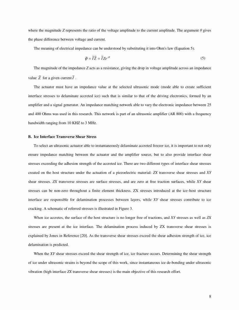
stresses exceeding the adhesion strength of the accreted ice. There are two different types of interface shear stresses
created on the host structure under the actuation of a piezoelectric material: ZX transverse shear stresses and XY
shear stresses. ZX transverse stresses are surface stresses, and are zero at free traction surfaces, while XY shear
stresses can be non-zero throughout a finite element thickness. ZX stresses introduced at the ice–host structure
interface are responsible for delamination processes between layers, while XY shear stresses contribute to ice
cracking. A schematic of referred stresses is illustrated in Figure 3.
When ice accretes, the surface of the host structure is no longer free of tractions, and XY stresses as well as ZX
stresses are present at the ice interface. The delamination process induced by ZX transverse shear stresses is
explained by Jones in Reference [20]. As the transverse shear stresses exceed the shear adhesion strength of ice, ice
delamination is predicted.
When the XY shear stresses exceed the shear strength of ice, ice fracture occurs. Determining the shear strength
of ice under ultrasonic strains is beyond the scope of this work, since instantaneous ice de-bonding under ultrasonic
vibration (high interface ZX transverse shear stresses) is the main objective of this research effort.
9
Figure 3: Stresses: σzx is Zero at the Elements Free Traction Surfaces, but Promotes Delamination between a
Host Structure and Accreted Ice Layer. The Ice Layer will also Undergoes σxy Stresses through its Thickness
(Stresses Responsible for Ice Cracking)
C. FEM Modeling
A commercial finite element package was used to model different PZT actuators attached to a 0.7 mm thick, 30.5
cm x 30.5 cm steel plate. A summary of the constitutive and equilibrium equations used by the software is presented
below.
Piezoelectric effects occur in noncentosymmetric crystals, such as PZT and quartz. Electric dipoles are generated
due to mechanical deformations. The converse effect (reverse piezoelectric effect) has been used in this research to
generate transverse shear stresses between a host structure and ice in order to de-bond the freezer ice.
The following summarized finite element method derivation is described in detail in references [21-25]. The
constitutive equations for piezoelectric materials under small field conditions are defined in Equation 6:
j
S
ijklkiji
Kkijkl
E
ijklij
ESeD
EeScT
ε+=
−= (6)
where D is the electric displacement vector (C/m2), S is the strain vector, E is the applied external electric field
vector (V/m), and T is the stress vector (N/m2). The elastic stiffness at constant electric field, cE, the piezoelectric
coupling, e, and the dielectric stiffness at constant strain, εS, are assumed to be constant, which is a reasonable
assumption for piezoelectric materials subjected to moderate electric fields (and therefore small deformations).
Newton’s law must be verified (Equation 7) for a uniform assumed displacement (Equation 8).
z
x
y
xyσ
z
x
y
xyσ zx
σ
ICE
zxσ
zxσ = 0
zxσ = 0
10
j
iji
x
T
t
u
∂
∂=
∂
∂2
2
ρ (7)
tiexUu
ωω),(= (8)
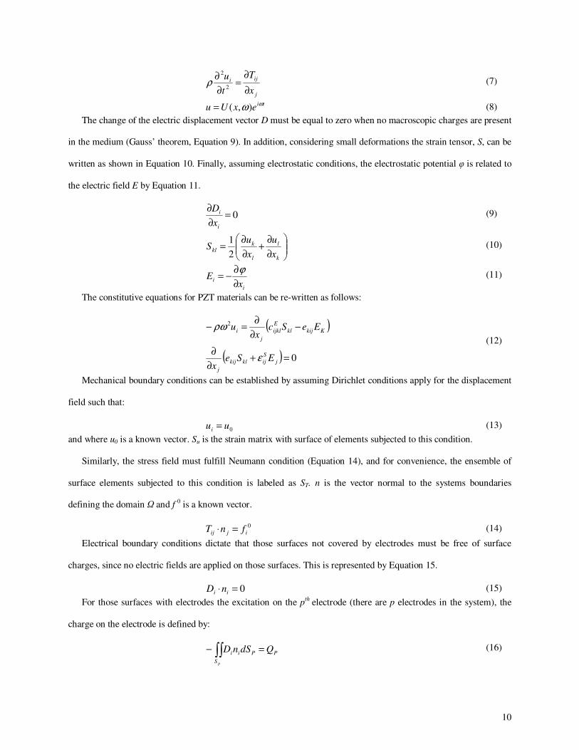
The change of the electric displacement vector D must be equal to zero when no macroscopic charges are present
in the medium (Gauss’ theorem, Equation 9). In addition, considering small deformations the strain tensor, S, can be
written as shown in Equation 10. Finally, assuming electrostatic conditions, the electrostatic potential φ is related to
the electric field E by Equation 11.
0=∂
∂
i
i
x
D (9)
∂
∂+
∂
∂=
k
l
l
kkl
x
u
x
uS
2
1 (10)
i
ix
E∂
∂−=
ϕ (11)
The constitutive equations for PZT materials can be re-written as follows:
( )
( ) 0
2
=+∂
∂
−∂
∂=−
j
S
ijklkij
j
Kkijkl
E
ijkl
j
i
ESex
EeScx
u
ε
ρω
(12)
Mechanical boundary conditions can be established by assuming Dirichlet conditions apply for the displacement
field such that:
0uui = (13)
and where u0 is a known vector. Su is the strain matrix with surface of elements subjected to this condition.
Similarly, the stress field must fulfill Neumann condition (Equation 14), and for convenience, the ensemble of
surface elements subjected to this condition is labeled as ST. n is the vector normal to the systems boundaries
defining the domain Ω and f 0 is a known vector.
0
ijij fnT =⋅ (14)
Electrical boundary conditions dictate that those surfaces not covered by electrodes must be free of surface
charges, since no electric fields are applied on those surfaces. This is represented by Equation 15.
0=⋅ ii nD (15)
For those surfaces with electrodes the excitation on the pth electrode (there are p electrodes in the system), the
charge on the electrode is defined by:
∫∫ =−
pS
PPii QdSnD (16)

11
The variation principle is used to define the functional over the domain and its boundaries. Using the system of
equations and boundary conditions defined above, a functional, Π, in where the mechanical and electrical energy of
the system (terms integrated in the domain Ω) are defined is identified (Equation 17).
( )
( ) ( )
( )
( ) ( )P
P
P
p
P
P S
Pj
S
ijkliklip
j
S
ijiiiklkl
S
Tii
S
uKkijkl
E
ijkljii
ikl
E
ijklij
QdSESen
dEEEeS
dSufdSEeScnuu
duScS
P
Tu
∑∑∫∫
∫∫∫
∫∫∫∫
∫∫∫
==
Ω
Ω
++−−
−Ω+−
−−−−−
−Ω−=∏
00
0
22
22
1
2
1
ϕεϕϕ
ε
ρω
(17)
The above functional can be rewritten in terms of finite elements by applying finite element methods. The finite
element method determines an approximate solution of the form:
∑=≈ iiaNww ˆ (18)
where Ni are acceptable shape functions that guarantee the continuity of the geometry between elements and that are
prescribed in terms of independent coordinates. ai are nodal parameters for the displacement, u, and electric
potential fields, φ.
The solution functions of the piezoelectric problem can be rewritten in terms of shape functions such that for
each element defined by n nodes, there is an electrical boundary condition, Ωe, where the electric field can be written
as:
Φ−= eBE φ (19)
where Φ is the vector of the nodal values of the electrostatic potential and
Te
i
e
i
e
ie
z
N
y
N
x
NB
∂
∂
∂
∂
∂
∂=ϕ
(20)
In the same fashion, for each element, the strain tensor is defined by Equation 21, where U is the vector of the
nodal values of the displacement.
UBSe
u−= (21)
T
e
i
e
i
e
i
e
i
e
i
e
i
e
i
e
i
e
i
e
u
x
N
y
N
z
N
x
N
z
N
y
N
y
N
z
N
x
N
B
∂
∂
∂
∂
∂
∂
∂
∂
∂
∂
∂
∂
∂
∂
∂
∂
∂
∂
=
000
000
000
(22)
12
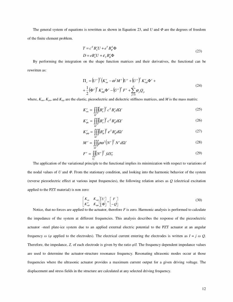
The general system of equations is rewritten as shown in Equation 23, and U and Φ are the degrees of freedom
of the finite element problem.
Φ+=
Φ+=
e
S
e
u
ETe
u
E
BUeBD
BeUBcT
ϕ
ϕ
ε (23)
By performing the integration on the shape function matrices and their derivatives, the functional can be
rewritten as:
( ) ( ) ( )
( ) ( ) ∑=
+−ΦΦ+
+Φ+−=Π
P
p
pp
eTeeeTe
ee
u
Teeee
uu
Te
e
QFUK
KUUMKU
0
2
2
1ϕ
ω
ϕϕ
ϕ
(24)
where, Kuu, Kφu, and Kφφ are the elastic, piezoelectric and dielectric stiffness matrices, and M is the mass matrix:
( )∫∫∫Ω
Ω=e
ee
u
ETe
u
e
uu dBcBK (25)
( )∫∫∫Ω
Ω=e
eeETe
u
e
u dBcBK ϕϕ (26)
( )∫∫∫Ω
Ω=e
eeSTee dBBK ϕϕϕϕ ε (27)
( )∫∫∫Ω
Ω=e
eeTee dNNM 2ρω (28)
( )∫∫=eTS
e
T
Tee fdSNF (29)
The application of the variational principle to the functional implies its minimization with respect to variations of
the nodal values of U and Φ. From the stationary condition, and looking into the harmonic behavior of the system
(reverse piezoelectric effect at various input frequencies), the following relation arises as Q (electrical excitation
applied to the PZT material) is non zero:
−=
Φ
Q
FU
KK
KKT
u
uuu
ϕϕϕ
ϕ (30)
Notice, that no forces are applied to the actuator, therefore F is zero. Harmonic analysis is performed to calculate
the impedance of the system at different frequencies. This analysis describes the response of the piezoelectric
actuator -steel plate-ice system due to an applied external electric potential to the PZT actuator at an angular
frequency ω (φ applied to the electrodes). The electrical current entering the electrodes is written as I = j ω Q.
Therefore, the impedance, Z, of each electrode is given by the ratio φ/I. The frequency dependent impedance values
are used to determine the actuator-structure resonance frequency. Resonating ultrasonic modes occur at those
frequencies where the ultrasonic actuator provides a maximum current output for a given driving voltage. The
displacement and stress fields in the structure are calculated at any selected driving frequency.

13
A 7.6 cm diameter, 2.5 mm thick PZT-4 disk was selected to impart in-plane stresses on the 0.7 mm thick, 30.5
cm x 30.5 cm steel plate. A schematic and photograph of the structure is illustrated in Figure 4.
Figure 4: Schematic and Photo of PZT-4 Disk Attached to a 30.5 cm x 30.5 cm x 0.71 mm Steel Plate
The actuator was selected because the predicted impedance of the actuator attached to the host structure was
calculated to be less than 400 Ohms at those frequencies corresponding with impedance lows. This impedance value
is in the range of the matching network of the power supply used during this research. Experimental and predicted
impedance values agree with errors of less than 3% at impedance lows, as it is illustrated in Figure 5.
Accreted ice layers were assumed to be isotropic and perfectly bonded to the steel plate (ice Young’s Modulus
9.1 GPa, ice density 900 Kgr/m3, and ice Poisson’s ratio 0.3). The steel plate and the ice layers are modeled with 20-
node 3D quadratic isotropic elements, while the piezoelectric actuator is modeled using 20-node 3D quadratic
piezoelectric elements (Figure 6).
Frequency (Hz)
Figure 5: Experimental and Predicted Impedance Curves of the PZT-4 Disk Bonded to a 30.5 cm x 30.5 cm
Steel Plate
Poling Direction +
_ 7.6 cm Diameter
2.5 mm Thick PZT
30.5 cm 30.5 cm
Steel Plate
Ice
Experimental
FEM
Imp
edan
ce (
Oh
ms)
Radial Disk Mode
14
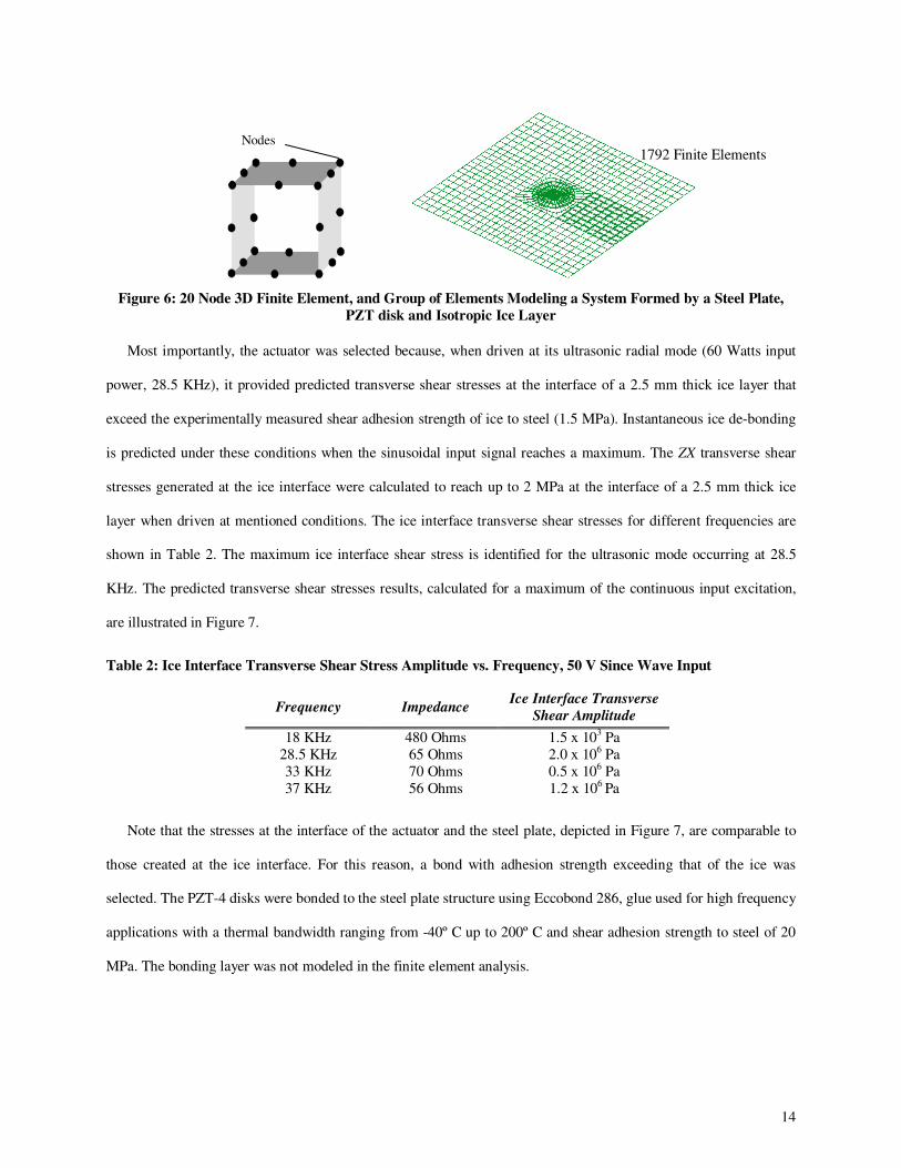
Figure 6: 20 Node 3D Finite Element, and Group of Elements Modeling a System Formed by a Steel Plate,
PZT disk and Isotropic Ice Layer
Most importantly, the actuator was selected because, when driven at its ultrasonic radial mode (60 Watts input
power, 28.5 KHz), it provided predicted transverse shear stresses at the interface of a 2.5 mm thick ice layer that
exceed the experimentally measured shear adhesion strength of ice to steel (1.5 MPa). Instantaneous ice de-bonding
is predicted under these conditions when the sinusoidal input signal reaches a maximum. The ZX transverse shear
stresses generated at the ice interface were calculated to reach up to 2 MPa at the interface of a 2.5 mm thick ice
layer when driven at mentioned conditions. The ice interface transverse shear stresses for different frequencies are
shown in Table 2. The maximum ice interface shear stress is identified for the ultrasonic mode occurring at 28.5
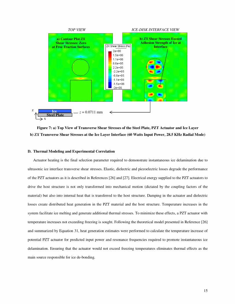
KHz. The predicted transverse shear stresses results, calculated for a maximum of the continuous input excitation,
are illustrated in Figure 7.
Note that the stresses at the interface of the actuator and the steel plate, depicted in Figure 7, are comparable to
those created at the ice interface. For this reason, a bond with adhesion strength exceeding that of the ice was
selected. The PZT-4 disks were bonded to the steel plate structure using Eccobond 286, glue used for high frequency
applications with a thermal bandwidth ranging from -40º C up to 200º C and shear adhesion strength to steel of 20
MPa. The bonding layer was not modeled in the finite element analysis.
Table 2: Ice Interface Transverse Shear Stress Amplitude vs. Frequency, 50 V Since Wave Input
Frequency Impedance Ice Interface Transverse
Shear Amplitude
18 KHz 480 Ohms 1.5 x 10³ Pa
28.5 KHz 65 Ohms 2.0 x 10⁶ Pa
33 KHz 70 Ohms 0.5 x 10⁶ Pa
37 KHz 56 Ohms 1.2 x 10⁶ Pa
Nodes 1792 Finite Elements
15
D. Thermal Modeling and Experimental Correlation
Actuator heating is the final selection parameter required to demonstrate instantaneous ice delamination due to
ultrasonic ice interface transverse shear stresses. Elastic, dielectric and piezoelectric losses degrade the performance
of the PZT actuators as it is described in References [26] and [27]. Electrical energy supplied to the PZT actuators to
drive the host structure is not only transformed into mechanical motion (dictated by the coupling factors of the
material) but also into internal heat that is transferred to the host structure. Damping in the actuator and dielectric
losses create distributed heat generation in the PZT material and the host structure. Temperature increases in the
system facilitate ice melting and generate additional thermal stresses. To minimize these effects, a PZT actuator with
temperature increases not exceeding freezing is sought. Following the theoretical model presented in Reference [26]
and summarized by Equation 31, heat generation estimates were performed to calculate the temperature increase of
potential PZT actuator for predicted input power and resonance frequencies required to promote instantaneous ice
delamination. Ensuring that the actuator would not exceed freezing temperatures eliminates thermal effects as the
main source responsible for ice de-bonding.
TOP VIEW ICE-DISK INTERFACE VIEW
Figure 7: a) Top View of Transverse Shear Stresses of the Steel Plate, PZT Actuator and Ice Layer
b) ZX Transverse Shear Stresses at the Ice Layer Interface (60 Watts Input Power, 28.5 KHz Radial Mode)
a) Contour Plot ZX
Shear Stresses: Zero
at Free Traction Surfaces
z = 0.0711 mm z Ice
Steel Plate x
b) ZX Shear Stresses Exceed
Adhesion Strength of Ice at
Interface
16
( )
( )( )
−+−
−
−++=
42
1
2
12
12122
12
121max
zzQTT
zz
TT
QTT
p
p
p
p
α
α (31)
where Qp, is the heat generation rate per unit volume in the PZT actuator,
V
P
Volume
PowerQ
p
p == (32)
and where the dissipative power consumption of the material, Pp, is
Z
VPp
2
2
= (33)
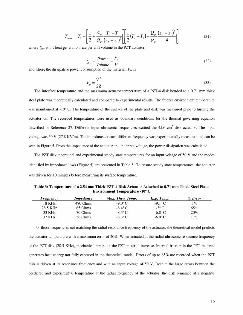
The interface temperature and the maximum actuator temperature of a PZT-4 disk bonded to a 0.71 mm thick
steel plate was theoretically calculated and compared to experimental results. The freezer environment temperature
was maintained at -100 C. The temperature of the surface of the plate and disk was measured prior to turning the
actuator on. The recorded temperatures were used as boundary conditions for the thermal governing equation
described in Reference 27. Different input ultrasonic frequencies excited the 45.6 cm2 disk actuator. The input
voltage was 50 V (27.8 KV/m). The impedance at each different frequency was experimentally measured and can be
seen in Figure 5. From the impedance of the actuator and the input voltage, the power dissipation was calculated.
The PZT disk theoretical and experimental steady state temperatures for an input voltage of 50 V and the modes
identified by impedance lows (Figure 5) are presented in Table 3. To ensure steady state temperatures, the actuator
was driven for 10 minutes before measuring its surface temperature.
For those frequencies not matching the radial resonance frequency of the actuator, the theoretical model predicts
the actuator temperature with a maximum error of 20%. When actuated at the radial ultrasonic resonance frequency
of the PZT disk (28.5 KHz), mechanical strains in the PZT material increase. Internal friction in the PZT material
generates heat energy not fully captured in the theoretical model. Errors of up to 65% are recorded when the PZT
disk is driven at its resonance frequency and with an input voltage of 50 V. Despite the large errors between the
predicted and experimental temperature at the radial frequency of the actuator, the disk remained at a negative
Table 3: Temperature of a 2.54 mm Thick PZT-4 Disk Actuator Attached to 0.71 mm Thick Steel Plate.
Environment Temperature -10º C
Frequency Impedance Max. Theo. Temp. Exp. Temp. % Error
18 KHz 480 Ohms -9.0º C -9.1º C 1%
28.5 KHz 65 Ohms -8.4º C -3º C 65%
33 KHz 70 Ohms -8.5º C -6.8º C 20%
37 KHz 56 Ohms -8.3º C -6.9º C 17%

17
temperature when a sinusoidal input signal of 50 V was applied. It can be concluded that the actuator rise in
temperature does not contribute to ice interface melting due to heat propagation.
An actuator configuration such that higher voltages to the actuator would be required (for similar or lower
impedance values) would imply an increase in the dissipated power, Pp, and therefore also increase the actuator
temperature. If the actuator temperature exceeded freezing, there would be uncertainties during experimental
correlations between ice delamination and transverse shear stress predictions, since thermal energy could be the
main factor de-bonding the ice layer.
V. Experimental Results
A. Instantaneous Ultrasonic Delamination of Freezer Ice
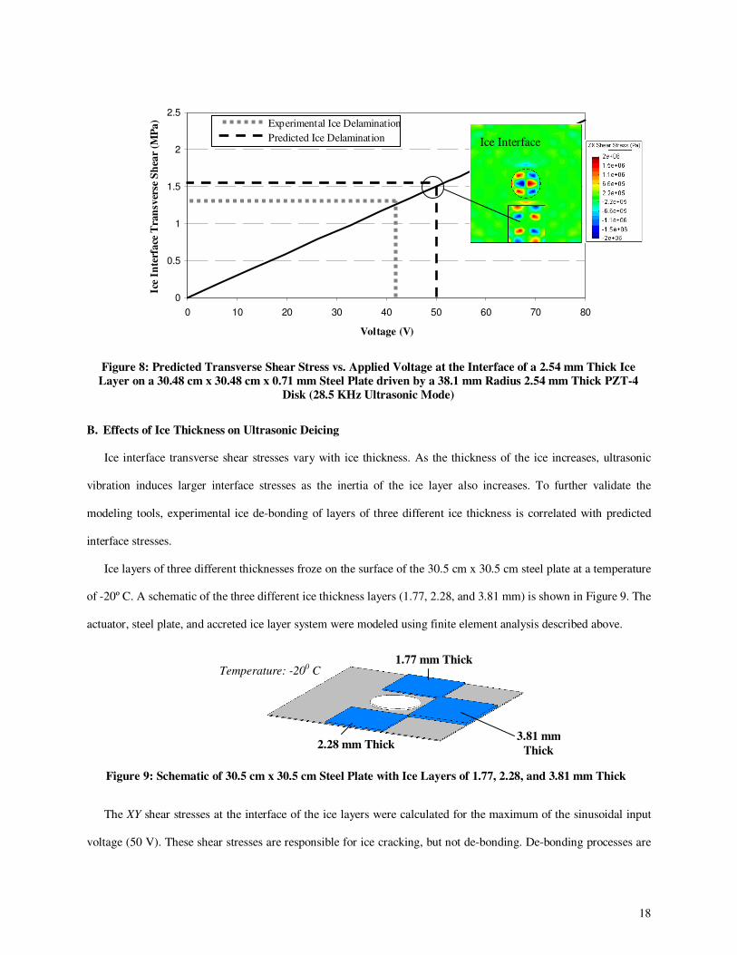
As presented in Figure 8, the predicted voltage amplitude required for the PZT-4 disk actuator to generate
interface transverse shear stresses on a 2.5 mm thick ice layer that exceed the shear adhesion strength of ice to steel
(1.5 MPa) is approximately 50 Volts (28.5 KHz actuator radial mode). Ice de-bonding is predicted when 28.5 KHz
and 50 V are applied to the disk actuator.
An ice layer 2.5 mm thick was allowed to accrete to the surface of the steel plate for 5 hours at a temperature of
-20º C. The steel plate was placed vertically so gravity forces would clearly show the ice falling after delamination.
The actuator was excited at its radial resonance (28.5 KHz), and accreted ice was instantaneously removed for input
voltages exceeding 43 V. Thus, the ultrasonic shear deicing method is experimentally validated. Thermocouples
placed on both the actuator and the steel plate showed temperatures of -180 C at the instant of ice de-bonding,
eliminating any concern about thermal propagation being a major effect on the ice de-bonding.
The actuator power consumption required to de-bond the freezer ice layer was measured to be 50 Watts or 0.077
W/cm2 (0.5 W/in2).
18
0
0.5
1
1.5
2
2.5
0 10 20 30 40 50 60 70 80
Voltage (V)
Ice
Inte
rfa
ce T
ran
sver
se S
hea
r (M
Pa
) Experimental Ice Delamination
Predicted Ice Delamination
Figure 8: Predicted Transverse Shear Stress vs. Applied Voltage at the Interface of a 2.54 mm Thick Ice
Layer on a 30.48 cm x 30.48 cm x 0.71 mm Steel Plate driven by a 38.1 mm Radius 2.54 mm Thick PZT-4
Disk (28.5 KHz Ultrasonic Mode)
B. Effects of Ice Thickness on Ultrasonic Deicing
Ice interface transverse shear stresses vary with ice thickness. As the thickness of the ice increases, ultrasonic
vibration induces larger interface stresses as the inertia of the ice layer also increases. To further validate the
modeling tools, experimental ice de-bonding of layers of three different ice thickness is correlated with predicted
interface stresses.
Ice layers of three different thicknesses froze on the surface of the 30.5 cm x 30.5 cm steel plate at a temperature
of -20º C. A schematic of the three different ice thickness layers (1.77, 2.28, and 3.81 mm) is shown in Figure 9. The
actuator, steel plate, and accreted ice layer system were modeled using finite element analysis described above.
The XY shear stresses at the interface of the ice layers were calculated for the maximum of the sinusoidal input
voltage (50 V). These shear stresses are responsible for ice cracking, but not de-bonding. De-bonding processes are
Figure 9: Schematic of 30.5 cm x 30.5 cm Steel Plate with Ice Layers of 1.77, 2.28, and 3.81 mm Thick
Ice Interface
Temperature: -200 C
2.28 mm Thick
1.77 mm Thick
3.81 mm
Thick
19
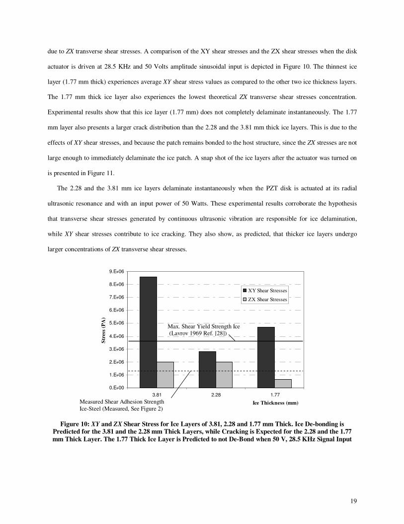
due to ZX transverse shear stresses. A comparison of the XY shear stresses and the ZX shear stresses when the disk
actuator is driven at 28.5 KHz and 50 Volts amplitude sinusoidal input is depicted in Figure 10. The thinnest ice
layer (1.77 mm thick) experiences average XY shear stress values as compared to the other two ice thickness layers.
The 1.77 mm thick ice layer also experiences the lowest theoretical ZX transverse shear stresses concentration.
Experimental results show that this ice layer (1.77 mm) does not completely delaminate instantaneously. The 1.77
mm layer also presents a larger crack distribution than the 2.28 and the 3.81 mm thick ice layers. This is due to the
effects of XY shear stresses, and because the patch remains bonded to the host structure, since the ZX stresses are not
large enough to immediately delaminate the ice patch. A snap shot of the ice layers after the actuator was turned on
is presented in Figure 11.
The 2.28 and the 3.81 mm ice layers delaminate instantaneously when the PZT disk is actuated at its radial
ultrasonic resonance and with an input power of 50 Watts. These experimental results corroborate the hypothesis
that transverse shear stresses generated by continuous ultrasonic vibration are responsible for ice delamination,
while XY shear stresses contribute to ice cracking. They also show, as predicted, that thicker ice layers undergo
larger concentrations of ZX transverse shear stresses.
0.E+00
1.E+06
2.E+06
3.E+06
4.E+06
5.E+06
6.E+06
7.E+06
8.E+06
9.E+06
3.81 2.28 1.77
Ice Thickness (mm)
Str
ess
(PA
)
XY Shear Stresses
ZX Shear Stresses
Figure 10: XY and ZX Shear Stress for Ice Layers of 3.81, 2.28 and 1.77 mm Thick. Ice De-bonding is Predicted for the 3.81 and the 2.28 mm Thick Layers, while Cracking is Expected for the 2.28 and the 1.77
mm Thick Layer. The 1.77 Thick Ice Layer is Predicted to not De-Bond when 50 V, 28.5 KHz Signal Input
Max. Shear Yield Strength Ice (Lavrov 1969 Ref. [28])
Measured Shear Adhesion Strength
Ice-Steel (Measured, See Figure 2)

20
Instantaneous Ice Delamination and Instantaneous Ice Delamination Full Ice Delamination does not
Cracking Occurred. Cracking is Observed
Figure 11: Experimental Ice De-Bonding and Fracture Patterns under Ultrasonic ZX and XY Shear Stresses
(28.5 KHZ, 50 V, -20º C). Patterns Agree with FEM Predictions
C. Ultrasonic Deicing of Airfoil Shaped Structures
FEM Modeling
Upon demonstrating instantaneous ice delamination due to ultrasonic transverse shear stresses on steel plates,
work efforts focused on using this approach to remove thin freezer ice layers from a more complex structure
representative of a rotor blade leading edge. An airfoil-shaped structure was fabricated out of 0.7 mm thick steel.
The airfoil-shaped structure was modeled using the finite elements methods previously presented. Two freezer
ice patches (2 mm x 23 mm x 95 mm) accreted to the top surface of the leading edge of the airfoil-shaped structure
were modeled as being perfectly bonded to the structure. The transverse shear stresses created at the interface of the
accreted ice layers were predicted. These ultrasonic transverse shear stresses were generated by two PZT-4 disk
actuators of 2.54 mm thickness and 38 mm radius. A schematic and finite elements used to model the system are
shown presented in Figure 12.
The predicted ultrasonic frequencies best suited to generate transverse shear stresses able to instantaneously de-
bond accreted ice would be those providing minimum impedance values, as seen in Figure 13. It is at these
frequencies (28.5 KHz, 30.5 KHz) that the ice interface transverse shear stress is maximized for a given input
voltage. Notice that at those frequencies away from impedance lows, the ice interface transverse shear stresses are
well under the adhesion strength of ice to steel (1.5 x 10⁶ Pa) for the given input voltage (100 V). At those
frequencies, ice delamination is not predicted.
Original Ice Shape
(1.77 mm Thick)
2.28 mm Thick Ice Layer
3.81 mm Thick
Ice Layer

21
Figure 12: Schematic and Finite Elements used to Model the Airfoil-Shaped Structure with Accreted Ice
Layers and PZT Actuators
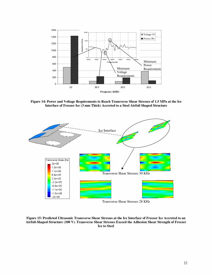
To promote ice delamination at frequencies not coinciding with ultrasonic modes, an increase in input voltage
would be required (500 V for the 23 KHz mode and 375 V for the 33.5 KHz mode). Even though there is an increase
in required input voltage to provide stresses able to delaminate the accreted ice layer, the related power would
decrease for an anti-resonance mode, as it is seen in Figure 14. These results assume that impedance matching
between the load and the driving electronics is enforced. The low power anti-resonance mode (33.5 KHz) could not
be triggered since the impedance of this mode exceeded matching network impedances For this reason, resonance
ultrasonic modes (28.5 and 30.5 KHz) are selected as candidates for experimental correlation with predicted ice
interface transverse shear stress values.
Modeling of the ice interface transverse shear stresses generated when the ultrasonic actuator is excited at its
impedance lows are presented in Figure 15. Both ultrasonic modes provide transverse shear stresses exceeding the
adhesion strength of ice when 100 V are applied.
10
100
1000
10000
20000 25000 30000 35000 40000 45000 50000
Frequency (Hz)
Imp
ed
am
ce (
Oh
ms)
Figure 13: Predicted Impedance for Airfoil-Shaped Structure with Two Disk Actuators and Two 3 mm Thick
Accreted Freezer Ice Layers. Impedance Low Ultrasonic Modes (28.5 and 30.5 KHz) are Suitable for Deicing
Max. σzx = 2.0 x 10⁶ Pa
30.5 cm
15.2 cm
4.3 cm
Max. σzx = 4.0 x 10⁵ Pa
Max. σzx = 3.0 x 10⁵ Pa
Max. σzx = 1.7 x 10⁶ Pa
2136 Elements
22
0
200
400
600
800
1000
1200
1400
1600
23 28.5 30.5 33.5
Frequency (KHZ)
Voltage (V)
Power (W)
Figure 14: Power and Voltage Requirements to Reach Transverse Shear Stresses of 1.5 MPa at the Ice
Interface of Freezer Ice (3 mm Thick) Accreted to a Steel Airfoil Shaped Structure
Figure 15: Predicted Ultrasonic Transverse Shear Stresses at the Ice Interface of Freezer Ice Accreted to an
Airfoil-Shaped Structure (100 V). Transverse Shear Stresses Exceed the Adhesion Shear Strength of Freezer Ice to Steel
Transverse Shear Stresses 30 KHz
Transverse Shear Stresses 28 KHz
Ice Interface
Minimum Power
Requirements Minimum Voltage
Requirements
10
100
1000
10000
20000 25000 30000 35000 40000 45000 50000
Frequency (Hz)
Imp
ed
am
ce (
Oh
ms)
23
Experimental Correlation
Two ultrasonic disk actuators were bonded to the bottom of a steel airfoil shaped structure of same dimensions
as the one shown in Figure 12. Two ice patches (~3 mm thick) were frozen on the top surface at a temperature of
-20° C.
In these set of experiments, the actuators were excited at 28 and 30.5 KHz ultrasonic modes respectively (200
Watts input power). These two ultrasonic modes were selected because the impedance of the system was in the
range of the available impedance matching networks. The ultrasonic excitation provided localized ice interface
stresses exceeding the adhesion strength of ice to steel. These stresses weakened the ice locally and instantaneous
ice delamination was observed at certain locations of the ice patch. Subsequent complete ice delamination occurred
~2 second later for both ultrasonic modes. Ice delamination was not observed when 200 watts and other modes with
impedances under 400 Ohms were triggered. These experimental results demonstrate the potential use of ultrasonic
excitation in high curvature areas such as helicopter leading edge protection caps.
VI. Conclusions
Based on the results of this investigation, the following conclusions are made:
1) It was predicted and validated experimentally that instantaneous delamination between ice and isotropic plates
representative of helicopter leading edge protection caps is possible using ultrasonic excitation (27 KHz – 32 KHz),
as transverse shear stresses generated at the ice interface exceed the adhesion strength of the ice.
2) In the presented cases, instantaneous ice delamination is not due to thermal processes related to ultrasonic
vibration, as the PZT material remained well under freezing temperatures at the moment of ice de-bonding.
3) The power required to instantaneously de-bond freezer ice layers (ranging between 2 mm and 4 mm in
thickness) accreted to a 0.7 mm thick steel plate was measured to be 0.05 W/cm2 (0.34 W/in2).
4) Impedance matching between the load (actuator) and driving electronics enhances instantaneous ice
delamination using piezoelectric actuators, since this condition maximizes input power conversion into mechanical
ice debonding stresses.
5) Ultrasonic ice interface transverse shear stresses can be predicted using finite element methods that model the
actuator, host structure and accreted ice layer.
24
6) Ice interface transverse shear stresses are dependent on the accreted ice thickness. At a constant actuation
input, thicker ice layers undergo larger transverse shear stresses. A 50 Watts ultrasonic excitation input provided by
a 2.5 mm thick, 7.6 cm diameter PZT-4 disk (28.5 KHz radial resonance frequency) is able to instantaneously de-
bond freezer ice layers as thin as 2 mm.
7) Freezer ice formed on an airfoil-shaped isotropic structure can also be removed by ultrasonic excitation that
provides interface transverse shear stresses exceeding the adhesion strength of the ice to the substrate. The required
input power and actuator density had to be increased with respect to plate configurations due to the higher structure
stiffness of the airfoil-shape configuration (0.2 W/cm2, 1.4 W/in2).
Studies on the effect of ultrasonic excitation on impinging ice are suggested to further demonstrate the ability of
ultrasonic excitation to de-ice realistic helicopter blade structures under icing conditions.
Acknowledgments
The authors would like to thank Bell Helicopters, a Textron Company, and the US Army for sponsoring this
research. This research is partially funded by the Government under Agreement No. W911W6-06-2-0008, and by
FBS Worldwide Inc. thanks to Aviation Applied Technology Directorate Phase I SBIR contract No. W911W6-08-
C-0019. The U.S. Government is authorized to reproduce and distribute reprints notwithstanding any copyright
notation thereon. The views and conclusions contained in this document are those of the authors and should not be
interpreted as representing the official policies, either expressed or implied, of the U.S. Government.
References
1. Gent, R.W., Dart, N.P., and Candsdale, J.T., “Aircraft Icing,” Philosophical Transactions of the Royal Society of London Series A, Vol. 358, 2000, pp. 2873 – 2911.
2. Coffman, H.J., “Helicopter Rotor Icing Protection Methods,” Journal of the American Helicopter Society, Vol. 32, No. 2, April 1987, pp. 34 – 39.
3. Scavuzzo R.J., Chu M.L, Kellackey C.J., “Impact Ice Stress in Rotating Airfoils,” Journal of Aircraft, Vol. 28, No. 7, Jul 1991, pp. 450 – 455.
4. Zumwalt, G. W., “Icing Tunnel Tests of Electro-Impulse De-icing of Engine Inlet and High-Speed Wings,” AIAA 23rd Aerospace Science Meeting, January 1985. Reno, Nevada.
5. Reinmann, J. J., Shaw, R. J., and Ranaudo, R. J., “NASA’s Program on Icing Research and Technology,” Proceedings of the Symposium on Flight in Adverse Environmental Conditions, Kluwer Publishers, Norwell, MA, May 1989, pp. 73 – 78.
6. Martin, C. A, and Putt, J. C., “Advanced Pneumatic Impulse Ice Protection System (PIIP) for Aircraft,” Journal of Aircraft, Vol. 29, No 4, 1992, pp. 714 – 716.
7. Venna, S. V., Lin Y., Botura, G., “Piezoelectric Transducer Actuated Leading Edge De-Icing with Simultaneous Shear and Impulse Forces,” Journal of Aircraft, Vol. 44, No. 2, March–April 2007, pp. 510 – 515.
8. Palacios, J., L., Smith, E., C., “Dynamic Analysis and Experimental Testing of Thin-Walled Structures Driven By Shear Tube Actuators,” 46th AIAA/ASME/ASCE/AHS/ ASC Structures, Structural Dynamics & Materials, AIAA-2005-2112, Austin, Texas, April 2005, pp. 3862 – 3875.
25
9. Ramanathan, S., Varadhan, V. V., and Varadhan, V. K., “De-Icing of Helicopter Blades Using Piezoelectric Actuators,” Smart Structures and Materials 2000: Smart Electronics and MEMS, SPIE Publishing, Seattle, WA, March 2002, pp. 354 – 363.
10. Palacios J., Smith, E., Rose J., Gao, H., “Ultrasonic Shear Wave Anti-Icing System for Helicopter Rotor Blades,” 62nd Annual Forum Proceedings - American Helicopter Society, Phoenix, Arizona, May 2006, p 1492 – 1502.
11. Lemont, H. E., and Upton, H., “Vibratory Ice Protection for Helicopter Rotor Blades,” USAAMRDL-TR-77-29, June 1978.
12. Chu M.C., and Scavuzzo R.J., “Adhesive Shear Strength of Impact Ice”, AIAA Journal, Vol. 29, No. 11, November, 1991, pp 1921 – 1926.
13. Bascom W.; Cottington R.; Singleterry C., “Ice Adhesion to Hydrophilic And Hydrophobic Surfaces,” Journal of Adhesion, Vol. 1, Oct 1969, pp 246 – 63.
14. Raraty, L., Tabor., “The adhesion and Strength Properties of Ice,” Royal Society -- Proceedings, Vol. 245, No. 1241, June 1958, pp 184 – 201.
15. Stallabrass, J., Price., R., “On the Adhesion of Ice to Various Materials,” Canada National Research Council -- Aeronautical Report, July 1962, pp 199 – 219.
16. Jellinek, H., “Bonding of Flat Ice Surfaces,” United States Snow, Ice and Permafrost Research Establishment --
Research Reports, July, 1960. 17. Terashima, T., “Comparative Experiments on Various Adfreeze Bond Strength Tests between Ice and Metals,”
Computational Methods in Contact Mechanics III, Edited by Aliabadi, M., Computational Mechanics Publications, 1997, pp 205 – 215.
18. Blackburn, C., Laforte, C., Laforte, J. L., “Apparatus for Measuring the Adhesion Force of a Thin Ice Sheet on a
Substrate,” Anti-icing Materials International Laboratory and University of Quebec at Chicoutimi., June 2000. 19. Someda, C., “Electromagnetic Waves,” Chapman and Hall, London 1998, pp 284 – 295. 20. Jones, R., “Mechanics of Composite Materials,” Taylor and Francis, 1999. 21. Sirohi, J., Chopra, I., “Fundamental Understanding of Piezoelectric Strain Actuators,” J. Intelligent Material Systems
and Structures., 2000, 11(4), 246 – 257. 22. Jarng, S., “Comparison of Barrel-Stave Sonar Transducer Simulation Between a Coupled FE-BEM and ATILA,” IEEE
Sensors Journal, Vol. 3, No. 4, 2003. 23. Uchino, K., FEM and Micromechatronics with ATILA Software, Taylor & Francis, Inc., May 2008.
24. Magsoft Corporation, ATILA Finite Element Code for Piezoelectric and Magnetostrictive Transducer Modeling
Version 5.03 User’s Manual, Acoustics Laboratory, Inst. Sup. D’Electron. Du Nord, MAGNASOFT Co., Sept. 1993. 25. A. Safari, E.K. Akdo˘gan (eds.) Piezoelectric and Acoustic Materials for Transducer Applications, Chapter 12 by
Hladky-Hennion, A., and Dubus, b., p 241 – 257, Springer Science&Business Media, LLC 2008. 26. Zhou, S., Liang, C., Rogers, A., “Integration and Design of Piezoelectric Elements in Intelligent Structures,” Journal of
Intelligent Material Systems and Structures, Vol. 6, November 1995. 27. Zheng, J., Takahashi, S., Uchino, K., Vries, J., “Heat Generation in Multilayer Piezoelectric Actuators,” America
Ceramic Society, 1996, pp. 3191 – 3198.
28. Lavrov, V.. “Deformation and strength of ice,” Gidrometeorologichesko Isdatel'stvo, Leningrad, U.S.S.R. NSF
Translation CTT 70-50130, National Science Foundation, Washington, DC, 1969.