Embed Size (px)
Citation preview
Instantaneous mechanical fastening of quasi-isotropic CFRP laminates by a self-piercing rivet
Masahito Ueda a,*, Sotaro Miyake a, Hiroyuki Hasegawa b, Yoshiyasu Hirano c
a Nihon University
1-8-14 Kanda-surugadai, Chiyoda, Tokyo 101-8308, Japan
E-mail: [email protected]
Tel & Fax: +81-3-3259-0746 b Fukui Byora Co., Ltd.
3-2-2 Higashi-Machi, Daishoji, Kaga, Ishikawa 922-0816, Japan c Japan aerospace exploration agency
6-13-1 Oosawa, Mitaka, Tokyo 181-0015, Japan
*Corresponding author
ABSTRACT
A modified self-piercing rivet (SPR) has been proposed to mechanically fasten CFRP laminates. The
modified SPR consists of a rivet body and two flat washers. The two flat washers were used to suppress
delamination in the CFRP laminates at the point of piercing. The advantages of the modified SPR for fastening
CFRP laminates are instantaneous process time and low cost. Any pretreatments such as surface treatments or hole
drilling are not required. In this study, the viability of the modified SPR for a quasi-isotropic CFRP laminate was
investigated by tensile and fatigue tests on the single lap joints. The experimental results showed that the tensile
strength of a modified SPR joint was slightly higher than a bolted joint. In tension-tension fatigue tests, a fatigue
limit at Nf=107 cycles was about 50 % of the tensile joint strength. Experimental results showed that the modified
SPR was one of the promising fasteners for future mass-production CFRP automobiles.
Keywords: CFRP, Joint, Fastener, Strength, Fatigue
1. Introduction
Because of the strong demand for weight reduction in mass produced automobiles, structural steel
components are progressively being replaced by carbon fiber reinforced plastic (CFRP) laminates. Spot welding is
in general use in steel structures as a low cost and instantaneous joint. There is, however, no such instantaneous
joining technique for CFRP laminates, which is inhibiting the wide application of CFRP laminates in automotive
structures.
Adhesive is generally used to fasten CFRP laminates. However, this is a problem for mass production.
Lengthy times are required for curing and additional surface treatment, which increase manufacturing cost. The
effects of temperature, humidity and strain rate on the mechanical properties need careful consideration [1-3].
This document is provided by JAXA.
Mechanical fasteners such as rivets or bolts are also used to fasten CFRP laminates [4]. This, however,
requires hole drilling before fastening, which takes time and requires care to prevent damage in the CFRP laminates
[5, 6]. Tool life becomes shorter for CFRP laminates than for steel fabrication [7]. Therefore, low cost and instant
fasteners for CFRP laminates are required to resolve the problems of the adhesives and the conventional rivet or
bolt fasteners.
A self-piercing rivet (SPR) has been adopted to fasten metal sheets [8, 9]. Hole drilling is unnecessary in
the fastening process, which drastically reduces processing time. However, there are no reports on the fastening of
the CFRP laminates by SPRs since they may easily cause damage such as delamination at the points of piercing. In
this study, a modified SPR is proposed to minimize delamination at the points of piercing. Instantaneous
mechanical fastening of quasi-isotropic CFRP laminates was performed using the modified SPR. The viability of
the modified SPR for CFRP laminates was discussed from the experimental results of quasi-static tensile and
fatigue tests on single lap joints.
2. Modified SPR
2.1 Materials and configuration
Fig. 1 shows the configuration of a modified SPR. The modified SPR consists of a rivet body and two flat
washers. Materials of the rivet body and the flat washers are SCM435 and S45C respectively. SCM435 was used
because it has been in use for the conventional SPR on metal sheets. The corrosion problem between the rivet body
and a CFRP needs to be resolved by surface coating or by changing the material of the rivet body, which is beyond
the scope of this study.
2.2 Fastening process
Since the rivet body pierces the CFRP laminates in the fastening process, initial hole drilling is not
required. However, damage to the CFRP laminates such as delamination due to the piercing process needs to be
suppressed because it propagates under fatigue load, which drastically reduces the acceptable mechanical properties
of CFRP laminates. In fastening using the modified SPR, delamination is suppressed by applying pressure to the
CFRP laminates during piercing.
Figs. 2a and 2b show cross-sectional drawings of CFRP laminates before fastening (before piercing) and
after fastening (after piercing). The upper and lower flat washers (1) and (2) are placed on the upper and lower
supporting dies (3) and (4). After positioning the supporting dies at a fastening point, the upper and lower
supporting dies are pressed against the CFRP laminates. Since the pressure needs to be applied very close to the
piercing hole to prevent delamination, two flat washers were used. Therefore, pressure was applied by the two
supporting dies through the two flat washers. Maintaining the pressure, the rivet body pierced the CFRP laminates.
Chopped CFRP at the rivet body due to the piercing was discharged through the lower supporting die. After
piercing, the cutting tip of the rivet body was curled by the lower supporting die, to complete the fastening process.
Fastening using the modified SPR requires no initial hole drilling which enables instant fastening by means of an
automatic riveting machine.
The clearance between the outer diameter of the rivet body and inner diameter of the washers affects the
suppression of delamination in the piercing process. There is a curvature (of radius R) at the neck part of the rivet
This document is provided by JAXA.
body to reduce stress concentration (see Fig. 1a). For the upper flat washer, the chamfer (of length C1) was
machined at the inner corner (see Fig. 1b). The chamfered length is slightly larger than the curvature radius on the
rivet, by which the clearance between the outer diameter of the rivet body and the inner diameter of the upper flat
washers was minimized. For the lower flat washer, the inner diameter should be almost the same as the outer
diameter of the rivet body although this depends on the positioning accuracy and stiffness of the rivet body. In this
study, 5.0 mm for the outer diameter of the rivet body and 5.1 mm for the inner diameter of the flat washers were
selected. The diameter and thickness of the rivet body should be properly selected according to CFRP laminates to
prevent bucking of the rivet body in the piercing process.
In this study, the fastening process was divided into two steps to measure the applied load to the CFRP
laminates. First step was a piercing process of the CFRP laminates by the rivet body. Second step was a swaging
process of the cutting tip. Both processes were performed using a riveting machine under control of displacement.
Figs. 3a and 3b show load-time curves in the piercing and swaging process. The upper and lower
supporting dies were pressed against the CFRP laminates at 6.5 kN. Maximum load in the piercing process was
about 18 kN which included 6.5kN pre-loading by the supporting dies. Then, swaging of the cutting tip was
performed. Maximum load in the swaging process was 38 kN. The load in the thickness direction has been
applying to the CFRP laminates by the rivet body through the flat washers after the fastening.
2.3 Damages in CFRP laminate due to piercing
Fig. 4a shows a cross-sectional photograph of quasi-isotropic CFRP laminates after fastening using the
modified SPR. Fig. 4b shows schematic drawing of Fig. 4a. The material and stacking sequence of the CFRP
laminates are shown in Section 3.1. Dragging of the plies due to the piercing was found around the piercing hole.
Delamination was not apparent using visual inspection because the delaminated plies were clamped together by the
modified SPR. It may be impossible topologically to drag the plies without separation of the plies, which indicates
delamination in the dragging area.
The modified SPR was removed after the fastening to measure the delamination size. The delamination in
the CFRP laminates was measured by means of ultrasonic inspection (SDS-5400R, Krautkramer). Fig. 5 shows
C-scan images of the delamination in the CFRP laminates and the external appearances. The size of the
delamination due to the piercing was much smaller than the diameter of the flat washer. Delamination can be
adequately suppressed by applying pressure to the CFRP laminates in the piercing process.
3. Material and specimen configuration
3.1 CFRP laminate
Quasi-isotropic CFRP laminates were made using a unidirectional prepreg tape in the autoclave molding
method. The prepreg tape used in this study was T800SC/#2592 produced by Toray Industries. The stacking
sequence was [452/02/-452/902]s. After curing the CFRP laminates, it was cut into a rectangular shape of 135 mm
long and 36 mm wide using a diamond cutting machine. The thickness of the laminate was 1.6 mm. The fiber
volume fraction was about 65 %.
3.2 Single lap joint
This document is provided by JAXA.
The configuration of a single lap joint for quasi-static tensile and fatigue tests is shown in Fig. 6, which
was followed by ASTM D5961 except the thickness. A bolted joint with the same configuration was also prepared
to compare the joint strengths. For the bolted joint, initially a 5.1 mm hole was drilled and the laminates were then
jointed using an M5 bolt and nut. The material of the bolt was SCM435. The bolt had a smoothed circular cylinder
part which was in contact with the hole through the CFRP laminates. The bolt and nut were tightened using only
fingers so that pressure was not applied to the CFRP laminates. The washers used for the modified SPR joint were
also used for the bolted joint.
4. Quasi-static tensile test
4.1 Experimental procedure
Quasi-static tensile tests of the single lap joints were performed using a universal testing machine
(AG-IS150kN, Shimadzu). Crosshead speed was 1.0 mm/min.
4.2 Results and discussion
Fig. 7 shows the load-displacement curves of the two single lap joints made by a modified SPR and a bolt.
The tensile tests were performed three times for each joint, in which almost the same load-displacement curves
were obtained. The joint stiffness was relatively higher for the modified SPR joint than for the bolted joint. The
average maximum loads PU in the three tests were 8.0 kN for the modified SPR joint and 7.2 kN for the bolted joint.
A slightly higher maximum load was observed for the modified SPR joint than for the bolted joint. Clearance
between the fastener and the hole was smaller for the modified SPR joint than the bolted joint since the modified
SPR pierces into the CFRP laminate without drilling. The contact area was, therefore, larger for the modified SPR
joint, which increased the joint stiffness and the joint strength [10]. Load was suddenly dropped for the bolted joint
just after reaching maximum load. By contrast, the maximum load for the modified SPR joint was retained for a
period of time. The load in the thickness direction was applied to the CFRP laminates by the rivet body because of
the swaging process of the cutting tip. The relatively high constraint in the thickness direction prevented
catastrophic failure of the CFRP laminates, enabling the modified SPR joint to retain the maximum load for a
period of time [11-13].
Fig. 8 shows the external appearance of the single lap joints after tensile tests. The tensile tests were
continued until the joints separated. The failure mode was bearing failure for both joints as shown in Fig. 9a. Fig.
9b shows damage progress of the bearing failure. Since the thickness was relatively thin, the rivet body was pulled
out from the CFRP laminate as a result of the bearing failure. Previous studies indicate bearing failure for the
specimen configuration [13, 14].
5 Fatigue test
5.1 Experimental procedure
Fatigue tests on the single lap joints were performed by a hydraulic fatigue testing machine (8802,
Instron). The stress ratio was fixed to R=0.1. The maximum load Pmax was changed to 90, 80, 70, 60, 55, 50, 40 %
of the static tensile strength PU. The test frequency was 2 Hz. Fatigue tests were performed only for the modified
SPR jointed CFRP laminates.
This document is provided by JAXA.
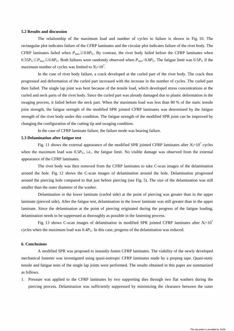
5.2 Results and discussion
The relationship of the maximum load and number of cycles to failure is shown in Fig. 10. The
rectangular plot indicates failure of the CFRP laminates and the circular plot indicates failure of the rivet body. The
CFRP laminates failed when Pmax≧0.8PU. By contrast, the rivet body failed before the CFRP laminates when
0.55PU≦Pmax≦0.8PU. Both failures were randomly observed when Pmax=0.8PU. The fatigue limit was 0.5PU if the
maximum number of cycles was limited to Nf=107.
In the case of rivet body failure, a crack developed at the curled part of the rivet body. The crack then
progressed and deformation of the curled part increased with the increase in the number of cycles. The curled part
then failed. The single lap joint was bent because of the tensile load, which developed stress concentrations at the
curled and neck parts of the rivet body. Since the curled part was already damaged due to plastic deformation in the
swaging process, it failed before the neck part. When the maximum load was less than 80 % of the static tensile
joint strength, the fatigue strength of the modified SPR jointed CFRP laminates was determined by the fatigue
strength of the rivet body under this condition. The fatigue strength of the modified SPR joint can be improved by
changing the configuration of the cutting tip and swaging condition.
In the case of CFRP laminate failure, the failure mode was bearing failure.
5.3 Delamination after fatigue test
Fig. 11 shows the external appearance of the modified SPR jointed CFRP laminates after Nf=107 cycles
when the maximum load was 0.5PU, i.e., the fatigue limit. No visible damage was observed from the external
appearance of the CFRP laminates.
The rivet body was then removed from the CFRP laminates to take C-scan images of the delamination
around the hole. Fig. 12 shows the C-scan images of delamination around the hole. Delamination progressed
around the piercing hole compared to that just before piercing (see Fig. 5). The size of the delamination was still
smaller than the outer diameter of the washer.
Delamination in the lower laminate (curled side) at the point of piercing was greater than in the upper
laminate (pierced side). After the fatigue test, delamination in the lower laminate was still greater than in the upper
laminate. Since the delamination at the point of piercing originated during the progress of the fatigue loading,
delamination needs to be suppressed as thoroughly as possible in the fastening process.
Fig. 13 shows C-scan images of delamination in modified SPR jointed CFRP laminates after Nf=107
cycles when the maximum load was 0.4PU. In this case, progress of the delamination was reduced.
6. Conclusions
A modified SPR was proposed to instantly fasten CFRP laminates. The viability of the newly developed
mechanical fastener was investigated using quasi-isotropic CFRP laminates made by a prepreg tape. Quasi-static
tensile and fatigue tests of the single lap joints were performed. The results obtained in this paper are summarized
as follows.
1. Pressure was applied to the CFRP laminates by two supporting dies through two flat washers during the
piercing process. Delamination was sufficiently suppressed by minimizing the clearance between the outer
This document is provided by JAXA.
diameter of the rivet body and inner diameter of the washers. The CFRP laminates were mechanically fastened
instantaneously without the need to drill a hole.
2. The modified SPR joint showed greater joint stiffness and strength than the bolted joint. The maximum load
was retained for a period of time for the modified SPR joint although the load was suddenly dropped for the
bolted joint. The failure mode of the joints was bearing failure.
3. The fatigue limit of the modified SPR jointed CFRP laminates was 50 % of the static tensile joint strength. The
rivet body failed prior to the CFRP laminates when the maximum load was lower than 80 % of the static tensile
joint strength. By contrast, the CFRP laminates failed prior to the rivet body when the maximum load was
higher than 80 % of the static tensile joint strength.
4. Delamination in the modified SPR jointed CFRP laminates after the fatigue test of 107 cycles was smaller than
the diameter of the washer when the maximum load was less than 50 % of the tensile joint strength.
References
1. Ashcroft IA, Hughes DJ, Shaw SJ, Wahab MA, Crocombe A. Effect of temperature on the quasi-static strength
and fatigue resistance of bonded composite double lap joints. Journal of adhesives 2001; 75(1): 61-68.
2. Ferreira JAM, Reis PN, Costa JDM, Richardson MOW. Fatigue behaviour of composite adhesive lap joints.
Composites Science and Technology 2002; 62(10-11): 1373-1379.
3. Casas-Rodriguez J.P, Ashcroft I.A, Silberschmidt V.V. Damage in adhesively bonded CFRP joints: Sinusoidal
and impact-fatigue. Composites Science and Technology 2008; 68(13):2663-2670.
4. Thoppul S. D, Finegan J, Gibson R.F. Mechanics of mechanically fastened joints in polymer–matrix composite
structures – A review. Composites Science and Technology 2009; 69(3-4): 301-329.
5. Khashaba U.A, El-Sonbaty I.A, Selmy A.I, Megahed A.A. Machinability analysis in drilling woven
GFR/epoxy composites: Part I – Effect of machining parameters. Composites: Part A 2010; 41(3): 391-400.
6. Durão Luís Miguel P, Gonçalves Daniel J.S, Tavares João Manuel R.S, de Albuquerque Victor Hugo C.,
Aguiar Vieira A., Torres Marques A. Drilling tool geometry evaluation for reinforced composite laminates.
Composite Structures 2010; 92 (7): 1545-1550.
7. Iliescu D, Gehin D, Gutierrez M.E, Girot F. Modeling and tool wear in drilling of CFRP. International Journal
of Machine Tools and Manufacture 2010; 50(2): 204–213.
8. Abe Y, Kato T, Mori K. Self-piercing riveting of high tensile strength steel and aluminium alloy sheets using
conventional rivet and die. Journal of Materials Processing Technology 2008; 209(8): 3914-3922.
9. Hoang NH, Porcaro R, Langseth M, Hanssen AG. Self-piercing riveting connections using aluminium rivets.
International Journal of Solids and Structure 2010; 47(3-4): 427-439.
10. McCarthy MA, Lawlor VP, Stanley WF, McCarthy CT. Bolt-hole clearance effects and strength criteria in
single bolt, single lap, composite joints. Composites Science and Technology 2002; 62(10-11): 1415-1431.
11. Stockdale J.H., Matthews F.L. The effect of clamping pressure on bolt bearing loads in glass fibre-reinforced
plastics. Composites 1976; 7(1): 34-38.
12. Collings TA. The strength of bolted joints in multi-directional CFRP laminates. Composites 1977; 8(1): 43-54.
This document is provided by JAXA.

13. Kretsis G, Matthews FL. The strength of bolted joints in glass fibre/epoxy laminates. Composites 1985; 16(2):
2-105.
14. Valenza A., Fiore V. Failure map of composite laminate mechanical joint. Journal of Composite Materials
2007; 41(8): 951-964.
This document is provided by JAXA.
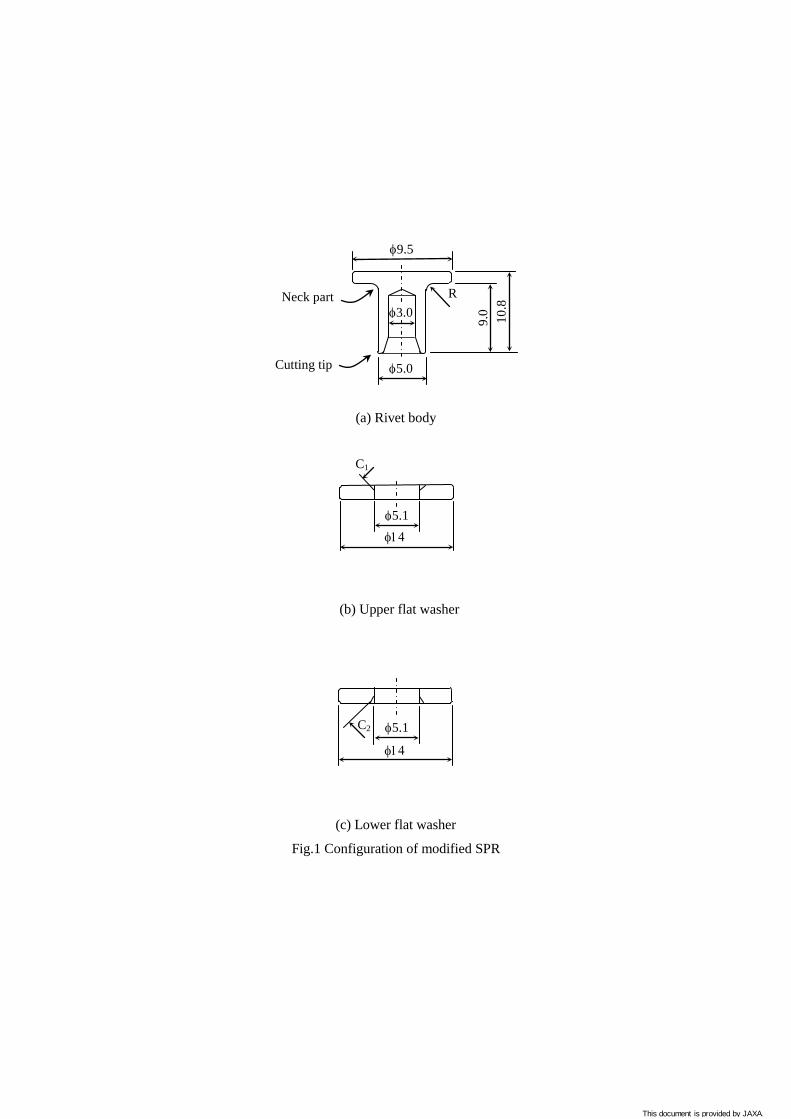
(a) Rivet body
(b) Upper flat washer
(c) Lower flat washer
Fig.1 Configuration of modified SPR
C2
φ14
φ5.1
φ14
C1
φ5.1
φ9.5
φ5.0
9.0 10.8
φ3.0 R
Cutting tip
Neck part
This document is provided by JAXA.

(a) Before joining (b) After joining
Fig.2 Joining of CFRP laminates by modified SPR
(4) Lower supporting die
(1) Upper flat washer
Upper CFRP laminate
Pressure
Pressure
(3) Upper supporting die
(2) Lower flat washer
Lower CFRP laminate
This document is provided by JAXA.

(a) Piercing process
(b) Swaging process
Fig. 3 Load-time curves in the fastening process
Load
[kN
]
40
30
20
10
0
Time [sec] 0 0.1 0.2 0.3 0.4
50
Swaging of cutting tip
Load
[kN
]
20
15
10
5
0
Time [sec] 0 0.5 1.0 1.5
Piercing of CFRP
6.5kN
This document is provided by JAXA.
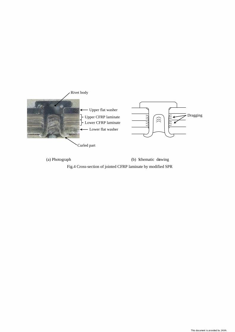
(a) Photograph (b) Schematic drawing
Fig.4 Cross-section of jointed CFRP laminate by modified SPR
Upper flat washer
Lower flat washer
Upper CFRP laminate
Rivet body
Curled part
Lower CFRP laminate
Dragging
This document is provided by JAXA.
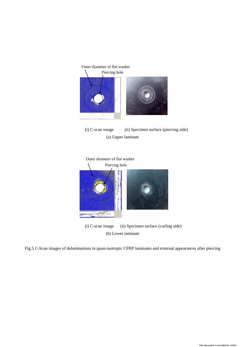
(i) C-scan image (ii) Specimen surface (piercing side)
(a) Upper laminate
(i) C-scan image (ii) Specimen surface (curling side)
(b) Lower laminate
Fig.5 C-Scan images of delaminations in quasi-isotropic CFRP laminates and external appearances after piercing
Piercing hole Outer diameter of flat washer
Piercing hole Outer diameter of flat washer
This document is provided by JAXA.

(a) Configuration of single lap joint
(b) Front view
(c) Side view
Fig.6 CFRP laminates jointed by modified SPR
Rivet body Upper flat washer
Lower flat washer
Rivet body
Upper flat washer
135 75 36
36
3.2 Piercing
Lower CFRP laminate (Curled side)
Upper CFRP laminate (Pierced side)
This document is provided by JAXA.
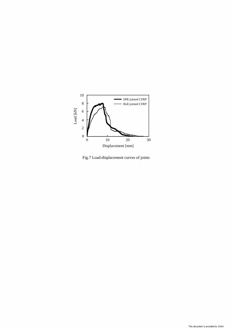
Fig.7 Load-displacement curves of joints
Bolt jointed CFRP
10
Load
[kN
]
8
6
4
2
0
Displacement [mm] 0 10 20 30
SPR jointed CFRP
This document is provided by JAXA.
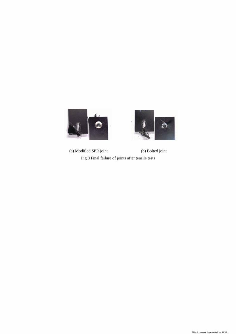
(a) Modified SPR joint (b) Bolted joint
Fig.8 Final failure of joints after tensile tests
This document is provided by JAXA.
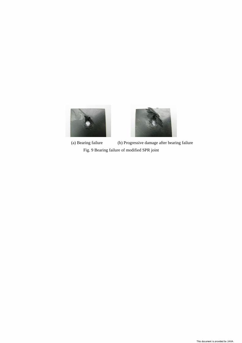
(a) Bearing failure (b) Progressive damage after bearing failure
Fig. 9 Bearing failure of modified SPR joint
This document is provided by JAXA.

Fig.10 Maximum load-cycles to failure curve of CFRP laminates jointed by modified SPR
0 102 10 103 104 105 106 107
Number of cycles to failure Nf
0
2
4
6
10
Max
imum
load
Pm
ax [k
N]
108
: Failure of CFRP : Failure of rivet
8
This document is provided by JAXA.
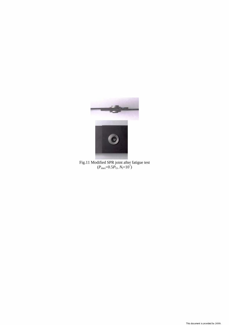
Fig.11 Modified SPR joint after fatigue test
(Pmax=0.5PU, Nf=107)
This document is provided by JAXA.

(a) Upper CFRP laminate (b) Lower CFRP laminate
Fig.12 C-scan images of CFRP laminates after fatigue test
(Pmax=0.5PU, Nf=107)
Piercing hole Outer diameter of flat washer
This document is provided by JAXA.

(a) Upper CFRP laminate (b) Lower CFRP laminate
Fig.13 C-scan images of CFRP laminates after fatigue test
(Pmax=0.4PU, Nf=107)
Piercing hole Outer diameter of flat washer
This document is provided by JAXA.