Embed Size (px)
Citation preview

INSTITUTE FOR FUSION STUDIES
DE-FG03-96ER-54346-750 IFSR #750
High-Mode-Number Ballooning Modes in a Heliotron/Torsat ron System: 11. St ability
N. NAKAJIMA~) Institute for Fusion Studies
The University of Texas at Austin Austin, Texas 78712 USA
a) Permanent address: National Institute for Fusion Science, Nagoya 464-01, Japan
May 1996
THE UNIVERSITY OF TEXAS
AUSTIN
MAST DJSJTUBUrrON OF THIS DOCUMENT IS UNLIMVIKEB


DISCLAIMER
This report was prepared as an account of work sponsored by an agency of the United States Government. Neither the United States Government nor any agency thereof, nor any of their employees, makes any warranty, express or implied, or assumes any legal liability or responsibility for the accuracy, completeness, or use- fulness of any information, apparatus, product, or process disclosed, or represents that its use would not infringe privately owned rights. Reference herein to any spe- cific commercial product, process, or service by trade name, trademark, manufac- turer, or otherwise does not necessarily constitute or imply its endorsement, mom- mendation, or favoring by the United States Government or any agency thereof. The views and opinions of authors expressed herein do not necessarily state or reflect those of the United States Government or any agency thereof.


High-mode-number ballooning modes in a heliotron/torsatron system: 11. Stability
N. Nakajima') Institute for Fusion Studies, The University of Texas at Austin
Austin, Texas 78712 USA
Abstract
As described in the companion paper [N. .Nakajima, Phys. Plasmas (1996)], in he-
liotron/torsatron systems that have a large Shafranov shift, the local magnetic shear is
found to have no stabilizing effect on high-mode-number ballooning modes at the outer side
of the torus, even in the region where the global shear is stellarator-like in nature. The disap-
pearance of this stabilization, in combination with the compression of the flux surfaces at the
outer side of the torus, leads at relatively low values of the plasma pressure to significant mod-
ifications of the stabilizing effect due to magnetic field-line bending on high-mode-number
ballooning modes-specifically, that the field-line bending stabilization can be remarkably
suppressed or enhanced. In an equilibrium that is slightly Mercier-unstable or completely
Mercier-stable due to peaked pressure profiles, such as those used in standard stability cal-
culations or observed in experiments on the Compact Helical System [S. Okamura,et al.
Nucl. Fusion 35, 283 (1995)], high-mode-number ballooning modes are destabilized due to
these modified stability effects, with their eigenfunctions highly localized along the field line.
Highly localized mode structures such as these cause the ballooning mode eigenvalues w2 to
have a strong field line dependence (i.e., a-variation) through the strong dependence of the
local magnetic curvature, such that the level surfaces of w2($, Bk, a) (5 0) become spheroids
a)Permanent address: National Institute for Fusion Science, Nagoya 46401, Japan
1

in ($, Oh, a) space, where $ labels flux surfaces and 81, is the radial wavenumber. Because
the spheroidal level surfaces for unstable eigenvalues are surrounded by level surfaces for sta-
ble eigenvalues of high-mode-number toroidal AlfvBn eigenmodes, those high-mode-number
ballooning modes never lead to low-mode-number modes. In configuration space, these high-
mode-number modes are localized in a single toroidal pitch of the helical coils, and hence
they may experience substantial stabilization due to finite Larmor radius effects.
PACS: 52.35.P~~ 52.55.H~
2

I. INTRODUCTION
The companion paper' examined the characteristics of the local magnetic shear in relation
to the properties of equilibrium quantities in an L = 2/M = 10 heliotron/torsatron system
like the Large Helical Device (LHD)2. Here, L and M are the polarity and toroidal pitch
number of the helical coils, respectively. In Ref. 1 it was shown that the stabilizing effects
due to the local magnetic shear can disappear on the outer side of the torus, even in the
region of stellarator-like strong global magnetic shear with s = 2- > 0, where c. is the
global rotational transform and $ is the flux surface label, with the latter being related to
the toroidal flux @T inside the flux surface $ through @T = 2n$. Also, it is pointed out in
Ref. 1 that the vanishing of the local magnetic shear is a universal feature, at least in L = 2
heliotron/torsatron systems with a large Shafranov shift.
d lnz
In the present paper, we combine these properties of the stabilizing effects due to the local
magnetic shear with those of the destabilizing effects caused by the local magnetic curvature
and analyze the stability of high-mode-number ballooning modes in an L = 2/M = 10
heliotron/torsatron system. We also clarify the relation of these modes to low-mode-number
modes.
The spectrum of ballooning modes in general toroidal systems has been investigated in
Ref, 3. In that work, a model tokamak with toroidal field ripple was used as an example
in order to study the affects of symmetry breaking on the ballooning spectrum. The level
surfaces for the eigenvalues were categorized in ($, Ole, a!) space, where a! labels the magnetic
field lines on the flux surface $, and Ole is the radial wavenumber. The eigenvalues whose
level surfaces are topologically cylindrical were intensively examined, because those surfaces
are the ones that continuously connect to the level surfaces for an axisymmetric tokamak
when the toroidal ripple is reduced.
3
.I

Recently, an examination similar to that in Ref. 3 was carried out for high-mode-number
ballooning modes in an LHD equilibrium with a broad pressure profile, thus strongly Mercier-
~ns t ab le .~ In that work, to compare the results from the high-mode-number ballooning
analysis with those hom the low-mode-number ballooning analysis, the high-mode-number
ballooning equation was modified so as to give the same kinetic energy norm as in the
low-mode-number equation. With this modification, the results from both analyses were
consistent; however, it was not clear how the kinetic energy norm affected the level surfaces
for the eigenvalues so obtained. Modifying the kinetic energy norm might induce a topological
change in the level surfaces for the eigenvalues, e.g., from cylindrical-type level surfaces to
spheroidal-type level surfaces or vice versa in ($, Bk, a) space.
In this paper, we will investigate the stability properties of high-mode-number balloon-
ing modes, both in strongly Mercier-unstable equilibria and in slightly Mercier-unstable or
completely Mercier-stable equilibria, for an L = 2/M = 10 heliotron/torsatron system with
a large Shafranov shift, with the use of the exact incompressible three-dimensional high-
mode-number ballooning mode eq~a t ion .~ The same vacuum magnetic configuration as in
Ref. 1 is used. The strongly Mercier-unstable equilibria correspond to broad pressure pro-
files, and the slightly Mercier-unstable or completely Mercier-stable equilibria6 correspond
to peaked pressure profiles. Depending on whether the Mercier criterion can be easily vio-
lated, the stability properties of the high-mode-number ballooning modes change, and this
change is reflected in the topological structure of the level surfaces for the eigenvalues. This
feature is important when the relationship between high- and low-mode-number modes and
also what toroidal mode numbers should be expected is considered. In Sec. 11, the global
characteristics of the equilibria with either broad or peaked pressure profiles are indicated.
The local characteristics of these equilibria are described in Sec. 111. In Sec. IV the stability
properties of high-mode-number ballooning modes are examined in terms of the global and
local equilibrium characteristics. The relationship between high- and low-mode-number bal-
4

looning modes and the influence of kinetic effects, such as finite Larmor radius (FLR), on
the high-mode-number modes are also addressed. Section V contains discussion.
11. GLOBAL EQUILIBRIUM CHARACTERISTICS
For the vacuum configuration, we will use the planar-axis L = 2/M = 10 heliotron/torsatron
configuration of Ref. 1. Currentless equilibria with finite$, where p is the ratio of the plasma
kinetic pressure to the magnetic field pressure, will be calculated with the use of the VMEC
code7 for fixed boundary conditions, with the boundary determined as the outermost flux
surface of the vacuum field. Two types of pressure profiles will be used in order to exam-
ine the relationship of Mercier stability to that of high-mode-number ballooning modes: a
peaked profile, given by
P($N) = Pop- $N)", (1)
and a broad profile, given by
P($N) = Po(1- $3". Here $N = is the normalized toroidal flux, with r N = 6 the normalized minor
radius. Note that the peaked pressure profile given in Eq. (1) is the profile that is normally
used in stability calculations for the LHD,' and that peaked pressure profiles similar to that
given in Eq. (1) are observed in ordinary experiments in Compact Helical System (CHS).8
'kedge
dc Figure 1 shows the global rotational transform c, the global magnetic shear s 3 Fa, the
index of the averaged magnetic well quantity VI' that measures the average magnetic well
(here a prime indicates the derivative: I f &), and the Mercier criterion parameter DM as
functions of the normalized toroidal flux. The upper set of graphs exhibit these quantities
for the peaked pressure profile of Eq. (l), and the lower set for the broad pressure profile
of Eq. (2). The three curves in each graph correspond to different central p values: Po = 0
(dotted curve), 4% (dot-dashed curve), and 8% (solid curve). For the vacuum configuration
5

considered here, the Shafranov shift is quite large, i.e., there is a substantial Pfmch-Schliiter
current. Consequently, the global rotational transform t and the global magnetic shear s
become highly deformed as p increases for both types of pressure profiles. In particular,
the global rotational transform t increases near the magnetic axis, but decreases near the
periphery. Because a region of tokamak-like global magnetic shear appears near the magnetic
axis and the stellarator-like magnetic shear is increased near the periphery, a shearless region
occurs between them, as can be seen in the graphs in Fig. 1 for the global magnetic shear.
As /3 increases, the global magnetic shear becomes very strong in the stellarator-like region
near the plasma periphery. Note, from Fig. 1, that all the curves for the global rotational
transform t cross each other at the same flux surface, for both peaked and broad pressure
profiles; this feature was analytically explained in Eq. (79) of Ref. 1. The occurrence of
the tokamak-like region of global magnetic shear near the magnetic axis is more evident for
the peaked pressure profile than for the broad pressure profile because the corresponding
Shafranov shift is larger, as will be later shown in Figs. 2 and 3. For the same reason, the
average magnetic well for the peaked pressure profile (V” < 0) is deeper than that for the
broad pressure profile, as shown in Fig. 1.
The behavior of the Mercier criterion parameter DM as shown in Fig. 1 can be understood
if we rewrite its expression in the following way:
with (f) G
Pfirsch-Schluter current divided by P’ is given by
J f dr . Also, 2nI is the net toroidal current inside the flux surface, and the
6

The expression in Eq. (3) was obtained, with some manipulations, from Ref. 9. Mercier
stability corresponds to satisfying the condition DM > 0. The first term on the right-hand
side of Eq. (3) represents shear stabilization. The last term is destabilizing, due to the
Pfirsch-Schliiter current (geodesic curvature) and the diamagnetic current. Only the second
term can change sign, depending on the average magnetic well quantity V” and the global
magnetic shear c‘ for a currentless ( I = 0) equilibria. Note that in the L = 2/M = 10
heliotron/torsatron system being considered here, the inequality ( (:z:r)O holds. With
the use of the relationship V’ = 2a( Ji-z I) (B2) , we can write Eq. (3) as follows:
Thus, it is clear that having an average magnetic well, i.e., (B2)’(>
global magnetic shear, i.e., c’(> 0), are critical for Mercier stability.
0), and having positive
For an L = 2/M = 10 heliotron/torsatron system with a large Shafrmov shift, the
dominant contribution to Mercier stabilization near the magnetic axis, where the global
magnetic shear is weak, comes from the magnetic well term, i.e., (V” < 0 or (B2)’ > 0),
whereas the dominant contribution to Mercier stabilization near the plasma periphery is the
global magnetic shear term, 7, since a magnetic hill, i.e., V“ > 0 or (B2)‘ < 0, occurs
here. For the peaked pressure profile with its monotonically increasing gradient, these two
stabilizing contributions work well together, so that an equilibrium with Po = 4% that
is slightly Mercier-unstable becomes completely stabilized when Po exceeds approximately
7%. This behavior implies the existence of second stability for the Mercier criterion, as
shown in Fig. 1 in the upper graph for DM. In contrast, the broad pressure profile has its
steepest gradient in the magnetic hill region where V“ > 0 or (B2)’ < 0. Since this strongly
destabilizing effect cannot be overcome by the magnetic shear term, the equilibrium with
@‘I2
7

the broad pressure profile is quite Mercier unstable, as indicated in the lower graph for DM
in Fig. 1.
111. LOCAL EQUILIBRIUM CHARACTERISTICS
A. Local magnetic shear
For the sake of completeness, the local magnetic shear examined in Ref. 1 is briefly
discussed. The Boozer coordinate system8 uses the radial, poloidal, and toroidal coordinates
($, 8, C) . Equally spaced ($, 8) meshes in the Boozer coordinate system, for both the peaked
and broad pressure profiles, are shown in Fig. 2 on a horizontally elongated poloidal cross
section and in Fig. 3 on the vertically elongated poloidal cross section. The upper graphs in
Figs. 2 and 3 are for the peaked pressure profile, and the lower graphs for the broad pressure
profile. In both Figs. 2 and 3, the three upper graphs correspond, respectively, to the central
beta values of ,& = 0,4, and 8% (from left to right), and likewise for the lower graphs. The
peaked pressure profile leads to a larger Shafranov shift than does the broad pressure profile,
as can be seen in Figs. 2 and 3.
Another useful covering space is the field line coordinate system ($, q, a), which is related
to the Boozer coordinate system ($, 8, C ) as
(6) 1 a=C--e , t
7 = 4
In Ref. 1 it was described how the local magnetic shear
global magnetic shear s and its oscillatory component Z, as follows:
can be expressed in terms of the
Here the various metric components are defined as
8

Also, 27rJ and 2nI is the poloidal net current outside of the flux surface, 2nI is the toroidal
net current inside the flux surface, and Q is the label for the magnetic field lines. Note that
I = 0 for a currentless equilibria. From Eq. (7), the integrated local magnetic shear along a
magnetic field line is given by
with 8k the radial wavenumber. The domain of the covering space is $,min < $ < and -03 < r],a < 03. In the coordinate system used here, 0 = 0 or r] = 0 corresponds to
the outer side of the torus. The oscillatory component 5 is determined by how much local
compression of the poloidal field on the outer side of the torus is needed to maintain toroidal
force balance. In the Boozer coordinate system, the magnetic field lines are represented as
straight lines, and the toroidal angle C is very similar to the geometrical toroidal angle in
a planar axis heliotron/torsatron system.' Therefore, almost all the information about the
local compression of the poloidal field appears in the behavior of the poloidal angle 8, as
can be seen in Figs. 2 and 3. Thus, 5 has a component proportional to g+e in Eqs. (7) and
(9). Near the magnetic axis, the global magnetic shear s is tokamal-like (s < 0) for the
peaked pressure profile or very small (s N 0) for the broad pressure profile; this property
can be seen in the upper and lower graphs for s in Fig. 1. Therefore, the local compression
of the poloidal field increases radially outward in order to maintain toroidal force balance:
g+e - csinB with c > 0, which leads to the situation with s 5 0 and > 0. In contrast,
near the plasma periphery, the global rotational transform exceeds unity and the global
magnetic shear s is strongly stellarator-like (s > 0). The local compression of the poloidal
field decreases radially outward, due to the large poloidal field on average: g+e - c sin 8 with
c < 0, which leads to the situation with s > 0 and Z < 0. Figures 2 and 3 show that for
both types of cross sections and both types of pressure profiles, as the value of increases,
there appears a turning surface (i.e., where g+e = 0), whose location depends on the global
.I
9

rotational transform .t and the pressure profile.'
The reduction of the stabilizing effect of the local magnetic shear is exhibited in Fig. 4(a),
where the integrated local shear, [/" Zdr]] , for Ok = 0, is plotted along a field line for the
peaked pressure profile equilibrium, with PO = 8%. For this graph, the field line with
$JN = 0.56 and a = 0 was chosen; on a horizontally elongated cross section, this field line
passes through the outer midplane of the torus. Note that the position at which r] = 0
corresponds to the outer midplane of the torus. For reference, the average integrated local
shear ( ~ r ] ) ~ is also plotted in Fig. 4(a). The same two quantities are shown in Fig. 5(a), but
for the equilibrium with the broad pressure profile, with PO = 4%; here, the magnetic field
line with $N = 0.39 and a = 0 was chosen. This field line also passes through the outer
midplane of the torus on a horizontally elongated cross section. Both the $N = 0.56 and the
$JN = 0.39 flux surfaces are located in the region where the global shear is stellarator-like in
nature. By comparing Figs. 4(a) and 5(a), we find that as P increases, the stabilizing effect
of the local magnetic shear near p = 0 is significantly reduced.
2
The monotonically increasing profile of the global rotational transform c near the periph-
ery of a finite-P plasma basically comes about from the vacuum configuration, as can be seen
in Fig. 1. Hence, the vanishing of the (integrated) local magnetic shear at the outer side of
the torus does not strongly depend on either the type of pressure profile or the magnetic field
line label a as the value of p increases. It follows that the stabilizing effect of the integrated
local magnetic shear on high-mode-number ballooning modes is not much influenced by the
pressure profile or the magnetic field line label a, except that the critical ,f3 value at which
the local magnetic shear vanishes does depend on the pressure profile. The reduction (or
disappearance) of the stabilizing effect of the local magnetic shear in the region where the
global shear is stellarator-like is a universal feature, at least in L = 2 heliotron/torsatron
systems with a large Shafranov shift, since it is caused by the Shafranov shift (i.e., toroidal
force balance) for the stellarator-like global magnetic shear inherent in such systems.
10

B. Local shape of flux surfaces
At the outer side of the torus, the flux surfaces are locally compressed, because this is
where the compression of the poloidal field varies radially. This situation is reflected in the
local shape of the flux surfaces at the outer side of the torus, as expressed by IO$[. As
shown in the poloidal cross sections with Po = 8% in Figs. 2 and 3, the variation of [V$l
in the minor radius direction significantly changes across the turning surface on the outer
side of the torus. At the outer side of the torus, adjacent flux surfaces become progressively
nearer to each other in radius as the turning surface is approached. In other words, the flux
surfaces become more and more compressed. Once the turning surface is crossed, however,
the flux surfaces become less compressed radially. The local compression of the flux surfaces
at the outer side of the torus causes the flux surfaces to be locally uncompressed at the inner
side of the torus due to toroidal flux conservation. Thus, the change of the local shape of a
flux surface [V$[ along a field line is quite noticeable; this is shown in Figs. 4(b) and 5(b)
where the variation of the quantity 'v412 is plotted along the same field lines as in the top
graphs. The dashed line in each of these graphs, shown for reference, is the approximate value of - lV*I2 = 1 for a low+ tokamak with concentric circular flux surfaces. As @ increases,
27JBo
[ 091 is enhanced on the outer side of the torus, but reduced on the inner side. The variation
of [V$l along a field line becomes most significant in the vicinity of the turning surface,
where the interval between successive flux surfaces is smallest. Since it is caused by toroidal
force balance (i.e., the Shafranov shift), the local compression or decompression of the flux
surfaces becomes most noticeable as the value of @ increases; however, it is independent of
a, the magnetic field line label. Both of these features can be observed in Figs. 2 and 3 if
one examines the variation with and with the poloidal cross section.
The variation of the local shape of the flux surfaces [V$[ plays an important role in
the stabilization of high-mode-number ballooning modes for equilibria with large Shafranov
11

shifts. The reason for this can be seen from the expression for the perpendicular wavenumber
IkJ- I 1
where the secular stabilizing term, which is the dominant term in lkJ-12, has the following
form:
The secular stabilizing term s(7 - ek)10$1 is amplified through lV$l each time the field
line transits the outer side of the torus, near q = f2pn with p an integer, leading to an
enhancement of its stabilizing effect. On the other hand, each time the field line transits the
inner side of the torus, near 7 = f(2p+l)n, the secular stabilizing term is diminished through
lV$l, leading to the reduction of its stabilizing effect. The characteristics of the local shape
of the flux surfaces as expressed by IO$/ are universal, at least for L = 2 heliotron/torsatron
systems.
In Figs. 4(c) and 5(c), the square of the wavenumber lkl12 is plotted along the same
field line as that for Figs. 4(a) and 5(a), respectively. These graphs show that the field line
bending stabilization effect on high-mode-number ballooning modes is strongly modified as p is increased in an L = 2 heliotron/torsatron system with a large Shafranov shift. Within one
poloidal period along the field line (171 < n), this stabilizing effect is significantly suppressed,
both because the local shear associated with the poloidal field which is compressed at the
outer side of the torus vanishes (Fig. 4(a)) and because the flux surfaces on the inner side
of the torus are decompressed (Fig. 4(b)). On the other hand, this stabilizing effect is
significantly enhanced farther out along the field line (171 - 27r) due to the local compression
of the flux surfaces at the outer side of the torus (Fig. 4(b)). This sort of modification is
universal in L = 2 heliotron/torsatron systems with a large Shafranov shift and is almost
independent of both the magnetic field line label and the pressure profile, except for the p
12

value at which the modification becomes significant.
C. Local magnetic curvature
The local magnetic curvature in heliotron/torsatron systems consists of two components.
One component is due to toroidicity, just as in a tokamak plasma. This mainly comes
from the vacuum toroidal field and hence has no dependence on a. The other component
is due to helicity (i.e., of the helical coils), which mainly arises from the saddle-like profile
for the magnetic field strength, reflecting that in a straight helix. On every poloidal cross
section, the outside of the torus corresponds to locally “bad” magnetic curvature, and the
inside to “good” curvature, in terms of the toroidicity contribution. In terms of the helicity
contribution, however, the regions between the helical coils correspond to the locally bad
magnetic curvature in each poloidal cross section, and the regions under the helical coils to
locally good curvature. The variation of the magnetic field strength due to the helicity is
comparable with that due to the toroidicity. Therefore, the local magnetic curvature is worst
at the outer side of the torus in a horizontally elongated poloidal cross section (cf. Fig. 2).
At the outer side of the torus in a vertically elongated poloidal cross section (cf. Fig. 3),
the locally bad magnetic curvature due to the toroidicity is canceled by the locally good
magnetic curvature due to the helicity. Thus, the local magnetic curvature at the outer side
of the torus strongly depends on a, the label of the magnetic field line in the covering space
($, 7, a). This situation is completely different from that in a tokamak plasma. In a tokamak
plasma, the local magnetic curvature is independent of the field line label CY because of the
to r oidal symmetry.
The dependence of the local magnetic curvature on the pressure profile is not clear,
because the effect of the pressure profile on the local magnetic curvature mainly enters
through the shape of the flux surface, as can be seen from the expression for the magnetic
13

curvature:
where VI is the gradient perpendicular to the magnetic field and 2 is the unit vector along
the field. From Eq. (12), another expression for the magnetic curvature can be obtained,
in which the magnetic curvature is decomposed in terms of the normal magnetic curvature
K n , given by K~ = -- 24 8 (P + :) - - 24P (E + *$) B,
B2 84 B 3 4 8C and the geodesic magnetic curvature K ~ , which is given by
Here brackets indicate a flux surface average, and p is obtained by solving the following
magnetic differential equation:
The contravariant form of the normal magnetic curvature, rcn, is expressed as
In Figs. 4(d) and 5(d), the contravariant normal magnetic curvature is shown plotted
along the magnetic field line. The phase due to the toroidicity and that due to the helicity
are both quite evident. At the outer side of the torus, where 7 = 2pn with p an integer, locally
unfavorable magnetic curvature occurs near 7 = 0 and f 4 n , but locally favorable curvature
at 7 = f2n. Because of such behavior, the local magnetic curvature is expected to have a
strong dependence on the magnetic field line (i.e., on a). This sort of strong magnetic field
line dependence (0-dependence) by the local magnetic curvature is a universal feature in
helio tron/ t orsatron systems with appreciable helical ripple.
14
IV. STABILITY PROPERTIES
Before examining the stability properties of high-mode-number ballooning modes and the
relation between high-mode-number and low-mode-number modes, we will present a brief
summary of the global and local equilibrium characteristics. In addition, the last three points
in this list summarize some other useful information.
1. The reduction or vanishing of the stabilization effect of the local magnetic shear F in
the region of stellarator-like global magnetic shear is a universal feature, at least in
L = 2 heliotron/torsatron systems with a large Shafranov shift. The dependence of F
on the field line label a! and on the type of pressure profile is weak, since the behavior of
S is determined by toroidal force balance with a stellarator-like global magnetic shear,
such as is inherent in L = 2 heliotron/torsatron systems.
2. As the value of p increases, the local shape of the flux surfaces as expressed by
enhances the stabilizing effect from the secular term in lkll at the outer side of the
torus, but reduces it at the inner side. The effect of local compression or decompression
of flux surfaces on this stabilizing term, coming through toroidal force balance, is almost
independent of a! and the type of pressure profile. This, too, is a universal feature in
L = 2 heliotron/torsatron systems with a large Shafranov shift.
3. As p increases, the stabilization from field line bending is significantly reduced within
one poloidal period along the field line ( [ V I < T ) , but significantly enhanced farther
out along the field line. This feature is due to the superposition of the preceding
two characteristics in this summary list. This feature is universal, at least in L = 2
heliotron/torsatron systems with a large Shafranov shift.
4. A universal feature in heliotron/torsatron systems with appreciable helical ripple is
that the local magnetic curvature at the outer side of the torus depends on a!.
15

5. The pressure profile has a significant affect on the Mercier criterion because there is
always an average magnetic hill near the plasma periphery. A peaked pressure profile
leads to a slightly Mercier-unstable or a completely Mercier-stable equilibrium, whereas
a broad pressure profile leads to a strongly Mercier-unstable equilibrium.
6. In the high-mode-number ballooning equation, typically there are three spatial scale
lengths along the magnetic field line. For strong global shear, these scale lengths have
the following ordering,
whereas for weak global shear, these scale lengths are ordered as follows,
c Here, 1 and a are the scale lengths determined by the toroidicity and the helicity,
respectively, while the scale length $ arises from the secular term in the local magnetic
shear integrated along the magnetic field line, given by Eq. (9).
7. In the integrated local magnetic shear , which appears in the perpendicular wavenum-
ber, given in Eq. (lo), the scale length due to the toroidicity determines the typical
scale of its envelope around the secular term having the scale length of $, while its
rapid modulation is due to the helicity.
8. The normal and geodesic components of the magnetic curvatures have variations both
on the toroidicity scale length and also on the helicity scale length.
9. The parameter DM that describes the Mercier criterion is derived from an asymptotic
analysis of the exact high-mode-number ballooning mode equation with zero frequency.
For equilibria that are Mercier stable, the high-mode-number ballooning equation has
solutions that decay along the magnetic field line in the asymptotic region, i.e., where
16
7 - 81, >> 0. On the other hand, Mercier-unstable equilibria correspond to solutions of
the high-mode-number ballooning equation that have oscillatory asymptotic behavior
along the field line.
10. Ballooning modes with large growth rates tend to be localized along the field line.
(This feature can be easily understood from the variational form for the high-mode-
number ballooning equation.) On the other hand, modes near marginal stability tend
to be extended along the field line.
11. A crucial difference between a heliotron/torsatron system and a tokamak is the de-
pendence of equilibrium quantities on the field line label a in covering space ($, q, a)
for the former. In a helical system, the eigenfunctions for high-mode-number balloon-
ing modes depend on the poloidal angle q in the three-dimensional parameter space
($, &, a), and hence the corresponding eigenvalues depend on the three parameters
($,&,a). By contrast, the eigenfunctions in a tokamak depend on q in the two-
dimensional parameter space ($, &), and thus the corresponding eigenvalues depend
on only two parameters ($, 0,).
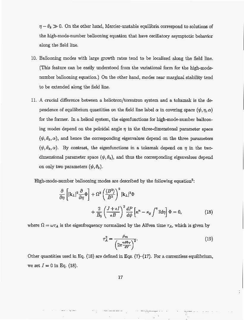
High-mode-number ballooning modes are described by the following equation5:
+ - 2 ( B ) 2 J + L I dP [kn - ~ ~ / ' S d q ] @ = 0, BO
where 52 = WTA is the eigenfrequency normalized by the Alfven time TA, which is given by
Pm T i = 2 '
(22%)
Other quantities used in Eq. (18) are defined in Eqs. (7)-(17). For a currentless equilibrium,
we set I = 0 in Eq. (18).
17
: I

We will numerically solve Eq. (18) in the covering space ($J, 7, a), which is related to
the Boozer coordinate system ( $ J , O , < ) by Eq. (6). The boundary condition used for the
numerical solution of Eq. (18) is @ = 0 at 17 - O,l = p x 2n, where the choice of the appro-
priate value for the integer p depends on the convergence properties of the eigenfunctions
for various parameters. For modes localized along a field line, we typically used p = 4. For
modes with extended structure along a field line, we typically used p = 32. After having
obtained a solution with eigenvalue 52;) we slightly reduced the position of the boundary,
say, by bp = j x 0.05 with j = 1,2, - e , and again obtained the solution, with corresponding
eigenvalue G?;. Then, if the difference SG?; = + is smaller than we treated G?: as
the true eigenvalue. To solve Eq. (18), we usually used the sixth-order Runge-Kutta numer-
ical method. Occasionally the Adams method was used to check the solutions obtained by
means of the sixth-order Runge-Kutta method.
IQ;-Sl?j QO
To calculate the equilibria, the VMEC code7 was used, with fixed boundary conditions,
for 121 radial grids and 7 poloidal harmonics (with mode numbers m = 0 N 6) and 13
toroidal harmonics (with mode numbers n = -6 N 6). The transformation from the VMEC
magnetic coordinate system to the Boozer magnetic coordinate system was carefully carried
out with the use of Eqs. (22) and (25) of Ref. 1. In order to carry out this transformation
with precision, 120 poloidal harmonics (with mode numbers m = 0 - 119) and 25 toroidal
harmonics (with mode numbers n = -12 - 12) were used in the Boozer coordinate system.
As was described in Ref. 1, the poloidal angle of the VMEC coordinate system is an optimized
angle, which is similar to the poloidal angle proportional to the arc length (“uni-arc angle”),
whereas the toroidal angle of the VMEC coordinate system is simply the geometrical toroidal
angle. Because the poloidal angle of the Boozer coordinate system is greatly deformed from
the uni-arc poloidal angle near the shearless region (cf. Figs. 2 and 3), many harmonics are
needed. The toroidal angle of the Boozer coordinate system, however, is very similar to the
usual geometrical toroidal angle in a planar-axis heliotron/torsatron system, and hence a
18

small number of toroidal harmonics is sufficient. The maximum relative errors in B and R
due to the transformation at the grid points are approximately respectively.
The basic domain for the ($,&,a) space is $,in 5 $ 5 $ m a or (0 5 $N 5 l), -T 5
Ok 5 T , and 0 5 a 5 s. Note that a heliotron/torsatron equilibrium with M as the toroidal
pitch number of the helical coils have an M-fold periodicity in the toroidal direction, with
the basic domain for a correspondingly reduced. All of the numerical calculations described
in the present paper are performed in this basic domain.
and
A. Equilibria that are strongly Mercier-unstable
Figure 6 shows the variation with a and the $-dependence of the unstable eigenvalues R2,
with t9k = 0, for the broad pressure profile given by Eq. (2) with 80 = 4%. This equilibrium
has flux surfaces that are strongly Mercier-unstable, as seen in Fig. 1. A comparison of
Fig. 6 with the graphs for DM in Fig. 1 shows that the region unstable with respect to high-
mode-number ballooning modes radially overlaps the Mercier-unstable region. Also, when
we compare Fig. 6 with the graphs for s in Fig. 1, we find that these high-mode-number
modes are located in the region where the global magnetic shear is stellarator-like. In Fig. 6,
the open circles indicate eigenvalues R 2 ( $ ~ , & = 0, a = 0) where the chosen field line with
a = 0 passes through the place where the magnetic curvature is locally most unfavorable,
i.e., on the outer side of the torus at r] = 0 in a horizontally elongated poloidal cross section.
The open squares in Fig. 6 indicate eigenvalues R 2 ( $ ~ , & = 0,a = 5) where the selected
field line with a = 6 passes through the point where the magnetic curvature is locally most
favorable, i.e., on the outer side of the torus at r] = 0 in a vertically elongated poloidal cross
section.
For parameters such that the high-mode-number ballooning modes are marginally sta-
ble, the a-dependence of the eigenvalues R2 is so weak that high-mode-number ballooning
modes can become unstable even in the region where the magnetic curvature is locally most
19
favorable, i.e., a = %. In particular, the a-dependence is quite weak in the region $JN =
0.35 N 0.45 where the global shear is small. The eigenfunction @(+N = 0.39,& = 0, a = 0)
obtained from Eq. (18) in this region is shown in the top graph of Fig. 7. The modulation
due to the toroidicity is evident, but there is almost no perceptible affect due to the helicity.
Since the condition $ > 1 is satisfied in this region, i.e., the scale length for the secular
stabilizing term in lkll that arises from the global magnetic shear s is longer than that
due to the toroidicity, the eigenfunction @ has a considerably extended structure along the
magnetic field line, extending over regions where the magnetic curvature is both locally un-
favorable and favorable (in terms of the toroidicity). The structure of the eigenfunction has
several peaks on the outer side of the torus, reflecting the toroidicity scale length in the local
magnetic curvature. This type of extended structure with several peaks on the outer side
of the torus indicates that high-mode-number modes with a = $ experience destabilization
from adjacent regions of locally unfavorable magnetic curvature region at the outer side of
the torus-which in turn leads to the a-dependence of R2 being weak. High-mode-number
ballooning modes being nearly marginally stable in the region where the global magnetic
shear is weak have a correspondence to weakly ballooning modes in tokamaks.5
Near marginal stability, in the region ($JN = 0.7 N 0.8) where the global magnetic shear
is relatively strong, the toroidicity scale length is larger than that due to the global magnetic
shear in the secular term: i.e., 1 > 4. In this case, the eigenfunction has a localized
structure, with little oscillatory behavior, as shown in the bottom graph in Fig. 7. This type
of localized structure prevents the eigenmode from experiencing destabilization at adjacent
regions on the outer side of the torus where the magnetic curvature is locally unfavorable, and
hence the a-dependence of R2 becomes stronger than in the case when the global magnetic
shear is low. Eigenfunctions that are near marginal stability with 0 > R2 > min R 2 ( $ ~ , 81, =
0,a = $) have extended structures along the magnetic field line, and the a-dependence
of their eigenvalues is so weak that the domain of unstable eigenvalues is unbounded with
20

respect to a. Then, since the unstable eigenvalues are bounded in both $ and &, the level
surfaces for the eigenvalues are topologically cylindrical in ($, &, a) space.
Away from marginal stability, the a-dependence of the eigenvalues f12 becomes fairly
strong. This can be seen in Fig. 6 where cross points indicate the a-dependence of the
most unstable eigenvalue R 2 ( $ ~ = 0.66,Ok = 0,a) plotted for the several values a = & for j = 0,1, . - - , 5. The scale length for the global magnetic shear in the secular term is
smaller than that for the toroidicity: i.e., 1 > $. A typical eigenfunction G($JN = 0.66,& =
0,a = 0) is shown in the middle graph of Fig. 7. The rather localized non-oscillatory
structure of this eigenfunction results from the 1 > 3 ordering of the different scale lengths.
Localized high-mode-number ballooning modes- such as this, which are not near marginal
stability, have a correspondence to strongly ballooning modes in tokamaks, apart from the
strong dependence on a. Since high-mode-number ballooning modes with large growth
rates, i.e., R2 < minR2($N,& = 0,a = g), tend to be localized along field lines, their
strong a-dependence causes the domain of unstable eigenvalues to be bounded with respect
to a, and hence the level surfaces for the eigenvalues in ($,&,a) space are topologically
spheroidal. Otherwise, these strongly localized ballooning modes would be destabilized even
in the region where the magnetic curvature is locally favorable, if the eigenfrequency w2 has
week dependence on a.
Our numerical results show that the more highly localized the eigenfunctions are, the
stronger their a-dependence becomes, which causes the level surfaces for the eigenvalues to
be transformed topologically from being cylindrical to being spheroidal.
B. Equilibria that are slightly Mercier-unstable or completely Mercier-st able
For the peaked pressure profile of Eq. (1) with = 4%, the high-mode-number bal-
looning modes are found to be completely stable, even though this equilibrium is slightly
21
Mercier unstable, as shown in Fig. 1. When Po goes up to about 6%, the high-mode-number
ballooning modes become unstable, whereas the Mercier modes are only slightly unstable.
The equilibrium with PO = 8% is completely Mercier stable; i.e., it has a second stability
regime with respect to interchange modes. The high-mode-number ballooning modes, how-
ever, are more unstable with ,& = 8% than with ,& - 6%. The $-dependence of the stable
and unstable eigenvalues R2 with t9k = 0 and a = 0 is shown in Fig. 8 for the peaked pressure
profile with Po = 8%. The growth rates are quite large; i.e., these high-mode-number modes
are strongly ballooning modes apart from their significant a-dependence. A comparison of
Fig. 8 with the graphs for s of Fig. 1 shows that these modes become unstable in the region
where the global magnetic shear is stellarator-like.
The eigenfunction corresponding to the most unstable eigenvalue, viz., @($p, = 0.56, t9k =
0,ct = 0), is shown in the middle graph of Fig. 9. Since the scale length for the global
magnetic shear is smaller than that for the toroidicity and because the typical growth rates
are very large, the eigenfunction is highly localized along the magnetic field line. This
localized structure along the field line does not change for unstable eigenfunctions near
the marginal stability of high-mode-number ballooning modes. Moreover, even the stable
eigenfunctions in the vicinity of the marginal stability, shown in the top and the bottom
graphs of Fig. 9, have a highly localized structure, similar to that shown in the middle graph
of Fig. 9, i.e., regardless the sign and magnitude of the eigenvalues the eigenfunctions of the
discrete modes have a highly localized structure.
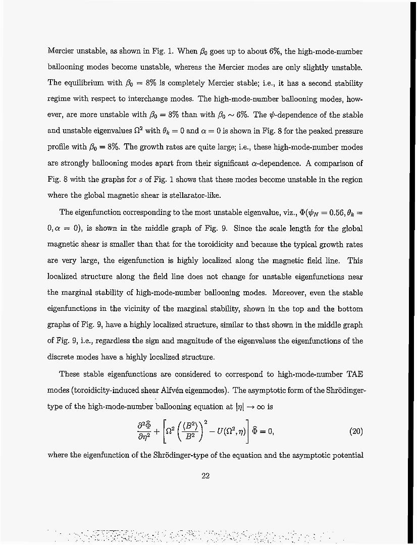
These stable eigenfunctions are considered to correspond to high-mode-number TAE
modes (toroidicity-induced shear Alfven eigenmodes) . The asymptotic form of the Shrodinger-
type of the high-mode-number ballooning equation at 171 3 00 is
where the eigenfunction of the Shrodinger-type of the equation and the asymptotic potential
22

are, respectively, given by
From the solution of Eq. (20) we can understand the boundaries between spectral gaps
and the Alfvkn continuum. The modulation of flux surfaces due to a large Shafranov shift,
expressed by IO$[, is noticeable as shown in Fig. 4(b). Since a large Shafranov shift enhances
the Fourier components with phases of toroidicity, ellipticity, and triangularity in lV$l, the
first, second, and third spectral gaps become quite large. Thus, the width of the Alfvkn
continuum between spectral gaps becomes quite narrow. The rather narrow width of the
first Alfv6n continuum between a2 = 0 and the lower boundary of the first gap leads to very
small eigenvalues for the descrete stable eigenmodes (TAE modes) near the lower boundary
of the first gap, as shown in Figs. 8 and 9. Also, the rather narrow width of the second
Alfvkn continuum between the first and the second spectral gaps leads to a large variation of
the eigenvalues of high-mode-number TAE modes, shown in Fig. 8. The overall structure of
the eigenfunctions for high-mode-number TAE modes is quite similar to that for high-mode-
number ballooning modes, except that the former becomes negative at 171 = 27r, which is
somewhat difficult to distinguish in Fig. 9. This structure reflects the typical periodicity of
high-mode-number TAE modes, namely, 47r. More detailed explanation of the high-mode-
number TAE modes and their relationship to high-mode-number ballooning modes will be
presented in a separate publication.
The top graph in Fig. 10 shows the &-and $-dependences of the eigenvalues C12 for QI = 0.
The calculation area is 0.422 5 $N 5 0.791 and -0.03 5 2 5 0.03 The area indicated by the
thick closed curves corresponds to the contours for the negative eigenvalues of high-mode-
number ballooning modes, and the area indicated by the thin unclosed curves to the contours
for the positive eigenvalues of high-mode-number TAE modes. Note that the unstable region
23

in 81, is very narrow. The lower graph of Fig. 10 shows the &-and a-dependences of the most
unstable eigenvalue a' on the flux surface +N = 0.56. The contours indicated by thick
curves, centered at = 0,1, and 2, correspond to the negative eigenvalues of high-mode-
number ballooning modes. In contrast, the contours indicated by thin curves, centered at
0- 2alM - 0.5 and 1.5, correspond to the positive eigenvalues of high-mode-number TAE modes.
Due to their highly localized structure along the field line, the high-mode-number ballooning
modes alternate between instability and stability as a is varied, and consequently the level
surfaces for the unstable eigenvalues have the topological form of spheroids in (+,&,a)
space.
In a slightly Mercier-unstable or completely Mercier-stable equilibrium, there are no
cylindrical level surfaces of a2( 5 0) that exist near marginal stability surrounding the spher-
ical level surfaces of a'(< 0) in a strongly Mercier-unstable equilibrium. The reason for this
is as follows: In a slightly Mercier-unstable or completely Mercier-stable equilibria with a
peaked pressure profile, the destabilization of high-mode-number ballooning modes is weak
compared with that for a strongly Mercier-unstable equilibria for which the maximum of the
pressure gradient is located in the Mercier-unstable region. Thus, high-mode-number bal-
looning modes in a slightly Mercier-unstable or completely Mercier-stable equilibrium with
a peaked pressure profile begins to become unstable after the stabilization is suppressed
through a large Shafranov shift due to significant compression or decompression of the flux
surfaces at the outer side or inner side, respectively, of the torus. Thus, the perpendicular
wavenumber lkll becomes quite small within the poloidal region lql 5 2n, partially due to
the reduction or vanishing of the stabilizing effect of the local magnetic shear near q = 0,
and partially due to the reduction of the secular stabilizing term in lkll near lql = 7~ on
account of IO$] being considerably reduced. In contrast, the secular stabilizing term in lkll
is much enhanced near lql = 2n by the increase in IO$]. Therefore, it follows that the eigen-
functions of the unstable high-mode-number ballooning modes are localized within lql = 2n
24

even for eigenvalues near marginal stability. This leads to such a strong a-dependence of
the eigenvalue R2 that the level surfaces for R2(L 0) become spheroids. In other words,
unstable eigenvalues do not have cylindrical level surfaces, and the spheroidal level surfaces
for unstable eigenvalues are immediately surrounded by stable eigenvalues R2 > 0 of high-
mode-number TAE modes. In contrast, high-mode-number ballooning modes in a strongly
Mercier-unstable equilibria with a broad pressure profile become unstable before the sta-
bilizing effects are suppressed. Thus, the eigenfunctions do not have a localized structure,
which leads to a weak a-dependence of the eigenvalue R2, and consequently the cylindrical
level surfaces for 0' (5 0) exist near the magninal stability.
The spectrum of the eigenvalues a 2 ( $ ~ , Bk, a) can be expressed as3
with & = a + qBk. The spectrum for the particular eigenvalue R 2 ( $ ~ = 0.56, Bk, a) is shown
in Fig. 11. One contribution to the spectrum comes from the toroidicity (the n = 0 com-
ponents). The other contribution comes from the helicity (the n # 0 components). Among
the n = 0 components due to the toroidicity, and are positive (i.e., stable),
while most of the negative (i.e., unstable) contribution comes from the broad spectrum of
higher harmonics with m 3 3. The dominant components due to the helicity (namely, the
components with n = 10) have a broad spectrum in m and contribute a significant nega-
tive (unstable) contribution, thus indicating a strong a-dependence of the eigenvalues. The
broad spectrum with respect to m indicates that the width in Bk of the level surfaces for w2
is very narrow.
C . Stability properties of high-mode-number modes and their relationship to low-mode-number modes
We can now categorize the high-mode-number ballooning modes in heliotron/torsatron
systems into two types and investigate their proper tie^.^ One type of high-mode-number
25 .I

ballooning mode has level surfaces for its unstable eigenvalues S-2' that are topologically
cylindrical in ($, &, a) space. This type of high-mode-number ballooning mode occurs only
near Mercier marginal stability in an equilibrium that is strongly Mercier-unstable due to
a broad pressure profile. The high-mode-number modes that have small growth rates are
significantly extended along a magnetic field line, extending over several poloidal periods
with locally unfavorable and favorable magnetic curvature regions at the outer side of the
torus.
The other type of high-mode-number ballooning mode has level surfaces for the unstable
eigenvalues S-2' that are topologically spheroidal in ($> f3kj a) space. These high-mode-number
modes arise in two different ways. For a strongly Mercier-unstable equilibrium with a broad
pressure profile, this type of mode occurs in the strongly Mercier-unstable region, far from
marginal stability. It follows that the spheroidal level surfaces of the eigenvalues are sur-
rounded by the cylindrical level surfaces for the unstable eigenvalues in (+, &, a) space. For
a slightly Mercier-unstable or completely Mercier-stable equilibrium with a peaked pressure
profile, only this type of high-mode-number mode occurs, so that the spheroidal level sur-
faces for the unstable eigenvalues are surrounded in ($,&,a) space by the level surfaces
for the stable eigenvalues of high-mode-number TAE modes. The high-mode-number modes
with large growth rates are extremely localized along a magnetic field line.
In order to examine the global structure of the high-mode-number ballooning modes, the
eikonal S($, a) must be specified on a level surface for R2 in (+, &, a) space. Doing so leads
to information about the low-mode-number ballooning modes. For this purpose, the method
of characteristics will be used. Hence, the following ray equations will be solved3:
26

Hereafter, the safety factor q will be used instead of $.
derivative with respect to a dummy time variable that
Also, the function A represents the dispersion relation:
The eikonal S is constant along a ray trajectory.
In Eqs. (23)-(25), Lr denotes the
parameterizes the characteristics.
Since the unstable eigenvalues (w2 < 0) are bounded in &, the poloidal periodicity
requirement on the eikonal is ~atisfied.~ Thus, unstable eigenvalues with cylindrical level
surfaces in (4, &, a) space must satisfy both the requirement that the eikonal S have toroidal
periodicity and also the requirement that it be single-valued in q. These requirements lead to
a quantization condition, from which the toroidal mode number of the ballooning modes is
determined. For high-mode-number modes whose eigenvalues have cylindrical level surfaces,
a tokamak-like treatment can be applied to determine the global radial structure and the
typical toroidal mode number. Furthermore, high-mode-number modes of this sort will be
continuously connected to low-mode-number ballooning modes.4
On the other hand, high-mode-number ballooning modes whos eigenvalues have spheroidal
level surfaces are essentially three-dimensional in nature. Since both the poloidal and toroidal
periodicity requirements are satisfied, there remains only the requirement of single-valuedness
in q. Thus, the toroidal mode number is not a good quantum number, even in an approx-
imate sense. Moreover, being bounded in a implies that these high-mode-number modes
never connect to low-mode-number modes. At least one stable fixed point (a sink) and one
unstable fixed point (a source) exist on the spheroid, which are obtained from the solution
of Eqs. (23)-(25) with Lr = 4 = & = 0. The ray must spiral out of an unstable fixed point
and into a stable fixed point, whose eigenvalue corresponds to an unstable continuum band.3
27

The spheroids are highly elongated in Q! and highly contracted in &, as shown in Fig. 10.
From the following equation,
obtained from the combination of Eqs. (23) and (24), it can be expected that the change in
a! for a single rotation in both the 81, and the q directions is quite small.
These considerations concerning high-mode-number ballooning modes whose eigenvalues
have spheroidal level surfaces of eigenvalues in ($, &, CY) space indicate that finite-mode-
number ballooning modes should be expected to have the following stability properties:
Finite-mode-number modes will be excited in the region of locally unfavorable magnetic
curvature between adjacent helical coils at the outer side of the torus. The minimum toroidal
mode number to be expected is at least M, since a helical device with a toroidal pitch number
M has M periods in the toroidal direction. To be localized both toroidally and poloidally,
toroidal mode numbers M, 2M, 3M, 4M, are needed. Hence, finite Larmor radius
effects that can have a stabilizing effect on finite-mode-number ballooning modes become
significant, say, for M 2 10.
V. DISCUSSION
The stability properties of high-mode-number ballooning modes and their relationship to
low-mode-number modes has been examined in an L = 2/M = 10 heliotron/torsatron; here,
L and M are the polarity and the toroidal pitch number of the helical coils, respectively. The
exact incompressible high-mode-number ballooning mode equation was solved in the covering
space ($, q, a) for three-dimensional equilibria, where $ and a are the flux surface and the
magnetic field line labels, respectively, and q is the coordinate along the magnetic field line
(-co < 7 < ca). In heliotron/torsatron systems, the eigenvalues u2 are a function of +, &, and a, with 01, the radial wavenumber from the eikonal analysis, whereas in a tokamak
28

plasma the eigenvalues are not functions of a. Thus, the properties of high-mode-number
ballooning modes in heliotron/torsatron systems are mainly clarified by the magnetic field
line dependence of their eigenvalues w2.
In a heliotron/torsatron system with a large Shafranov shift, at relatively low-/? values
the large Shafranov shift reduces or cancels the stabilizing effect due to the local magnetic
shear at the outer side of the torus, even in the region where the global magnetic shear
is stellarator-like, and when strong compression of the flux surfaces due to the Shafranov
shift enhances the secular stabilizing part of the local shear at the outer side of the torus,
while strong flux surface decompression reduces it at the inner side. The superposition of
these effects leads to significant suppression of the stabilizing effects due to the perpendicular
wavenumber within the first poloidal period along the magnetic field line, and enhancement
at = 2n.
Broad pressure profiles lead to a highly Mercier-unstable equilibrium, with the maximum
pressure gradient located within the Mercier-unstable region. In contrast, peaked pressure
profiles lead to a slightly Mercier-unstable or completely Mercier-stable equilibrium, with
the maximum pressure gradient located within the Mercier stable region. Thus, it is easier
for high-mode-number ballooning modes to occur in equilibria with broad pressure profiles
than in equilibria with peaked pressure profiles. In other words, the /? value at which high-
mode-number modes occur in an equilibrium with a broad pressure profile is lower than that
in an equilibrium with a peaked pressure profile.
In highly Mercier-unstable equilibria with broad pressure profiles, the high-mode-number
ballooning modes are destabilized before the stabilizing effects within a single poloidal pe-
riod along a field line are much suppressed by the Shafranov shift. Here, high-mode-number
modes have an extended interchange-like structure along a magnetic field line. Although the
destabilizing effects have a strong dependence on the magnetic field line (i.e., a-dependence)
at the outer side of the torus due to the helicity of the external coil system, the extended
29

structure of the eigenmodes along the field line relaxes the a-dependence to such an extent
that near marginal stability, high-mode-number modes become tokamak-like, with eigenval-
ues w2 - w2($, &), where $ and O k are the flux surface label and the radial wavenumber,
respectively.
In contrast, in a slightly Mercier-unstable or completely Mercier-stable equilibrium, cre-
ated by a peaked pressure profile like that used in standard stability analyses or normally
observed in CHS experiments,8 the high-mode-number ballooning modes are destabilized
after the stabilizing effects within a single poloidal period along a magnetic field line are
sufficiently suppressed by the Shafranov shift. Thus, these modes are‘ highly localized within
one poloidal period, and this leads to such a strong a-dependence that the level surfaces for
w2($, &,a) (5 0) become spheroidal in ($, &, a) space. Highly localized modes like these
with the spheroidal level surfaces for w2 never connect to low-mode-number modes. In con-
figuration space, these modes are so highly localized within each toroidal pitch of the helical
coils that they may experience significant finite Larmor radius stabilization.
Finite Larmor Rradius stabilizing effects on high-mode-number ballooning modes whose
eigenvalues have spheroidal level surfaces will be considered in a future publication.
A. ACKNOWLEDGMENTS
The author expresses his gratitude to Professors M. Okamoto and T. Sat0 of the National
Institute for Fusion Science and to Professor R.D. Hazeltine of the Institute for Fusion Studies
for their interest in and encouragement of this work. The author also would like to thank
Professors H.L. Berk and J.W. Van Dam of the IFS for fruitful discussions and their interest
in this work.
The author’s work was supported by AFOSR grant F49620-95-1-0529 through the Japan
Industry and Management of Technology (JIMT) Program at the IC2 Institute, The Univer-
sity of Texas at Austin. It was also partially supported by the U.S. Department of Energy
30

under contract DE-FG03-96ER-54346 with the Institute for Fusion Studies. The author’s
visit was arranged through the U.S.-Japan Joint Institute for Fusion Theory exchange pro-
gram.
References
N. Nakajima, submitted to Phys. Plasmas.
A. Iiyoshi, M. Fujiwara, 0. Motojima, N. Oyabu, and K. Yamazaki, Fusion Technol.
17, 148 (1990).
R.L. Dewar and A.H. Glasser, Phys. Fluids 26, 3038 (1983).
W.A. Cooper, D.B. Singleton, and R.L. Dewar, Phys. Plasmas 3, 275 (1996).
R.D. Hazeltine and J.D. Meiss, Phys. Reports 121, 1 (1985).
K. Ichiguchi, N. Nakajima, M. Okamoto, Y. Nakamura, and M. Wakatani, Nucl. Fusion
33, 481 (1993).
S.P. Hirshman, Phys. Fluids 26, 3553 (1983).
S. Okamura, K. Matsuoka, K. Nishimura, K. Tsumori, R. Akiyama, S.Sakakibara, H.
Yamada, S. Morita, T. Morisaki, N. Nakajima, K. Tanaka, J. Xu, K. Ida, H. Iguchi,
A. Lazaros, T. Ozaki, H. Arimoto, A. Ejiri, M. Fujiwara, H. Idei, 0. Kaneko, K.
Kawahata, T. Kawamoto, A. Komori, S. Kubo, 0. Motojima, V.D. Pustovitov, C.
Takahashi, K. Toi, and I. Yamada, Nucl. Fusion 35, 283 (1995).
J.M. Greene, J.L. Johnson, Plasma Phys. 10, 729 (1968).
.I
lo A.H. Boozer, Phys. Fluids 23, 904 (1980).
31

FIGURE CAPTIONS
FIG. 1. Global rotational transform L , global magnetic shear s, average magnetic well index
V", and Mercier criterion parameter D M , all as functions of the normalized toroidal
flux 4~ = &: The upper graphs are for the peaked pressure profile of Eq. (l), and
the lower graphs for the broad pressure profile of Eq. (2). The dotted, dot-dashed,
and solid curves in both upper and lower graphs correspond to PO = 0,4, and 8%,
respectively. Note that negative (positive) VI' means the existence of an average
magnetic well (hill), and that DM > 0 implies Mercier stability.
FIG. 2. Equally spaced (4, 8) mesh in the Boozer coordinate system (4, 8, <) on a horizon-
tally elongated poloidal cross section: The upper graphs are for the peaked pressure
profile of Eq. (l), and the lower graphs for the broad pressure profile of Eq. (2).
The left-hand upper and lower graphs have PO = 0, the.middle graphs PO = 4%, and
the right-hand graphs Po = 8%. The direction of the poloidal angle 8 and of the
magnetic field lines is clockwise. The position of 8 = 0 is on the equatorial plane at
the outer side of the torus.
FIG. 3. Same quantities as shown in Fig. 2, but on a vertically elongated poloidal cross
section. 2
FIG. 4. Variation along a magnetic field line of (a) the integrated local shear [/'l?dq] , with the quantity ( ~ 7 ) ~ shown for reference (thin curve); (b) the flux surface shape
quantity ELf! 2$B0 7 with the quantity a = 1 shown for reference (thin dotted curve);
(c) the square of the perpendicular wavenumber lkl12; and (d) the contravariant
normal magnetic curvature f in . These quantities are shown at 4~ = 0.56, 8k = 0,
and Q = 0 for an equilibrium with a peaked pressure profile with PO = 8%. The
32

position q = 0 is the outer midplane location for the torus. The most unstable
eigenvalue on the chosen field line occurred when Ok = 0 (See Fig. 8, middle graph
of Fig. 9 and Figs. 10 and 11).
FIG. 5. The same quantities as shown in Fig. 4, plotted along the magnetic field line at
+N = 0.39, Ok = 0, and a = 0, for an equilibrium with a broad pressure profile
with PO = 4%. The position q = 0 is the outer midplane location for the torus. On
the chosen field line, eigenvalues near marginal stability occurred when Bk = 0 (See
Fig. 6 and top graph of Fig. 7).
FIG. 6. The a-and $-dependence of the eigenvalue f12, with & = 0, for the broad pressure
profile of Eq. (2) with PO = 4%. The open circles denote C 1 2 ( $ ~ , & = 0,a = 0)
and the open squares C 1 2 ( $ ~ , & = 0,a = K>. The cross points denote sZ2($N =
0.66, & = 0, a = $5) for j = 0,1, - - - , 5.
FIG. 7. High-mode-number ballooning mode eigenfunctions @ ( $ N , & = 0,a = 0) for a
strongly Mercier-unstable equilibrium with the broad pressure profile of Eq. (2)
with PO = 4%: (a) top graph at +N = 0.39; (b) middle graph at $N = 0.66; and
(c) bottom graph at $N = 0.79.
FIG. 8. The $-dependence of the eigenvalue C12, with 8k = 0 and a = 0, for the peaked
pressure profile of Eq. (1) with PO = 8%.
FIG. 9. Eigenfunctions @ ( $ N , & = 0,a = 0) for a completely Mercier-stable equilibrium
with the peaked pressure profile of Eq. (1) with PO = 8%: (a) top graph at $N = 0.42;
(b) middle graph at $N = 0.56; and (c) bottom graph at $N = 0.79. The top and
bottom eigenfunctions correspond to high-mode-number TAE modes. The middle
eigenfunction is a high-mode-number ballooning mode.
. - . - . . .
33

FIG. 10. (a) The 8 k and $-dependence of the eigenvalue R2, with cr = 0, and (b) the Bk
and a-dependence of the most unstable eigenvalue R2, with $ p ~ = 0.56, both for the
peaked pressure profile of Eq. (1) with ,&, = 8%.
FIG. 11. Spectrum of the eigenvalue R 2 ( $ ~ = 0.56, Bk, a) .
34

0
I P
0
z s z i <
0
S S
I 0

N 0 0 b - -
N 0 iu I I 1 I I
Fig. 2
N 0 0 R
I I r I
I I r I I

N N P 8 N
o b I u N
b P Iu 0
P 01,
A
0
2J
9 03
0
aJ
0 03
A
0
Fig. 3

P ul
P 0
,b Iwl 0
I f. VI
1 A
0
a VI
P 0
. P u1
0
F 0
Fig. 4
P 0
A 0 0 0
0 P
h) 0 0 0
0 P
t
w 0 0 0
0 0 P P
A
0 0
rQ 0 P P
0
n 0 v
7' c 1

0
P 0
lu 0
ru 0 0 P P
P
0 P
Fig, 5

n I I 1 I I I I I I ts 0 II
Q3 Y
2:
0
X
-I
0 0
O X 0
8
Fig. 6
. .,..I ..

1 .o
0.5
0.0
1
i
0.5
0.0 1 .o
0.5
Fig. 7

0
0 0
0 0
0 0
0 0
0 0
0 0
I I I I I I 1
0 0.5 1 -1 '
Fig. 8

0.5
1 I 1 .o
0.5
1 I
0.0 1 .o
0.5
I
-1. 0 0.0 1.0 2.0 3.0

2.c
n 2 \ K (\I
2 1.5 W
1.0
0.5
O-8,
Fig. 10
1

8 8 N P
P 0
I I
Fig. 11
.. . .. . . .
. . . ,