Embed Size (px)
Citation preview
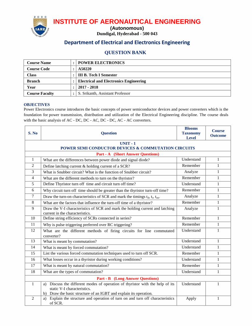
INSTITUTE OF AERONAUTICAL ENGINEERING (Autonomous)
Dundigal, Hyderabad - 500 043
Department of Electrical and Electronics Engineering
QUESTION BANK
Course Name : POWER ELECTRONICS
Course Code : A50220
Class : III B. Tech I Semester
Branch : Electrical and Electronics Engineering
Year : 2017 - 2018
Course Faculty : S. Srikanth, Assistant Professor
OBJECTIVES
Power Electronics course introduces the basic concepts of power semiconductor devices and power converters which is the
foundation for power transmission, distribution and utilization of the Electrical Engineering discipline. The course deals
with the basic analysis of AC - DC, DC - AC, DC - DC, AC - AC converters.
S. No Question
Blooms
Taxonomy
Level
Course
Outcome
UNIT - 1
POWER SEMI CONDUCTOR DEVICES & COMMUTATION CIRCUITS
Part - A (Short Answer Questions)
1 What are the differences between power diode and signal diode? Understand 1
2 Define latching current & holding current of a SCR? Remember 1
3 What is Snubber circuit? What is the function of Snubber circuit? Analyze 1
4 What are the different methods to turn on the thyristor? Remember 1
5 Define Thyristor turn off time and circuit turn off time? Understand 1
6 Why circuit turn off time should be greater than the thyristor turn-off time? Remember 1
7 Draw the turn-on characteristics of SCR and mark the timings td, tr, ton. Analyze 1
8 What are the factors that influence the turn-off time of a thyristor? Remember 1
9 Draw the V-I characteristics of SCR and mark the holding current and latching
current in the characteristics.
Analyze 1
10 Define string efficiency of SCRs connected in series? Remember 1
11 Why is pulse triggering preferred over RC triggering? Remember 1
12 What are the different methods of firing circuits for line commutated
converter?
Understand 1
13 What is meant by commutation? Understand 1
14 What is meant by forced commutation? Understand 1
15 List the various forced commutation techniques used to turn off SCR. Remember 1
16 What losses occur in a thyristor during working conditions? Understand 1
17 What is meant by natural commutation? Remember 1
18 What are the types of commutation? Understand 1
Part - B (Long Answer Questions)
1 a) Discuss the different modes of operation of thyristor with the help of its
static V-I characteristics.
b) Draw the basic structure of an IGBT and explain its operation.
Understand 1
2 a) Explain the structure and operation of turn on and turn off characteristics
of SCR.
Apply 1
S. No Question
Blooms
Taxonomy
Level
Course
Outcome
b) Describe the any two methods of turn-on mechanism of SCR.
c) Explain the turn off characteristics of SCR.
3 a) Explain the switching performance of BJT with relevant waveforms
indicating clearly the turn on, turn off times and their components.
b) Compare the performance characteristics of MOSFET with BJT.
Apply 1
4 What is commutation? What are the different types of commutation techniques?
Discuss and differentiate the natural commutation and forced commutation.
Understand 1
5 a) Draw the two transistor model of SCR and derive an expression for anode
current.
b) Describe the various methods of thyristor turn-on.
Apply 1
6 What is meant by triggering of SCR? What are the different types of triggering
circuits? Briefly discuss the R-C triggering and UJT triggering of SCR.
Understand 1
7 a) Explain the static and dynamic characteristics of SCR.
b) What are different types of ratings of SCR. Explain them.
Apply 1
8 a) Explain the necessity of series and parallel connection of SCRs.
b) What is String efficiency in series and parallel connections?
c) What are the problems arising in series and parallel connections.
Apply 1
9 a) What is the importance of Surge current rating of a thyristor, explain in
detail?
b) A thyristor has half-cycle surge current rating of 1000mA for a 50Hz
supply. Calculate its one-cycle surge current rating and i2t rating
Understand 1
10 a) Enlighten the simple SCR series inverter circuit employing class A-type commutation. With the help of important waveforms.
b) State the limitations of employing class A type commutation
Remember 1
11 a) Draw & explain the characteristics of SCR. What is the effect of gate
current on operation of SCR?
b) State the difference between GTO and conventional thyristor in terms of
commutation and also state any two advantages over conventional
Thyristor.
Understand 1
12 a) Draw the circuit diagram of Class B commutation. State the function of
each commutating components.
b) Draw and explain the circuit diagram of Class C commutation.
Apply 1
13 a) Define commutation. State the types of commutation.
b) Draw class D commutation method. Name commutating components. State
function of each commutating components
Understand 1
14 a) What are the requirements of pulse to trigger SCR successfully?
b) State the advantages of gate triggering methods of SCR.
Apply 1
15 a) Draw and explain the gate triggering characteristics of SCR.
b) Explain dv/dt triggering and light triggering of SCR.
Apply 1
Part – C (Analytical Questions)
1 A BJT has current gainβ=40. The load resistance RC=10Ω, dc supply voltageVcc=130V and input voltage to base circuit VB=10V. for VCES=1V and VBES=1.5V, calculate:
i. the value of RB for operation in the saturation state ii. the value of RB for an overdrive factor 5 iii. forced current gain
Apply
1
2 For an SCR the gate-cathode characteristic has a straight line slope of 130. For trigger source voltage of 15V and allowable gate power dissipation of 0.5 watts, compute the gate source resistance.
Apply 1
3 Latching current for an SCR, inserted in between a dc voltage source of 200V and the load is 100mA. Compute the minimum width of gate pulse current required to turn on this SCR in case the load consists of
i. L=0.2H,
ii. R=20Ω in series with L=0.2H and
iii. R=20Ω in series with L=2H
Apply 1
4 The trigger circuit of a thyristor has a source voltage of 15V and the load line
has a slope of -120V per ampere. The minimum gate current to turn on the
Apply 1
S. No Question
Blooms
Taxonomy
Level
Course
Outcome
SCR is 25mA. Compute
i. Source resistance required in the gate circuit
ii. The trigger voltage and trigger current for an average gate power
dissipation of 0.4 watts
5 An SCR has half cycle surge current rating of 3000A for 50Hz supply.
Calculate its one cycle surge current rating and I2t rating
Apply 1
6 SCRs with a rating of 1000V and 200A are available to be used in a string to handle 6kV and 1kA. Calculate the number of series and parallel units required in case de-rating factor is 0.1 and 0.2
Apply 1
7 It is required to operate 250A SCR in parallel with 350A SCR with their respective on state voltage drops of 1.6V and 1.2V. calculate the value of resistance to be inserted in series with each SCR so that the share the total load of 600A in proportion to their current ratings.
Apply 1
8 Class B commutation has C= 20µF and L=5µH. initial voltage across capacitor
is Vs=230V for a constant load current of 300A, calculate
i. Conduction time for the auxiliary thyristor
ii. Voltage across the main thyristor when it gets commutated and
iii. The circuit turn off time for the main thyristor
Apply 1
9 Class C commutation has Vs=200V, R1=10Ω and R2=100Ω, determine
i. Peak value of current through thyristors T1 and T2
ii. Value of capacitor C if each thyristor has turn off time of 40µs.
take a factor of safety 2.
Apply 1
10 In the complementary commutation circuit the load resistances R1 = R2 = 10Ω
and capacitor C = 10µF. The supply voltage is 100V. Determine the circuit
turnoff time.
Apply 1
11 SCRs with rating of 1100V and 210A are available to be used in a string to
handle 6.6kV and 1kA. Calculate the number of series and parallel units
required in case de-rating factor is (i) 0.1 and (ii) 0.2.
Apply 1
UNIT – II
AC-DC CONVERTERS (1-PHASE & 3-PHASE CONTROLLED RECTIFIERS)
Part - A (Short Answer Questions)
1 What is meant by phase controlled rectifier? Remember 2
2 Mention some of the applications of controlled rectifier. Remember 2
3 What is the function of freewheeling diode in controlled rectifier? Analyze 2
4 What are the advantages of freewheeling diode in a controlled in a controlled
rectifier?
Remember 2
5 What is meant by delay angle? Understand 2
6 What are the advantages of single phase bridge converter over single phase mid-point converter?
Remember 2
7 What is commutation angle or overlap angle? Remember 2
8 What are the different methods of firing circuits for line commutated
converter?
Understand 2
9 Give an expression for average voltage of single phase semi converters. Remember 2
10 Show the effect of the source inductance in full converter. Understand 2
11 What is meant by input power factor in controlled rectifier? Remember 2
12 Give an expression for average voltage of single phase Full Converter with R
load
Remember 2
13 How full converter operates in an inversion mode? Understand 2
14 What is phase control technique? Understand 2
15 What is six pulse converter? Write its advantages. Remember 2
16 Sketch the four quadrants in which the dual converter operates? Remember 2
17 Give the range of firing angles of a dual converter for all 4 quadrants. Remember 2
S. No Question
Blooms
Taxonomy
Level
Course
Outcome
18 Differences between non-circulating current mode & circulating current node
of a dual converter.
Understand 2
19 Give the relation between the firing angles of two converters in a dual
converter.
Remember 2
20 Give an expression for three phase full converter for a delay angle of 600 Remember 2
Part - B (Long Answer Questions)
1 Explain the operation of a single phase full wave mid-point converter with R-load with the help of circuit and output waveforms with respect to supply voltages.
Apply 2
2 a) Explain the operation of a single phase half wave converter for R-load with neat circuit diagram and necessary waveforms.
b) Obtain the output average voltage and current of a single phase half wave converter for R-load for α = 30
0.
Understand 2
3 a) Explain the operation of three phase fully controlled bridge converter with RL loads.
b) Illustrate in detail with discontinuous conduction mode with associated waveforms.
Understand 2
4 Describe the operation of a single phase two pulse midpoint converter with
relevant waveforms.
Apply 2
5 Derive the expressions for the following performance factors of single phase fully controlled bridge converter (a) input displacement factor (b) input power factor
(c) voltage ripple factor (d) active power input (e) Reactive power input
Apply 2
6 Describe the operation of a single phase two pulse midpoint converter with relevant waveforms. Derive an expression for average output voltage.
Apply 2
7 What are the features of Half-controlled converters over full controlled
converters?
Understand 2
8 a) Show that the effect of source inductance on the performance of single phase fully controlled converter is to present an equivalent resistance of Ls/π ohms in series with the internal rectifier voltage.
b) A single phase fully controlled converter is supplied at 220V, 50Hz. Determine the average load voltage for the following cases when the firing angle is 45
0 for purely resistive load.
Analyze 2
9 What do you mean by the requirement of reactive power for a converter? Why at all it is required, even for purely resistive load?
Understand 2
10 Explain the operation of dual converter with neat sketch. Apply 2
11 Explain the working of a single phase half wave controlled rectifier with R-L
load.
Apply 2
12 Derive the output voltage single phase full wave mid-point converter with R-
load for α= 450.
Apply 2
13 Derive an expression for average output voltage of a single phase two pulse
midpoint converter
Apply 2
14 Bring out the features of Free-wheeling diode used in converters. Understand 2
15 A single phase fully controlled bridge converter is supplied at 230V, 50Hz,
with source inductance of 2mH. Neglecting resistance voltage drop, when the
converter is operating at a firing angle of 45o and the load current is constant at
10A. Determine also the load voltage
Apply 2
Part – C (Analytical Questions)
1 A single phase transformer, with secondary voltage of 230V, 50Hz, delivers
power to load R=10Ω through a half-wave controlled rectifier circuit. For a
firing angle delay of 60o, determine (i) the rectifier efficiency (ii) form factor
(iii) voltage ripple factor (iv) transformer utilization factor and (v) PIV of
thyristor.
Apply 2
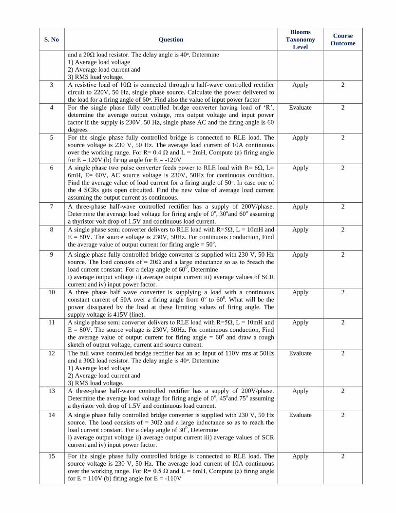
2 The full wave controlled bridge rectifier has an ac Input of 120V rms at 60Hz Evaluate 2
S. No Question
Blooms
Taxonomy
Level
Course
Outcome
and a 20Ω load resistor. The delay angle is 40ᵒ. Determine
1) Average load voltage
2) Average load current and
3) RMS load voltage.
3 A resistive load of 10Ω is connected through a half-wave controlled rectifier
circuit to 220V, 50 Hz, single phase source. Calculate the power delivered to
the load for a firing angle of 60ᵒ. Find also the value of input power factor
Apply 2
4 For the single phase fully controlled bridge converter having load of ‘R’,
determine the average output voltage, rms output voltage and input power
factor if the supply is 230V, 50 Hz, single phase AC and the firing angle is 60
degrees
Evaluate 2
5 For the single phase fully controlled bridge is connected to RLE load. The
source voltage is 230 V, 50 Hz. The average load current of 10A continuous
over the working range. For R= 0.4 Ω and L = 2mH, Compute (a) firing angle
for E = 120V (b) firing angle for E = -120V
Apply 2
6 A single phase two pulse converter feeds power to RLE load with R= 6Ω, L=
6mH, E= 60V, AC source voltage is 230V, 50Hz for continuous condition.
Find the average value of load current for a firing angle of 50ᵒ. In case one of
the 4 SCRs gets open circuited. Find the new value of average load current
assuming the output current as continuous.
Apply 2
7 A three-phase half-wave controlled rectifier has a supply of 200V/phase.
Determine the average load voltage for firing angle of 0o, 30
oand 60
o assuming
a thyristor volt drop of 1.5V and continuous load current.
Apply 2
8 A single phase semi converter delivers to RLE load with R=5Ω, L = 10mH and
E = 80V. The source voltage is 230V, 50Hz. For continuous conduction, Find
the average value of output current for firing angle = 50o.
Apply 2
9 A single phase fully controlled bridge converter is supplied with 230 V, 50 Hz
source. The load consists of = 20Ω and a large inductance so as to 5reach the
load current constant. For a delay angle of 600, Determine
i) average output voltage ii) average output current iii) average values of SCR
current and iv) input power factor.
Apply 2
10 A three phase half wave converter is supplying a load with a continuous
constant current of 50A over a firing angle from 0o to 60
0. What will be the
power dissipated by the load at these limiting values of firing angle. The
supply voltage is 415V (line).
Apply 2
11 A single phase semi converter delivers to RLE load with R=5Ω, L = 10mH and
E = 80V. The source voltage is 230V, 50Hz. For continuous conduction, Find
the average value of output current for firing angle = 60o
and draw a rough
sketch of output voltage, current and source current.
Apply 2
12 The full wave controlled bridge rectifier has an ac Input of 110V rms at 50Hz
and a 30Ω load resistor. The delay angle is 40ᵒ. Determine
1) Average load voltage
2) Average load current and
3) RMS load voltage.
Evaluate 2
13 A three-phase half-wave controlled rectifier has a supply of 200V/phase.
Determine the average load voltage for firing angle of 0o, 45
oand 75
o assuming
a thyristor volt drop of 1.5V and continuous load current.
Apply 2
14 A single phase fully controlled bridge converter is supplied with 230 V, 50 Hz
source. The load consists of = 30Ω and a large inductance so as to reach the
load current constant. For a delay angle of 300, Determine
i) average output voltage ii) average output current iii) average values of SCR
current and iv) input power factor.
Evaluate 2
15 For the single phase fully controlled bridge is connected to RLE load. The
source voltage is 230 V, 50 Hz. The average load current of 10A continuous
over the working range. For R= 0.5 Ω and L = 6mH, Compute (a) firing angle
for E = 110V (b) firing angle for E = -110V
Apply 2
S. No Question
Blooms
Taxonomy
Level
Course
Outcome
UNIT - III
DC-DC CONVERTERS (CHOPPERS)
Part - A (Short Answer Questions)
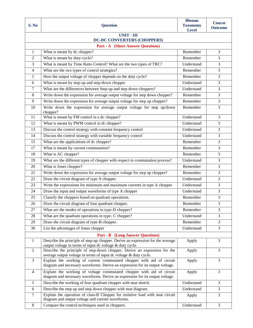
1 What is meant by dc chopper? Remember 3
2 What is meant by duty-cycle? Remember 3
3 What is meant by Time Ratio Control? What are the two types of TRC? Understand 3
4 What are the two types of control strategies? Remember 3
5 How the output voltage of chopper depends on the duty cycle? Remember 3
6 What is meant by step-up and step-down chopper Understand 3
7 What are the differences between Step-up and step down choppers? Understand 3
8 Write down the expression for average output voltage for step down chopper? Remember 3
9 Write down the expression for average output voltage for step up chopper? Remember 3
10 Write down the expression for average output voltage for step up/down
chopper?
Remember 3
11 What is meant by FM control in a dc chopper? Understand 3
12 What is meant by PWM control in dc chopper? Understand 3
13 Discuss the control strategy with constant frequency control Understand 3
14 Discuss the control strategy with variable frequency control Understand 3
15 What are the applications of dc chopper? Remember 3
17 What is meant by current commutation? Remember 3
18 What is AC chopper? Remember 3
19 What are the different types of chopper with respect to commutation process? Understand 3
20 What is Jones chopper? Remember 3
21 Write down the expression for average output voltage for step up chopper? Remember 3
22 Draw the circuit diagram of type A chopper. Understand 3
23 Write the expressions for minimum and maximum currents in type A chopper Understand 3
24 Draw the input and output waveforms of type A chopper Understand 3
25 Classify the choppers based on quadrant operations. Remember 3
26 Draw the circuit diagram of four quadrant chopper. Remember 3
27 What are the modes of operations in type-D chopper? Remember 3
28 What are the quadrant operations in type- C chopper? Understand 3
29 Draw the circuit diagram of type-B chopper. Remember 3
30 List the advantages of Jones chopper Understand 3
Part - B (Long Answer Questions)
1 Describe the principle of step-up chopper. Derive an expression for the average
output voltage in terms of input dc voltage & duty cycle.
Apply 3
2 Describe the principle of step-down chopper. Derive an expression for the
average output voltage in terms of input dc voltage & duty cycle.
Apply 3
3 Explain the working of current commutated chopper with aid of circuit
diagram and necessary waveforms. Derive an expression for its output voltage.
Apply 3
4 Explain the working of voltage commutated chopper with aid of circuit
diagram and necessary waveforms. Derive an expression for its output voltage.
Apply 3
5 Describe the working of four quadrant chopper with neat sketch. Understand 3
6 Describe the step up and step down chopper with neat diagram. Understand 3
7 Explain the operation of class-B Chopper for resistive load with neat circuit diagram and output voltage and current waveforms.
Apply 3
8 Compare the control techniques used in choppers. Understand 3
S. No Question
Blooms
Taxonomy
Level
Course
Outcome
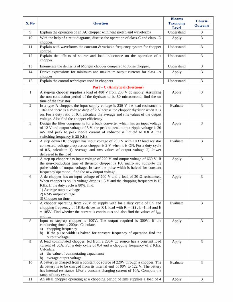
9 Explain the operation of an AC chopper with neat sketch and waveforms Understand 3
10 With the help of circuit diagrams, discuss the operation of class-C and class –D
chopper.
Apply 3
11 Explain with waveforms the constant & variable frequency system for chopper
control.
Understand 3
12 Explain the effects of source and load inductance on the operation of a
chopper.
Understand 3
13 Enumerate the demerits of Morgan chopper compared to Jones chopper. Understand 3
14 Derive expressions for minimum and maximum output currents for class –A
chopper
Apply 3
15 Explain the control techniques used in choppers Understand 3
Part – C (Analytical Questions)
1 A step-up chopper supplies a load of 480 V from 230 V dc supply. Assuming
the non conduction period of the thyristor to be 50 microsecond, find the on
time of the thyristor
Apply 3
2 In a type A chopper, the input supply voltage is 230 V the load resistance is
10Ω and there is a voltage drop of 2 V across the chopper thyristor when it is
on. For a duty ratio of 0.4, calculate the average and rms values of the output
voltage. Also find the chopper efficiency
Evaluate 3
3 Design the filter components for a buck converter which has an input voltage
of 12 V and output voltage of 5 V. the peak to peak output ripple voltage is 20
mV and peak to peak ripple current of inductor is limited to 0.8 A. the
switching frequency is 25 KHz
Apply 3
4 A step down DC chopper has input voltage of 230 V with 10 Ω load resistor
connected, voltage drop across chopper is 2 V when it is ON. For a duty cycle
of 0.5, calculate: 1) Average and rms values of output voltage 2) Power
delivered to the load
Evaluate 3
5 A step up chopper has input voltage of 220 V and output voltage of 660 V. If
the non-conducting time of thyristor chopper is 100 micro sec compute the
pulse width of output voltage. In case the pulse width is halved for constant
frequency operation , find the new output voltage
Apply 3
6 A dc chopper has an input voltage of 200 V and a load of 20 Ω resistances.
When chopper is on, its voltage drop is 1.5 V and the chopping frequency is 10
KHz. If the duty cycle is 80%, find.
1) Average output voltage
2) RMS output voltage
3) Chopper on time
Apply 3
7 A chopper operating from 220V dc supply with for a duty cycle of 0.5 and
chopping frequency of 1KHz drives an R L load with R = 1Ω , L=1mH and E
= 105V. Find whether the current is continuous and also find the values of Imax
and Imin.
Evaluate 3
8 Input to step-up chopper is 100V. The output required is 300V. If the conducting time is 200µs. Calculate. a) chopping frequency b) If the pulse width is halved for constant frequency of operation find the
output voltage.
Apply 3
9 A load commutated chopper, fed from a 230V dc source has a constant load current of 50A. For a duty cycle of 0.4 and a chopping frequency of 2 KHz, Calculate. a) the value of commutating capacitance
b) average output voltage
Apply 3
10 A battery is charged from a constant dc source of 220V through a chopper. The dc battery is to be charged from its internal emf of 90V to 122 V. The battery has internal resistance 1.For a constant charging current of 10A. Compute the range of duty cycle.
Evaluate 3
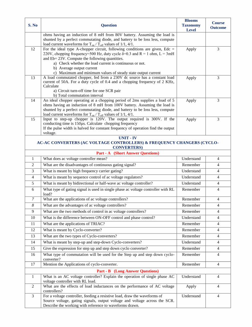
11 An ideal chopper operating at a chopping period of 2ms supplies a load of 4 Apply 3
S. No Question
Blooms
Taxonomy
Level
Course
Outcome
ohms having an induction of 8 mH from 80V battery. Assuming the load is shunted by a perfect commutating diode, and battery to be loss less, compute load current waveforms for Ton / Toff values of 1/1, 4/1.
12 For the ideal type A-chopper circuit, following conditions are given, Edc =
220V, chopping frequency=500 Hz, duty cycle δ=0.3 and R = 1 ohm, L = 3mH
and Eb= 23V. Compute the following quantities.
a) Check whether the load current is continuous or not.
b) Average output current
c) Maximum and minimum values of steady state output current
Apply 3
13 A load commutated chopper, fed from a 230V dc source has a constant load current of 50A. For a duty cycle of 0.4 and a chopping frequency of 2 KHz, Calculate
a) Circuit turn-off time for one SCR pair
b) Total commutation interval
Apply 3
14 An ideal chopper operating at a chopping period of 2ms supplies a load of 5 ohms having an induction of 8 mH from 100V battery. Assuming the load is shunted by a perfect commutating diode, and battery to be loss less, compute
load current waveforms for Ton / Toff values of 1/1, 4/1.
Apply 3
15 Input to step-up chopper is 120V. The output required is 300V. If the conducting time is 150µs. Calculate chopping frequency
If the pulse width is halved for constant frequency of operation find the output
voltage.
Apply 3
UNIT - IV
AC-AC CONVERTERS (AC VOLTAGE CONTROLLERS) & FREQUENCY CHANGERS (CYCLO-
CONVERTERS)
Part - A (Short Answer Questions)
1 What does ac voltage controller mean? Understand 4
2 What are the disadvantages of continuous gating signal? Remember 4
3 What is meant by high frequency carrier gating? Understand 4
4 What is meant by sequence control of ac voltage regulators? Understand 4
5 What is meant by bidirectional or half-wave ac voltage controller? Understand 4
6 What type of gating signal is used in single phase ac voltage controller with RL
load?
Remember 4
7 What are the applications of ac voltage controllers? Remember 4
8 What are the advantages of ac voltage controllers? Remember 4
9 What are the two methods of control in ac voltage controllers? Remember 4
10 What is the difference between ON-OFF control and phase control? Understand 4
11 What are the applications of TRIAC? Remember 4
12 What is meant by Cyclo-converter? Remember 4
13 What are the two types of Cyclo-converters? Remember 4
14 What is meant by step-up and step-down Cyclo-converters? Understand 4
15 Give the expression for step up and step down cyclo converter? Remember 4
16 What type of commutation will be used for the Step up and step down cyclo-
converter?
Remember 4
17 Mention the Applications of cyclo-converter. Remember 4
Part - B (Long Answer Questions)
1 What is an AC voltage controller? Explain the operation of single phase AC
voltage controller with RL load.
Understand 4
2 What are the effects of load inductances on the performance of AC voltage
controllers?
Apply 4
3 For a voltage controller, feeding a resistive load, draw the waveforms of
Source voltage, gating signals, output voltage and voltage across the SCR.
Describe the working with reference to waveforms drawn.
Understand 4
S. No Question
Blooms
Taxonomy
Level
Course
Outcome
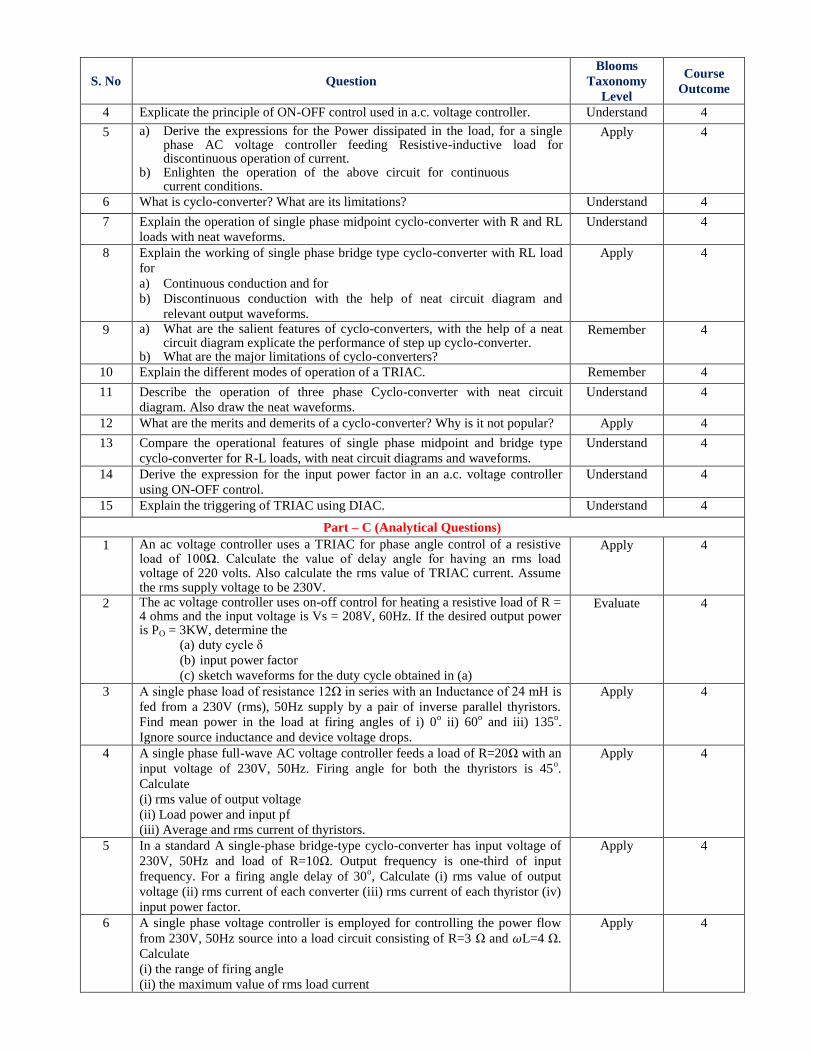
4 Explicate the principle of ON-OFF control used in a.c. voltage controller. Understand 4
5 a) Derive the expressions for the Power dissipated in the load, for a single phase AC voltage controller feeding Resistive-inductive load for discontinuous operation of current.
b) Enlighten the operation of the above circuit for continuous current conditions.
Apply 4
6 What is cyclo-converter? What are its limitations? Understand 4
7 Explain the operation of single phase midpoint cyclo-converter with R and RL
loads with neat waveforms.
Understand 4
8 Explain the working of single phase bridge type cyclo-converter with RL load
for a) Continuous conduction and for
b) Discontinuous conduction with the help of neat circuit diagram and
relevant output waveforms.
Apply 4
9 a) What are the salient features of cyclo-converters, with the help of a neat circuit diagram explicate the performance of step up cyclo-converter.
b) What are the major limitations of cyclo-converters?
Remember 4
10 Explain the different modes of operation of a TRIAC. Remember 4
11 Describe the operation of three phase Cyclo-converter with neat circuit
diagram. Also draw the neat waveforms.
Understand 4
12 What are the merits and demerits of a cyclo-converter? Why is it not popular? Apply 4
13 Compare the operational features of single phase midpoint and bridge type
cyclo-converter for R-L loads, with neat circuit diagrams and waveforms.
Understand 4
14 Derive the expression for the input power factor in an a.c. voltage controller
using ON-OFF control.
Understand 4
15 Explain the triggering of TRIAC using DIAC. Understand 4
Part – C (Analytical Questions)
1 An ac voltage controller uses a TRIAC for phase angle control of a resistive load of 100Ω. Calculate the value of delay angle for having an rms load voltage of 220 volts. Also calculate the rms value of TRIAC current. Assume the rms supply voltage to be 230V.
Apply 4
2 The ac voltage controller uses on-off control for heating a resistive load of R = 4 ohms and the input voltage is Vs = 208V, 60Hz. If the desired output power is PO = 3KW, determine the
(a) duty cycle δ
(b) input power factor
(c) sketch waveforms for the duty cycle obtained in (a)
Evaluate 4
3 A single phase load of resistance 12Ω in series with an Inductance of 24 mH is
fed from a 230V (rms), 50Hz supply by a pair of inverse parallel thyristors.
Find mean power in the load at firing angles of i) 0o ii) 60
o and iii) 135
o.
Ignore source inductance and device voltage drops.
Apply 4
4 A single phase full-wave AC voltage controller feeds a load of R=20Ω with an
input voltage of 230V, 50Hz. Firing angle for both the thyristors is 45o.
Calculate
(i) rms value of output voltage
(ii) Load power and input pf
(iii) Average and rms current of thyristors.
Apply 4
5 In a standard A single-phase bridge-type cyclo-converter has input voltage of
230V, 50Hz and load of R=10Ω. Output frequency is one-third of input
frequency. For a firing angle delay of 30o, Calculate (i) rms value of output
voltage (ii) rms current of each converter (iii) rms current of each thyristor (iv)
input power factor.
Apply 4
6 A single phase voltage controller is employed for controlling the power flow
from 230V, 50Hz source into a load circuit consisting of R=3 Ω and L=4 Ω.
Calculate
(i) the range of firing angle
(ii) the maximum value of rms load current
Apply 4
S. No Question
Blooms
Taxonomy
Level
Course
Outcome
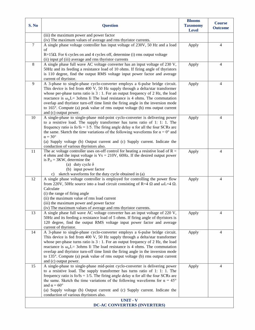
(iii) the maximum power and power factor
(iv) The maximum values of average and rms thyristor currents.
7 A single phase voltage controller has input voltage of 230V, 50 Hz and a load
of
R=15Ω. For 6 cycles on and 4 cycles off, determine (i) rms output voltage
(ii) input pf (iii) average and rms thyristor currents
Apply 4
8 A single phase full wave AC voltage converter has an input voltage of 230 V,
50Hz and its feeding a resistance load of 10 ohms. If firing angle of thyristors
is 110 degree, find the output RMS voltage input power factor and average
current of thyristor.
Apply 4
9 A 3-phase to single-phase cyclo-converter employs a 6-pulse bridge circuit.
This device is fed from 400 V, 50 Hz supply through a delta/star transformer
whose per-phase turns ratio is 3 : 1. For an output frequency of 2 Hz, the load
reactance is L= 3ohms Ii The load resistance is 4 ohms. The commutation
overlap and thyristor turn-off time limit the firing angle in the inversion mode
to 165°. Compute (a) peak value of rms output voltage (b) rms output current
and (c) output power.
Apply 4
10 A single-phase to single-phase mid-point cyclo-converter is delivering power
to a resistive load. The supply transformer has turns ratio of 1: 1: 1. The
frequency ratio is fo/fs = 1/5. The firing angle delay α for all the four SCRs are
the same. Sketch the time variations of the following waveforms for α = 0° and
α = 30°
(a) Supply voltage (b) Output current and (c) Supply current. Indicate the
conduction of various thyristors also.
Apply 4
11 The ac voltage controller uses on-off control for heating a resistive load of R = 4 ohms and the input voltage is Vs = 210V, 60Hz. If the desired output power is PO = 3KW, determine the
(a) duty cycle δ
(b) input power factor
c) sketch waveforms for the duty cycle obtained in (a)
Apply 4
12 A single phase voltage controller is employed for controlling the power flow
from 220V, 50Hz source into a load circuit consisting of R=4 Ω and L=4 Ω.
Calculate
(i) the range of firing angle
(ii) the maximum value of rms load current
(iii) the maximum power and power factor
(iv) The maximum values of average and rms thyristor currents.
Apply 4
13 A single phase full wave AC voltage converter has an input voltage of 220 V,
50Hz and its feeding a resistance load of 5 ohms. If firing angle of thyristors is
120 degree, find the output RMS voltage input power factor and average
current of thyristor.
Apply 4
14 A 3-phase to single-phase cyclo-converter employs a 6-pulse bridge circuit.
This device is fed from 400 V, 50 Hz supply through a delta/star transformer
whose per-phase turns ratio is 3 : 1. For an output frequency of 2 Hz, the load
reactance is L= 3ohms Ii The load resistance is 4 ohms. The commutation
overlap and thyristor turn-off time limit the firing angle in the inversion mode
to 135°. Compute (a) peak value of rms output voltage (b) rms output current
and (c) output power.
Apply 4
15 A single-phase to single-phase mid-point cyclo-converter is delivering power
to a resistive load. The supply transformer has turns ratio of 1: 1: 1. The
frequency ratio is fo/fs = 1/5. The firing angle delay α for all the four SCRs are
the same. Sketch the time variations of the following waveforms for α = 45°
and α = 60°
(a) Supply voltage (b) Output current and (c) Supply current. Indicate the
conduction of various thyristors also.
Apply 4
UNIT - V
DC-AC CONVERTERS (INVERTERS)
S. No Question
Blooms
Taxonomy
Level
Course
Outcome
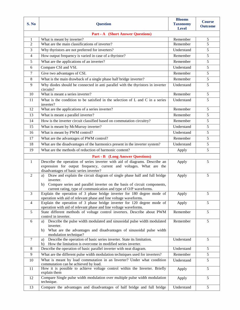
Part - A (Short Answer Questions)
1 What is meant by inverter? Remember 5
2 What are the main classifications of inverter? Remember 5
3 Why thyristors are not preferred for inverters? Understand 5
4 How output frequency is varied in case of a thyristor? Remember 5
5 What are the applications of an inverter? Remember 5
6 Compare CSI and VSI. Understand 5
7 Give two advantages of CSI. Remember 5
8 What is the main drawback of a single phase half bridge inverter? Remember 5
9 Why diodes should be connected in anti parallel with the thyristors in inverter
circuits?
Understand 5
10 What is meant a series inverter? Remember 5
11 What is the condition to be satisfied in the selection of L and C in a series
inverter?
Understand 5
12 What are the applications of a series inverter? Remember 5
13 What is meant a parallel inverter? Remember 5
14 How is the inverter circuit classified based on commutation circuitry? Remember 5
15 What is meant by McMurray inverter? Understand 5
16 What is meant by PWM control? Understand 5
17 What are the advantages of PWM control? Remember 5
18 What are the disadvantages of the harmonics present in the inverter system? Understand 5
19 What are the methods of reduction of harmonic content? Apply 5
Part - B (Long Answer Questions)
1 Describe the operation of series inverter with aid of diagrams. Describe an
expression for output frequency, current and voltages. What are the
disadvantages of basic series inverter?
Apply 5
2 a) Draw and explain the circuit diagram of single phase half and full bridge
inverter.
b) Compare series and parallel inverter on the basis of circuit components,
current rating, type of communication and type of O/P waveforms.
Apply 5
3 Explain the operation of 3 phase bridge inverter for 180 degree mode of
operation with aid of relevant phase and line voltage waveforms.
Apply 5
4 Explain the operation of 3 phase bridge inverter for 120 degree mode of
operation with aid of relevant phase and line voltage waveforms.
Apply 5
5 State different methods of voltage control inverters. Describe about PWM
control in inverter.
Remember 5
6 a) Describe the pulse width modulated and sinusoidal pulse width modulated
inverter.
b) What are the advantages and disadvantages of sinusoidal pulse width
modulation technique?
Remember 5
7 a) Describe the operation of basic series inverter. State its limitation.
b) How the limitation is overcome in modified series inverter.
Understand 5
8 Describe the operation of basic parallel inverter with neat diagram. Understand 5
9 What are the different pulse width modulation techniques used for inverters? Remember 5
10 What is meant by load commutation in an Inverter? Under what condition commutation can be achieved by load.
Understand 5
11 How it is possible to achieve voltage control within the Inverter. Briefly explain them
Apply 5
12 Compare Single pulse width modulation over multiple pulse width modulation technique.
Apply 5
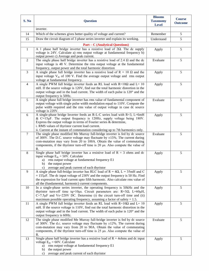
13 Compare the advantages and disadvantages of half bridge and full bridge Understand 5
S. No Question
Blooms
Taxonomy
Level
Course
Outcome
inverter.
14 Which of the schemes gives better quality of voltage and current? Remember 5
15 Draw the circuit diagram of 3 phase series inverter and explain its working. Understand 5
Part – C (Analytical Questions)
1 A 1 phase half bridge inverter has a resistive load of 2Ω. The dc supply voltage is 24V. Calculate a) rms output voltage at fundamental frequency b) output power c) Average and peak current.
Apply 5
2 The single phase half bridge inverter has a resistive load of 2.4 Ω and the dc
input voltage is 48 V. Determine the rms output voltage at the fundamental
frequency, output power and the total harmonic distortion
Evaluate 5
3 A single phase full bridge inverter has a resistive load of R = 10 Ω and the
input voltage Vdc of 100 V. Find the average output voltage and rms output
voltage at fundamental frequency.
Apply 5
4 A single PWM full bridge inverter feeds an RL load with R=10Ω and L= 10
mH. If the source voltage is 120V, find out the total harmonic distortion in the
output voltage and in the load current. The width of each pulse is 120° and the
output frequency is 50Hz.
Apply 5
5 A single phase full bridge inverter has rms value of fundamental component of output voltage with single pulse width modulation equal to 110V. Compute the pulse width required and the rms value of output voltage in case dc source voltage is 220V.
Evaluate 5
6 A single-phase bridge Inverter feeds an R-L-C series load with R=3, L=6mH & C=15μF. The output frequency is 120Hz, supply voltage being 180V. Express the output voltage in terms of Fourier series & determine, i. RMS values of thyristor current load current.
ii. Current at the instant of commutation considering up to 7th harmonics only.
Apply 5
7 The single phase modified Me Murray full-bridge inverter is fed by dc source of 300V. The D.C. source voltage may fluctuate by ±15%. The current during com-mutation may vary from 20 to 100A. Obtain the value of commutating components, if the thyristor turn-off time is 20 μs. Also compute the value of R.
Evaluate 5
8 Single phase half bridge inverter has a resistive load of R = 3 ohms and dc input voltage Edc = 50V. Calculate
a) rms output voltage at fundamental frequency E1 b) the output power
c) average and peak current of each thyristor
Apply 5
9 A single phase full-bridge inverter has RLC load of R = 4Ω, L = 35mH and C
= 155μF. The dc input voltage of 230V and the output frequency is 50 Hz. Find
the expression for load current upto fifth harmonic. Also calculate rms value of
all the (fundamental, harmonic) current components.
Apply 5
10 In a single-phase series inverter, the operating frequency is 50kHz and the
thyristor turn-off time tq=10μs. Circuit parameters are: R=3Ω, L=60μH,
C=7.5μF and Vs=220V DC. Determine (i) the circuit turn-off time and (ii)
maximum possible operating frequency, assuming a factor of safety = 1.5.
Apply 5
11 A single PWM full bridge inverter feeds an RL load with R=10Ω and L= 10
mH. If the source voltage is 110V, find out the total harmonic distortion in the
output voltage and in the load current. The width of each pulse is 120° and the
output frequency is 60Hz.
Apply 5
12 The single phase modified Me Murray full-bridge inverter is fed by dc source of 300V. The d.c. source voltage may fluctuate by ±12%. The current during com-mutation may vary from 20 to 90A. Obtain the value of commutating components, if the thyristor turn-off time is 25 μs. Also compute the value of R.
Evaluate 5
13 Single phase half bridge inverter has a resistive load of R = 4ohms and dc input voltage Edc = 60V. Calculate
a) rms output voltage at fundamental frequency E1 b) the output power
c) average and peak current of each thyristor
Apply 5
S. No Question
Blooms
Taxonomy
Level
Course
Outcome
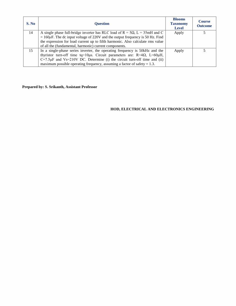
14 A single phase full-bridge inverter has RLC load of R = 5Ω, L = 35mH and C
= 160μF. The dc input voltage of 220V and the output frequency is 50 Hz. Find
the expression for load current up to fifth harmonic. Also calculate rms value
of all the (fundamental, harmonic) current components.
Apply 5
15 In a single-phase series inverter, the operating frequency is 50kHz and the
thyristor turn-off time tq=10μs. Circuit parameters are: R=4Ω, L=60μH,
C=7.5μF and Vs=210V DC. Determine (i) the circuit turn-off time and (ii)
maximum possible operating frequency, assuming a factor of safety = 1.3.
Apply 5
Prepared by: S. Srikanth, Assistant Professor
HOD, ELECTRICAL AND ELECTRONICS ENGINEERING


![· What do you understand by commutation of SCR. Explain class C commutation with the help of waveforms. Design the biggening circuit for SCR using U] T. The UJT](https://img.pdfslide.net/doc/110x75/5acf08ec7f8b9ad24f8bf205/do-you-understand-by-commutation-of-scr-explain-class-c-commutation-with-the-help.jpg)