Embed Size (px)
Citation preview
A301-85-880Issue M
Manor Royal, Crawley, West Sussex, RH10 2LW, UKTelephone: +44 (0) 1293 528844 Fax: +44 (0) 1293 533453http://www.bocedwards.com
QMB Mechanical Booster Pumps
Description Item Number
QMB250F Mechanical Booster Pump, 50 Hz A301-85-905QMB250F Mechanical Booster Pump, 60 Hz A301-86-905QMB500F Mechanical Booster Pump, 50 Hz A302-85-905QMB500F Mechanical Booster Pump, 60 Hz A302-86-905QMB1200F Mechanical Booster Pump, 50 Hz A305-85-905QMB1200F Mechanical Booster Pump, 60 Hz A305-86-905
Instruction Manual

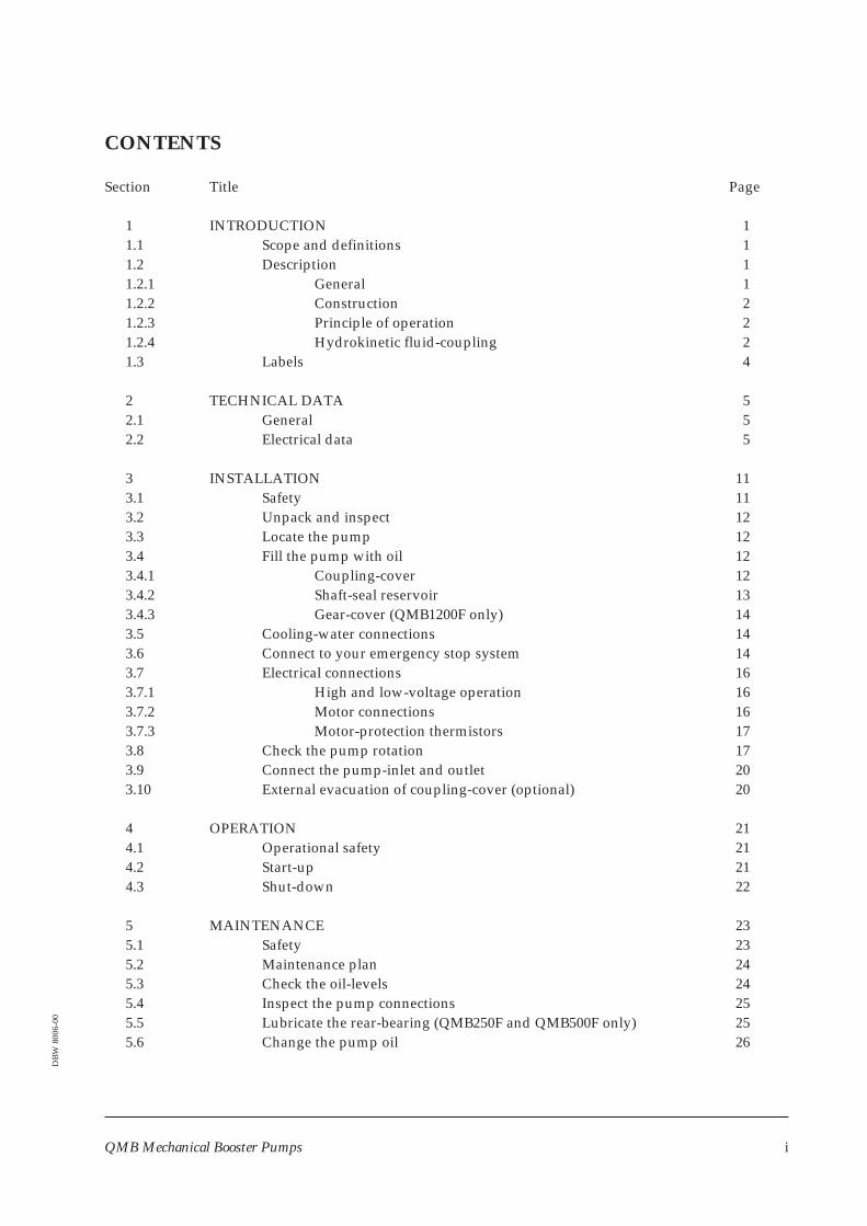
CONTENTS
Section Title Page
1 INTRODUCTION 11.1 Scope and definitions 11.2 Description 11.2.1 General 11.2.2 Construction 21.2.3 Principle of operation 21.2.4 Hydrokinetic fluid-coupling 21.3 Labels 4
2 TECHNICAL DATA 52.1 General 52.2 Electrical data 5
3 INSTALLATION 113.1 Safety 113.2 Unpack and inspect 123.3 Locate the pump 123.4 Fill the pump with oil 123.4.1 Coupling-cover 123.4.2 Shaft-seal reservoir 133.4.3 Gear-cover (QMB1200F only) 143.5 Cooling-water connections 143.6 Connect to your emergency stop system 143.7 Electrical connections 163.7.1 High and low-voltage operation 163.7.2 Motor connections 163.7.3 Motor-protection thermistors 173.8 Check the pump rotation 173.9 Connect the pump-inlet and outlet 203.10 External evacuation of coupling-cover (optional) 20
4 OPERATION 214.1 Operational safety 214.2 Start-up 214.3 Shut-down 22
5 MAINTENANCE 235.1 Safety 235.2 Maintenance plan 245.3 Check the oil-levels 245.4 Inspect the pump connections 255.5 Lubricate the rear-bearing (QMB250F and QMB500F only) 255.6 Change the pump oil 26
QMB Mechanical Booster Pumps i
DB
W80
06-0
0
Section Title Page
6 STORAGE AND DISPOSAL 286.1 Storage 286.2 Disposal 28
7 SERVICE, SPARES AND ACCESSORIES 297.1 Introduction 297.2 Service 297.3 Spares 297.4 Accessories 307.4.1 QMB Booster Frames 307.4.2 QMB Booster Frame Connection Kits 307.4.3 QMB Booster Frame Acoustic Enclosures 307.4.4 QMB to QMKII Connection Kits 31
RETURN OF BOC EDWARDS EQUIPMENT
Illustrations
Figure Title Page
1 QMB Mechanical Booster Pumps (part cut-away) 32 Labels on the QMB pump 43 QMB250F dimensions 74 QMB500F dimensions 85 QMB1200F dimensions 86 Typical pumping speed for QDP40 and QMB250F pumping combinations 97 Typical pumping speed for QDP80 and QMB250F pumping combinations 98 Typical pumping speed for QDP80 and QMB500F pumping combinations 109 Typical pumping speed for QDP80 and QMB1200F pumping combinations 1010 Sight-glasses 1311 Schematic diagram of the emergency stop system 1512 QMB250/500F low-voltage configuration 1813 QMB250/500F high-voltage configuration 1814 QMB1200F low-voltage configuration 1915 QMB1200F high-voltage configuration 1916 Lubricate the rear bearing (QMB250F and QMB500F only) 27
Tables
Table Title Page
1 Full load current ratings 52 Technical data 63 Maintenance plan 24
ii QMB Mechanical Booster Pumps
Associated publications
Publication title Publication Number
Vacuum pump and vacuum system safety P300-20-000QMB Booster Connection Kits A528-31-880QMB Booster Frames A528-37-880QMB Booster Frame Connection Kits A528-65-880QMB Booster Frame Acoustic Enclosure A528-70-880
QMB Mechanical Booster Pumps iii

(This page deliberately left blank)
iv QMB Mechanical Booster Pumps
1 INTRODUCTION
1.1 Scope and definitions
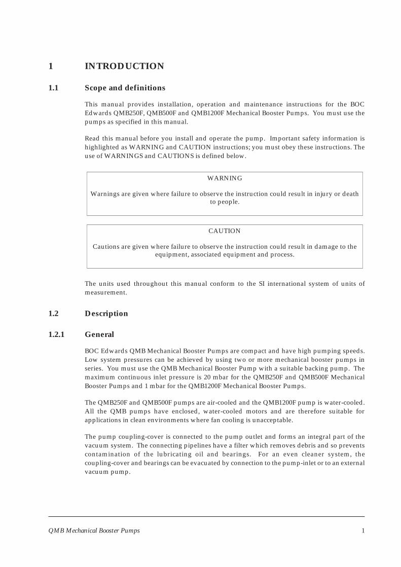
This manual provides installation, operation and maintenance instructions for the BOCEdwards QMB250F, QMB500F and QMB1200F Mechanical Booster Pumps. You must use thepumps as specified in this manual.
Read this manual before you install and operate the pump. Important safety information ishighlighted as WARNING and CAUTION instructions; you must obey these instructions. Theuse of WARNINGS and CAUTIONS is defined below.
WARNING
Warnings are given where failure to observe the instruction could result in injury or deathto people.
CAUTION
Cautions are given where failure to observe the instruction could result in damage to theequipment, associated equipment and process.
The units used throughout this manual conform to the SI international system of units ofmeasurement.
1.2 Description
1.2.1 General
BOC Edwards QMB Mechanical Booster Pumps are compact and have high pumping speeds.Low system pressures can be achieved by using two or more mechanical booster pumps inseries. You must use the QMB Mechanical Booster Pump with a suitable backing pump. Themaximum continuous inlet pressure is 20 mbar for the QMB250F and QMB500F MechanicalBooster Pumps and 1 mbar for the QMB1200F Mechanical Booster Pumps.
The QMB250F and QMB500F pumps are air-cooled and the QMB1200F pump is water-cooled.All the QMB pumps have enclosed, water-cooled motors and are therefore suitable forapplications in clean environments where fan cooling is unacceptable.
The pump coupling-cover is connected to the pump outlet and forms an integral part of thevacuum system. The connecting pipelines have a filter which removes debris and so preventscontamination of the lubricating oil and bearings. For an even cleaner system, thecoupling-cover and bearings can be evacuated by connection to the pump-inlet or to an externalvacuum pump.
QMB Mechanical Booster Pumps 1
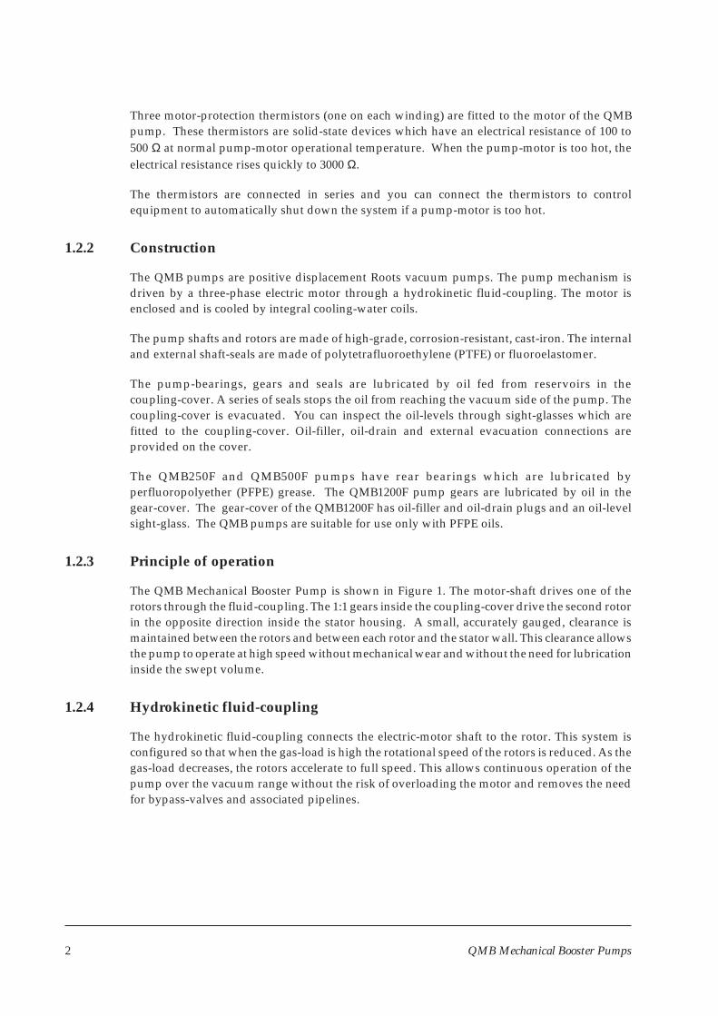
Three motor-protection thermistors (one on each winding) are fitted to the motor of the QMBpump. These thermistors are solid-state devices which have an electrical resistance of 100 to500 Ω at normal pump-motor operational temperature. When the pump-motor is too hot, theelectrical resistance rises quickly to 3000 Ω.
The thermistors are connected in series and you can connect the thermistors to controlequipment to automatically shut down the system if a pump-motor is too hot.
1.2.2 Construction
The QMB pumps are positive displacement Roots vacuum pumps. The pump mechanism isdriven by a three-phase electric motor through a hydrokinetic fluid-coupling. The motor isenclosed and is cooled by integral cooling-water coils.
The pump shafts and rotors are made of high-grade, corrosion-resistant, cast-iron. The internaland external shaft-seals are made of polytetrafluoroethylene (PTFE) or fluoroelastomer.
The pump-bearings, gears and seals are lubricated by oil fed from reservoirs in thecoupling-cover. A series of seals stops the oil from reaching the vacuum side of the pump. Thecoupling-cover is evacuated. You can inspect the oil-levels through sight-glasses which arefitted to the coupling-cover. Oil-filler, oil-drain and external evacuation connections areprovided on the cover.
The QMB250F and QMB500F pumps have rear bearings which are lubricated byperfluoropolyether (PFPE) grease. The QMB1200F pump gears are lubricated by oil in thegear-cover. The gear-cover of the QMB1200F has oil-filler and oil-drain plugs and an oil-levelsight-glass. The QMB pumps are suitable for use only with PFPE oils.
1.2.3 Principle of operation
The QMB Mechanical Booster Pump is shown in Figure 1. The motor-shaft drives one of therotors through the fluid-coupling. The 1:1 gears inside the coupling-cover drive the second rotorin the opposite direction inside the stator housing. A small, accurately gauged, clearance ismaintained between the rotors and between each rotor and the stator wall. This clearance allowsthe pump to operate at high speed without mechanical wear and without the need for lubricationinside the swept volume.
1.2.4 Hydrokinetic fluid-coupling
The hydrokinetic fluid-coupling connects the electric-motor shaft to the rotor. This system isconfigured so that when the gas-load is high the rotational speed of the rotors is reduced. As thegas-load decreases, the rotors accelerate to full speed. This allows continuous operation of thepump over the vacuum range without the risk of overloading the motor and removes the needfor bypass-valves and associated pipelines.
2 QMB Mechanical Booster Pumps
QM
BM
echanicalBooster
Pum
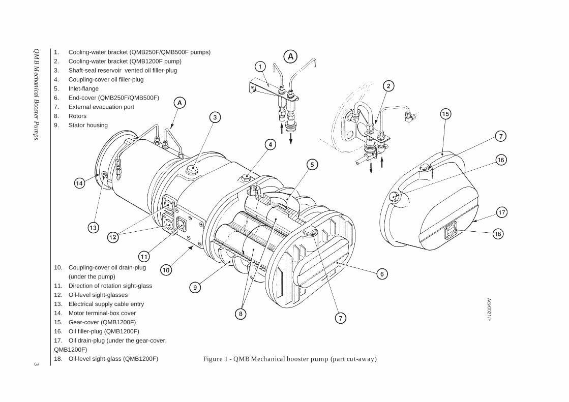
ps3 Figure 1 - QMB Mechanical booster pump (part cut-away)
10. Coupling-cover oil drain-plug
(under the pump)
11. Direction of rotation sight-glass
12. Oil-level sight-glasses
13. Electrical supply cable entry
14. Motor terminal-box cover
15. Gear-cover (QMB1200F)
16. Oil filler-plug (QMB1200F)
17. Oil drain-plug (under the gear-cover,
QMB1200F)
18. Oil-level sight-glass (QMB1200F)
1. Cooling-water bracket (QMB250F/QMB500F pumps)
2. Cooling-water bracket (QMB1200F pump)
3. Shaft-seal reservoir vented oil filler-plug
4. Coupling-cover oil filler-plug
5. Inlet-flange
6. End-cover (QMB250F/QMB500F)
7. External evacuation port
8. Rotors
9. Stator housing
1.3 Labels
Labels are fitted to the QMB pump in order to:
• Identify components.
• Define required installation/operation/maintenance procedures.
• Identify safety hazards.
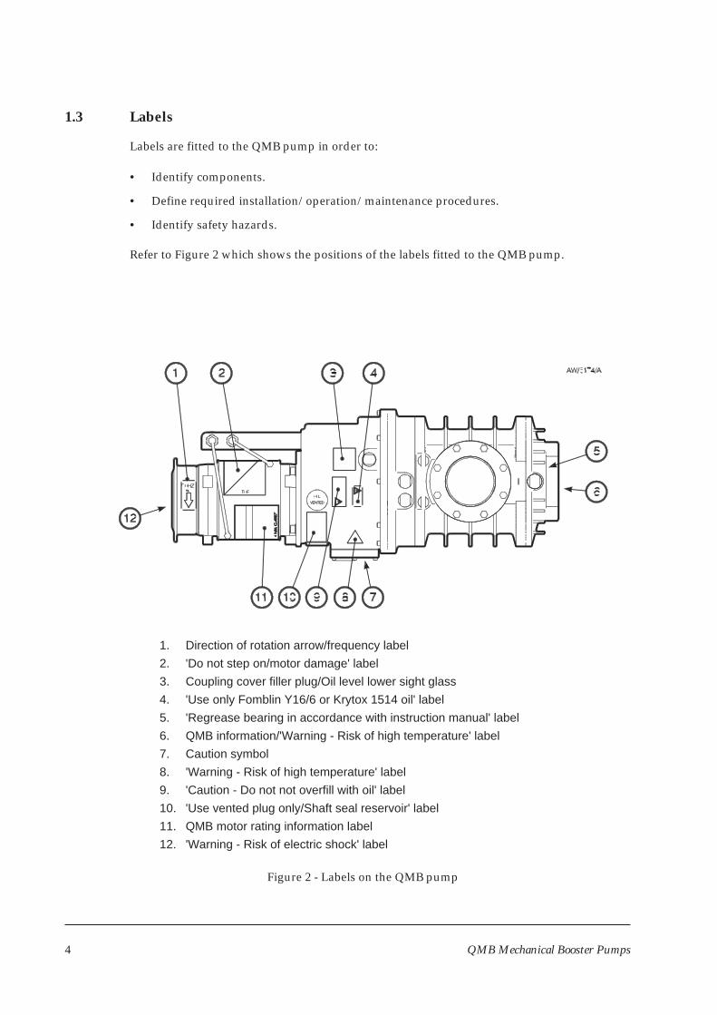
Refer to Figure 2 which shows the positions of the labels fitted to the QMB pump.
4 QMB Mechanical Booster Pumps
Figure 2 - Labels on the QMB pump
1. Direction of rotation arrow/frequency label
2. 'Do not step on/motor damage' label
3. Coupling cover filler plug/Oil level lower sight glass
4. 'Use only Fomblin Y16/6 or Krytox 1514 oil' label
5. 'Regrease bearing in accordance with instruction manual' label
6. QMB information/'Warning - Risk of high temperature' label
7. Caution symbol
8. 'Warning - Risk of high temperature' label
9. 'Caution - Do not not overfill with oil' label
10. 'Use vented plug only/Shaft seal reservoir' label
11. QMB motor rating information label
12. 'Warning - Risk of electric shock' label
2 TECHNICAL DATA
2.1 General
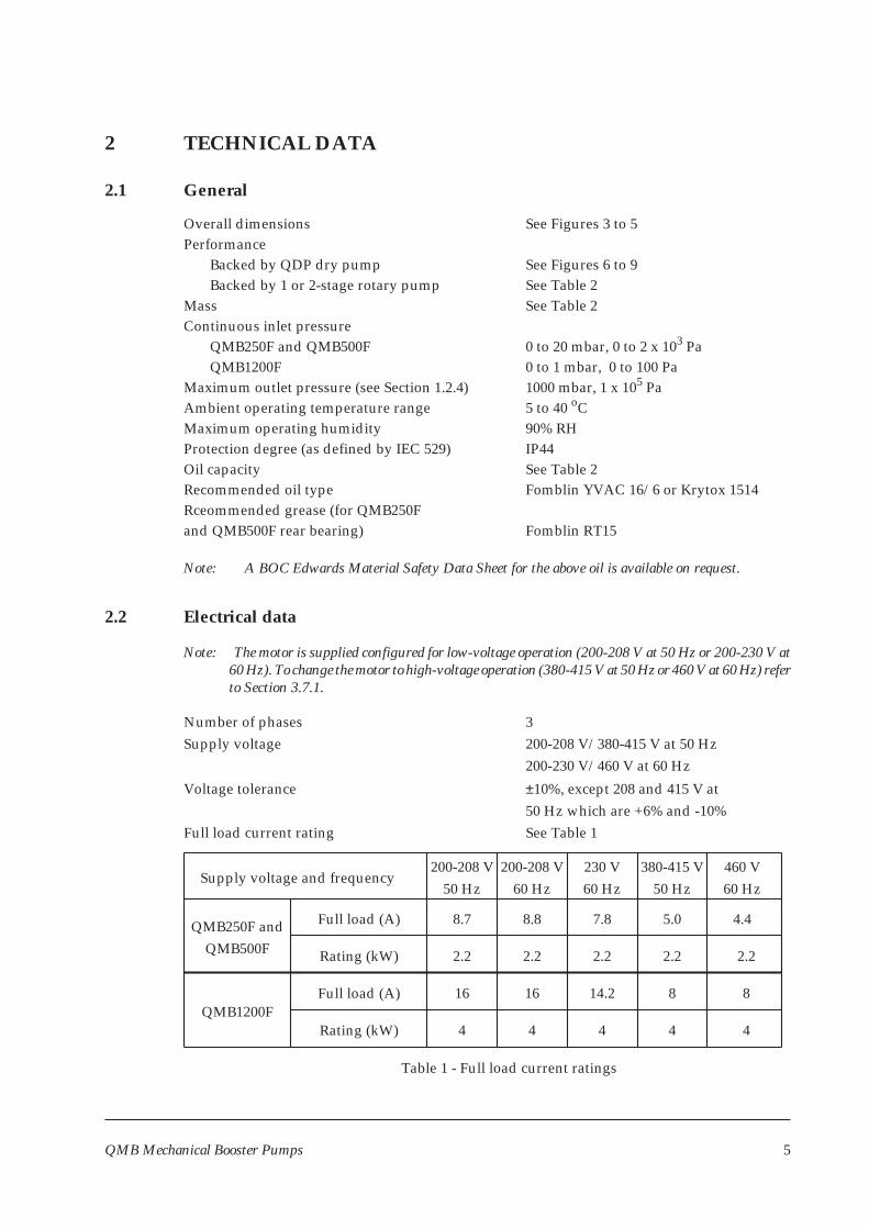
Overall dimensions See Figures 3 to 5Performance
Backed by QDP dry pump See Figures 6 to 9Backed by 1 or 2-stage rotary pump See Table 2
Mass See Table 2Continuous inlet pressure
QMB250F and QMB500F 0 to 20 mbar, 0 to 2 x 10³ PaQMB1200F 0 to 1 mbar, 0 to 100 Pa
Maximum outlet pressure (see Section 1.2.4) 1000 mbar, 1 x 10⁵ PaAmbient operating temperature range 5 to 40 oCMaximum operating humidity 90% RHProtection degree (as defined by IEC 529) IP44Oil capacity See Table 2Recommended oil type Fomblin YVAC 16/6 or Krytox 1514Rceommended grease (for QMB250Fand QMB500F rear bearing) Fomblin RT15
Note: A BOC Edwards Material Safety Data Sheet for the above oil is available on request.
2.2 Electrical data
Note: The motor is supplied configured for low-voltage operation (200-208 V at 50 Hz or 200-230 V at60 Hz). To change the motor to high-voltage operation (380-415 V at 50 Hz or 460 V at 60 Hz) referto Section 3.7.1.
Number of phases 3Supply voltage 200-208 V/380-415 V at 50 Hz
200-230 V/460 V at 60 Hz
Voltage tolerance ±10%, except 208 and 415 V at50 Hz which are +6% and -10%
Full load current rating See Table 1
QMB Mechanical Booster Pumps 5
2.2Rating (kW) 2.2 2.2
460 V60 Hz
380-415 V50 Hz
230 V60 Hz
200-208 V60 Hz
200-208 V50 Hz
Full load (A)
Supply voltage and frequency
8.7 8.8 7.8 5.0 4.4
2.2 2.2
Full load (A)
Rating (kW)
QMB250F andQMB500F
QMB1200F16 16 14.2 8 8
4 44 4 4
Table 1 - Full load current ratings
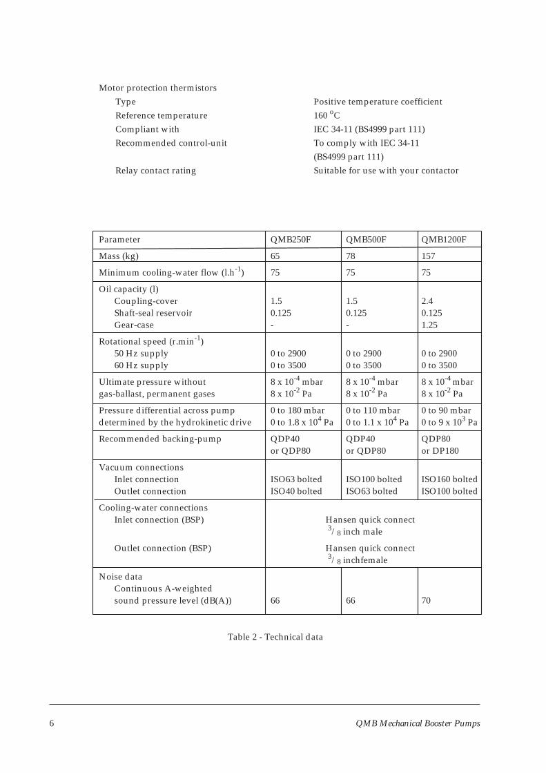
Motor protection thermistorsType Positive temperature coefficientReference temperature 160 oCCompliant with IEC 34-11 (BS4999 part 111)Recommended control-unit To comply with IEC 34-11
(BS4999 part 111)Relay contact rating Suitable for use with your contactor
Parameter QMB250F QMB500F QMB1200F
Mass (kg) 65 78 157
Minimum cooling-water flow (l.h-1) 75 75 75
Oil capacity (l)Coupling-cover 1.5 1.5 2.4Shaft-seal reservoir 0.125 0.125 0.125Gear-case - - 1.25
Rotational speed (r.min-1)50 Hz supply 0 to 2900 0 to 2900 0 to 290060 Hz supply 0 to 3500 0 to 3500 0 to 3500
Ultimate pressure without 8 x 10⁻⁴ mbar 8 x 10⁻⁴ mbar 8 x 10⁻⁴ mbargas-ballast, permanent gases 8 x 10⁻² Pa 8 x 10⁻² Pa 8 x 10⁻² Pa
Pressure differential across pump 0 to 180 mbar 0 to 110 mbar 0 to 90 mbardetermined by the hydrokinetic drive 0 to 1.8 x 10⁴ Pa 0 to 1.1 x 10⁴ Pa 0 to 9 x 10³ Pa
Recommended backing-pump QDP40 QDP40 QDP80or QDP80 or QDP80 or DP180
Vacuum connectionsInlet connection ISO63 bolted ISO100 bolted ISO160 boltedOutlet connection ISO40 bolted ISO63 bolted ISO100 bolted
Cooling-water connectionsInlet connection (BSP) Hansen quick connect
3/8 inch male
Outlet connection (BSP) Hansen quick connect3/8 inchfemale
Noise dataContinuous A-weightedsound pressure level (dB(A)) 66 66 70
Table 2 - Technical data
6 QMB Mechanical Booster Pumps
QMB Mechanical Booster Pumps 7
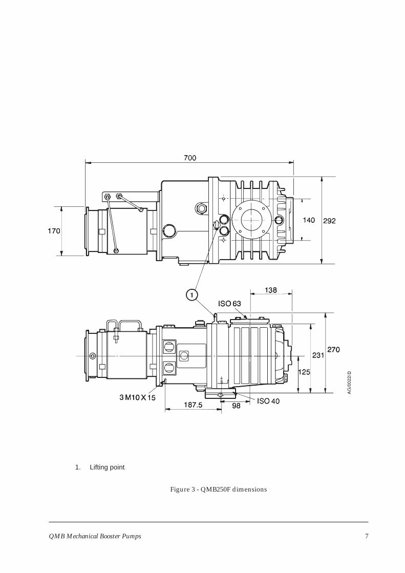
1. Lifting point
Figure 3 - QMB250F dimensions
8 QMB Mechanical Booster Pumps
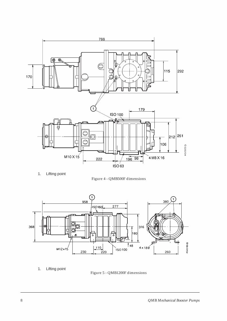
Figure 4 - QMB500F dimensions
Figure 5 - QMB1200F dimensions1. Lifting point
1. Lifting point
QMB Mechanical Booster Pumps 9
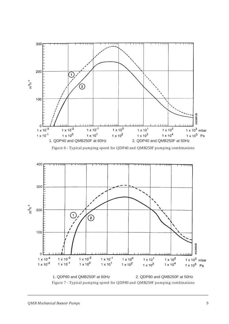
Figure 6 - Typical pumping speed for QDP40 and QMB250F pumping combinations
Figure 7 - Typical pumping speed for QDP80 and QMB250F pumping combinations1. QDP80 and QMB250F at 60Hz 2. QDP80 and QMB250F at 50Hz
1. QDP40 and QMB250F at 60Hz 2. QDP40 and QMB250F at 50Hz
10 QMB Mechanical Booster Pumps
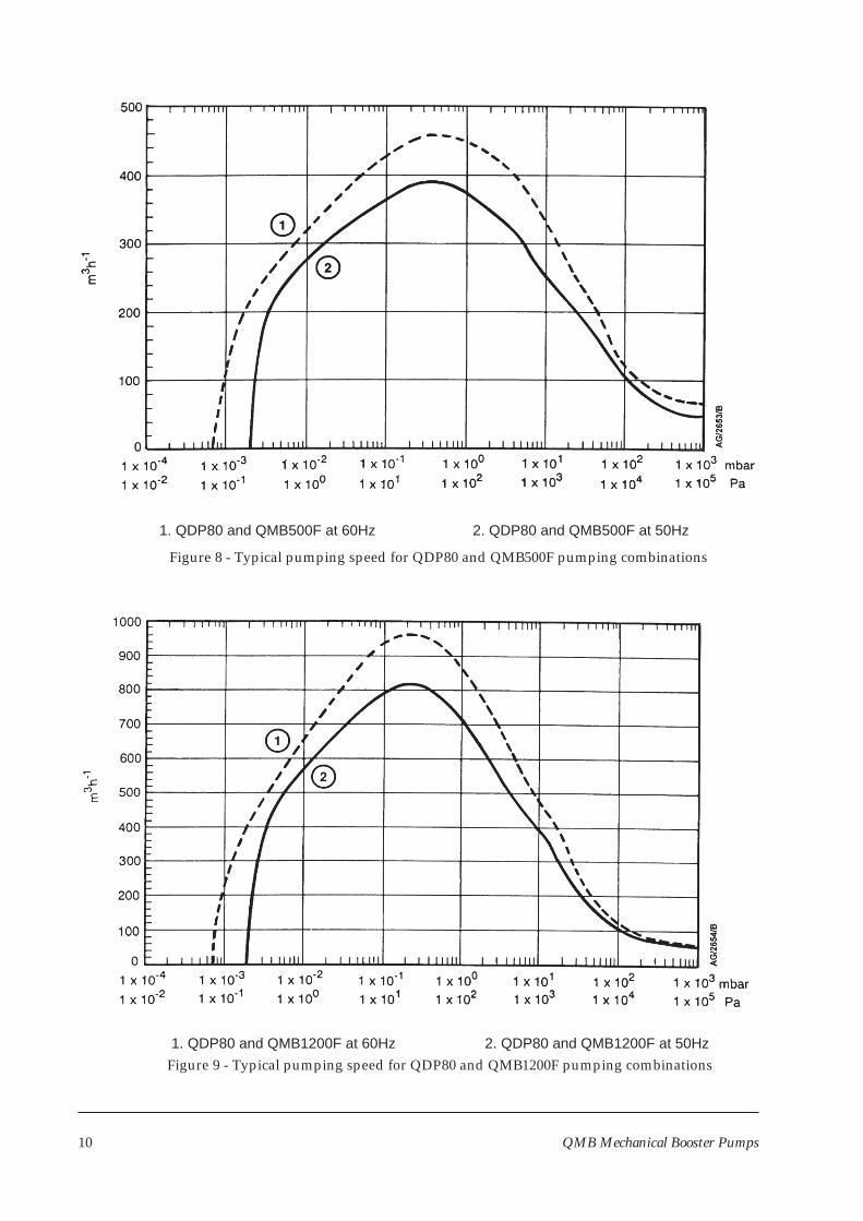
Figure 8 - Typical pumping speed for QDP80 and QMB500F pumping combinations
Figure 9 - Typical pumping speed for QDP80 and QMB1200F pumping combinations1. QDP80 and QMB1200F at 60Hz 2. QDP80 and QMB1200F at 50Hz
1. QDP80 and QMB500F at 60Hz 2. QDP80 and QMB500F at 50Hz
3 INSTALLATION
3.1 Safety
WARNING
Obey the safety instructions given below and take note of appropriate precautions. If youdo not, you can cause injury to people and damage to equipment.
• A suitably trained and supervised technician must install the pump.
• Ensure that the installation technician is familiar with the safety procedures which relate tothe products handled by the pumping system. Wear the appropriate safety-clothing whenyou come into contact with contaminated components. Dismantle and clean contaminatedcomponents inside a fume-cupboard.
• If the QMB pump is to replace an existing pump, vent and purge the process system withnitrogen for 15 minutes before you start installation work.
• Check that all the required components are available and of the correct type before you startwork.
• Disconnect the other components in the pumping system from the electrical supply so thatthey cannot be operated accidentally.
• Do not reuse any 'O' ring or 'O' ring assembly, and do not allow debris to get into the QMBpump during installation.
• Leak-test the system after installation work is complete to prevent leakage of hazardoussubstances out of the system and leakage of air into the system. Seal any leaks found toprevent leakage of dangerous substances out of the system, and leakage of air into thesystem.
• Do not remove the temporary cover or the blanking-plate from the QMB pump-inlet andpump-outlet until you are ready to connect the QMB pump to your vacuum system. Do notoperate the QMB pump unless the inlet blanking-plate is fitted, or the QMB pump isconnected to your vacuum system.
• Do not operate the QMB pump without a suitable backing pump: refer to Section 2.
• Wipe up any water or oil spilt during installation, so that people cannot slip over anyspillages.
• Safely route and secure cables, hoses and pipes during installation, so that people cannot tripover them.
• Obey all local and national rules and safety regulations when you install the QMB pump.
• Consult BOC Edwards publication P300-20-000 (Vacuum Pump and Vacuum SystemSafety) before you pump hazardous materials. This publication is available on request:contact your supplier or BOC Edwards.
QMB Mechanical Booster Pumps 11
3.2 Unpack and inspect
WARNING
Use suitable lifting equipment to move the pump. Refer to Section 2 for the mass of thepump.
1. Place the pallet in a convenient position with a fork-lift truck or a pallet truck.
2. Remove all packing materials.
3. Use suitable lifting-gear to remove the pump from its pallet. Do not try to lift the pump byhand. Refer to Section 2 for the mass of the pump.
4. Remove all protective covers and inspect the pump. If the pump is damaged, notify yoursupplier and the carrier in writing within three days; state the Item Number of the pumptogether with your order number and your supplier’s invoice number. Retain all packingmaterials for inspection. Do not use the pump if it is damaged.
5. If the pump is not to be used immediately, replace the protective covers. Store the pump insuitable conditions as described in Section 6.1.
3.3 Locate the pump
WARNING
Use suitable lifting equipment to move the pump. Refer to Section 2 for the mass of thepump.
Attach suitable lifting equipment to the lifting points on the pump (see Figures 3 to 5) to move thepump into its operating position. The pump must be mounted on a firm, level surface.
3.4 Fill the pump with oil
CAUTION
Ensure that the oil-levels in the pump are correct. If an oil-level is incorrect, pumpperformance may be affected and the pump may be damaged.
3.4.1 Coupling-cover
We recommend that the coupling-cover oil-level is maintained at the recommended oil-levelshown in Figure 10, item 5; if the oil-level is above or below the recommended oil-level, theperformance of the pump may be affected. Do not allow the coupling-cover oil-level to fallbelow the bottom of the reflector plate (Figure 10, item 4) or the pump may be damaged.
12 QMB Mechanical Booster Pumps
1. Remove the coupling-cover oil filler-plug (Figure 1, item 4).
2. Refer to Figure 10. Fill the coupling-cover with PFPE oil until the oil-level reaches therecommended oil-level (5) at the top of the reflector plate (4) in the coupling-coversight-glass (3).
3. Refit the coupling-cover oil filler-plug.
3.4.2 Shaft-seal reservoir
WARNING
Ensure that the correct vented filler-plug is replaced in the shaft-seal reservoir. If you use anon-vented plug, the reservoir will be pressurised and the oil sight-glass may fracture.
We recommend that you fill the shaft-seal reservoir so that the oil-level is at the recommendedoil-level, shown in Figure 10, item 2. You can operate the pump as long as the oil-level is abovethe bottom of the reflector plate. Do not allow the shaft-seal oil-level to fall below the bottom ofthe reflector plate or the pump may be damaged. You must use the same oil you used to fill thecoupling-cover.
QMB Mechanical Booster Pumps 13
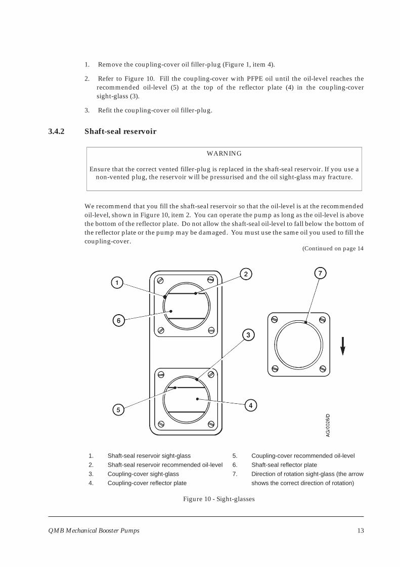
Figure 10 - Sight-glasses
1. Shaft-seal reservoir sight-glass
2. Shaft-seal reservoir recommended oil-level
3. Coupling-cover sight-glass
4. Coupling-cover reflector plate
5. Coupling-cover recommended oil-level
6. Shaft-seal reflector plate
7. Direction of rotation sight-glass (the arrow
shows the correct direction of rotation)
(Continued on page 14
1. Remove the shaft-seal reservoir vented oil filler-plug (Figure 1, item 3).
2. Refer to Figure 10. Fill the shaft-seal reservoir with PFPE oil until the oil-level is at therecommended oil-level (2) at the top of the reflector plate (6).
3. Refit the vented oil filler-plug.
3.4.3 Gear-cover (QMB1200F only)
Use the following procedure to fill the gear-cover on the QMB1200F pump. You must fill thegear-cover with the same oil you used to fill the coupling-cover and shaft-seal reservoir.
1. Refer to Figure 1. Remove the oil filler-plug (16) on the top of the gear-cover; take care not toaccidentally remove the plug from the external evacuation port (7).
2. Fill the gear-cover with oil until the oil-level is at the middle of the reflector plate in thegear-cover oil-level sight-glass (18).
3. Refit the oil filler-plug.
3.5 Cooling-water connections
WARNING
Do not turn on the cooling-water supply before you have finished all electrical installation.If you do, condensation may form inside the motor terminal-box and there may be a risk of
electric shock.
Connect the cooling-water supply and return pipelines to the quick connectors on thecooling-water brackets on the pump (see Figure 1).
Refer to Section 2 for the minimum cooling-water flow rate required. Do not turn on thecooling-water supply yet.
3.6 Connect to your emergency stop system
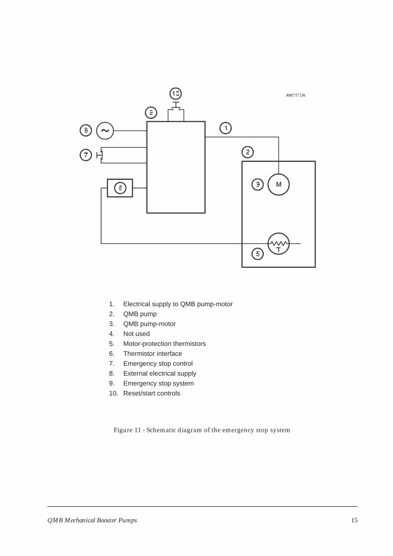
The QMB pump must be connected to an emergency stop facility. The operation of theemergency stop function should immediately disconnect power from the QMB pump when theemergency stop control is operated. Returning the emergency stop control to its normal positionshould not result in power being re-applied to the QMB pump; a separate start or reset controlshould be used for this.
The excess temperature detected by the motor protection thermistors should also be connectedto an emergency stop facility to cause the QMB pump to stop immediately, in the same way as theemergency stop function.
Refer to Figure 11 and to Section 3.7 for more information about the electrical connections.
14 QMB Mechanical Booster Pumps
QMB Mechanical Booster Pumps 15
Figure 11 - Schematic diagram of the emergency stop system
1. Electrical supply to QMB pump-motor
2. QMB pump
3. QMB pump-motor
4. Not used
5. Motor-protection thermistors
6. Thermistor interface
7. Emergency stop control
8. External electrical supply
9. Emergency stop system
10. Reset/start controls
3.7 Electrical connections
WARNING
Use suitable cable-glands so that the seals of the electrical supply and thermistor cableentries into the motor terminal-box meet the requirements of IP44 (or higher), as definedby IEC 529. If you do not, condensation may form inside the terminal-box and there may
be a risk of electric shock.
3.7.1 High and low-voltage operation
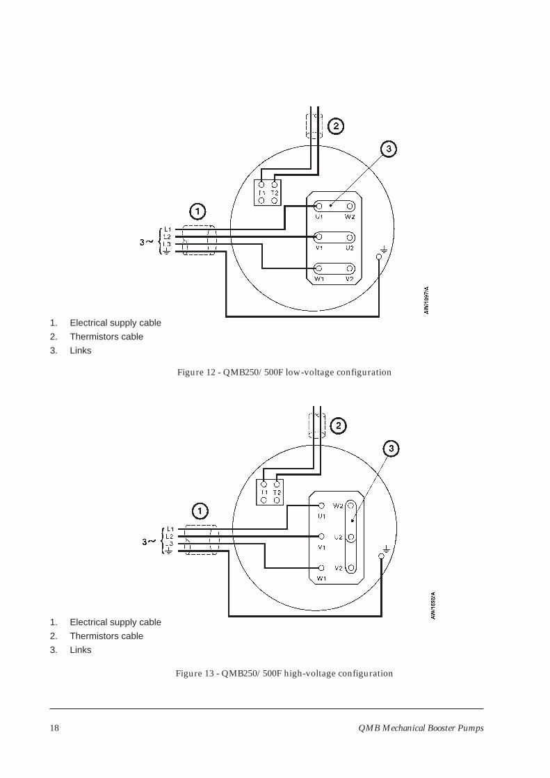
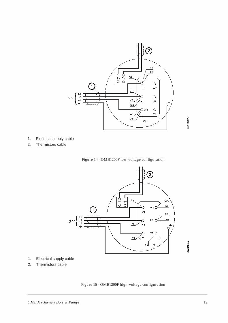
The universal motors are supplied configured for ‘low-voltage’ operation (200-208 V at 50 Hz or200-230 V at 60 Hz). Figures 12 and 14 show the low voltage configurations for theQMB250/500F and QMB1200F pumps.
To change the QMB250/500F pump-motor to ‘high-voltage’ operation (380-415 V at 50 Hz or 460V at 60 Hz), remove the pump-motor terminal-box cover, then remove the three links from the U,V and W terminals. Link the U1, V1 and W1 terminals as shown in Figure 13.
To change the QMB1200F pump-motor to ‘high-voltage’ operation (380-415 V at 50 Hz or 460 V at60 Hz), remove the pump-motor terminal-box cover, then remove the wires from the U1, V1 andW1 terminals. Reconnect the wires to the terminals as shown in Figure 15.
3.7.2 Motor connections
CAUTION
The motor must be correctly configured and you must make the correct electricalconnections for your electrical supply. If you do not, you can damage the motor.
Connect the motor to the electrical supply as described below. Connect the supply through acontactor which has overload-protection, or use a controller which incorporates a contactor. Youmust use a contactor which has a manual reset control. If you do not, the pump couldautomatically restart after an electrical overload or an electrical supply failure.
1. Remove the motor terminal-box cover.
2. Check your electrical supply voltage and frequency. If necessary, configure the motor tooperate with your supply voltage (see Section 3.7.1).
3. Remove the plug from the cable entry-hole you will use for the electrical supply cable.Choose the most suitable entry-hole for your application.
4. Fit a suitable 20 mm cable-gland to the hole. If your cable is too large to pass through a 20 mmcable-gland, fit a 20 mm to 25 mm female thread-adaptor to the cable entry-hole, and fit a25 mm cable-gland to the adaptor. The cable-gland (and adaptor, if fitted) must provide aprotective seal to IP44 (or higher), as defined by IEC 529.
16 QMB Mechanical Booster Pumps
5. Pass the supply cable through the cable-gland and connect the wires of the electrical supplycable to the appropriate terminals (see Figures 12 to 15).
6. Tighten the cable-gland.
3.7.3 Motor-protection thermistors
Connect the output of the motor-protection thermistors to your control equipment to switch offthe pump if the motor is too hot. Refer to Section 2 for the specification of a suitable control-unit.To connect the thermistors output:
1. Remove the plug from the other cable entry-hole.
2. Fit a suitable 20 mm cable-gland to the entry-hole. The cable-gland must be a protective sealto IP44 (or higher) as defined by IEC 529.
3. Pass the thermistor cable through the cable-gland.
4. Refer to Figures 12 to 15. Connect the two wires of the thermistor cable to the thermistorterminals (T1 and T2). Connect the other ends of the wires to your control equipment.
5. Tighten the cable-gland, then refit the motor terminal-box cover.
3.8 Check the pump rotation
WARNING
Blank the inlet or connect the pump to the vacuum system before you check the directionof pump rotation. If you do not, there is danger of objects being trapped in the rotating
rotors.
It is possible for the three-phase electrical supply to the motor to be phased incorrectly. If thesupply is phased incorrectly, the rotors will rotate slowly in the reverse direction or remainstationary. Look through the direction of rotation sight-glass in the coupling-cover (Figure 1,item 11) to check the direction of rotation of the motor-coupling. An enlarged view of thesight-glass is shown in Figure 10. The correct direction of rotation is indicated by an arrow.Check the direction of rotation as described below.
1. Check that the pump is connected to the vacuum system or that the inlet is blanked off.
2. Connect the backing-pump and switch the backing-pump on.
3. Watch the motor-coupling in the sight-glass (Figure 10, item 7) and switch on the QMBpump for two or three seconds.
4. Check that the direction of rotation of the coupling is the same as that indicated by therotation arrow on the motor and shown in Figure 10.
5. If the direction of rotation of the coupling is incorrect, switch off the backing-pump andisolate the QMB pump from the electrical supply. Reverse any two of the phase-wires in themotor terminal-box.
6. Repeat the check to ensure that the direction of rotation is now correct.
QMB Mechanical Booster Pumps 17
18 QMB Mechanical Booster Pumps
Figure 12 - QMB250/500F low-voltage configuration
Figure 13 - QMB250/500F high-voltage configuration
1. Electrical supply cable
2. Thermistors cable
3. Links
1. Electrical supply cable
2. Thermistors cable
3. Links
QMB Mechanical Booster Pumps 19
Figure 14 - QMB1200F low-voltage configuration
Figure 15 - QMB1200F high-voltage configuration
1. Electrical supply cable
2. Thermistors cable
1. Electrical supply cable
2. Thermistors cable
3.9 Connect the pump-inlet and outlet
Consider the following points when you connect your pump:
• You must use a suitable backing pump: refer to Section 2.
• For optimum pumping speeds, ensure that the pipeline connected to the pump-inlet is asshort as possible and has a bore size not less than the inlet-port diameter.
• On very dusty applications, use a low-impedance inlet-filter to minimise abrasion in thepump. A range of inlet-filters is available; if necessary, contact your supplier or BOCEdwards for advice.
• Adequately support vacuum pipelines to stop the transmission of stress to the pipelinejoints.
• If necessary, incorporate flexible pipelines in your system pipelines to reduce thetransmission of vibration and to prevent loading of coupling-joints. If you use flexiblepipelines, you must ensure that you use flexible pipelines which have a maximum pressurerating which is greater than the highest pressure that can be generated in your system.
• You must be able to isolate the pump-inlet and exhaust from the atmosphere and from yourvacuum system if you have used corrosive chemicals in the pump.
• You can incorporate a suitable control system so that the QMB pump is only switched on ifthe inlet pressure is below the maximum inlet pressure.
Before you connect the QMB pump to your vacuum system, remove the blanking-plates fitted tothe pump-inlet and outlet. Retain the nuts, bolts and washers for future use. Retain theblanking-plates for future use as temporary covers, for uncontaminated pumps only.
Ensure that debris does not get into the pump when you install it. If the pump is to replace apump in an existing system, purge the existing pump with nitrogen for 15 minutes before youdisconnect it.
Use standard ISO flanges to connect the pump-inlet and outlet. Use a BOC Edwards trapped ‘O’ring to seal the pump-inlet connection and use a BOC Edwards trapped ‘O’ ring or (on theQMB250F only) a BOC Edwards Co-Seal to seal the pump-outlet connection.
3.10 External evacuation of coupling-cover (optional)
You can use an external pump to evacuate the coupling-cover. A description of the connectionsrequired is beyond the scope of this manual. Contact your supplier or your nearest BOCEdwards company for advice if you wish to use this facility.
20 QMB Mechanical Booster Pumps
4 OPERATION
4.1 Operational safety
WARNING
Do not touch any part of the pump when it is switched on. Surfaces of the pump are veryhot, especially at high inlet pressures, and can cause injury to people and damage to
equipment.
If you operate the QMB250F or QMB500F pump in an area with poor ventilation, thetemperature of the coupling-cover can reach 100 oC and above. Take all necessary precautions toavoid accidental contact with the coupling-cover; if necessary, use a pump enclosure or fit aguard to the pump.
If you operate the QMB1200F pump with the inlet pressure higher than 1 mbar (100 Pa) for a longperiod, the stator and the coupling-cover will reach very high temperatures. Take all necessaryprecautions to avoid accidental contact with the stator and the coupling-cover; if necessary, use apump enclosure or fit a guard to the pump.
4.2 Start-up
Start-up the pump as described in the procedure below. This procedure assumes that the pumpand the vacuum system are at atmospheric pressure.
1. Check that the pump oil-levels are correct (see Section 3.4).
2. Switch on the cooling-water supply and check that there is an adequate flow of cooling-water.
3. Close all valves to atmospheric pressure and ensure that all other openings are closed.
4. Switch on the backing pump and open the backing valve (if fitted).
5. When the inlet pressure is below the maximum inlet pressure for the pump, switch on thepump.
6. Slowly open the pump-inlet isolation-valve (if fitted).
7. Allow the pump to operate for approximately fifteen minutes to achieve normal operatingtemperature.
8. Inspect the cooling-water connections and pipes and check that there are no leaks. If thereare any leaks, shut down the pumping system (refer to Section 4.3) and seal the leaks.
QMB Mechanical Booster Pumps 21
4.3 Shut-down
1. Close the pump-inlet isolation-valve (if fitted).
2. Switch off the mechanical booster pump.
3. Open the backing-pump air-admittance valve (if fitted) and switch off the backing-pump.
4. Turn off the cooling-water supply.
22 QMB Mechanical Booster Pumps
5 MAINTENANCE
5.1 Safety
WARNING
Obey the safety instructions given below and take note of appropriate precautions. If youdo not, you can cause injury to people and damage to equipment.
• A suitably trained and supervised technician must maintain the pump.
• Ensure that the maintenance technician is familiar with the safety procedures which relate tothe products pumped. Wear the appropriate safety-clothing when you come into contactwith contaminated components. Dismantle and clean contaminated components inside afume-cupboard.
• Allow the pump to cool to a safe temperature before you start maintenance work
• Vent and purge the pumping system with nitrogen before you start any maintenance work.
• Check that all the required parts are available and of the correct type before you start work.
• Isolate the pump and other components from the electrical supply so that they cannot beoperated accidentally.
• Recheck the pump rotation direction if the electrical supply has been disconnected.
• Do not reuse any 'O' ring or 'O' ring assembly, and do not allow debris to get into the QMBpump during maintenance.
• Dispose of components safely (see Section 6.2).
• Take care to protect sealing-faces from damage.
• Do not touch or inhale the thermal breakdown products of fluorinated materials which maybe present if the pump has been overheated to 260 oC and above. These breakdown productsare very dangerous. Fluorinated materials in the pump may include oils, greases and seals.The pump may have overheated if it was misused, if it malfunctioned or if it was in a fire.BOC Edwards Material Safety Data Sheets for fluorinated materials used in the pump areavailable on request: contact your supplier or BOC Edwards.
• Leak-test the system after maintenance work is complete if you have connected ordisconnected any vacuum joints. Seal any leaks found to prevent leakage of dangeroussubstances out of the system, and leakage of air into the system.
• Fit suitable blanking-plates to the pump-inlet and outlet as soon as you have disconnectedthe QMB pump from your vacuum system. Do not operate the pump unless the inletblanking-plate is fitted, or the pump is connected to your vacuum system.
• Do not operate the QMB pump without a suitable backing pump: refer to Section 2.
• Wipe up any water or oil spilt during maintenance, so that people cannot slip over anyspillages.
• Safely route and secure all cables, hoses and pipes during maintenance, so that peoplecannot trip over them.
QMB Mechanical Booster Pumps 23
5.2 Maintenance plan
The plan shown in Table 3 details the maintenance operations necessary to maintain QMBpumps in normal use. Instructions for each operation are given in the section shown.
More frequent maintenance may be required if the pump has been used to pump corrosive orabrasive gases and vapours. If necessary, adjust the maintenance plan according to yourexperience.
Operation Frequency Refer to Section
Check the oil-levels 3 monthly 5.3
Inspect the pump connections Monthly 5.4
Lubricate the rear-bearing * 12 monthly 5.5
Change the pump oil As required 5.6
* QMB250F and QMB500F onlyTable 3 - Maintenance plan
5.3 Check the oil-levels
CAUTION
Ensure that the oil-levels in the pump are correct. If an oil-level is incorrect, pumpperformance may be affected and the pump may be damaged.
Note: If there is a loss of oil from the shaft-seal reservoir, the shaft-seal may have failed. You cannot
replace the shaft-seal ; contact your supplier or a BOC Edwards Service Centre for advice.
Use the following procedure to check the oil-levels in the sight-glasses. Refer to Figure 1 for thelocation of the filler-plugs and sight-glasses. During normal operation, the coupling-coversight-glass (Figure 10, item 2) may appear empty or show a froth because the oil is in circulationaround the coupling.
1. Refer to Figure 10. Check the shaft-seal oil-level. If the oil-level is below the bottom of thereflector plate (6), refer to Section 3.4 and refill the shaft-seal reservoir.
2. Check the coupling-cover oil-level. If the oil-level is below the top of the reflector plate, referto Section 3.4 and refill the coupling-cover reservoir.
3. On the QMB1200F only, check the gear-cover oil-level in the gear-cover sight-glass (Figure 1,item 18). If the oil-level is below the middle of the reflector plate, refer to Section 3.4 and refillthe gear-cover.
24 QMB Mechanical Booster Pumps
5.4 Inspect the pump connections
1. Check that the cooling-water connections are secure. Tighten any connections that are loose.
2. Inspect the cooling-water pipelines and connections and check that they are not corroded ordamaged and do not leak. Replace any pipelines and connections which are corroded ordamaged or leak.
3. Check that the electrical connections are secure. Tighten any connections that are loose.
4. Check the electrical supply cables for damage. Replace any cable which is damaged.
5. Check that all the vacuum connections are secure. Tighten any connections that are loose.
6. Inspect all the vacuum pipelines and connections and check that they are not corroded ordamaged. Replace any pipelines and connections which are corroded or damaged.
5.5 Lubricate the rear-bearing (QMB250F and QMB500F only)
1. Switch off the pump and isolate it from the electrical supply. Vent the pump to atmosphericpressure.
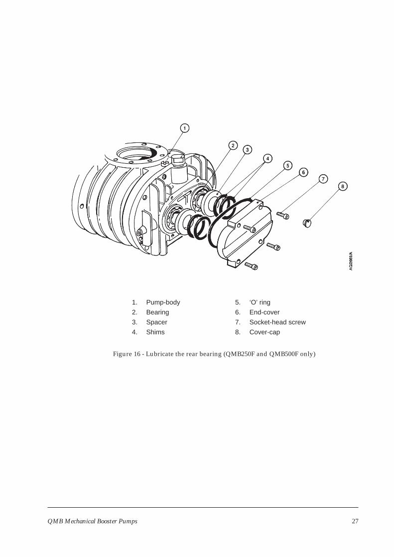
2. Refer to Figure 16. Remove the four plastic cover-caps (8) from the end-cover (6).
3. Undo and remove the socket-head screws (7) located under the four plastic cover-caps.
4. Remove the end-cover (6) and ‘O’ ring (5). Dispose of the ‘O’ ring safely.
5. Note the exact location of the shims (4) and spacers (3) inside the end-cover (6). Clean off allvisible grease from the end-cover; take care not to misplace or damage the shims andspacers.
6. Use a clean, lint-free cloth or a plastic or wooden spatula to remove all visible grease fromboth bearings (2).
7. Fill the visible side of each bearing (2) with clean grease, then lightly force the grease into thebearings.
8. Apply a light wipe of high-vacuum grease to the new ‘O’ ring (5) and fit it into the groove inthe end-cover (6).
9. Check that the shims (4) and spacers (3) are correctly located in the end-cover (6).
10. Fit the end-cover (6) and secure with the four socket-head screws (7). Tighten the screwsevenly and refit the plastic cover-caps (8).
QMB Mechanical Booster Pumps 25
5.6 Change the pump oil
WARNING
Ensure that the correct vented filler-plug is replaced in the shaft-seal reservoir. If you use anon-vented plug, the reservoir will be pressurised and the oil sight glass may fracture.
CAUTION
Ensure that the oil-levels in the pump are correct. If an oil-level is incorrect, pumpperformance may be affected and the pump may be damaged.
Replace the pump oil as described below. Refer to Figure 1 for the location of the oil-filler anddrain-plugs.
1. Switch off the pump and allow it to cool.
2. Remove the coupling-cover oil filler-plug (4).
3. Remove the coupling-cover oil drain-plug (10) from the underside of the coupling-cover andallow the oil to drain into a suitable container.
4. Remove the shaft-seal vented oil filler-plug (3). Use a suitable pump to suck the oil out of theshaft-seal reservoir.
5. Refit the coupling-cover oil drain-plug (10).
6. Refer to Section 3.4 and fill the coupling-cover and shaft-seal reservoir with oil.
7. Refit the coupling-cover oil filler-plug (4) and the shaft-seal vented oil filler-plug (3).
8. On QMB1200F pumps only:
• Remove the filler-plug on the gear-cover; take care not to accidentally remove the plugfrom the external evacuation port (7).
• Remove the drain-plug from the underside of the gear-cover and allow the oil to draininto a suitable container.
• Refit the drain-plug and refer to Section 3.4 to refill the gear-cover with oil.
26 QMB Mechanical Booster Pumps
QMB Mechanical Booster Pumps 27
Figure 16 - Lubricate the rear bearing (QMB250F and QMB500F only)
1. Pump-body
2. Bearing
3. Spacer
4. Shims
5. ‘O’ ring
6. End-cover
7. Socket-head screw
8. Cover-cap
6 STORAGE AND DISPOSAL
6.1 Storage
Use the procedure below to store the pump.
1. Shut-down the pump as described in Section 4.
2. Isolate the pump from the electrical supply and disconnect it from the vacuum system.
3. Clean the pump and change the oil as described in Section 5.
4. Place protective covers over the inlet and outlet-flanges.
5. Store the pump in cool, dry conditions until required for use. When required, prepare andinstall the pump as described in Section 3.
6.2 Disposal
Dispose of the pump and any components safely in accordance with all local and national safetyand environmental requirements.
Take particular care with components which have been contaminated with dangerous processsubstances.
28 QMB Mechanical Booster Pumps
7 SERVICE, SPARES AND ACCESSORIES
7.1 Introduction
BOC Edwards products, spares and accessories are available from BOC Edwards companies inBelgium, Brazil, China, France, Germany, Israel, Italy, Japan, Korea, Singapore, UnitedKingdom, U.S.A and a world-wide network of distributors. The majority of these centres employService Engineers who have undergone comprehensive BOC Edwards training courses.
Order spare parts and accessories from your nearest BOC Edwards company or distributor.When you order state for each part required:
• Model and Item Number of your equipment
• Serial number
• Item Number and description of part.
7.2 Service
BOC Edwards products are supported by a world-wide network of BOC Edwards ServiceCentres. Each Service Centre offers a wide range of options including: equipmentdecontamination; service exchange; repair; rebuild and testing to factory specifications.Equipment which has been serviced, repaired or rebuilt is returned with a full warranty.
Your local Service Centre can also provide BOC Edwards engineers to support on-sitemaintenance, service or repair of your equipment.
For more information about service options, contact your nearest Service Centre or other BOCEdwards company.
7.3 Spares
The spare parts listed below are available for the QMB Mechanical Booster Pump:
Product Item Number
RT15 Fomblin grease (100gm) H113-50-003End-cover ‘O’ ring (QMB250F and QMB500F) H021-22-091Gear-cover ‘O’ ring (QMB1200F) H021-22-159Fomblin YVAC 16/6 fluid (1kg) H113-06-019Fomblin YVAC 16/6 fluid (5kg) H113-06-020Krytox 1514 fluid (1kg) H113-08-018Krytox 1514 fluid (5kg) H113-08-020
QMB Mechanical Booster Pumps 29
7.4 Accessories
Note The accessories listed in Sections 7.4.2 and 7.4.3 are designed to be used together with the Booster
Frame described in Section 7.4.1.
7.4.1 QMB Booster Frames
The QMB Booster Frame supports the QMB pump and allows you to leave the QMB pumpinstalled in the vacuum system while you install or remove a QDP dry pump.
Product Item Number
QMB Booster Frame for QDP40/QMB250F A528-37-000QMB Booster Frame for QDP40/QMB500F, QDP80/QMB250F
and QDP80/QMB500F A528-38-000QMB Booster Frame for QDP80/QMB1200F A528-39-000
7.4.2 QMB Booster Frame Connection Kits
These kits enable a QMB pump fitted in a Booster Frame to be mounted onto a QDP dry pump.Each kit contains a sub-frame to support the QMB pump before you install the QDP pump, aflange adaptor (if necessary) and cooling-water pipes and connections to connect the QMBpump cooling-system to the QDP pump cooling-system.
Product Item Number
QMB Booster Frame Connection Kit for QDP40/QMB250F A528-65-000QMB Booster Frame Connection Kit for QDP40/QMB500F A528-66-000QMB Booster Frame Connection Kit for QDP80/QMB250F A528-67-000QMB Booster Frame Connection Kit for QDP80/QMB500F A528-68-000QMB Booster Frame Connection Kit for QDP80/QMB1200F A528-69-000
7.4.3 QMB Booster Frame Acoustic Enclosures
When fitted to a QMB Booster Frame, an Acoustic Enclosure reduces noise from the QMB andQDP pumps.
Product Item Number
QMB Booster Frame Acoustic Enclosure for QDP40/QMB250F A528-70-000QMB Booster Frame Acoustic Enclosure for QDP40/QMB500F A528-71-000QMB Booster Frame Acoustic Enclosure for QDP80/QMB250F A528-72-000QMB Booster Frame Acoustic Enclosure for QDP80/QMB500F A528-73-000QMB Booster Frame Acoustic Enclosure for QDP80/QMB1200F A528-74-000
30 QMB Mechanical Booster Pumps
7.4.4 QMB to QMKII Connection Kits
These kits enable a QMB pump to be mounted onto the QDP dry pump in a QMKII system.
Product Item Number
QMB250F to QMKII Connection Kit A529-33-000QMB500F to QMKII Connection Kit A529-34-000QMB1200F to QMKII Connection Kit A529-35-000
QMB Mechanical Booster Pumps 31

(This page deliberately left blank)
32 QMB Mechanical Booster Pumps