Embed Size (px)
Citation preview
Instruction and Descriptive List of Parts
The MERROW PLAIN CROCHET
8 L A N K E T H E M P~ I N G and E 0 G I N G and
SHELL STITCH MACHINES
THE MERROW MACHINE COMPANY 28 LAUREL STREET HARTFORD. CONNECTICUT 06106 U.S.A.
From the library of: Superior Sewing Machine & Supply LLC

INSTRUCTIONS
FOR SETTING UP AND OPERATING AND DESCRIPTIVE LIST OF PARTS FOR PLAIN
CROCHET BLANKET HEMMING AND EDGING AND SHELL STITCH MACHINES
This book contains instructions for setting up and operating Merrow High Speed Plain Crochet, Blanket Hemming, and Edging on Shell Stitch Machines, together with illustrations oft he representative parts and a descriptive list of the commonly used parts.
All moving parts subject to friction and wear have been carefully designed and accurately formed to give the maximum utility, durability, and interchangeability for continuous and perfect operation at high speed.
In addition to the machines described in this booklet, we also make Merrow Class MG and Class M Overstitching Machines and Class 70 Butted Seaming Machines. These machines have been long and favorably known and used by manufacturers throughout the world.
Over a period of years, numerous parts for our Machines have been designed for special uses and since their application is limited, these parts are not listed herein. It is anticipated that new parts will be developed in the future as style and fashion change. Your individual problems will receive our prompt attention.
HOW TO ORDER We keep a record of each part model contained in the various machines as
they leave our factory, and can supply duplicates if given theN AM Eofthe part with STYLE and SERIAL number of Machine.
If difficulty is experienced in selecting which of the many parts is the one needed, give the NAME of the part indicated in Descriptive List with STYLE and SERIAL number of Machine for which such part is desired, and we expect to be able to make proper selection.
When ordering Needle Plates and Needle Guards, state the size of Needle used.
Letters or numbers are stamped on most of the parts when ordering duplicates, give the NAME of part and the LETTERS or NUMBERS stamped thereon. The stamping on a particular part is insufficient information without giving the NAME of the part. The PART NUMBER is stamped on the shank near the butt end of all crochet hooks.
THE MERROW MACHINE COMPANY 28 LAUREL STREET. HARTFORD, CONNECTICUT, 06106 USA
Established 1838 Incorporated /894
From the library of: Superior Sewing Machine & Supply LLC
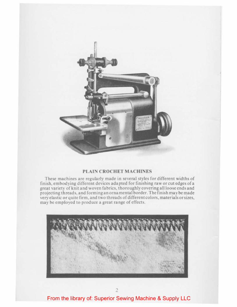
PLAIN CROCHET MACHINES
fhese machines are regularly made in several styles for different widths of fintsh. embodying different de\ ices adapted for finishmg raw or cut edges of a great vanet}' of knn and \voven fabrics, thoroughly covering all loose ends and projecting threads, and formingan ornamental border. The finish may be made very elastic or quite firm. and two threads of different colors, materials or sizes, may be employed to produce a great range of effech .
..,
From the library of: Superior Sewing Machine & Supply LLC
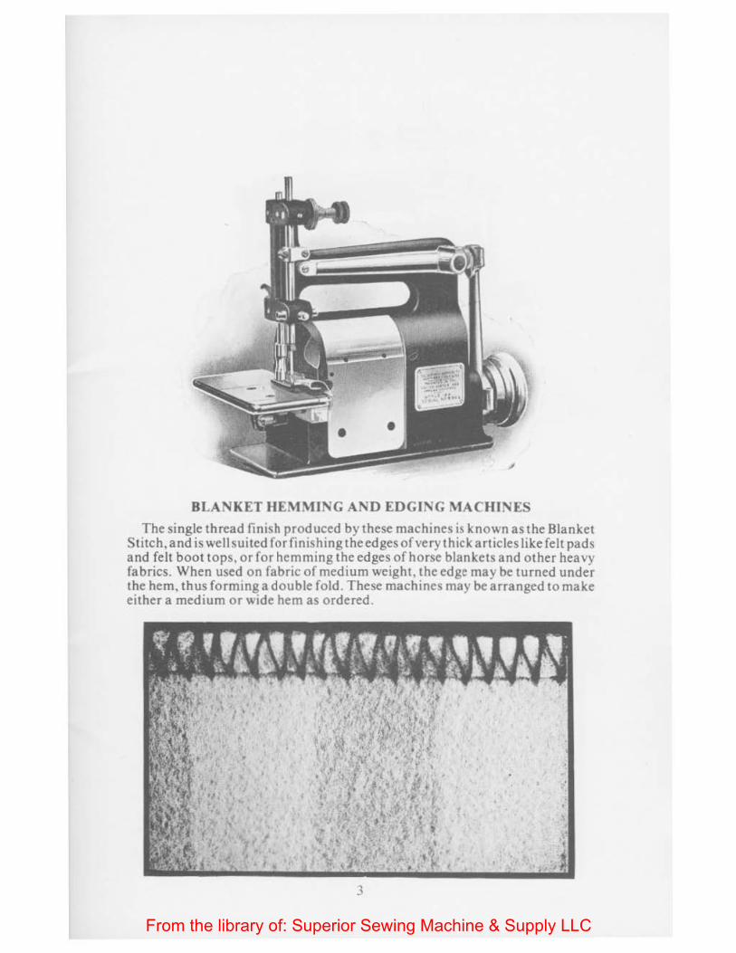
BLAN KET HEMMING AND EDGING MACHINES The single thread finish produced by these machines is known as the Blanket
Stitch, and is well suited for finishing the edges of very thick articles like felt pads and felt boot tops, or for hemming the edges of horse blankets and other heavy fabrics. When used on fabric of medium weight, the edge may be turned under the hem, thus forming a double fold. These machines may be arranged to make either a medium or wide hem as ordered.
3
From the library of: Superior Sewing Machine & Supply LLC

SHELL STITCH MACHINES
These machines produce our two thread crochet stitch in clusters, giving a shell-like effect, closely resembling hand work. The finish is extremely attractive and subtantial, and is suitable for ornamenting the edges of a great variety of articles of utility and apparel.
Quite a range in the size of the shells is obtainable in the different styles of machines, and by the use of a variety of colors and sizes of thread or yarn, the results are pleasing.
4
From the library of: Superior Sewing Machine & Supply LLC
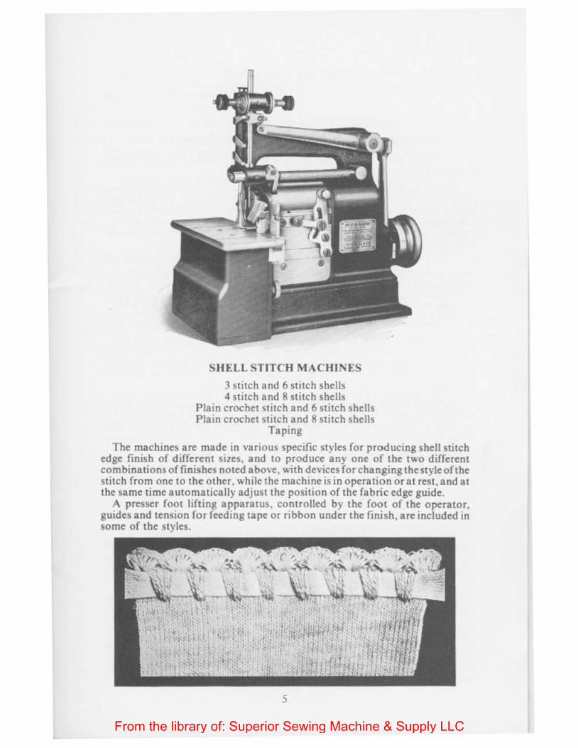
SHELL STITCH MACHINES
3 stitch and 6 stitch shells 4 stitch and 8 stitch shells
Plain crochet stitch and 6 stitch shells Plain crochet stitch and 8 stitch shells
Taping
The machines are made in various specific styles for producing shell stitch edge finish of different sizes, and to produce any one of the two different combinations of finishes noted above, with devices for changing the style of the stitch from one to the other, while the machine is in operation or at rest, and at the same time automatically adjust the position of the fabric edge guide.
A presser foot lifting apparatus, controlled by the foot of the operator, guides and tension for feeding tape or ribbon under the finish, are included tn some of the styles.
5
From the library of: Superior Sewing Machine & Supply LLC

INSTRUCTIONS
SETTING UP AND OPERATING PLAIN
CROCHET AND SHELL STITCH MACHINES
I. Provide a smooth table with a top at least two inches thick and about twenty-eight inches high.
2. Immediately after removing the machine from its box, observe the threading carefully, and compare it with the threading diagram shown on page 19. The manner of threading is notexactlythesame in all kinds of machines, and a diagram showing the threading is sent with each machine, but for general purposes, cuts included in this book may be referred to in connection with the printed description of the threading.
3. Secure the machine to the table with the felt pad sent with the machine under the base of the machine, using the screws also sent with the machine, the hand wheel being placed at the right hand oft be operator, and the front or base of the machine parallel with the front edge of the table, and with the center of the main shaft of the machine about five inches back from the front of the table.
4. A power transmitter should be used for starting and stopping the machine.
5. When laying out the transmission equipment, attempt should be made to avoid driving from a large pulley to a relatively smaller pulley, the centers of which are close together, as such an arrangement will allow excessive slippage of the belts, materially reducing the speed of the start and stop of the Merrow Machine.
6. A Hand Wheel with an effective (pitch) diameter of 3 7 ' 32" is supplied with each machine. If an individual transmttter tS used, the machine may be run with a 3/ 8" endless V-Belt. For group drive where round belting is used, either I 4" or 5 , 16" round belting may be used.
7. Avoid crossed belts where possible.
8. The top of the Hand Wheel of the Merrow Machine must turn away from the operator.
Speed to Run Machines
9. Style 18 Single Thread Blanket Hemming and Edging Machines should be run from 1000 to 1200 stitches per minute.
Styles 15 and 24 Two Thread Plain Crochet Machines should be run from 1200 to 1600 stitches per minute.
Style 17 Two Thread Plain Crochet Machines should be run from 1000 to 1500 stitches per minute.
Styles 22. 27. and 35 Shell Stitch Machines and modifications thereof should be run from 1200 to 1500 stitches per mtnute.
Lubrication
10. Keep the machine clean. Oil frequently, at least four times a day. These machines are necessarily fitted very closely in order to attain their high speed and great durability, and therefore they need frequent oiling, especially when new.
6
From the library of: Superior Sewing Machine & Supply LLC
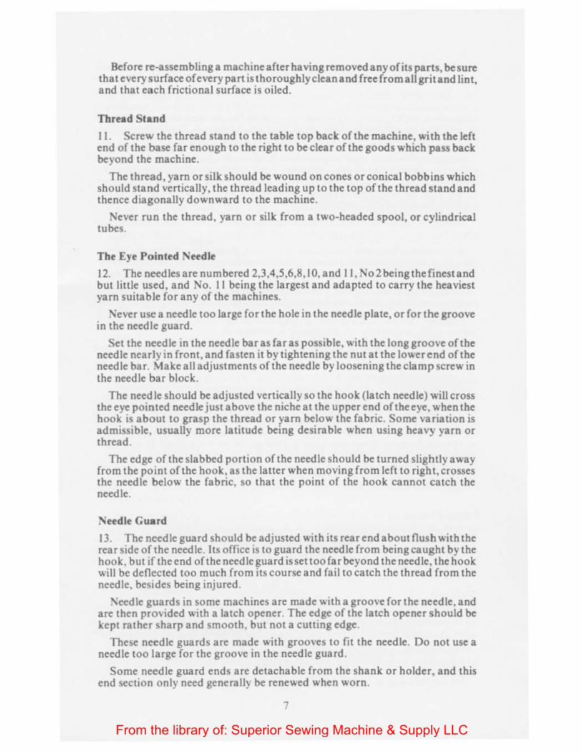
Before re~assembling a machine after having removed any of its parts, be sure that every surface of every part is thoroughly clean and freefromallgritand lint, and that each frictional surface is oiled.
Thread Stand
II. Screw the thread stand to the table top back of the machine, with the left end of the base far enough to the right to be clear of the goods which pass back beyond the machine.
The thread, yarn or silk should be wound on cones or conical bobbins which should stand vertically, the thread leading up to the top of the thread stand and thence diagonally downward to the machine.
Never run the thread, yarn or silk from a two-headed spool, or cylindrical tubes.
The Eye Pointed Needle
12. The needles are numbered 2,3,4,5,6,8,10, and II, No2beingthefinestand but little used, and No. II being the largest and adapted to carry the heaviest yarn suitable for any of the machines.
Never use a needle too large for the hole in the needle plate, or for the groove in the needle guard.
Set the needle in the needle bar as far as possible, with the long groove oft he needle nearly in front, and fasten it by tightening the nut at the lower end of the needle bar. Make all adjustments of the needle by loosening the clamp screw in the needle bar block.
The needle should be adjusted vertically so the hook (latch needle) will cross the eye pointed needle just above the niche at the upper end oftheeye, when the hook is about to grasp the thread or yam below the fabric. Some variation is admissible, usually more latitude being desirable when using heavy yarn or thread.
The edge of the slabbed portion of the needle should be turned slightly away from the point of the hook, as the latter when moving from left to right, crosses the needle below the fabric, so that the point of the hook cannot catch the needle.
Needle Guard
13. The needle guard should be adjusted with its rear end about flush with the rear side of the needle. Its office is to guard the needle from being caught by the hook, but if the end of the needle guard is set too far beyond the needle, the hook will be deflected too much from its course and fail to catch the thread from the needle, besides being injured.
Needle guards in some machines are made with a groove for the needle, and are then provided with a latch opener. The edge of the latch opener should be kept rather sharp and smooth, but not a cutting edge.
These needle guards are made with grooves to fit the needle. Do not use a needle too large for the groove in the needle guard.
Some needle guard ends are detachable from the shank or holder, and this end section only need generally be renewed when worn.
7
From the library of: Superior Sewing Machine & Supply LLC
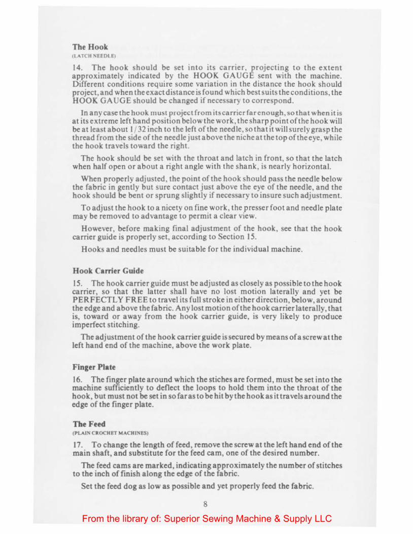
The Hook (! ATCH '\HOI El
14. The hook should be set into its carrier, projecting to the extent approximately indicated by the HOOK GAUGE sent with the machine. Different conditions require some variation in the distance the hook should project, and when the exact distance is found which best suits the conditions, the HOOK GAUGE should be changed if necessary to correspond.
In any case the hook must project from itscarricrfarenough, so that when it is at its extreme left hand position below the work, the sharp point oft he hook will beat least about 1/ 32 inch to the left of the needle,sothatit willsurelygraspthe thread from the side of the needle just above the niche at the top of the eye, while the hook travels toward the right.
The hook should be set with the throat and latch in front, so that the latch when half open or about a right angle with the shank, is nearly horizontal.
When properly adjusted, the point of the hook should pass the needle below the fabric in gently but sure contact just above the eye of the needle, and the hook should be bent or sprung slightly if necessary to insure such adjustment.
To adjust the hook to a nicety on fine work, the presser foot and needle plate may be removed to advantage to permit a clear view.
However, before making final adjustment of the hook. see that the hook carrier guide is properly set, according to Section 15.
Hooks and needles must be suitable for the individual machine.
Hook Carrier Guide
15. The hook carrier guide must be adjusted as closely as possible to the hook carrier, so that the latter shall have no lost motion laterally and yet be PERFECTLY FREE to travel its full stroke in either direction, below, around the edge and above the fabric. Any lost motion of the hook carrier laterally, that is, toward or away from the hook carrier guide, is very likely to produce imperfect stitching.
The adjustment of the hook carrier guide is secured by means of a screw at the left hand end of the machine, above the work plate.
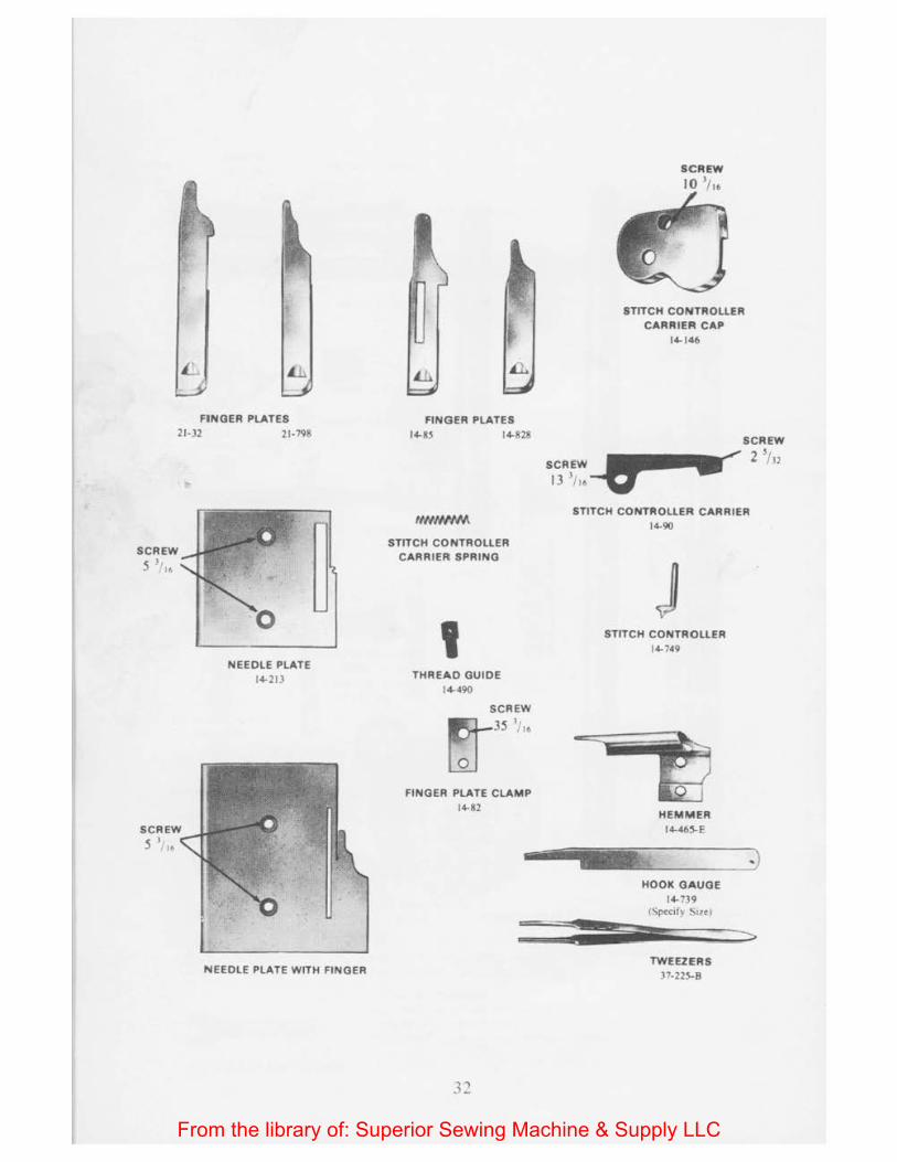
Finger Plate
16. The finger plate around which the stiches are formed, must be set into the machine sufficiently to deflect the loops to hold them into the throat of the hook, but must not be set in so far as to be hit by the hook as it travels around the edge of the finger plate.
The Feed (PLAI' CROCHET MACHINES)
17. To change the length of feed, remove the screw at the left hand end of the main shaft, and substitute for the feed cam, one of the desired number.
The feed cams are marked, indicating approximately the number of stitches to the inch of fmish along the edge of the fabric.
Set the feed dog as low as possible and yet properly feed the fabric .
8
From the library of: Superior Sewing Machine & Supply LLC
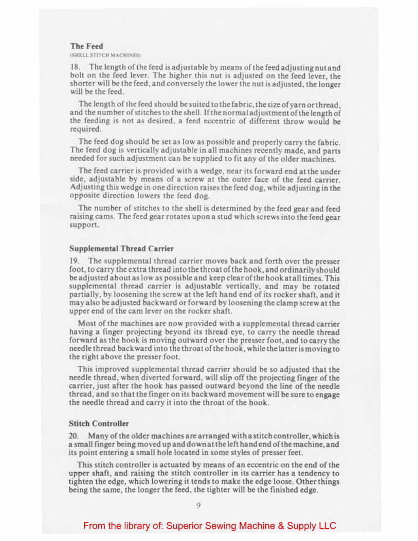
The Feed (SHELL STITC II "'A("HI'ES)
18. The length of the feed is adjustable by means of the feed adjusting nut and bolt on the feed lever. The higher this nut is adjusted on the feed lever, the shorter will be the feed, and conversely the lower the nut is adjusted, the longer will be the feed.
The length of the feed should be suited to the fabric, the size of yarn or thread, and the number of stitches to the shell. If the normal adjustment of the length of the feed ing is not as desired, a feed eccentric of different throw would be required.
The feed dog should be set as low as possible and properly carry the fabric. The feed dog is vertically adjustable in all machines recently made, and parts needed for such adjustment can be supplied to fit any of the older machines.
The feed carrier is provided with a wedge, near its forward end at the under side, adj ustable by means of a screw at the outer face of the feed carrier. Adjusting this wedge in one direction raises the feed dog, while adjusting in the opposite direction lowers the feed dog.
The number of stitches to the shell is determined by the feed gear and feed raising cams. The feed gear rotates upon a stud which screws into the feed gear support.
Supplemental Thread Carrier
19. The supplemental thread carrier moves back and forth over the presser foot, to carry the extra thread into the throat oft he hook, and ordinarily should be adjusted about as low as possible and keep clear of the hook a tall times. This supplemental thread carrier is adjustable vertically, and may be rotated partially, by loosening the screw at the left hand end of its rocker shaft, and it may also be adjusted backward or forward by loosening the clamp screw at the upper end of the cam lever on the rocker shaft.
Most of the machines are now provided with a supplemental thread carrier having a finger projecting beyond its thread eye, to carry the needle thread forward as the hook is moving outward over the presser foot, and to carry the needle thread backward into the throat of the hook , while the latter is moving to the right above the presser foot.
This improved supplemental thread carrier should be so adjusted that the needle thread, when diverted forward , will slip off the projecting finger of the carrier, just after the hook has passed outward beyond the line of the needle thread, and so that the finger on its backward movement will be sure to engage the needle thread and carry it into the throat of the hook.
Stitch Controller
20. Many of the older machines are arranged with a stitch controller, which is a small finger being moved up and down at the left hand end of the machine, and its point entering a small hole located in some styles of presser feet.
This stitch controller is actuated by means of an eccentric on the end of the upper shaft, and raising the stitch controller in its carrier has a tendency to tighten the edge, which lowering it tends to make the edge loose. Other things being the same, the longer the feed , the tighter will be the finished edge.
9
From the library of: Superior Sewing Machine & Supply LLC
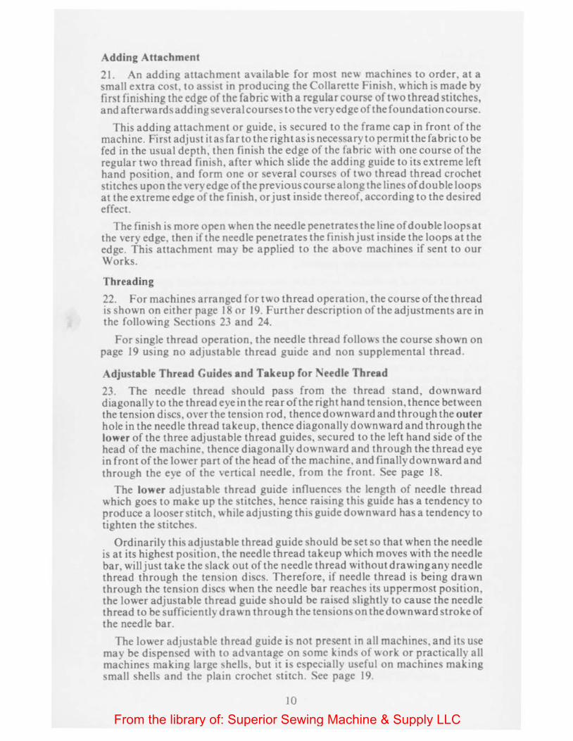
Adding Attachment
21. An adding attachment available for most ne\.\ machines to order. at a small extra cost. to asstst tn producing the Collarette Finish. which is made by first finishing the edge of the fabric with a regular course of two thread stitches, and afterwards adding several courses to the very edge of the foundation course.
This adding attachment or guide. is secured to the frame cap in front of the machine. First adjust it as far to the right as is necessary to permit the fabric to be fed in the usual depth, then finish the edge of the fabric with one course of the regular two thread finish, after which slide the adding guide to its extreme left hand position, and form one or several courses of two thread thread crochet stitches upon the very edge of the previous course along the lines of double loops at the extreme edge of the finish. or just inside thereof, according to the desired effect.
The finish is more open when the needle penetrates the line of double loops at the very edge. then if the needle penetrates the finish just inside the loops at the edge. This attachment may be applied to the above machines if sent to our Works.
Threading
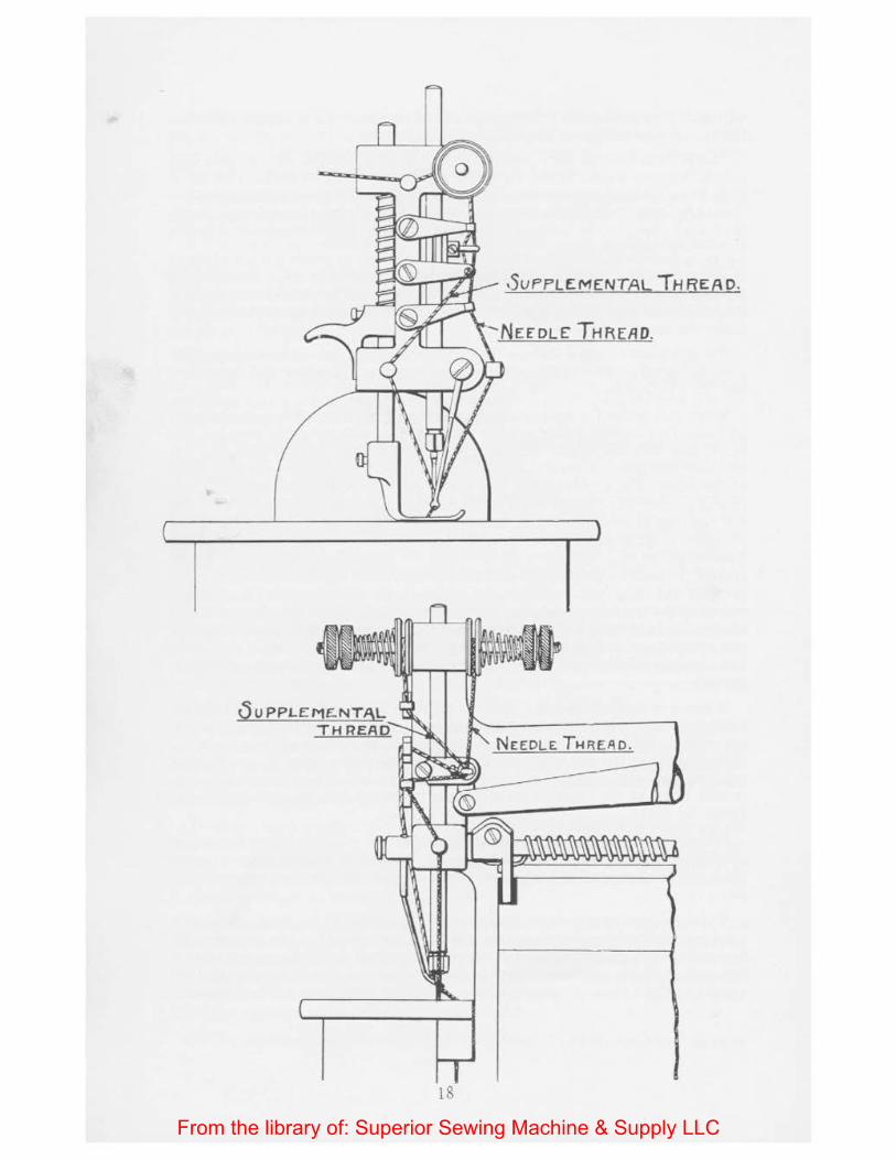
22. For machines arranged for two thread operation, the course of the thread is shown on either page 18 or 19. Further description of the adjustments are in the following Sections 23 and 24.
For single thread operation, the needle thread follows the course shown on page 19 using no adjustable thread guide and non supplemental thread.
Adjustable Thread Guides and Takeup for Needle Thread
23. The needle thread should pass from the thread stand, d ownward diagonally to the thread eye in the rear of the right hand tension, thence between the tension discs, over the tension rod, thence downward and through the outer hole in the needle thread takeup, thence diagonally downward and through the lower of the three adjustable thread guides, secured to the left hand side of the head of the machine. thence diagonaUydownward and through the thread eye in front of the lower part of the head of the machine, and finally downward and through the eye of the vertical needle, from the front. See page 18.
The lower adjustable thread guide influences the length of needle thread which goes to make up the stitches, hence raising this guide has a tendency to produce a looser stitch, while adjusting this guide downward has a tendency to tighten the stitches.
Ordinarily this adjustable thread guide should be set so that when the needle is at its highest position, the needle thread takeup which moves with the needle bar, will just take the slack out of the needle thread withoutdrawinganyneedle thread through the tension discs. Therefore, if needle thread is being drawn through the tension discs when the needle bar reaches its uppermost position, the lower adjustable thread guide should be raised slightly to cause the needle thread to be sufficiently drawn through the tensions on the downward stroke of the needle bar.
The lower adjustable thread guide is not present tn all machines. and its use may be dispensed with to advantage on some ktnds of \.\Ork or practically all machines making large shells. but it is especially useful on machines making small shells and the plain crochet stitch. See page 19.
10
From the library of: Superior Sewing Machine & Supply LLC
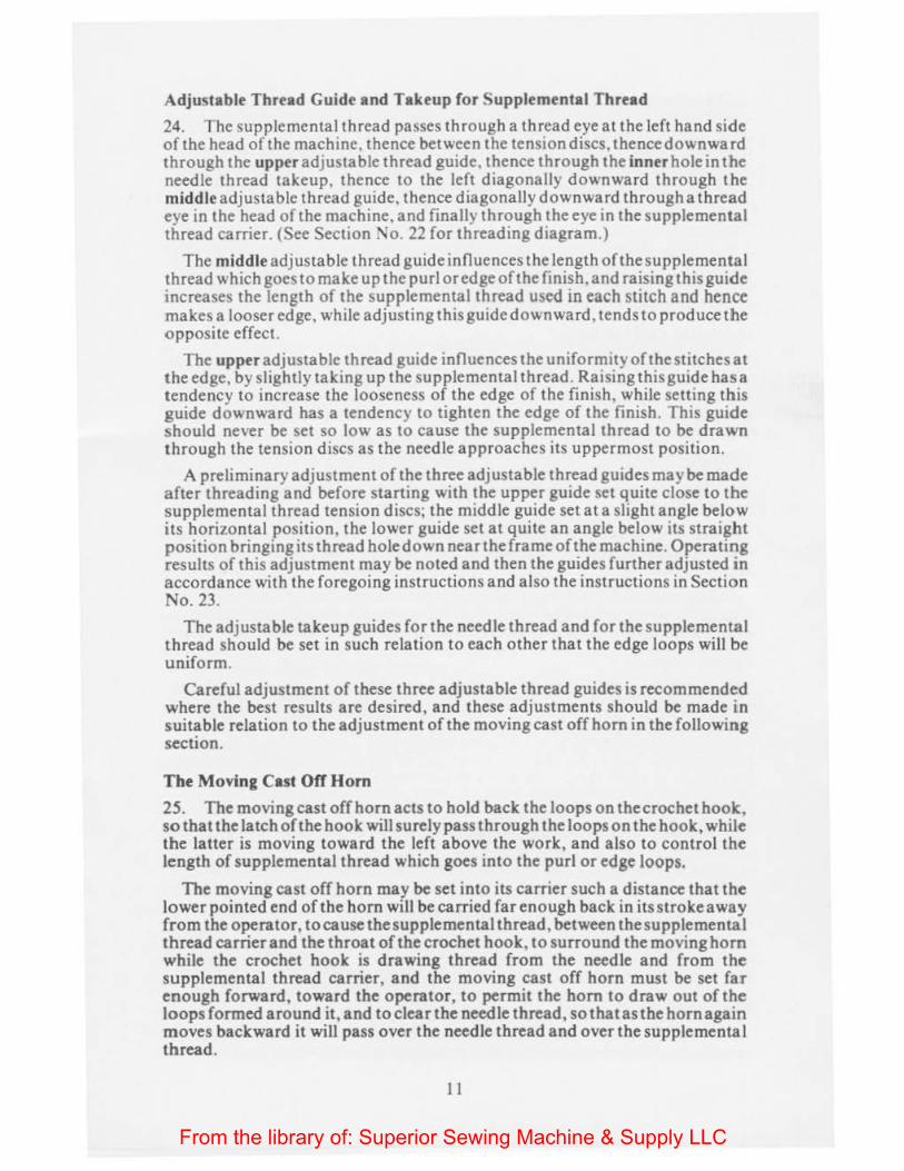
Adjustable Thread Guide and Takeup for Supplemental Thread
24. The supplemental thread passes through a thread eye at the left hand side of the head of the machine, thence between the tension discs. thencedownwa rd through the upper adjustable thread guide. thence through the inner hole in the needle thread takeup, thence to the left diagonally downward through the middle adjustable thread guide, thence diagonally downward through a thread eye in the head of the machine, and finally through the eye in the supplemental thread carrier. (See Section ~o. 22 for threading diagram.)
The middle adjustable thread guide influences the length of the supplemental thread which goes to make up the purl or edge of the finish, and raising this guide increases the length of the supplemental thread used in each stitch and hence makes a looser edge, while adjusting this guide downward, tends to produce the opposite effect.
The upper adjustable thread guide influences the uniformity of the stitches at the edge, by slightly taking up the supplemental thread. Raising this guide has a tendency to increase the looseness of the edge of the finish, while setting this guide downward has a tendency to tighten the edge of the finish. This guide should never be set so low as to cause the supplemental thread to be drawn through the tension discs as the needle approaches its uppermost position.
A preliminary adjustment of the three adjustable thread guides maybe made after threading and before starting with the upper guide set quite close to the supplemental thread tension discs; the middle guide set at a slight angle below lts horizontal position, the lower guide set at quite an angle below its straight position bringing its thread hole down nearthe frame of the machine. Operating results of this adjustment may be noted and then the guides further adjusted in accordance with the foregoing instructions and also the instructions in Section No. 23.
The adjustable take up guides for the needle thread and for the supplemental thread should be set in such relation to each other that the edge loops will be uniform.
Careful adjustment of these three adjustable thread guides is recommended where the best results are desired, and these adjustments should be made mn suitable relation to the adjustment of the moving cast off hom in the following section.
The Moving Cast Off Horn
25. The moving east off hom acts to hold back the loops on the crochet hook, so that the latch of the hook will surely pass through the loops on the hook, while the latter is moving toward the left above the work, and also to control the length of supplemental thread which goes into the purl or edge loops.
The moving cast off horn may be set into its carrier such a distance that the lower pointed end ofthe hom will be carried far enough back in its stroke away from the operator, to cause the supplemental thread, between the supplemental thread carrier and the throat of the crochet hook, to surround the moving hom while the crochet hook is drawing thread from the needle and from the supplemental thread carrier, and the moving cast off horn must be set far enough forward, toward the operator, to permit the hom to draw out of the loops formed around it, and to clear the needle thread, so that as the hom again moves backward it will pass over the needle thread and over the supplementa I thread.
11
From the library of: Superior Sewing Machine & Supply LLC

The sidewise adjustment of the moving cast off horn is made by loosening the clamp screw in the cast off carrier. and swinging the lower part of the horn toward or away from the presser foot. If the horn is set too far to the right, the stitches are likely to bind on the crochet hook, and if set too farto the left, it may not always pass over the supplemental thread, and cause an irregular finish. If the purl or chain along the edge is too loose, the horn may be adjusted slightly toward the operator. Be sure to firmly tighten the clamp screw after adjusting the horn.
For some classes of work the moving cast off horn may be considerably shortened (or adjusted towards the operator) so that the threads will not surround the cast off horn while the crochet hook draws the needle thread and supplemental thread above the work.
Stationary Cast Off Horn
26. Some of our machtnes are provided with an adjustably stationary cast off horn. which should be adjusted with its rear end about horizontal, just high enough to hold back the loops on the crochet hook while the latter is moving outward above the finger plate and presser foot, but not high enough to be hit by the hook.
Tensions
27. The tension of the two threads should be light but perceptible, and both may be about alike.
When a single thread finish is desired, remove the supplemental thread without change or adjustment of the machine, except possibly the tension of the needle thread.
When two threads are used in the needle, each thread should be passed through a separate tensiOn, that is, the extra thread used should be passed through the tension provided for the usual supplemental thread.
Thread Stops
28. A thread stop is attached to the presser foot in rna ny of the styles 22 and 27 machines. This thread stop is for the purpose of preventing the needle thread from passing back so far that it may not be caught by the crochet hook, as the latter travels from left to nght above the presser foot. The thread stop should be adjusted as far back as possible and yet not permit the needle thread to pass back far enough to allow the crochet hook to pass in front of it.
Fabric Guard
29. Some of the shell stitch machines are prov1ded w11h a fabric guard. which should project somewhat above the edge of the fabric, outside the purl or chain at the edge of the finish, and assist in holding the threads from previous loops while the crochet hook is drawing th reads through the old loops to form a new set of loops. In other words, it acts to help the crochet hook to shed its loops while making new loops, and for this purpose should be set as near to the edge of the finger plate as is practicable and have ample space fort he free passage of the loops. and it should also be set as near the path of the crochet hook as possible, and yet never permit the hook to come in contact with it.
Eight Stitch Shells
30. When using the eight stitch feed gear. the feed gear support must be placed in its groove in the left hand face of the machine below the work plate, with its
12
From the library of: Superior Sewing Machine & Supply LLC
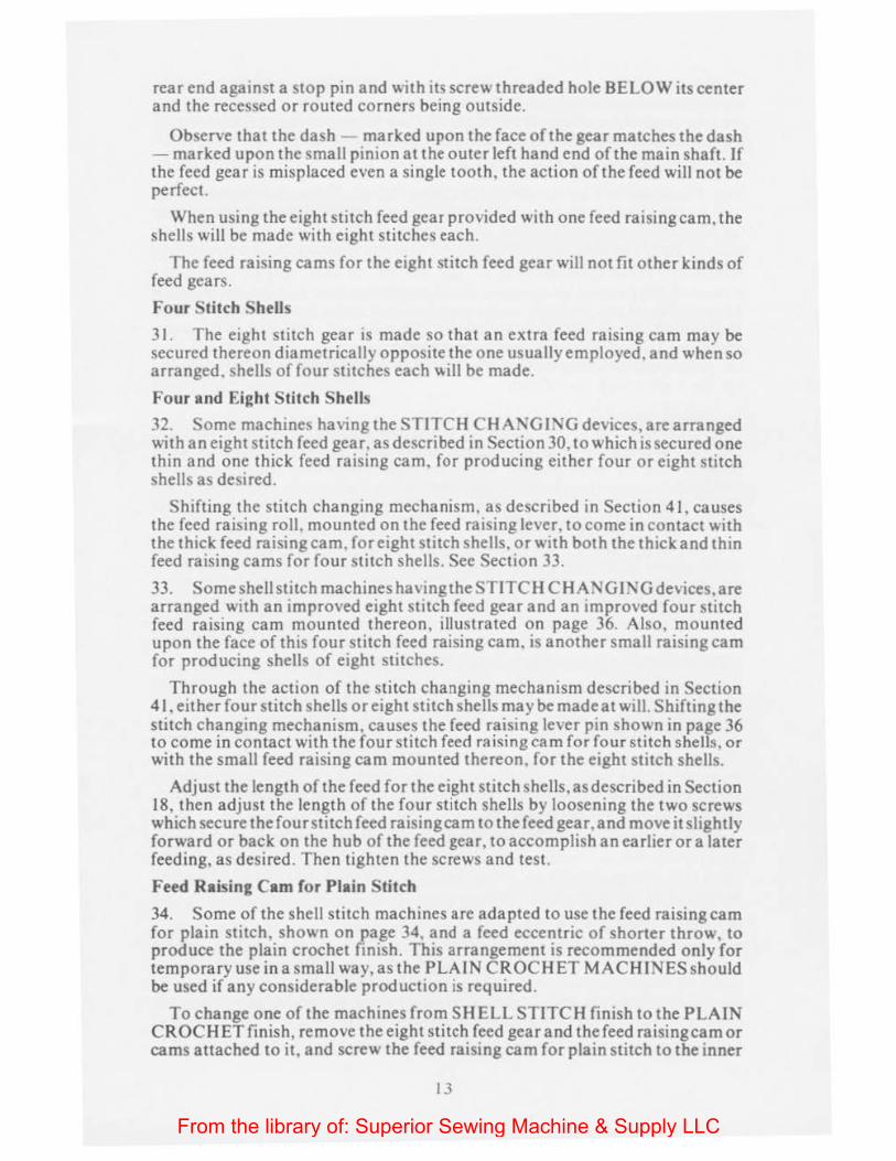
rear end against a stop pin and with its screw threaded hole BELOW its center and the recessed or routed corners being outside.
Observe that the dash - marked upon the face of the gear matches the dash -marked upon the small pinion at the outer left hand end of the main shaft. If the feed gear is misplaced even a single tooth, the action of the feed will not be perfect.
When using the eight stitch feed gear provided with one feed raising cam, the shells will be made with eight stitches each.
The feed ra1sing cams for the eight stitch feed gear will not fit other kinds of feed gears.
Four Stitch Shells
31. The eight stitch gear is made so that an extra feed raising cam may be secured thereon diametrically opposite the one usually employed , and when so arranged. shells of four stitches each ~ill be made.
Four and Eight Stitch Shells
32. Some machines having the STITCH C HANGING devices, are arranged with an eight stitch feed gear, as described in Section 30, to which is secured one thin and one thick feed raising cam, for producing either four or eight stitch shells as desired.
Shifting the stitch changing mechanism. as described in Section 41, causes the feed raising roll. mounted on the feed raising lever. to come in contact with the thick feed raising cam. for eight stitch shells. or with both the thick and thin feed raising cams for four stitch shells. See Section 33.
33. Some shell stitch machines having the STITCH C HANGI!'\G devices, are arranged with an improved eight stitch feed gear and an improved four stitch feed raising cam mounted thereon, illustrated on page 36. Also, mounted upon the face of this four stitch feed raising cam. is another small raising cam for producing shells of eight stitches.
Through the action of the stitch changing mechanism described in Section 4 1. either four stitch shells or eight stitch shells may be made at will. Shifting the stitch changing mechanism, causes the feed raising lever pin shown in page 36 to come in contact with the four stitch feed raising cam for four stitch shells, or with the small feed raising cam mounted thereon. for the eight stitch shells.
Adjust the length of the feed forthe eight stitch shells, as described in Section 18, then adjust the length of the four stitch shells by loosening the two screws which secure thefourstitch feed raising cam to the feed gear.and move it slightly forward or back on the hub of the feed gear, to accomplish an earlier or a later feeding, as desired. Then tighten the screws and test.
Feed Raising Cam for Plain Stitch
34. Some of the shell stitch machines are adapted to use the feed raising cam for plain stitch, shown on page 34, and a feed eccentric of shorter throw, to produce the plain crochet finish. This arrangement is recommended only for temporary use ina small way,as the PLAIN CR OCH ET MACHINES should be used if any considerable production is required.
To change one of the machines from SH ELL STITCH finish to the PLAIN CROCHET finish, remove the eight stitch feed gear and the feed raising cam or cams attached to it, and screw the feed raising cam for plain stitch to the inner
13
From the library of: Superior Sewing Machine & Supply LLC
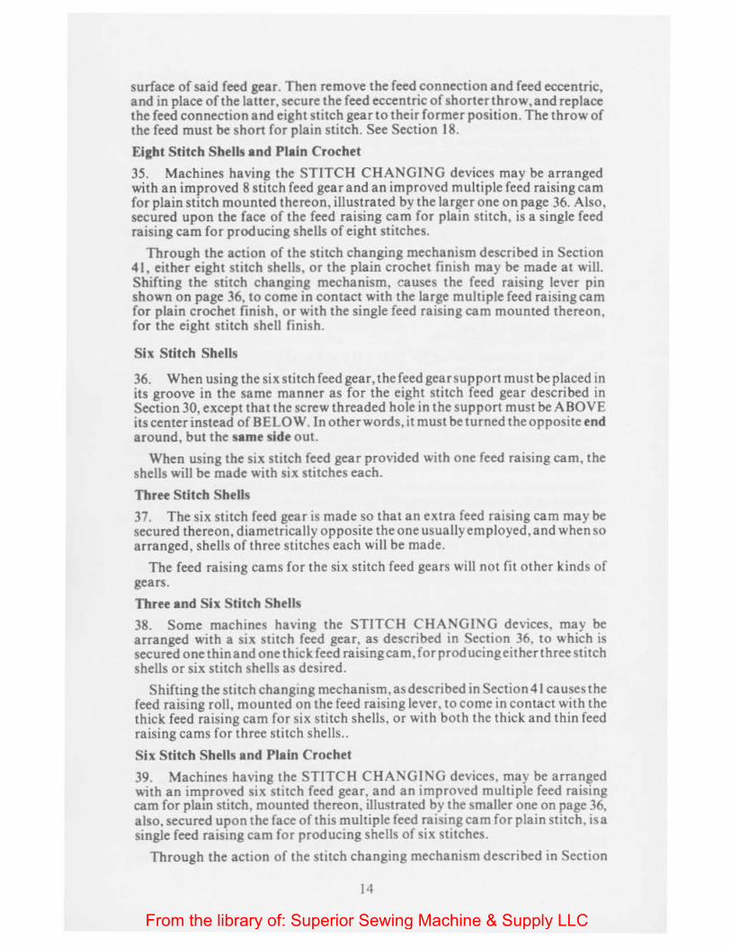
surface of said feed gear. Then remove the feed connection and feed eccentric, and in place of the latter, secure the feed eccentric of shorterthrow, and replace the feed connection and eight stitch gear to their former position. T he throw of the feed must be short for plain stitch. See Section 18.
Eight Stitch Shells and Plain Crochet
35. Machines having the STITCH CHANGING devices may be arranged with an improved 8 stitch feed gear and an improved multiple feed raising cam for plain stitch mounted thereon, illustrated by the larger one on page 36. Also, secured upon the face of the feed raising cam for plain stitch, is a single feed raising cam for producing shells of eight stitches.
Through the action of the stitch changing mechanism described in Section 41, either eight stitch shells, or the plain crochet finish may be made at will. Shifting the stitch changing mechanism, causes the feed raising lever pin shown on page 36, to come in contact with the large multiple feed raising cam for plain crochet finish, or with the single feed raising cam mounted thereon, for the eight stitch shell finish.
Six Stitch Shells
36. When using the six stitch feed gear, the feed gear support must be placed in its groove in the same manner as for the eight stitch feed gear described in Section 30, except that the screw threaded hole in the support must be ABOVE its center instead of BELOW. In other words, it must be turned the opposite end around, but the same side out.
When using the six stitch feed gear provided with one feed raising cam, the shells will be made with six stitches each.
Three Stitch Shells
37. The six stitch feed gear is made so that an extra feed raising cam may be secured thereon, diametrically opposite the one usually employed, and when so arranged, shells of three stitches each will be made.
The feed raising cams for the six stitch feed gears will not fit other kinds of gears.
Three and Six Stitch Shells
38. Some machines having the STITCH CHANGING devices, may be arranged with a six stitch feed gear, as described in Section 36. to which is secured one thin and one thick feed raising cam, forproducingeitherthreestitch shells or six stitch shells as desired.
Shifting the stitch changing mechanism, as described in Section41 causes the feed raising roll, mounted on the feed raising lever, to come in contact with the thick feed raising cam for six stitch shells, or with both the thick and thin feed raising cams for three stitch shells ..
Six Stitch Shells and Plain Crochet
39. Machines having the STITCH CHANGING devices, may be arranged with an improved six stitch feed gear, and an improved multiple feed raising cam for plam stitch, mounted thereon, illustrated by the smaller one on page 36, also, secured upon the face of this multiple feed raising cam for plain stitch, is a single feed raising cam for producing shells of six stitches.
Through the action of the stitch changing mechanism described in Section
14
From the library of: Superior Sewing Machine & Supply LLC
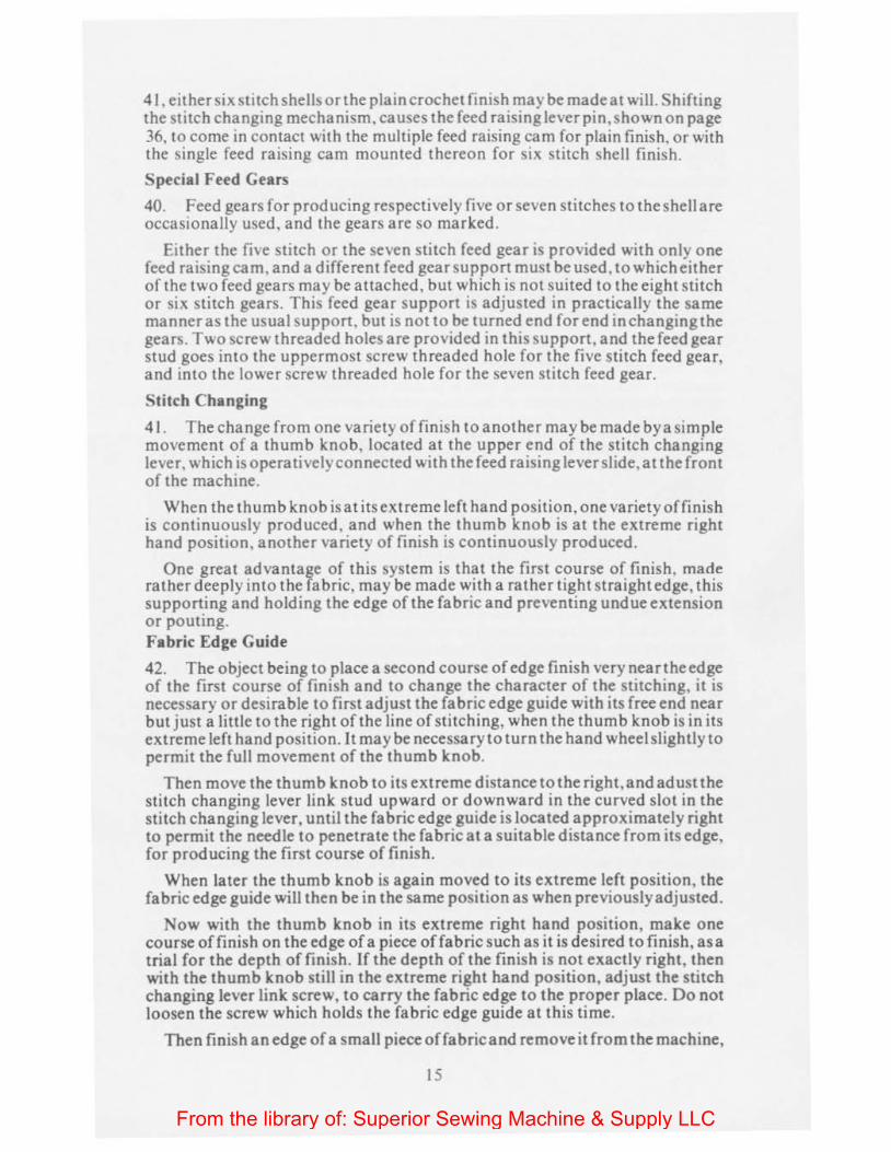
41, either six stitch shell!> orthe plain crochet finish may be made at will. Shifting the stitch changing mechanism, causes the feed raising lever pin, shown on page 36, to come in contact with the multiple feed raising cam for plain finish, or with the single feed raising cam mounted thereon for six stitch shell finish.
Special Feed Gears
40. Feed gears for producing respectively five or seven stitches to the shell are occasionally used, and the gears arc so marked.
Either the five stitch or the seven stitch feed gear is provided with only one feed raising cam, and a different feed gear support must be used, to which either of the two feed gears may be attached, but which is not suited to the eight stitch or six stitch gears. This feed gear support is adjusted in practically the same manner as the usual support. but is not to be turned end for end in changing the gears. Two screw threaded holes are provided in this support, and the feed gear stud goes into the uppermost screw threaded hole for the five stitch feed gear, and into the lower screw threaded hole for the seven stitch feed gear.
Stitch Changing
41. The change from one variety of finish to another maybe made by a simple movement of a thumb knob, located at the upper end of the stitch changing lever, which is operatively connected with the feed raising lever slide, at the front of the machine.
When the thumb knob is at its extreme left hand position, one variety of finish is continuously produced, and when the thumb knob is at the extreme right hand position, another variety of finish is continuously produced.
One great advantage of this system is that the first course of finish, made rather deeply into the fabric. may be made with a rather tight straightedge, this supporting and holding the edge of the fabric and preventing undue extension or pouting. Fabric Edge Guide
42. The object being to place a second course of edge finish very near the edge of the first course of finish and to change the character of the stitching, it is necessary or desirable to first adjust the fabric edge guide with its free end near but just a little to the right of the line of stitching, when the thumb knob is in its extreme left hand position. It may be necessary to turn the hand wheel slightly to permit the full movement of the thumb knob.
Then move the thumb knob to its extreme distance to the right,andadust the stitch changing lever link stud upward or downward in the curved slot in the stitch changing lever, until the fabric edge guide is located approximately right to permit the needle to penetrate the fabric at a suitable distance from its edge, for producing the first course of finish.
When later the thumb knob is again moved to its extreme left position, the fabric edge guide will then be in the same position as when previously adjusted.
Now with the thumb knob in its extreme right hand position, make one course of finish on the edge of a piece of fabric such as it is desired to finish, as a trial for the depth of finish. If the depth of the finish is not exactly right, then with the thumb knob still in the extreme right hand position, adjust the stitch changing lever link screw, to carry the fabric edge to the proper place. Do not loosen the screw which holds the fabric edge guide at this time.
Then finish an edge of a small piece offabricand remove it from the machine,
IS
From the library of: Superior Sewing Machine & Supply LLC

and afterwards set the thumb know to its extreme left positon and make the second course along the edge of the first course. Then make any very slight adjustment of the fabric edge guide which may be necessary, by means of the screw which passes through the fabric edge guide shank.
The stitch changing lever link is made so that its right hand end may be swung upward to unhook it, and thus disconnect it from the stitch changing lever.
I fit is desired to make a deep finish of one kind fora time, and at another time to make a deep finish of the other kind , of the two possible varieties, set the thumb knob to the extreme right hand position and then unhook the stitch changing lever link, without at all disturbing the fabric edge guide, and the machine will be prepared to make one of the two possible kinds of finish, both deeply into the fabric.
Taping
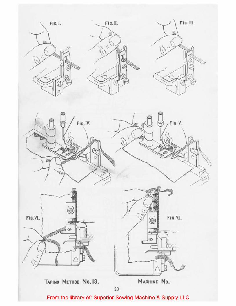
43. The cuts on page 20 illustrate the method of handling the tape or ribbon in machines which are provided with a presser foot lifter operated by a treadle, thus permitting the free use of the hands of the operator.
To introduce the tape, commence with the needle above the cloth and the crochet hook holding the thread well to the right, as shown in Figure IV, and with the stitches properly formed . The tape or ribbon is passed through a hole in the flat tension spring, from right to left, and naturally passes through on opening in the tension spring support, when it is grasped by the thumb and finger of the left hand as shown in Figure I. The end of the tape is then carried forward and upward, causing the rear edge of the tape to lead upward in the vertical slot from the round hole in the flat tension spring, as shown in Figure II.
The tape is then carried backward and to the left, which carries it into the recess in the upper end of the tape tension support as shown in Figure II I. Thence the tape is carried downward and to the fabric on the work plate, then backward and under a projecting horn or guide, as shown in Figure IV, when the presser foot must be raised by the foot of the operator, and the tape carried rearward under the presser foot, with the end of the tape extending beyond the presser foot , to provide desired length, as shown in Figure VI.
The tape guide and fabricedgeguideshould be so adjusted that theneedlewill not penetrate the tape while being fed along with the fabric. Then operate the machine until the edge of the fabric is finished the desired distance, stopping with the needle above the work and the crochet hook holding the needle thread as shown in Figures IV and V.
To discontinue the inclusion of the tape within the shells, draw through the tension a suitable length of the tape to form one end of the tie or bow, and sever the tape about an inch from the tape tensionsupport,leavingtheend of the tape projecting conveniently to be grasped later, still holding the tape with the left thumb and finger, as shown in Figure VI.
Raise the presser foot by the foot lifter treadle, hold down the fabric with the right hand and pass the free end of tape rearward and under the presser foot, draw the tape sufficiently toclearthe needle and then thefreeend of the tape will be under the presser foot and over the edge finish, when the edge finish may be continued or the goods may be pushed to the left away from the needle and the machine operated a few stitches to "chain out."
On the later machine, a trough shaped taped guide, as illustrated on page 36
16
From the library of: Superior Sewing Machine & Supply LLC
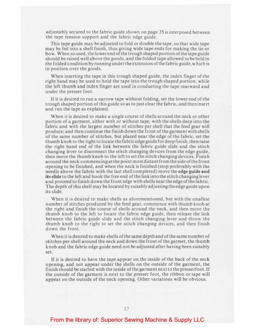
adjustably secured to the fabric guide shown on page 35 is interposed between the tape tension support and the fabric edge guide.
This tape guide may be adjusted to fold or double the tape, so that wide tape may be fed into a shell finish, thus giving wide tape ends for making the tie or bow. When so used, the lower end oft he trough shaped portion of the tape guide should be raised well above the goods, and the folded tape allowed to be held in the folded condition by running under the extension of the fabric guide, which is in position over the goods.
When inserting the tape in this trough shaped guide, the index finger of the right hand may be used to hold the tape into the trough shaped portion, while the left thumb and index finger are used in conducting the tape rearward and under the presser foot.
If it is desired to run a narrow tape without folding, set the lower end of the trough shaped portion of this guide so as to just clear the fabric, and then insert and run the tape as explained.
When it is desired to make a single course of shells around the neck or other portion of a garment, either with or without tape, with the shells deep into the fabric and with the largest number of stitches per shell that the feed gear w~IJ produce; and then continue the finish down the front of the garment with shells of the same number of stitches, but placed near the edge of the fabric. set the thumb knob to the right to locate thefabricedgeguide for deep finish, then raise the right hand end of the link between the fabric guide slide and the stitch changing lever to disconnect the stitch changing devices from the edge guide, then move the thumb knob to the left to set the stitch changing devices. Finish around the neck commencing at the point most distant from the side of the front opening to be finished, and when the neck is finished (stop preferably with the needle above the fabric with the last sheJJ completed) move the edge guide and its slide to the left and hook the free end of the link into thestitchchanging lever and proceed to finish down the front edge with shells near the edge of the fabric. The depth of this shell may be located by suitably adjusting the edge guide upon ins slide.
When it is desired to make shells as aforementioned. but with the smallest number of stitches produced by the feed gear, commence with thumb knob at the right and finish the course of shells around the neck, and then move the thumb knob to the left to locate the fabric edge guide, then release the link between the fabric guide slide and the stitch changing lever and throw the thumb knob to the right to set the stitch changing devices, and then fintsh down the front.
When it is desired to make shells ofthesamedepth and ofthesamenumberof stitches per shell around the neck and down the front of the garmet, the thumb knob and the fabric edge guide need not be adjusted after having been suitably set.
If it is desired to have the tape appear on the inside of the back of the neck opening, and not appear under the shells on the outside of the garment, the finish should be started with the inside of the garment next to the presserfoot. If the outside of the garment is next to the presser foot, the ribbon or tape wimt appear on the outside of the neck opening. Other variations will be obvious.
17
From the library of: Superior Sewing Machine & Supply LLC
.SuPPLEMENTAL THREAD.
18
From the library of: Superior Sewing Machine & Supply LLC

THREADING No.56. STYLE MACHINE No.
19
From the library of: Superior Sewing Machine & Supply LLC
Fis.I. fiG . m.
flo .VI . ftG.VJI.
TAPING METHOD No.l9. MACHINE No. 20
From the library of: Superior Sewing Machine & Supply LLC
Model 21-778 21-779
14-50 14-51 14-15
14-11
21-923 21-924 14-455 14-455-Q 14-76 ,/
21-75 21-788-A 21-788-C 21-788-E 21-788-F 21-788-G 21-788-H 21-788-K 21-790
21-791 21-792
21-789
21-926 21-930 21-930-A 21-927 14-680 14-826 14-907 14-914
14-945 21-66 21-763-B 21-763-C 21-877-B 14-831 14-902 21-794 21-805 21-879
21-808
ALPHA BETICAL INDEX
Adjustable Thread Gu1de Adjustable Thread Guide Adjustable Thread Guide Screw 5-3/16 Block Guide, Upper Block Guide, Lower Block Guide, Key Block Guide, Key Screw 4-3/16 Cam Lever Cam Lever Screw 6-3/16 Cam Lobe Indicator Cam Lobe Indicator Cam Roll Cam Roll, Barrel Shape Cast Off Horn Cast Off Horn Screw 6-3/ 16 Cast Off Horn Cast 0 ff Horn Cast Off Horn Cast Off Horn Cast Off Horn Cast Off Horn Cast Off Horn Cast Off Horn Cast Off Horn Carrier Cast 0 ff Horn Carrier Screw 13-3/16 Cast Off Horn Carrier Block Cast Off Horn Carrier Cap Cast 0 ff Horn Carrier Cap Screw 10-3/16 Cast Off Horn Clamp Cast Off Horn Clamp Screw 25-5/32 Edge Guide Indicator Edge Guide Indicator Bushing Edge Guide Indicator Bushing Edge Guide Indicator Scale Fabric Guard Fabric Guard Fabric Guard Fabric Guard Fabric Guard Screw 5-3/ 16 Fabnc Guard Fabric Guard Fabric Guard Fabnc Guard Fabric Guard Fabric Guide Fabric Guide Fabric Guide Fabric Guide Fabric Guide Fabnc Guide Screw 18-3 16 Fabnc Guide Washer 1-3/16 Fabric Guide Slide
21
From the library of: Superior Sewing Machine & Supply LLC
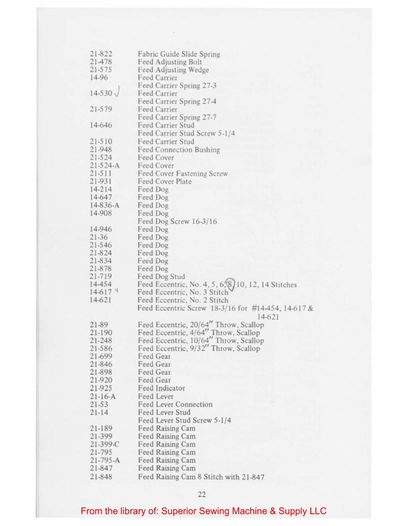
21-822 21-478 ::! 1-5 75 14-96
14-530 J 21-579
14-646
21-510 21-948 21-524 21-5 24-A 21-5 11 21-931 14-214 14-647 14-836-A 14-908
14-946 21-36 21-546 21-824 21-834 21-878 21-719 14-454 14-617 ... 14-621
21-89 21-190 21-248 21-586 21-699 21-846 21-898 21-920 21-925 21-16-A 21-53 21-14
21-189 21-399 21-399-C 21-795 21-795-A 21-847 21-848
Fabnc Guide Slide Spring Feed Adjusting Bolt f-eed Adjusting Wedge Feed Carrier Feed Carrier Spring ::!7-3 Feed Carner Feed Carner Spnng 27-4 Feed Carner Feed Carrier Spring ::!7-7 Feed Carrier Stud Feed Carrier Stud Screw 5-lr+ Feed Carrier Stud Feed Connection Bushing Feed Cover Feed Cover Feed Cover Fastening Screw Feed Cover Plate Feed Dog Feed Dog Feed Dog Feed Dog Feed Dog Screw 16-3/16 Feed Dog Feed Dog Feed Dog Feed Dog Feed Dog Feed Dog f-eed Dog Stud Feed Eccentric. :'\o. 4, 5, 6i) 10, 12, 14 Stnches Feed Eccentric. '\o. 3 Stitch Feed Eccentric. 'io. 2 Stitch Feed l:.ccentric Screw 18-3/ 16 for .1;14-454. 14-617 &
14-621 Feed Eccentric. 20/64" Throw, Scallop Feed Eccentric, 4/64" Throw, Scallop Feed Eccentric. 10/64" Throw, Scallop Feed Eccentric, 9/32" Throw, Scallop Feed Gear Feed Gear Feed Gear Feed Gear Feed Indicator Feed Lever Feed Lever Connection Feed Lever Stud Feed Lever Stud Screw 5-1/4 Feed Raising Cam Feed Raising Cam Feed Raising Cam Feed Raising Cam Feed Raising Cam Feed Raising Cam Feed Raising Cam 8 Stitch with 21-847
22
From the library of: Superior Sewing Machine & Supply LLC
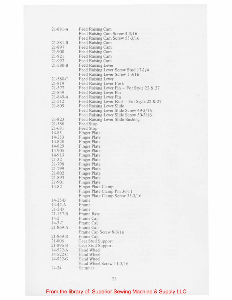
2 J -881-A
21-881-B 21-897 21-900 21-921 21-922 21-580-B
21-580-C 21-l:$19 21-577 21-849 21-849-A 21-512 21-809
21-823 21-588 21-681 14-85 14-253 14-828 14-829 14-905 14-913 21-32 21-798 21-799 21-802 21-893 21-901 14-82
14-25-B 14-42-A 21-2-D 21-157-B 14-2 14-3-C 21-869-A
2l-b69-B 21-1>06 21-896-B 14-522-A 14-522-C 14-522-G
14-34
Feed Raising Cam Feed Raising Cam Screw 4-3/16 Feed Raising Cam Screw 55-3/16 Feed Raising Cam Feed Raising Cam Feed Raising Cam Feed Raising Cam Feed Raising Cam Feed Raising Lever Feed Raising Lever Screw Stud 17-1/4 Feed Raising Lever Screw 1-3/16 Feed Raising Lever Feed Raismg Lever Fork Feed Raismg Lever Pin For Style 22 & 27 Feed Raismg Lever Pin Feed Raising Lever Pin Feed Raising Lever Roll For Style 22 & 27 Feed Raising Lever Slide Feed Raising Lever Slide Screw 49-3/16 Feed Raising Lever Slide Screw 50-3/16 Feed Raising Lever Slide Bushing Feed Stop Feed Stop £ inger Plate Finger Plate Finger Plate Finger Plate Finger Plate Finger Plate Finger Plate Finger Plate Finger Plate Finger Plate Finger Pia te Finger Plate Finger Plate Clamp Finger Plate Clamp Pin 36-11 Finger Plate Clamp Screw 35-3/ 16 Frame Frame Frame Frame Base Frame Cap Frame Cap Frame Cap Frame Cap Screw 8-3/ 16 Frame Cap Gear Stud Support Gear Stud Support Hand Wheel Hand Wheel lland Wheel Hanu Wheel Screw 11-3/ 16 !Iemmer
23
From the library of: Superior Sewing Machine & Supply LLC
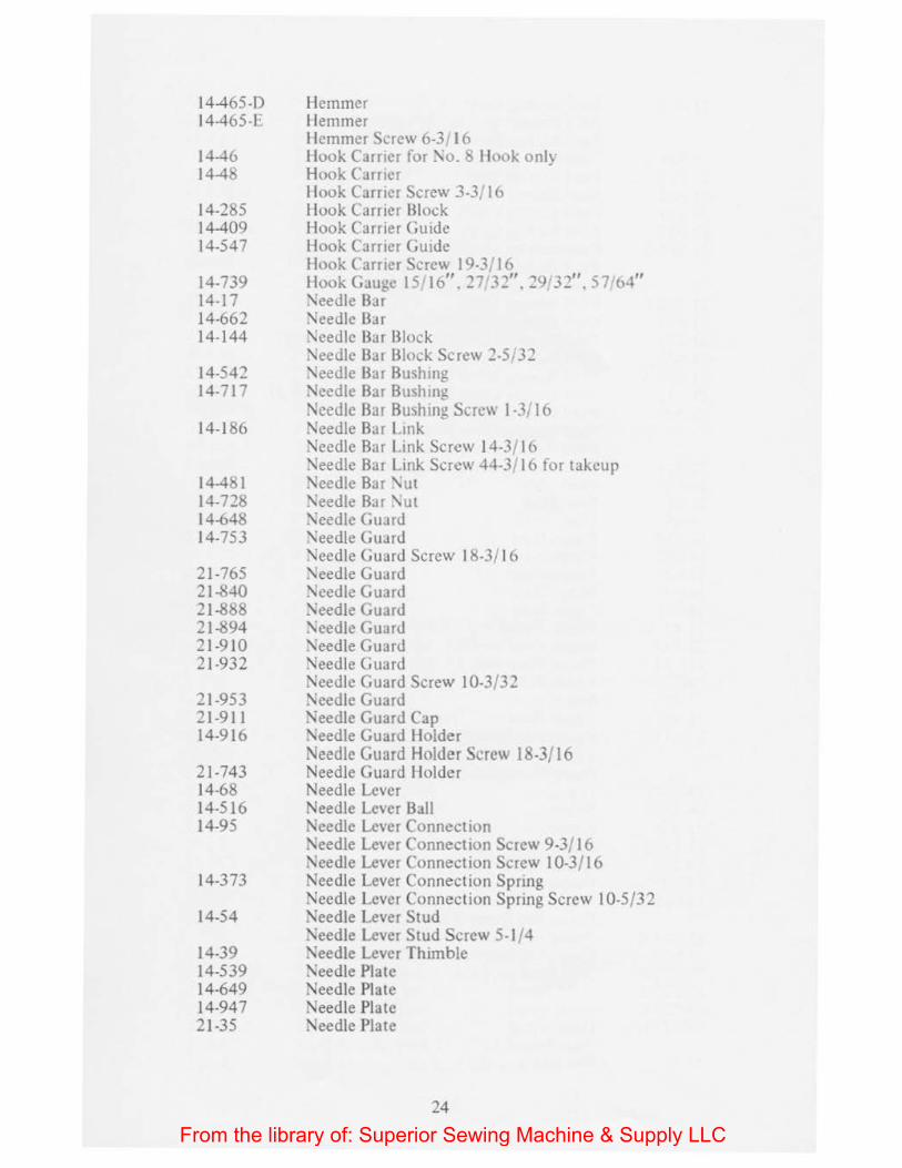
14-465-D 14-465-F
14-46 14-48
14-285 14-409 14-547
14-739 14-17 14-662 14-144
14-542 14-717
14-186
14-481 14-728 14-648 14-753
21 -765 21-840 21-888 21-894 21-910 21-932
21-953 21-911 14-916
21-743 14-68 14-516 14-95
14-373
14-54
14-39 14-539 14-649 14-947 21-35
Hemmer I Iemmer Hemmer Screw 6-3 16 Hook Carrier for :-..o. b !look onlv Hook Carrier -!look Carner Screw 3-3/ 16 !look Carner Block Hook Carrier Guide Hook Carner GUide Hook ( arrier Scre'' 19-3 16 Hook Gauge IS 16". 27 32". 29 32". 57/o4" '\ieetlle Bar Needle Bar Needle Bar Block \/eedle Bar Block Screw 2-5132 ~eedle Bar Bushmg Needle Bar B Jshmg Needle Bar Bushing Screw J -3/16 Needle Bar L mk i'-leedle Bar L111k Screw 14-3/ 16 Needle Bar L. ink Screw 44-3/ 16 for takcup Needle Bar '\ut ~eedle Bar '\ut :\eedle Guard '\eedle Guard "leedle Guard Screw 18-3/ 16 '\eedle Guard :-\eedle Guard :\eedle Guard '\eedle Guard \/eedle Guard Needle Guard Needle Guard Screw 10-3/3 2 Needle Guard Needle Guard Cap Needle Guard Holder Needle Guard Holder Screw 18-3/16 Needle Guard Holder Needle Lever Needle Lever Ball Needle Lever Connection 1'-oeedle Lever Connection Screw 9-3/ I 6 Needle Lever Connection Screw 10-3/16 Needle Lever Connection Spring Needle Lever Connection Spring Screw I 0-5/32 Needle Lever Stud :\eedle Lever Stud Screw 5-l/4 Xeedle Lever Thimble Needle Plate Needle Plate Needle Plate Needle Plate
24
From the library of: Superior Sewing Machine & Supply LLC
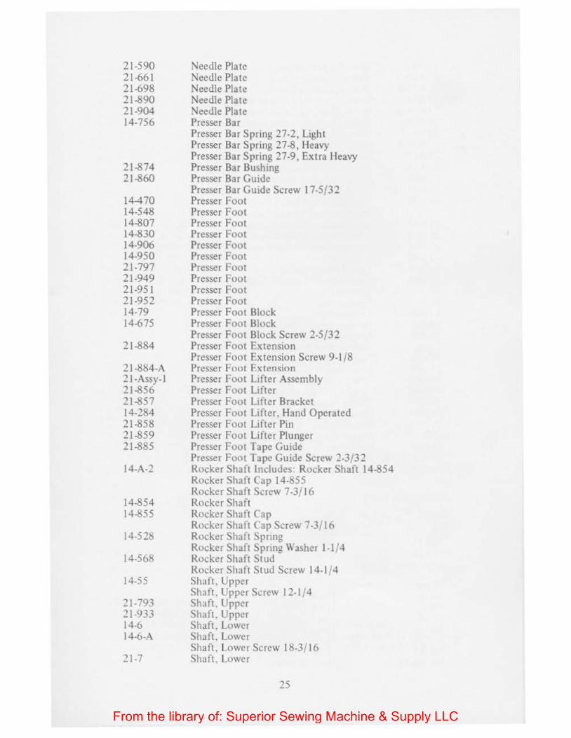
21-590 21-661 21-698 21-890 21-904 14-756
21-874 21-860
14-470 14-548 14-807 14-830 14-906 14-950 21-797 21-949 21-951 21-952 14-79 14-675
21-884
21-884-A 2 I -Assy-1 21-856 21-857 14-284 21-858 21-859 21-885
14-A-2
14-854 14-855
14-528
14-568
14-55
21-793 21-933 14-6 14-6-A
21-7
Needle Pia te Needle Plate Needle Plate Needle Plate Needle Plate Presser Bar Presser Bar Spring 27-2, Light Presser Bar Spring 27-8, Heavy Presser Bar Spring 27-9, Extra lleavy Presser Bar Bushing Presser Bar Guide Presser Bar Guide Screw 17-5/32 Presser Foot Presser Foot Presser Foot Presser Foot Presser Foot Presser Foot Presser Foot Presser Foot Presser Foot Presser Foot Presser Foot Block Presser Foot Block Presser Foot Block Screw 2-5/32 Presser Foot Extension Presser Foot Ex tension Screw 9-1 /8 Presser Foot Extension Presser Foot Lifter Assembly Presser Foot Lifter Presser Foot Lifter Bracket Presser Foot Lifter. Hand Operated Presser Foot Lifter Pin Presser Foot Lifter Plunger Presser Foot Jape Guide Presser Foot Tape Guide Screw 2-3/32 Rocker Shaft Includes: Rocker Shaft 14-854 Rocker Shaft Cap 14-855 Rocker Shaft Screw 7-3/ 16 Rocker Shaft Rocker Shaft Cap Rocker Shaft Cap Screw 7-3/16 Rocker Shaft Spnng Rocker Shaft Spnng Washer 1-1/4 Rocker Shaft Stud Rocker Shaft Stud Screw 14-1 /4 Shaft, Upper Shaft. Upper Screw 12-1/4 Shaft. Upper Shaft. Upper Shaft. Lower Shaft. Lower Shaft, Lower Screw 18-3/16 Shaft. Lower
From the library of: Superior Sewing Machine & Supply LLC
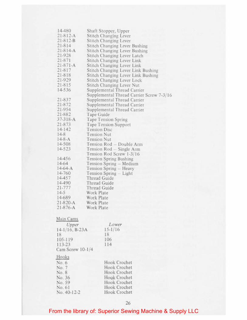
14-480 21-812-A 21-812-B 21-814 21-814-A 21-928 21-871 21-871-A 21-8 I 7 21-818 21-929 21-815 14-536
21-837 21-872 21-954 21-882 37-318-A 21-873 14-142 14-8 14-8-A 14-508 14-523
14-456 14-64 14-64-A 14-760 14-457 14-490 21-777 14-S 14-689 2 1-820-A 21 -876-A
Main Cams
Shaft Stopper, Upper Stitch Changing Lever Stitch Changing Lever Stitch Changing Lever Bushing Stitch Changing Lever Bushing Stitch Changing Lever Latch Stitch Changing Lever Link Stitch Changing Lever Link Stitch Changing Lever Link Bushing Stitch Changing Lever Link Bushing Stitch Changing Lever Lock Stitch Changing Lever Nut Supplemental Thread Carrier Supplemental Thread Carrier Screw 7-3/ 16 Supplemental Thread Carrier Supplemental Thread Carrier Supplemental Thread Carrier Tape Guide Tape Tension Spring Tape Tension Support Tension Disc Tension Nut Tension Nut Tension Rod -Double Arm Tension Rod Single Arm Tension Rod Screw 1-3/ 16 Tension Spring Bushing Tension Spring - Medium Tension Spring - Heavy Tension Spring Light Thread Guide Thread Guide Thread Guide Work Plate Work Plate Work Plate Work Plate
Upper 14-1/16, B-23A 18
Lower 15-1/16 18
105-119 I 13-23 Cam Screw 10-1 /4
I looks No.6 No.7 No.8 No. 36 No. 59 No. 61 No. 40-12-2
106 114
Hook Crochet Hook Crochet Hook Crochet Hook Crochet Hook Crochet Hook Crochet Hook Crochet
26
From the library of: Superior Sewing Machine & Supply LLC
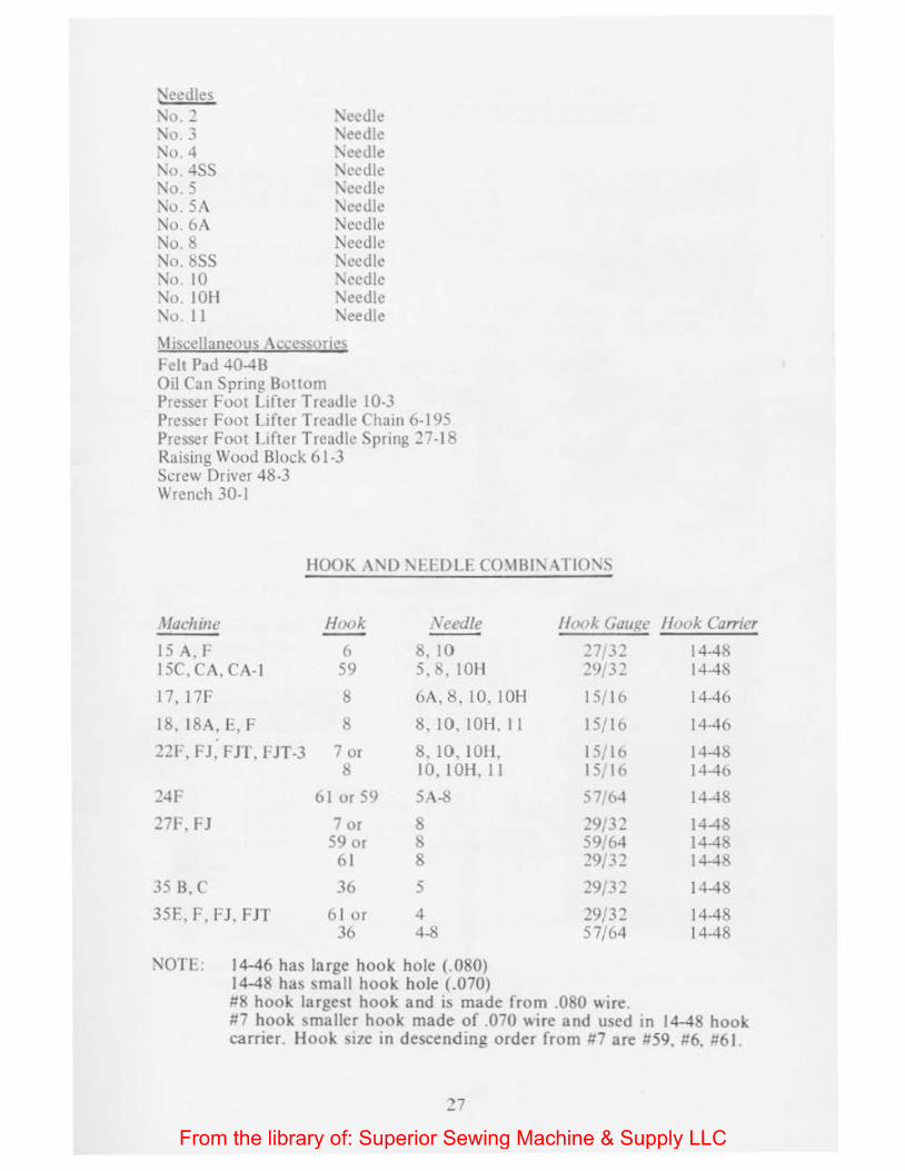
~ccdles
'\o. 2 '\o . 3 '\o 4 '\o -lSS No.5 :>.o. SA :\o 6A No.8 \Jo. 8SS '\;o I 0 \lo IOH '\o. II
'\ecdlc \Jeedle '\cedle \Jcedlc \:ecdle \Jecdle Needle Needle Needle '\ecdlc \Jecdlc '\eedlc
\l•sccllaneous Accessone\ reh Pad -l0--ll3 Oil Can Spring Bottom Presser Foot Lifter Treadle 10-3 Presser Foot Lifter Treadle Chain 6-195 Presser Foot Lifter Treadle Spring 27-18 Raising Wood Block 61-3 Screw Driver 48-3 Wrench 30-1
HOOK A '\D '\E£DLE CmiBI'\ ATIO'\S
Machine Hook Xeedle
15 A, P 6 8, 10 15C,CA,CA-1 59 5, 8. lOll
17, 17F 8 6A. 8 . 10, lOH
18, 18A. E, F 8 8, 10. lOH. II
22F, FJ, FIT. FJT-3 7 or 8, 10. IOH. 8 10,10H.Il
24F 61 or 59 5A-8
27F, FJ 7 or 8 59 or 8
61 8
35 B, C 36 5
35E,F,FJ, FJT 6 1 or 4 36 4-8
NO'I E: 14-46 has large hook hole (.080) 14-48 has small hook hole (.070)
/look Gauge
'27/32 29/32
15/16
15/16
15/16 15/16
57/64
29/32 59/64 29/32
29/3 '2
29/32 57/64
#8 hook largest hook and is made from .080 wire.
Hook Carrier
14-48 14-48
14-46
14-46
14-48 14-46
14-48
1-l-48 14-48 14-48
14-48
14-48 14-48
#7 hook smaller hook made of .070 wire and used in 14-48 hook carrier. Hook St7e in descending order from 117 are #59, >!6, 1161.
From the library of: Superior Sewing Machine & Supply LLC

FEED GEAR AND FEED RAISING CAM COMBINATION FOR SHELL STITCH MACHINES
Number of Stitches Feed Per Shell Gear
Feed Raising Cam or Cams Screws
A. Shell Stitch Machines without ·-r· in Style Number, such as 35F, 27F and 22F
Plain Crochet (Old) 21-699 21-189 4-3/ 16 (2) Plain Crochet (New) 21-846 21-847 55-3/ 16,41-3/1 6 ,
NuL 4-3/ 16 Three Stitch 21-898 21-399, 2 1-399-C 55-3/ 16, 41-3/ 16,
Nut 4-3/ 16
Four Stitch (Old) 21-699 21-700 disc. use (2) 21-795-A 4-3/ 16 (2)
Four Stitch (New) 21-846 21-881-A 55-3/16, 41-3/ 16, Nut 4-3/ 16
Five Stitch 21-570 21-571 4-3/16 Six Stitch 21-898 21-399 4-3/ 16 Seven Stitch 21-572 21-573 4-3/ 16 Eight Stitch 21-699 21-795 4-3/ 16
B. Shell Stitch Machines with "J" in Style Number, such as 35FJ, 27FJ, 22FJ
Plain and Three 21-898 EXC-325 (Plain) 41-3/ 16 EXC-326 (three) 55-3/ 16
Plain and Four 21-846 21-847 (Plain) 41-3/ 16 21 -881-B {Four) 55-3/ 16
Plain and Six 21-898 21-897 (Plain) 4-3/ 16 21-900 (Six) 55-3/ 16
Plain and Eight 21-846 21-847 ~Plain) 4-3/ 16 21-848 Eight) 55-3/ 16
Three and Six 21-898 21-399, 21-399-C (Three) 4-3/ 16 21-900 {Six) 55-3/ 16
Four and Eight 21-846 21-881-A (Four) 4-3/ 16 21-848 (Eight) 55-3/ 16
C. Shell Stitch Machines with "J-3" in Style Number, such as 27FJT-3, 22FJT-3
Plain, Four & Eight 21-920 21-921 (Plain) 21-922 (Four)
28
41-3/16 64-3/16
From the library of: Superior Sewing Machine & Supply LLC

~ SCREW 18 },,.
HOOK CARRIER BLOCK
--~......-. 14-285 -·---..... rtQ IJolTI'So
t, ....... ,., UPPER CAM 1ttJt- ..... ,.n .........
~-SCREW
3 l;,. SCREW ·0 SCREW 8 ),,.
10 .,.
FRAME CAP
HOOK CARRIER
SCREW 14-48
4 3/ ..
BLOCK GUIDE KEY
or LOWER CAM 14-46
14- 15
SC~EW A 0 c
.. C) CAM ROLLER
4 "• 1 4-45~0
BLOCK GUIDE UPPER
l 14-SO
SCREWJ i 4 )'"
BLOCK GUIDE LOWER CAST OFF HORN 14-SI 14-76
SCREW 6 }, ,. SCREW
5 },,.
PIN
3~11
WORK PLATE 35 }/"
HOOK CARRIER GUIDE CAM LEVER 14-409 14-11
29
From the library of: Superior Sewing Machine & Supply LLC
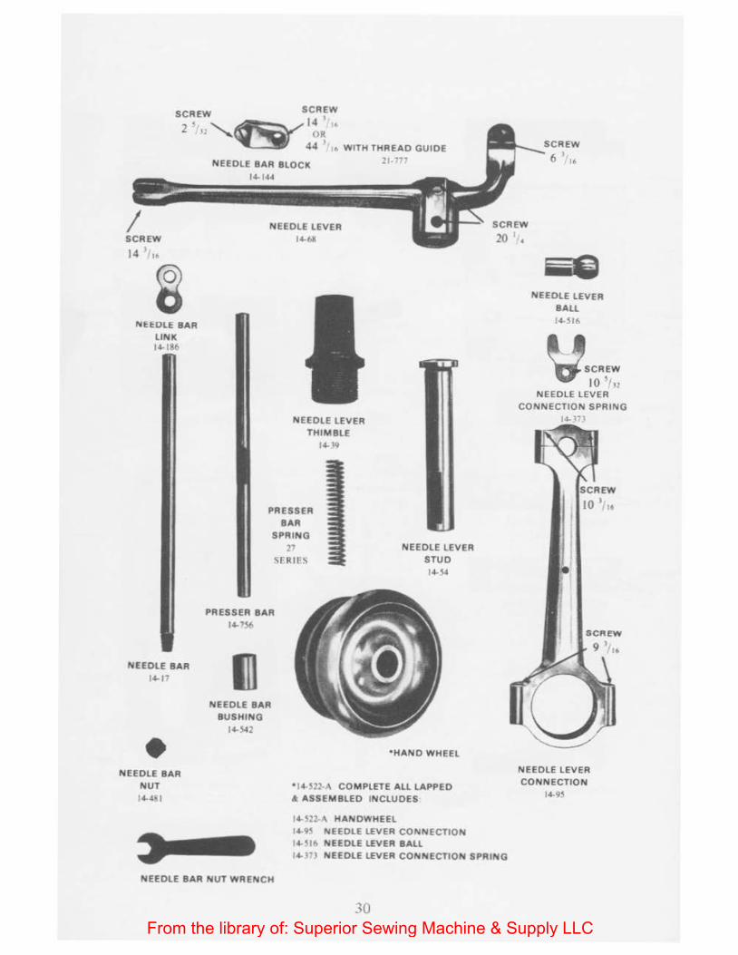
SCR~ SCR~W
2 ' ....._~14 ,.
I SCR~
14 ,.
NEEDLE BAR LINK 14- 186
NEEDLE BAR 14-17
• NEEDLE BAR NUT 14-4•1
' - ' OR 44
1 • WITH THREAD GUIDE
NEEDLE BAR BLOCK 14- 144
NEEDLE LEVER 14-(>11
NEEDLE LEVER THIMBLE
14-19
PRESSER BAR
SPRING 27
SfRIFS
PRESSER BAR 14-756
III NEEDLE BAR
BUSHING 14-.s-&2
21-77"
NEEDLE LEVER STUD 14-14
•HAND WHEEL
0 14- S22-A COM PLETE ALL LAPPED A ASSEMBLED INCLUDES
I 4- S22-A HANDWHEEL I4 9S NEEDLE LEVER CONNECTION 14- llh NEEDLE LEVER BALL
SCREW
20
' G NEEDLE LEVER
BALL 14-SI6
v.'"'. 10 ' 1•: NEEDLE LEVER
CONNECTION SPRING
NEEDLE LEVER CONNECTION
14-9S
14- 1"1 NEEDLE LEVER CONNECTION SPRING
NEEDLE BAR NUT WRENCH
30 From the library of: Superior Sewing Machine & Supply LLC
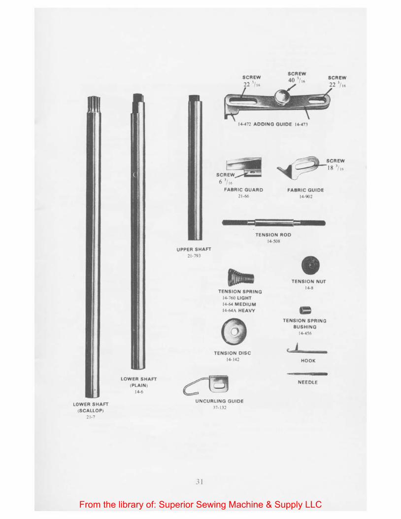
LOWER SHAFT (SCALLOP)
21-7
LOWER SHAFT (PlAIN)
14-6
UPPER SHAFT 21-791
SCREW 22 ,, ,.
14-472 ADDING GUIDE 14-473
SCR~ 6 >. ,.
FABRIC GUARD 21-66
,;~SCREW . .- l
~ - 18 '"
FABRIC GUIDE 14-902
TENSION ROO 14-S08
TENSION SPRING 14-760 LIGHT 14-64 MEDIUM l4-64A HEAVY
TENSION DISC 14-142
TENSION NUT 14-8
TENSION SPRING BUSHING
I4-4S6
( 1 HOOK
NEEDLE
UNCURLING GUIDE ~7-ll2
31
From the library of: Superior Sewing Machine & Supply LLC
L
FINGER PLATES 21-J2
SCREW
5 ) "
21-798
NEEDLE PLATE
14-213
NEEDLE PLATE WITH FINGER
FINGER PLATES 14-85 14-828
riHJN'f'M
STITCH CONTROLLER CARRIER! SPRING
' THREAD GUIDE 14-490
SCREW
~35'/,.
FINGER PLATE CLAMP 14-82
31
STITCH CONTROLLER CARRIER CAP
14-1.6
SCREW
SCR~W _......... 2 'In 13 "6-v ~
STITCH CONTROLLER CARRIER 14-90
J STITCH CONTROLLER
14-749
HEMMER I4-46~E
HOOK GAUGE 14-739
fS~cif\ Sue}
TWEEZERS
37-225-8
.)
From the library of: Superior Sewing Machine & Supply LLC
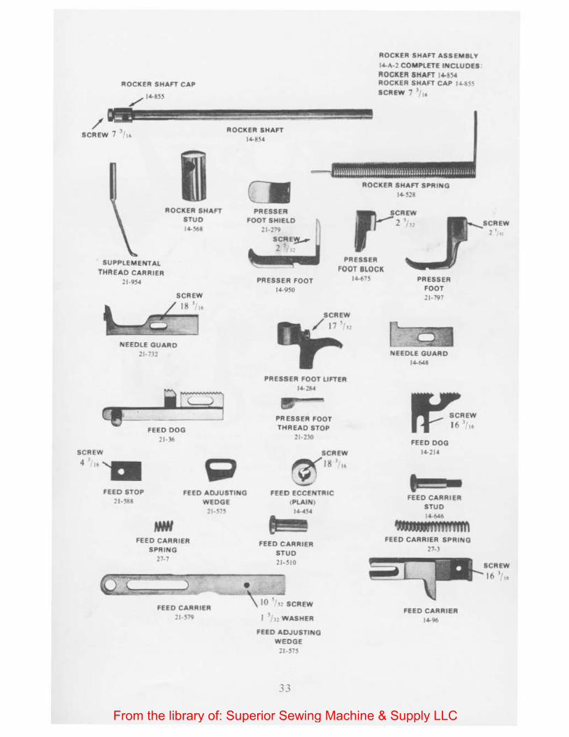
ROCKER SHAFT CAP
/ 14-8S5
/~ ~~~~~£~ ROCKER SHAFT SCREW 7
1/16 14-8$4
ROCKER SHAFT STUD 14-V.~
Cll PRESSER
FOOT SHIElD
ROCKER SHAFT ASSEMBLY
14-A·2 COM PLETE INCLUDES ROCKER SHAFT 1 4-~}4 ROCKER SHAFT CAP 14-~~S SCREW 1 J,"
ROCKER SHAFT SPRING 14-328
SUPPLEM ENTAL THREAD CARRIER
2 1-954
PRESSER FOOT BLOCK
SCREW
NEEDLE GUARD 21-' .12
FEED DOG 21-36
4 1 • •
FEED STOP 21-"-8
FEED ADJUSTING WEDGE 21·~.,s
FEED CARRIER SPRING
27-7
•
PRESSER FOOT 14-950
PRESSER FOOT LIFTER 14-284
• PRESSER FOOT THREAD STOP
21·230
SCREW
~181
1> '-..::.-'
FEED ECCENTRIC I PLAINI
I4-4S4
FEED CARRIER STUD 21-510
FEED CARRIER 21 S19
\ 10 ' " SCREW
I ' • WASHER
FEED ADJUSTING WEDGE
21-515
33
14-67$ PRESSER FOOT 21-797
NEEDLE GUARD 14-648
FEED DOG 14-214
t!!!!!!l• FEED CARRIER
STUD 14-646
.._mmnm FEED CARRIER SPRING
27-3
FEED CARRIER 14-96
SCREW
J6 I "
From the library of: Superior Sewing Machine & Supply LLC
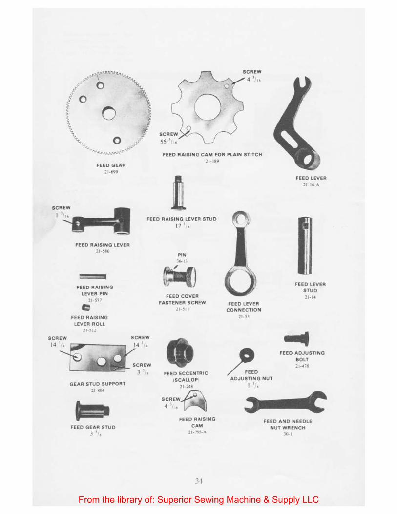
FEED GEAR 21 -699
0 FEED RAISING CAM FOR PLAIN STITCH
21-189
FEED LEVER 21· 1&-A
SCREW
1 FEED RAISING LEVER STUD
17 ', .
FEED RAISING LEVER 21-580
FEED RAISING
LEVER PIN 21-577
c FEED RAISING
LEVER ROLL 21 -512
SCREW SCREW
"~~::~ .._SJ'··a GEAR STUD SUPPORT
21-806
FEED GEAR STUD
J '1,
PIN \6-13
~ FEED COVER
FASTENER SCREW
21·511
FEED ECCENTRIC eSCALLOP I
21 · 248
SCREW~ 4 ll lt-~
FEED RAISING
CAM 21 -795-A
34
FEED LEVER CONNECTION
21 · 53
FEED LEVER
STUD 21- 14
FEED ADJUSTING BOLT 21-478
ADJUSTING NUT I I,.
FEED AND NEEDLE NUT WRENCH
30-1
From the library of: Superior Sewing Machine & Supply LLC
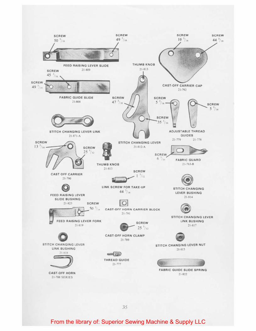
SCREW
JO lr,.
SCREW
FEED RAISING LEVER SLIDE
21-809
THUMB KNOB
21-813
45 "'· \
~I CAST-OFF CARRIER CAP
21-792
SCREW
FABRIC GUIDE SLIDE 21-1108
STITCH CHANGING LEVER LINK 21 -811-A
J) J"· ----7- SCREW
25 ' 'n
SCREW 47 J,,. SCREW
5 J,,.
ADJUSTABLE THREAD
GUIDES 21-779 21-178
STITCH CHANGING LEVER 21-HIZ-A
SCREW 1o b 6' /
I• FABRIC GUARD
THUMB KNOB
21-813
21-763-8
CAST OFF CARRIER 21-190
FEED RAISING LEVER
SLIDE BUSHING 21-823
0 STITCH CHANGING LEV ER
LINK BUSHING
21-XI~
J CAST-OFF HORN
21-788 SFRIES
SCREW
~0 1,1(1
SCREW
~~·.l
LINK SCREW FOR TAKE-UP 44 ,,,.
STITCH CHANGING LEVER BUSHING
21-814
CAST- OF F HORN CARRIER BLOCK
21-791
&_-SCREW
., 25 ', ,
CAST-OFF HORN CLAMP
21-789
THREAD GUIDE 21-777
35
STITCH CHANGING LEVER
LINK BUSHING 21-817
STITCH CHANGING LEVER NUT 21-815
FABRIC GUIDE SLIDE SPRING
21-822
From the library of: Superior Sewing Machine & Supply LLC
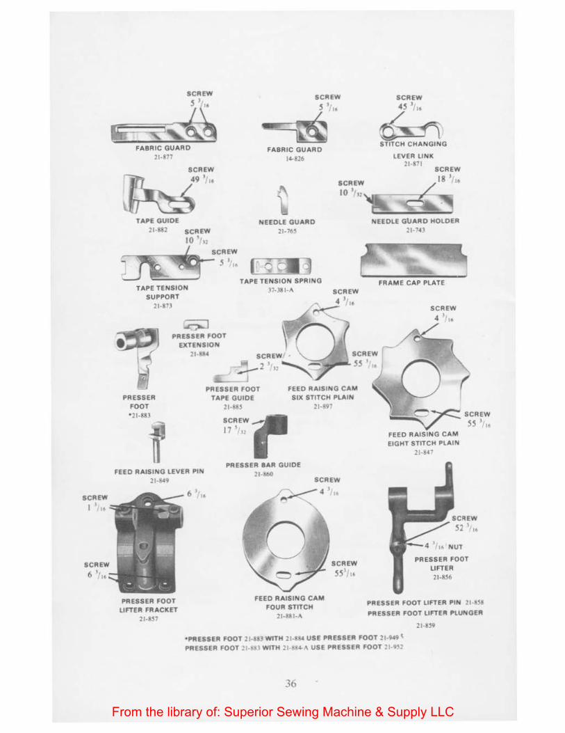
FABRIC GUARD 21-877
SCREW
SCREW
~" FABRIC GUARD
14-826
SCREW
~"~ STITCH CHANGING
lEVER LINK 21-871
SCREW
~··· SCREW 18 1/ t•
10 •-.,~e!~· ~~~, TAPE GUIDE
21-1182 SCREW
10 '',:
Lrticlct TAPE TENSION
SUPPORT 21-873
SCREW
5 •• ..
NEEDlE GUARD 21-76~
r o till TAPE TENSION SPRING
37-381-A
PRESSER FOOT EXTENSION
21-8U
PRESSER FOOT ' 21-883
FEED RAISING lEVER PIN
21-1>49
PRESSER FOOT liFTER FRACKET
21-R$1
6 ..
PRESSER FOOT FEED RAISING CAM SIX STITCH PlAIN
2H97 TAPE GUIDE
21- 118 $
SCREW
17 1112
PRESSER BAA GUIDE 21 1!60
SCREW
FEED RAISING CAM FOUR STTTCH
21·881-A
SCREW
551/ ,.
NEEDlE GUARD HOl DER
2J.7H
SCREW
4 l •
EIGHT STITCH PlAIN ::!1·84"'
SCREW
52 I 10
NUT
PRESSER FOOT liFTER
21·8S6
PRESSER FOOT liFTER PIN 2 1 -~18
PRESSER FOOT liFTER PlUNGER
21-U9
•PRESSER FOOT 21·8U WITH 21-81!-0 USE PRESSER FOOT 21·9•9 t PRESSER FOOT ' '·'D WTTH 21 -.-4-A USE PRESSER FOOT 21-9~2
36
From the library of: Superior Sewing Machine & Supply LLC

Index Section
Adding Attachment . . . . . . . . . . . . . . . . . . . . . . . . . . . . . . . . . . . . . . . . . . . . 21 Adjustable Thread Guides . . . . . . . . . . . . . . . . . . . . . . . . . . . . . . . . . . 23, 24 Alphabetical Index . . . . . . . . . . . . . . . . . . . . . . . . . . . . . . . Pages 21 thru 26 Cast Off Horn (Moving) ........................................ 25 Cast Off Horn (Stationary) . . . . . . . . . . . . . . . . . . . . . . . . . . . . . . . . . . . . . 26 Eight Stitch Shell . . . . . . . . . . . . . . . . . . . . . . . . . . . . . . . . . . . . . . . . . . . . . . 30 Eight Stitch Shell and Plain Crochet . . . . . . . . . . . . . . . . . . . . . . . . . . . . . 35 Fabric Edge Guide . . . . . . . . . . . . . . . . . . . . . . . . . . . . . . . . . . . . . . . . . . . . . 42 Fabric Guard . . . . . . . . . . . . . . . . . . . . . . . . . . . . . . . . . . . . . . . . . . . . . . . . . 29 Feed Gear and Feed Raising Cam Combinations . . . . . . . . . . . . . Page 28 Feed Raising Cam for Plain Stitch . . . . . . . . . . . . . . . . . . . . . . . . . . . . . . . 34 Feed (Plain Crochet) . . . . . . . . . . . . . . . . . . . . . . . . . . . . . . . . . . . . . . . . . . . 17 Feed (Shell Stitch) . . . . . . . . . . . . . . . . . .. . . . . . . . . . . . . . . . . . . . . . . . . . . . 18 Finger Plate . . . . . . . . . . . . . . . . . . . . . . . . . . . . . . . . . . . . . . . . . . . . . . . . . . 16 Four Stitch Shell . . . . . . . . . . . . . . . . . . . . . . . . . . . . . . . . . . . . . . . . . . . . . . 31 Four and Eight Stitch Shell . . . . . . . . . . . . . . . . . . . . . . . . . . . . . . . . . 32, 33 Hook . . . . . . . . . . . . . . . . . . . . . . . . . . . . . . . . . . . . . . . Page 26 & Section 14 Hook and Needle Combinations . . . . . . . . . . . . . . . . . . . . . . . . . . . . Page 27 Hook Carrier ................................................. 15 Hook Carrier Guide . . . . . . . . . . . . . . . . . . . . . . . . . . . . . . . . . . . . . . . . . . . 15 How to Order . . . . . . . . . . . . . . . . . . . . . . . . . . . . . . . . . . . . . . . . . . . . . Page I Latch Needle . . . . . . . . . . . . . . . . . . . . . . . . . . . . . . . . . . . . . . . . . . . . . . . . . . 14 Lubrication . . . . . . . . . . . . . . . . . . . . . . . . . . . . . . . . . . . . . . . . . . . . . . . . . . . I 0 Needle ...................................... Page 27 & Section 12 Needle Guard . . . . . . . . . . . . . . . . . . . . . . . . . . . . . . . . . . . . . . . . . . . . . . . . . 13 Needle Thread Takeup . . . . . . . . . . . . . . . . . . . . . . . . . . . . . . . . . . . . . . . . . 23 Parts Illustrated . . . . . . . . . . . . . . . . . . . . . . . . . . . . . . . . . . Pages 29 thru 36 Plain Crochet Stitch . . . . . . . . . . . . . . . . . . . . . . . . . . . . . . . . . . . . 34, 35, 39 Setting Up ................................................ Page 6 Six Stitch Shell . . . . . . . . . . . . . . . . . . . . . . . . . . . . . . . . . . . . . . . . . . . . . . . 36 Six Stitch Shell and Plain Crochet . . . . . . . . . . . . . . . . . . . . . . . . . . . . . . . 39 Special Feed Gears . . . . . . . . . . . . . . . . . . . . . . . . . . . . . . . . . . . . . . . . . . . . 40 Speed ......................................................... 9 Stitch Changing ............................................... 41 Stitch Controller . . . . . . . . . . . . . . . . . . . . . . . . . . . . . . . . . . . . . . . . . . . . . . 20 Supplemental Thread Carrier ................................... 19 Takeup . . . . . . . . . . . . . . . . . . . . . . . . . . . . . . . . . . . . . . . . . . . . . . . . . . . 23, 24 Taping . . . . . . . . . . . . . . . . . . . . . . . . . . . . . . . . . . . . . . Page 20 & Section 43 Tension . . . . . . . . . . . . . . . . . . . . . . . . . . . . . . . . . . . . . . . . . . . . . . . . . . . . . . 27 Threading . . . . . . . . . . . . . . . . . . . . . . . . . . . . . . . Pages 18, 19 & Section 22 Thread Stop . . . . . . . . . . . . . . . . . . . . . . . . . . . . . . . . . . . . . . . . . . . . . . . . . . 28 Three Stitch Shell . . . . . . . . . . . . . . . . . . . . . . . . . . . . . . . . . . . . . . . . . . . . . 37 Three and Six Stitch Shell . . . . . . . . . . . . . . . . . . . . . . . . . . . . . . . . . . . . . . 38
From the library of: Superior Sewing Machine & Supply LLC
THE
MERROW~ MACHINE COMPANY 28 Laurel StiHt Hartfonl, Cl 1111111 Ttl. (203) 522· 0215
From the library of: Superior Sewing Machine & Supply LLC