Embed Size (px)
Citation preview

CCFM Series Pump1
INSTRUCTION AND MAINTENANCE MANUAL:
FM SINgLE STAgE CLOSE COUpLED - STyLE pUMp
SANITARy CENTRIFUgAL pUMpS

Fristam Pumps2
DANGER: BEGIN ALL PUMP MAINTENANCE OPERATIONS BY DISCON-NECT- ING THE ENERGY SOURCE TO THE PUMP. OBSERVE ALL LOCK OUT/TAG OUT PROCEDURES AS OUTLINED BY ANSI Z244.1-1982 AND OSHA 1910.147 TO PREVENT ACCIDENTAL START UP AND
!
DESCRIPTION
This manual contains installation, operation, assembly, disassembly and repair instructions for the Fristam “CCFM” style single-stage pump. Please read this manual in its entirety before oper-ating the pump.
The motors used on “CCFM” style pumps are standard NEMA totally enclosed fan cooled (TEFC) motors. Replacement motors are readily available from local motor distributors. IEC motors are also available.
The open design of the impeller eases cleaning. The close clearance between the impeller and the housing and cover give effi ciencies similar to closed impellers.
Fristam pumps have an internal mechanical seal which allows the product pumped to cool, lubri-cate, and clean the front seal. Fristam does not recommend running this pump without product.
CCFM Series Pump3
TABLE OF CONTENTSDESCRIPTION ................................................................................................................................2TECHNICAL INFORMATION ..............................................................................................................4RECOMMENDED PREVENTIVE MAINTENANCE ............................................................................... 5-8SEAL REPLACEMENT ................................................................................................................ 9-11 PUMP HEAD DISASSEMBLY ................................................................................................. 9-10 PUMP HEAD ASSEMBLY ................................................................................................... 10-11CCFM SEAL ASSEMBLY DRAWING ..............................................................................................12PUMP SHAFT AND/OR MOTOR REPLACEMENT .......................................................................... 13-14FM CLOSE COUPLED ASSEMBLY ............................................................................................ 16-17TROUBLESHOOTING ......................................................................................................................18NOTICE OF TERMS, WARRANTY PROVISIONS INCLUDING DISCLAIMEERS,
CLAIMS AND LIMITATION OF LIABILITY ...................................................................................19

Fristam Pumps4
TECHNICAL INFORMATION
SPECIFICATIONS
Maximum Inlet Pressure ...............................................................................................1000 PSITemperature Range ............................................................................................... -40°F - 400°FNoise Level ...........................................................................................................60 - 85 dB(A)MATERIALS OF CONSTRUCTION
Primary Product Contact Components ..........................................................................AISI 316Casing Gasket ................................................................................................... Viton (standard) Also Available in .................................................................................................. EPDMSurface Finish for Product Contact Surfaces ....................................................32 Ra (standard)SHAFT SEALS
Mechanical Seal Type .................................................................................. Double MechanicalWater Flush Pressure ....................................................................................................... 1-2 PSIWater Consumption (seal fl ush) ........................................................................................12 gphPrimary Stationary Seal Ring Material ...............................................................Silicon CarbidePrimary Rotating Seal Ring Material ..................................................................Silicon CarbideSeal O-ring Material ......................................................................................... Viton (standard) Also Available in ...................................BUNA-N, EPDM, other available upon requestMOTOR INFORMATION
Uses standard NEMA rigid base motors. Options include washdown, high effi ciency, premium effi ciency, explosion proof, chemical duty and IEC.
Voltage and Frequency3 phase, 50 Hz, 208-220/330-415 VAC .................... 2900 RPM3 phase, 60 Hz, 208-230/460 VAC ........................... 3500 RPM3 phase, 60 Hz, 575 VAC .......................................... 3500 RPM
Motor ShaftAxail and Radial play ≤ 0.002"RECOMMENDED TORQUE VALUES
Impeller nut 40 ft.-lbsSeal retaining ring bolts 5 ft.-lbsSeal driver set screw 10 in.-lbs.Housing bolt 50 ft.-lbs.Cover nut 105 ft.-lbs.IMPELLER GAP (IMPELLER TO HOUSING MEASUREMENT)single or multistage pumps .030” - .040” (.8 - 1.0 mm)
CCFM Series Pump5
Recommended PReventive maintenance
Recommended Seal maintenance
Visually inspect mechancial seal daily for leakage. Replace mechanical seal annually under normal duty. Replace mechanical seal as often as required under heavy duty.elaStomeR inSPection Inspect all elastomers when performing pump maintenance. We recommend replacing elastomers (o-rings and gaskets) during seal, pump shaft and/or motor replacement. If the impeller nut gas-ket fails, the threaded hole on the impeller nut and the threads on the end of the shaft will need to be cleaned. A wire brush is recommended for cleaning these threads.lubRication RecommendationS:Use a food grade lubricant on o-rings and gaskets unless otherwise specified. If using EPDM o-rings or gaskets, an oil-based lubricant can’t be used.motoR lubRication RecommendationS:Use a high grade ball and roller bearing grease. Recommendations for standard service condi-tions include Shell Dolium R or Chevron SRI. (See Tables 1-3 for more details.)
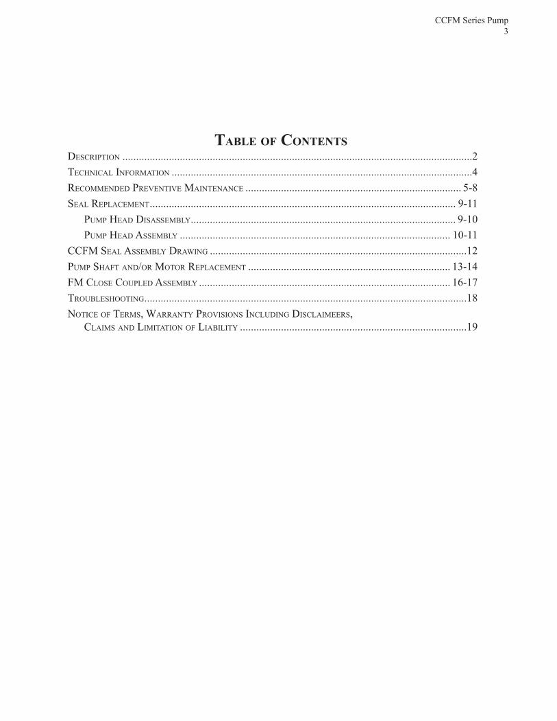
Table 1: Motor lubrication intervals for standard service conditions:
FRame Size motoR SPeed nema/(iec) 3500 RPm Over 210 to 280 (132 to 180) inclusive 9,500 hours
For severe service conditions, multiply interval hours by .5 For extreme service conditions, multiply interval hours by .1
Table 2: Service condition definitions:
SeRvice maximum ambient atmoSPheRic condition temPeRatuRe contamination
Standard 104°F (40°C) Clean, little corrosion. Severe 122°F (50°C) Moderate dirt, corrosion. Extreme > 122°F (> 50°C) Severe, dirt, abrasive dust, corrosion.
Table 3: Volume of grease to be added:
Frame Size Grease Volume NEMA/(IEC) IN.3 TSP Over 210 to 280 (132 to 180) inclusive 1.2 3.9

Fristam Pumps6
INSTALLATIONUNPACKING
Before accepting a pump from a carrier, visually inspect the packaging for any damage.
Check the contents and all wrapping when unpacking the pump. Carefully inspect for any dam-age that may have occurred during shipping. Immediately report any damage to the carrier. Remove the coupling guard and protective cover from pump outlet. Place your ear near the pump outlet and turn the shaft by hand, a small amount of noise from the seals is normal. Metal-to-met-al contact will be very noticeable. If you have metal-to-metal contact, shipping damage is likely. Leave the protective caps over the pump inlet and outlet connections until you are ready to install the pump.INSTALLING
Prior to actually installing the pump, ensure that:
• the pump will be readily accessible for maintenance, inspection and cleaning.• adequate ventilation is provided for motor cooling.• the drive and motor type is suitable for the environment where it is to be operated. Pumps
intended for use in hazardous environments e.g., explosive, corrosive, etc., must use a motor and drive with the appropriate enclosure characteristics. Failure to use an appropriate motor type may result in serious damage and/or injury.
We ship our pumps fully assembled.DESCRIPTION
The Fristam “CCFM” single- stage pump has operating characteristics similar to standard impel-ler centrifugal pumps. The unit is NOT self-priming. It requires a fl ooded suction.MAXIMUM OPERATING CONDITIONS FOR CCFM SERIES PUMPS
System Pressure: 1000 PSI (69 Bar)Capacity: 300 gpm (68 m /Hr.)Discharge Pressure: 1275 psi (88 Bar)Power: 25 HPPIPING GUIDELINES
This section describes good piping practices to obtain maximum effi ciency and service life from your pump.
Maximum performance and trouble-free opera-tion require adherence to good piping practices.
• Ensuring proper piping support and alignment at both the suction inlet and discharge outlet can help prevent serious damage to the pump housing (Figure 1).
1265000331 Rev-
Figure 1

CCFM Series Pump7
• Avoid abrupt transitions in the piping system (Figure 2).
• Avoid throttling valves in the suction piping.• Keep suction lines as short and direct as possible.• Ensure that the NPSH available in the system is greater
than NPSH required by the pump.
• Avoid sump areas where sediments may collect (Figure 3).
• Avoid the formation of air pockets in the piping (Figure 4).• Avoid abrupt closure of shut-off valves, this may cause hydraulic shock which can cause severe damage to the pump and system.
• Avoid elbows in the suction line if possible. When necessary they should be located 5 pipe diameters away from the pump inlet, and have a bend radius greater than 2 pipe diameters (Figure 5).
Figure 2
Figure 3
Figure 4
Figure 5

Fristam Pumps8
ELECTRICAL INSTALLATION
We use standard duty TEFC motors unless otherwise specifi ed. Many motor options are available: washdown, fl ameproof, explosion proof, hostile duty or chemical duty.
Have an electrician connect the motor using sound electrical practices. Provide adequate protection. Pumps fi tted with mechanical seals must not run dry, not even momentarily. Determine the direction of rotation by watching the motor fan, which must turn clockwise.
The motor selected should meet the requirements of the specifi ed operating conditions. A change in conditions (for example, higher viscosity, higher specifi c gravity, lower head losses) can overload the motor. When changing operating conditions or whenever there is any doubt, please contact Fristam Pumps, Inc., for technical assistance.PUMP OPERATIONS
START-UP INSTRUCTIONS
• Remove any foreign matter that may have entered the pump.• Do not use the pump to fl ush the system!
Check pump for proper rotation as indicated on the pump. Proper motor direction is clockwise when looking at the fan end of the motor. (NOTE: When checking the direction of rotation, the pump must be full of liquid.)
• Never run the pump dry, even momentarily. Seal damage can result.SHUT-DOWN INSTRUCTIONS
• Shut off the power supply to the pump.• Close the shut-off valves in the suction and discharge piping.• Drain and clean the pump as required.• Protect the pump against dust, heat, moisture and impact damage.
INSTALLATION OF SEAL FLUSH FOR DOUBLE MECHANICAL SEAL
Set up the seal fl ush for the double mechanical seal as shown in (Figure 7). Use only about 12 gallons per hour of water at a pressure of 1-2 PSI.
Pipe the exit side of the water fl ush with 2-5 feet physical height of tubing. This ensures that some water is always in the center seal and the seal never runs dry.
It is desirable to have the fl ush water on the outlet side visible. This allows an easy check to see that the fl ush water is on and also if the seal is functioning properly. In a malfunctioning seal the fl ush water will disappear, become discolored, or show an unusual in-crease in fl ow. If these conditions exist, check the seal and replace if necessary.
2.5 FT.
COOLING WATER IN
WATER PIPE CONNECTIONS
TO DRAIN
THROTTLE VALVE TO 12 gal/hr (1-2 psi)
1/8" N.P.T.
1265000333 Rev-
Figure 7

CCFM Series Pump9
SEAL REPLACEMENTBegin all pump maintenance by disconnecting the energy source to the pump. Observe all lock out/tag out procedures as outlined by ANSI Z244.1-1982 and OSHA 1910.147 to prevent accidental start up and injury.
REQUIRED TOOLS
One pair of pliers or channel locks One set of feeler gaugesOne 7/16” wrench One 3/4” wrench One 15/16” socket wrench One 1” wrenchSoft-faced hammerFM wrench - 1 1/2" open end (provided by Fristam)Optional: One set of impeller pullers (commonly available as tack pullers)
PUMP HEAD DISASSEMBLY
Note: the reference numbers listed in the text (#) refer to the assembly drawing on pages 18 & 19.
Disconnect the suction and discharge piping. Drain all fl uids from the pump.
a) Loosen the cover nuts (37) with the 1" wrench. Remove the cover nuts, fl at washers (36) (if supplied), cover (23) and cover gasket (22).
b) Loosen and remove the four guard screws (27). c) Remove the seal guard (28).d) Using the FM wrench on the shaft, turn the impeller nut (21) with the 15/16” socket wrench
counter-clockwise until it threads off the pump shaft. e) Remove the impeller nut and impeller gasket (19). f) Remove impeller key (35) from the pump shaft.g) Remove the impeller (20) by pulling the impeller toward you. (If the impeller is diffi cult to
pull off the shaft, wedge the tack pullers between the pump housing and the impeller and pry the impeller off the shaft.)
h) Remove the rotating seal assembly which includes: the impeller gasket (19), seal driver (18), rotating seal (15), seal spring (16) and rotating seal o-ring (17). To remove this assembly from the shaft, place the tack pullers on both sides of the assembly and pull toward the end of the pump shaft.
i) Remove the o-ring (14) and stainless gapping spacer (13) from the shaft. IMPORTANT: This gapping spacer is unique to this pump as it ensures the correct gap for the impellers as installed at the factory (Figure 10, page 15). Do not discard. If you are replacing the pump shaft/motor on your CCFM pump, please contact the factory for proper gapping procedure.
!

Fristam Pumps10
j) Remove the two water pipes (10) (if supplied) on either side of the pump housing using pliers or channel locks.
k) Next remove the four pump housing bolts (26) and lock washers (24) which attach the pump housing (33) to the fl ange adapter (2) using the 3/4” wrench.
l) Slide the pump housing off the end of the pump shaft.m) Place the pump housing on its hub. n) Remove the stationary seal (12) by placing your fi ngers on the ID of the stationary seal and
pulling it toward the front of the pump housing. The stationary seal o-ring (11) should come out with the stationary seal. Discard after removal.
o) Turn the housing over and place it on the housing studs. Loosen and remove the four retain-ing ring bolts (8) on the pump housing with the 7/16” wrench. Remove the retaining ring (30), stationary water seal (31) and fl at gasket (32) from the pump housing.
p) Now remove the rotating water fl ush components for the pump shaft, which include: the rotat-ing water seal ring (7), the rotating water seal o-ring (6), the water seal spring (5), and the water seal drive ring (4). The water seal driver (3) may be left on the pump shaft.
You are now ready to install the new seal and reassemble the pump head.PUMP HEAD ASSEMBLY
Note: when installing the new seal components make sure that you use all of the components supplied with the replacement seal kit. Using some of the old components may reduce seal life.
You are now ready to install the new seals into the pump (Figure 9, page 12).
a) Start the seal assembly by sliding the new water seal drive ring (4) onto the pump shaft with the shorter tabs facing the water seal driver (3). Align the tabs with the slots in the seal driver.
b) Slide the new water seal spring (5) onto the pump shaft and position it against the water seal drive ring.
c) Lubricate the new water seal o-ring (6) with a food grade lubricant. Place the o-ring inside the rotating water seal ring (7) and slide the assembly onto the pump shaft. Align the tabs in the water seal drive ring with the slots in the water seal ring.
d) With the pump housing still sitting on the housing studs, place the new stationary seal fl at gasket (32) and stationary water seal (31) into the pump housing.
e) Replace the retaining ring (30) onto the hub of the pump housing and install the four retaining ring bolts (8). Tighten with the 7/16” wrench to the proper torque (see page 4).
f) Turn the pump housing over and place it on its hub. Generously lubricate the outside station-ary seal o-ring (11) with a food grade lubricant and place it onto the stationary seal (12). Place the stationary seal and o-ring into the bottom of the pump housing. Align the notch in the stationary seal with the pin in the pump housing and press the stationary seal into the pump housing until it snaps into place.
g) Carefully slide the pump housing over the pump shaft and push it against the fl ange adapter (2) ensuring that the stationary seals (which are mounted in the pump housing) do not contact

CCFM Series Pump11
the pump shaft. Note: the stationary seals may be damaged if they make hard contact with the pump shaft.
h) Install the four pump housing bolts (25) with lock washers (24). Tighten them with the 3/4” wrench to the proper torque, see page 4.
i) Lubricate the new seal driver o-ring (14) with a food grade lubricant and place it on the stain-less gapping spacer. Slide the gapping spacer and o-ring on to the pump shaft. (Note: it is important, to use the same gapping spacer that was removed, as this is unique to your pump. The gap behind the impeller is listed on page 4.)
j) Now install the new rotating seal assembly which includes: the impeller gasket (19), seal driver (18), rotating seal (15), seal spring (16) and rotating seal o-ring (17). First install the seal spring into the rotating seal between the pins and the front seal face. Next install the rotat-ing seal o-ring into the rotating seal. Align the pins on the rotating seal with the grooves on the seal driver and press the two components together. Lubricate the impeller gasket (if it is not EPDM) with a food grade lubricant and place it into the groove on the seal driver. Slide the rotating seal assembly onto the pump shaft so the face of the rotating seal meets the face of the stationary seal.
k) Place the impeller key (25) into the shaft keyway and slide the impeller (20) onto the pump shaft.
l) Locate the new impeller nut gasket (19) and lubricate it (if it is not EPDM) with a food grade lubricant and place it onto the impel-ler nut (21). Thread the impeller nut with gasket onto the pump shaft. Hand tighten the impeller nut for now.
m) Place the new cover gasket (22) into the groove on the pump cover and install them onto the pump housing. Thread the cover nuts (37) and fl at washers (36) onto the housing studs. With a cross-tightening pattern, tighten the cover nuts to the proper torque, see page 4. (Figure 8).
n) Place the 1 1/2" wrench on the pump shaft, to keep the shaft from rotating while tightening the impeller nut with an 15/16” socket wrench. Tighten the impeller nut to the proper torque, see page 4.
o) Remove the wrench and rotate the pump shaft to make sure that the impeller moves freely. If it does not, recheck your assembly to make sure that gaskets aren’t pinched and everything is seated properly.
Replace the seal guard and guard screws.
Figure 8

Fristam Pumps12
Figure 9: CCFM Seal Assembly
13 32 31 7 6 5 4 3 29
19 18 14 17 16 13 15 12 11 32 31 7 6 5 4 29 3
DESCRIPTION19. Impeller gasket18. Seal driver14. Seal driver o-ring17. Rotating seal o-ring16. Seal spring13. Gapping spacer15. Rotating seal12. Stationary seal11. Stationary seal o-ring
32. Flat gasket31. Stationary water seal 7. Rotating water seal ring 6. Rotating water seal o-ring 5. Water seal spring 4. Water seal drive ring29. Set screw 3. Water seal driver
19 18 17 14 16 15 12 11
13 32 31 7 6 5 4 3 29

CCFM Series Pump13
PUMP SHAFT AND/OR MOTOR REPLACEMENTBegin all pump maintenance by disconnecting the energy source to the pump. Observe all lock out/tag out procedures as outlined by ANSI Z244.1-1982 and OSHA 1910.147 to prevent accidental start up and injury.REQUIRED TOOLS
One 1/2” wrenchOne 3/32” Allen wrenchOne 15/16” wrenchOne 3/16” Allen wrenchSnap ring pliers One 5 lb. soft-faced hammerOne spanner wrenchScrewdriverOne pair of pliers or channel locksShimsShaft alignment toolTorchArbor press PUMP DISASSEMBLY
Disassemble the pump head as described on pages 9-10.
a) Loosen the four fl ange bolts (24) and washers (25) with the 3/4” wrench.
b) Remove the fl ange support from the motor.
The CCFM motor and pump shaft are one unit. PUMP ASSEMBLY
Place the fl ange support (2) on the new motor unit (1), replace the fl ange bolts (24) and washers (25) and tighten to the appropriate torque (see page 4).
Finish the pump assembly as described on pages 10-11.
!

Fristam Pumps14
CHECKING THE IMPELLER GAP
If you have changed the motor, the pump will need gapping.
In order to check the gap, place the gapping spacer (26), seal driver (31), impeller key (56), im-peller gaskets (32) impeller (33) and impellers with backplates (37) and fi nally the impeller nut (38) with the impeller nut gasket (32) in place. Tighten the impeller nut to the proper torque, see page 5.
The gap is measured between the impeller (37) and pump housing (54) using feeler gauges. (NOTE: Due to polishing and balancing the impeller, the gap behind each impeller blade may vary. The gap should be checked behind each blade and the smallest value should be used as your gap setting.) The correct gap dimensions are listed on page 4
If the gap isn't correct please contact Fristam Pumps for a new gapping spacer (26).

CCFM Series Pump15
Figure 10: Gap Set At Factory
DIMENSION "A" = 1 ±0.3mm
1265000332 Rev-
A
PRESET AT FACTORY

Fristam Pumps16
CLOSE COUPLED FM ASSEMBLY EXPLODED VIEW
1. Motor2. Flange adapter3. Water seal driver4. Water seal drive ring5. Water seal spring6. Rotating water seal o-ring7. Rotating water seal ring8. Retaining ring bolt9. Housing pin10.Water pipe11. Stationary seal o-ring12. Stationary seal13. Gapping spacer14. Seal driver o-ring
15. Rotating seal 16. Seal spring17.Rotating seal o-ring18. Seal driver19. Impeller gasket20. Impeller (no backplate)21. Impeller nut22. Cover gasket23. Pump cover24. Lock washer25. Flange bolt26. Housing bolt27. Guard screw28. Seal guard29. Set screw
26

CCFM Series Pump17
30. Retaining ring31. Stationary water seal32. Flat gasket33. Pump housing34. Housing stud35. Impeller key36. Flat washer37. Cover nut

Fristam Pumps18
TROUBLE SHOOTINGFristam pumps are relatively maintenance free, however, in the event that a problem does arise, the troubleshooting chart below should help you with most of your pump related problems. If a motor problem arises please contact your local motor repair representative.
This troubleshooting chart has been prepared assuming that the pump installed is suitable for the application. Symptoms of cavitation can result when a pump is not properly applied. Examples of these symptoms are noisy operation, insuffi cient discharge, and vibration. If these conditions are present, check the system and re-evaluate the application. If you need assistance, contact Fristam Pumps at 800-841-5001 or 608-831-5001.
PROBEM
Discharge pressure insuffi -cient
Capacity insuffi cient
Drive power too high
Noisy operation
CAUSE
Direction of rotation incorrect
Motor speed too lowImpeller diameter too small
Direction of rotation incorrect
Discharge pressure too high
Product viscosityAir leaks on suction side
Product viscosity too highDischarge pressure insuffi -cientImpeller diameter too large
Cavitation due to insuffi cient NPSH
Impeller to housing contact
Bearing failure
SOLUTION
Reverse electrical phases to motor
Reverse electrical phases to motorCheck for partly closed valves or blockages. If not, check pipework design
Replace pipework gaskets and/or mechanical seal
Throttle pump dischargeCheck order and consult Fris-tam
Frictional resistance in pipe-work too high or suction ves-sel level too lowReassembly pump or correct poor pipework installationReplace motor bearingsConsult Fristam

CCFM Series Pump19
NOTICE OF TERMS, WARRANTY PROVISIONS INCLUDING DISCLAIMERS, CLAIMS AND
LIMITATION OF LIABILITYPrices and all terms and conditions of sale are established in current price sheets and are subject to change without notice. All orders are subject to acceptance by Fristam Pumps USA Limited Partnership.
Each Fristam Pumps item is warranted to be free from manufacturing defects for a period of one (1) year from the date of shipment, providing it has been used as recommended and in ac-cordance with recognized piping practice, and providing it has not been worn out due to severe service, such as encountered under extremely corrosive or abrasive conditions.
THIS WARRANTY IS EXPRESSLY IN LIEU OF ANY OTHER WARRANTIES EX-PRESSED OR IMPLIED, INCLUDING BUT NOT LIMITED TO, ANY IMPLIED WAR-RANTY OF MERCHANTABILITY OR FITNESS FOR PARTICULAR PURPOSE. ALL OTHER WARRANTIES WHATSOEVER, EXPRESSED OR IMPLIED BY LAW OR OTHERWISE, ARE HEREBY EXCLUDED.
All claims must be in writing and mailed or delivered by purchaser within thirty (30) days after purchaser learns the facts upon which such claim is based. Any claim not made in writing and within the time period specifi ed above shall be deemed waived.
PURCHASER’S SOLE AND EXCLUSIVE REMEDY AND FRISTAM PUMPS, MAXI-MUM LIABILITY FOR CLAIMS ARISING HEREUNDER OR FOR NEGLIGENCE FOR ANY AND ALL LOSSES AND DAMAGES RESULTING FROM ANY CAUSE SHALL BE EITHER THE REPAIR OR REPLACEMENT OF DEFECTIVE ITEMS OR, AT FRISTAM PUMPS’ OPTION, THE REFUND OF THE PURCHASE PRICE FOR SUCH ITEMS. IN NO EVENT, INCLUDING IN THE CASE OF A CLAIM FOR NEG-LIGENCE, SHALL FRISTAM PUMPS BE LIABLE FOR INCIDENTAL OR CONSE-QUENTIAL DAMAGES, INCLUDING LOSS OF PROFITS.
No person, including any representative, employee or agent of Fristam Pumps, is authorized to assume on behalf of Fristam Pumps any liability or responsibility in addition to or different from that described in this provision. Any and all representations, promises, warranties or statements that are in addition to or different from the terms of this provision are of no force or effect.
If any provision of this Notice is held to be invalid, such provision shall be severed and the re-maining provisions shall continue to be in force.

Fristam Pumps20
2410 Parview Road • Middleton, WI 53562-2524 1-800-841-5001 • 608-831-5001
www.fristam.comEmail: [email protected]
© Copyright 20011 - Fristam Pumps USA Limited PartnershipDrawing # 1250000013 Rev A Updated 6/3/2011Part # 1050000054Visit www.fristam.com for a current list of literature.