Embed Size (px)
Citation preview

IMPORTANTPlease make certain that the person who is to use this equipment carefully reads and understands these instructions before starting operations.
Instructionmanual
Double Insulated Routers
MODEL 7518Consisting of:
MODEL 75182 MotorMODEL 75361 Base
MODEL 7519Consisting of:
MODEL 75192 MotorMODEL 75361 Base
®

Some dust created by power sanding, sawing, grinding, drilling, and other construction activities contains chemicals
known (to the State of California) to cause cancer, birth defects or other reproductive harm. Some examples of these chemicals are:
• lead from lead-based paints
• crystalline silica from bricks and cement and other masonry products
• arsenic and chromium from chemically-treated lumber
Your risk from these exposures varies, depending on how often you do this type of work. To reduce your exposure to these chemicals: work in a well ventilated area, and work with approved safety equipment, al ways wear NIOSH/OSHA approved, properly fit ting face mask or res pi ra tor when us ing such tools.
CALIFORNIA PROPOSITION 65
It is important for you to read and understand this manual. The information it contains relates to protecting YOUR SAFETY and PREVENTING PROBLEMS. The symbols below are used to help you recognize this information.
SAFETY GUIDELINES - DEFINITIONS
indicates an imminently hazardous situation which, if not avoided, will result in death or serious injury.
indicates a potentially hazardous situation which, if not avoided,could result in death or serious injury.
indicates a potentially haz ard ous situation which, if not avoided,may result in minor or mod er ate injury.
used without the safety alert symbol indicates potentially hazardous situation which, if not avoided, may result in property damage.

Read all instructions. Failure to follow all instructions listed below may result in electric
shock, fire and/or serious injury. The term "power tool" in all of the warnings listed below refers to your mains-operated (corded) power tool or battery-operated (cordless) power tool.
SAVE THESE INSTRUCTIONS1) Work area safety
a) Keep work area clean and well lit. Cluttered or dark areas inviteaccidents.
b) Do not operate power tools in explosive atmospheres, such as inthe presence of flammable liquids, gases or dust. Power tools createsparks which may ignite the dust or fumes.
c) Keep children and bystanders away while operating a power tool.Distractions can cause you to lose control.
2) Electrical safetya) Power tool plugs must match the outlet. Never modify the plug in
any way. Do not use any adapter plugs with earthed (grounded)power tools. Unmodified plugs and matching outlets will reduce risk ofelectric shock.
b) Avoid body contact with earthed or grounded surfaces such aspipes, radiators, ranges and refrigerators. There is an increased risk ofelectric shock if your body is earthed or grounded.
c) Do not expose power tools to rain or wet conditions. Water entering apower tool will increase the risk of electric shock.
d) Do not abuse the cord. Never use the cord for carrying, pulling orunplugging the power tool. Keep cord away from heat, oil, sharpedges or moving parts. Damaged or entangled cords increase the riskof electric shock.
e) When operating a power tool outdoors, use an extension cordsuitable for outdoor use. Use of a cord suitable for outdoor use reducesthe risk of electric shock.
3) Personal safetya) Stay alert, watch what you are doing and use common sense when
operating a power tool. Do not use a power tool while you are tiredor under the influence of drugs, alcohol or medication. A moment ofinattention while operating power tools may result in serious personalinjury.
b) Use safety equipment. Always wear eye protection. Safety equipmentsuch as dust mask, non-skid safety shoes, hard hat, or hearing protectionused for appropriate conditions will reduce personal injuries.
c) Avoid accidental starting. Ensure the switch is in the off-positionbefore plugging in. Carrying power tools with your finger on the switchor plugging in power tools that have the switch on invites accidents.
d) Remove any adjusting key or wrench before turning the power toolon. A wrench or a key left attached to a rotating part of the power tool
GENERAL SAFETY RULES

may result in personal injury.e) Do not overreach. Keep proper footing and balance at all times. This
enables better control of the power tool in unexpected situations.f) Dress properly. Do not wear loose clothing or jewelry. Keep your
hair, clothing and gloves away from moving parts. Loose clothes, jewelry or long hair can be caught in moving parts.
g) If devices are provided for the connection of dust extraction andcollection facilities, ensure these are connected and properly used. Use of these devices can reduce dust-related hazards.
4) Power tool use and carea) Do not force the power tool. Use the correct power tool for your
application. The correct power tool will do the job better and safer atthe rate for which it was designed.
b) Do not use the power tool if the switch does not turn it on and off.Any power tool that cannot be controlled with the switch is dangerousand must be repaired.
c) Disconnect the plug from the power source before making anyadjustments, changing accessories, or storing power tools. Suchpreventive safety measures reduce the risk of starting the power toolaccidentally.
d) Store idle power tools out of the reach of children and do not allowpersons unfamiliar with the power tool or these instructions tooperate the power tool. Power tools are dangerous in the hands ofuntrained users.
e) Maintain power tools. Check for misalignment or binding of movingparts, breakage of parts and any other condition that may affect thepower tools operation. If damaged, have the power tool repairedbefore use. Many accidents are caused by poorly maintained powertools.
f) Keep cutting tools sharp and clean. Properly maintained cutting toolswith sharp cutting edges are less likely to bind and are easier to control.
g) Use the power tool, accessories and tool bits etc., in accordancewith these instructions and in the manner intended for the particulartype of power tool, taking into account the working conditionsand the work to be performed. Use of the power tool for operationsdifferent from those intended could result in a hazardous situation.
5) Servicea) Have your power tool serviced by a qualified repair person using
only identical replacement parts. This will ensure that the safety of thepower tool is maintained.
GENERAL SAFETY RULES continued

1. HOLD POWER TOOL BY INSULATED GRIPPING SURFACES WHENPERFORMING AN OPERATION WHERE THE CUTTING TOOL MAY CONTACT HIDDEN WIRING OR ITS OWN CORD. Contact with a "live" wire will make exposed metal parts of the tool "live" and shock the operator.
2. USE CLAMPS OR OTHER PRACTICAL WAY TO SECURE AND SUPPORTTHE WORKPIECE TO A STABLE PLATFORM. Holding the work by hand or against your body is unstable and may lead to loss of control.
3. DISCONNECT TOOL FROM POWER SOURCE before making adjustmentsor changing bits.
4. TIGHTEN COLLET NUT securely to prevent the bit from slipping.5. USE A CLAMP or some other device to hold the workpiece rigidly in position.
and clear the path of the tool of obstructions.6. PROVIDE CLEARANCE under workpiece for router bit when through-cutting.7. CHECK TO SEE THAT THE CORD will not “hang up” during routing operation.8. CLEAR THE ROUTER BIT AREA before starting motor.9. MAINTAIN FIRM GRIP on router to resist starting torque.10. KEEP HANDS CLEAR OF BIT when motor is running to prevent personal injury.11. KEEP CUTTING PRESSURE CONSTANT. Do not overload motor.12. LET THE MOTOR COME TO A COMPLETE STOP before putting the tool down.13. NEVER TOUCH router bits after use. They may be extremely hot.14. NEVER TIGHTEN COLLET NUT without a bit.15. DO NOT USE ROUTER BITS with a diameter in excess of 2-1/2" at RPM above
13,000. Router bits up to 3-1/2" in diameter can be used when speed control isset for 13,000 RPM or less.
16. ALWAYS KEEP CHIP SHIELD clean and in place.17. AVOID “CLIMB-CUTTING” (see “Using The Router” section in this manual).
“Climb-cutting” increases the chance for loss of control resulting in possiblepersonal injury.
18. DO NOT HAND-HOLD THE ROUTER IN AN UPSIDE-DOWN OR HORIZONTAL POSITION. The motor can separate from the base if not properly attachedaccording to the instructions.
19. Wear eye and hearing protection. Always use safety glasses. Everydayeyeglasses are NOT safety glasses. USE CERTIFIED SAFETY EQUIPMENT.Eye protection equipment should comply with ANSI Z87.1 standards. Hearingequipment should comply with ANSI S3.19 standards.
20. Use of this tool can generate and disburse dust or other airborne particles, including wood dust, crystalline silica dust and asbestosdust. Direct particles away from face and body. Always operate tool in wellventilated area and provide for proper dust removal. Use dust collection systemwherever possible. Exposure to the dust may cause serious and permanentrespiratory or other injury, including silicosis (a serious lung disease), cancer,and death. Avoid breathing the dust, and avoid prolonged contact with dust.Allowing dust to get into your mouth or eyes, or lay on your skin may promoteabsorption of harmful material. Always use properly fitting NIOSH/OSHAapproved respiratory protection appropriate for the dust exposure, and washexposed areas with soap and water.
ADDITIONAL SPECIFIC SAFETY RULES

SYMBOL DEFINITIONV ........................................ voltsA ........................................ amperesHz ...................................... hertzW ....................................... wattskW ..................................... kilowattsF ........................................ faradsµF ...................................... microfaradsl .......................................... litresg ........................................ gramskg ....................................... kilogramsbar ..................................... barsPa ...................................... pascalsh ........................................ hours min ..................................... minutess ......................................... secondsn0 ....................................... no-load speed.../min or …min-1 .............. Revolutions or reciprocations per minute
or d.c. .................... direct current
or a.c. ....................... alternating current
2 ............................ two-phase alternating current
2N ........................... two-phase alternating current with neutral
3 .............................. three-phase alternating current
3N ............................ three-phase alternating current with neutral .............................. rated current of the appropriate fuse-link in amperes
................................. time-lag miniature fuse-link where X is the symbol for the time/current characteristic, as given in IEC 60127
................................... protective earth
.................................... class II toolIPXX ................................... IP symbol

FUNCTIONAL DESCRIPTION
Model 7518 Porter-Cable Router incorporates a speed control that provides operating speeds from 10,000 RPM to 21,000 RPM, to handle the most demanding router applications in various materials.
Model 7519 Porter-Cable Router is designed for continuous, rugged operations to handle the most demanding routing applications at 21,000 RPM.
* Router
* Open-end wrenches (2)
CARTON CONTENTS
EXTENSION CORD SELECTIONIf an extension cord is used, make sure the conductor size is large enough to prevent excessive voltage drop which will cause loss of power and possible motor damage. A table of recommended extension cord sizes will be found in this section. This table is based on limiting line voltage drop to 5 volts (10 volts for 230 volts) at 150% of rated amperes.
If an extension cord is to be used outdoors, it must be marked with the suffix W-A or W following the cord type designation. For example – SJTW-A to indicate it is acceptable for outdoor use.
MOTORMany Porter-Cable tools will operate on either D.C., or single phase 25 to 60 cycle A.C. current and voltage within plus or minus 5 percent of that shown on the specification plate on the tool. Several models, however, are designed for A.C. current only. Refer to the specification plate on your tool for proper voltage and current rating.
Do not operate your tool on a current on which the voltage is not within correct limits. Do not operate tools rated A.C.
only on D.C. current. To do so may seriously damage the tool.
SAVE THESE INSTRUCTIONS!
RECOMMENDED EXTENSION CORD SIZES FOR USE WITH PORTABLE ELECTRIC TOOLS
Length of Cord in Feet115V 25 Ft. 50 Ft. 100 Ft. 150 Ft. 200 Ft. 250 Ft. 300 Ft. 400 Ft. 500 Ft.230V 50 Ft. 100 Ft. 200 Ft. 300 Ft. 400 Ft. 500 Ft. 600 Ft. 800 Ft. 1000 Ft.
Nam
epla
te A
mp
ere
Rat
ing
0-2 18 18 18 16 16 14 14 12 122-3 18 18 16 14 14 12 12 10 103-4 18 18 16 14 12 12 10 10 84-5 18 18 14 12 12 10 10 8 85-6 18 16 14 12 10 10 8 8 66-8 18 16 12 10 10 8 6 6 6
8-10 18 14 12 10 8 8 6 6 410-12 16 14 10 8 8 6 6 4 412-14 16 12 10 8 6 6 6 4 214-16 16 12 10 8 6 6 4 4 216-18 14 12 8 8 6 4 4 2 218-20 14 12 8 6 6 4 4 2 2

SELECTING THE BITModels 7518 and 7519 accommodate bits with 1/2" diameter shanks that are installed directly into the power unit collet. Collets are available that will allow the use of bits having 1/4" or 3/8" diameter shanks.
DON’T USE router bits with a diameter in excess of 21/2" except when using Model 75182 motor set for either
10,000 or 13,000 RPM. Router bits with a diameter up to 3" may be used with the 75182 motor operating in the 10,000 or 13,000 RPM speeds. Router bits with a diameter up to 31/2" may be used with the 75182 motor operating in the 10,000 RPM speed.
OPERATION
INSTALLING AND REMOVING THE BITDisconnect tool from power source.
1. To remove motor unit from base unit:(a) Open the clamp (A) Fig. 1.(b) W h i l e h o l d i n g b a s e ,
t u r n m o t o r u n i t C O U N T E R C L O C K W I S E until lower pin (B) in motor housing is disengaged from groove in base.
(c) Lift power unit free from base unit.
2. Clean and insert shank of bitinto collet at least 3/4". If shank“bottoms” in router, then back it out approximately 1/16" to allow propertightening.
3. Lay the power unit on its side on a bench with the collet pointing AWAY fromyou.
4. Place one wrench on flats onchuck with the opposite endof the wrench resting on thebench to your left, Fig. 2.
5. P l a c e o t h e r w r e n c hon co l l e t and t i gh tenCOUNTERCLOCKWISE asshown in Fig. 2. TIGHTENSECURELY.
6. To remove the bit, reverse theabove procedure. If bit doesnot remove easily, tap the collet nut with wrench to release.
Avoid possible damage to collet. Never tighten collet without a bit.
NOTE: This tool is shipped completely assembled. No assembly time or tools are required.
ASSEMBLY
B
A
Fig. 1
Fig. 2

INSTALLING THE MOTORDisconnect tool from power source.
1. Loosen the clamp screw (A), Fig. 1, to allow the power unit to be set in thebase unit.
2. Insert motor unit into base aligning lower pin (B) with groove in base.
3. Rotate motor unit CLOCKWISE into base until upper guide pins are rigidlyset in the groove of the base.
4. Tighten clamp screw firmly.
ADJUSTING DEPTH OF CUT Disconnect tool from power source.
1. Loosen clamp screw (A)Fig. 3.
2. While holding base (E),turn motor unit (F), Fig. 3, COUNTERCLOCKWISEuntil the tip of the bit isabove bottom surface ofbase.
3. Set router on flat woodsurface.
4. Turn motor unit (F), Fig.3, CLOCKWISE untilbit touches the woodsurface.
5. Tighten clamp screw (A)Fig. 3.
6. Rotate depth adjustingring (B), Fig. 3, until the zero-line (C) is opposite the index line (D) on thehousing.
7. Loosen clamp screw (A), Fig. 3.
8. Tip the router so bit is clear of the wood surface. Turn motor unit (F),Fig. 3, CLOCKWISE until the index line (D) on the motor housing reaches thedesired depth indicated on the ring.
9. Tighten clamp screw (A), Fig. 3, firmly.
NOTE: Setting the index line to 1/4" on the ring means the cutting edge of the bitis exposed 1/4" below the base.
CONNECTING TO POWER SOURCEBefore connecting router to power source ALWAYS MAKE SURE SWITCH IS IN THE “OFF” POSITION. Also check that
the power circuit is the same as that shown on specification plate of the router.
A
B
F
D
C
E
Fig. 3

TO START AND STOP ROUTERBefore starting the router make sure bit is clear of workpiece and foreign objects. Also keep firm grip on router
to resist starting torque.
The router is started and stopped by depressing the rocker switch (A), Fig. 4, into the "ON" or "OFF" position.
To avoid personal injury or damage to finished work always allow the motor to come to a COMPLETE STOP before
setting it down.
OVERLOAD PROTECTIONModel 7518 is equipped with an overload protector that will shut motor off if prolonged overload conditions are encountered.
If the motor stops during use: (1) depress rocker switch (A), Fig. 4, into the "OFF" position; (2) determine cause of overload (i.e. dull bit, low voltage, excessive feed rate, etc.) and correct before continuing; (3) restart router following the instructions in TO START AND STOP ROUTER.
Model 7519 is equipped with a thermal-type circuit breaker incorporated into the ON/OFF rocker switch (A), Fig. 4. This circuit breaker will turn the switch "OFF" if prolonged overload conditions are encountered.
If the circuit breaker “trips”, switching the motor "OFF": (1) determine cause of the overload (i.e. dull bit, low voltage, excessive feed rate, etc.) and correct before continuing; (2) allow router to cool for three minutes; and, (3) restart router following the instructions in TO START AND STOP ROUTER.
SOFT STARTModel 7518 and 7519 have a “Soft Start” feature designed to minimize startup reaction torque.
SPEED CONTROL (Model 7518 only)The speed control is located as shown in Fig. 4. Five operating speeds from 10,000 RPM to 21,000 RPM are available by moving the speed selector knob (B), Fig. 4. It is recommended that the speed be set prior to engaging the router bit into work. Should it be necessary to change the speed after work has begun, stop router, remove router clear of work, and adjust speed setting.
B A
MODEL 7518 MODEL 7519
A
Fig. 4
USING THE ROUTERIMPORTANT: Before using your router, consider the kind and total amount of material to be removed. Depending on the material, it may be necessary to make more than one cut to avoid overloading the motor. Before beginning the cut on the actual workpiece, it is advisable to make a sample cut on a piece of scrap lumber. This will show exactly how the cut will look as well as enable you to check dimensions.
Always be sure the work is rigidly clamped or otherwise secured before making a cut.
IMPORTANT: Before using your router, consider the kind and total amount of material to be removed. Depending on the material, it may be necessary to make more than one cut to avoid overloading the motor. Before beginning the cut on the actual workpiece, it is advisable to make a sample cut on a piece of scrap lumber. This will show exactly how the cut will look as well as enable you to check dimensions.
Always be sure the work is rigidly clamped or otherwise secured before making a cut.
Generally speaking, when working on a bench, the workpiece should be held on the bench by wood clamps. When routing edges, the router should be held firmly down and against the work by both handles.
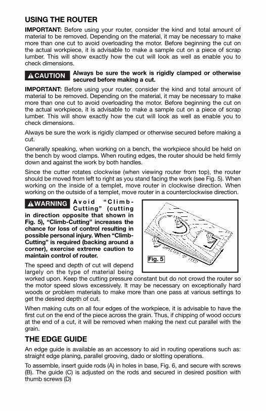
Since the cutter rotates clockwise (when viewing router from top), the router should be moved from left to right as you stand facing the work (see Fig. 5). When working on the inside of a templet, move router in clockwise direction. When working on the outside of a templet, move router in a counterclockwise direction.
A v o i d “ C l i m b -Cutt ing” (cutt ing
in direction opposite that shown in Fig. 5), “Climb-Cutting” increases the chance for loss of control resulting in possible personal injury. When “Climb-Cutting” is required (backing around a corner), exercise extreme caution to maintain control of router.
The speed and depth of cut will depend largely on the type of material being worked upon. Keep the cutting pressure constant but do not crowd the router so the motor speed slows excessively. It may be necessary on exceptionally hard woods or problem materials to make more than one pass at various settings to get the desired depth of cut.
When making cuts on all four edges of the workpiece, it is advisable to have the first cut on the end of the piece across the grain. Thus, if chipping of wood occurs at the end of a cut, it will be removed when making the next cut parallel with the grain.
THE EDGE GUIDEAn edge guide is available as an accessory to aid in routing operations such as: straight edge planing, parallel grooving, dado or slotting operations.
To assemble, insert guide rods (A) in holes in base, Fig. 6, and secure with screws (B). The guide (C) is adjusted on the rods and secured in desired position with thumb screws (D)
Fig. 5

TEMPLET GUIDESA wide variety of templet guides are available for use in pattern and templet routing operations. Fig. 7 shows a typical combination bit, templet guide, and locknut.
Disconnect the tool from the power source.
To install, insert templet guide in center hole in router base and secure in place with the locknut.
NOTE: Before connecting the router to the power source, install, the bit, adjust depth of cut, and rotate the router chuck by hand to be sure the bit or the collet do not contact the templet guide.
B B
D D
A
C
Fig. 6
LOCKNUT
ROUTER BIT
TEMPLET GUIDE
SUB-BASE
BASE
Fig. 7

KEEP TOOL CLEANPeriodically blow out all air passages with dry compressed air. All plastic parts should be cleaned with a soft damp cloth. NEVER use solvents to clean plastic parts. They could possibly dissolve or otherwise damage the material.
Wear ANSI Z87.1 safety glasses while using compressed air.
FAILURE TO STARTShould your tool fail to start, check to make sure the prongs on the cord plug are making good contact in the outlet. Also, check for blown fuses or open circuit breakers in the line.
BRUSH INSPECTION (If applicable)
For your continued safety and electrical protection, brush inspection and replacement on this tool should ONLY be performed by an AUTHORIZED PORTER-CABLE SERVICE STATION or a PORTER-CABLE·DELTA FACTORY SERVICE CENTER.
At approximately 100 hours of use, take or send your tool to your nearest authorized Porter-Cable Service Station to be thoroughly cleaned and inspected. Have worn parts replaced and lubricated with fresh lubricant. Have new brushes installed, and test the tool for performance.
Any loss of power before the above maintenance check may indicate the need for immediate servicing of your tool. DO NOT CONTINUE TO OPERATE TOOL UNDER THIS CONDITION. If proper operating voltage is present, return your tool to the service station for immediate service.
MAINTENANCE


![501585733-CP-T299-3 manual[1] · - 5 - 26. This appliance is provided with double insulation.Use only identical replacement parts. See instructions for servicing double insulated](https://img.pdfslide.net/doc/110x75/6031b0ec8670f239fc0a8463/501585733-cp-t299-3-manual1-5-26-this-appliance-is-provided-with-double-insulationuse.jpg)